

Page 1

...---------------*---------------;;r
HANDBOOK
OPERATION INSTRUCTIONS
1.0.
31R2-4-10l-1
RADIO
MODEl
RECEIVER
SP·600·JX·21
(HAMMARLUND)
LATEST
THE
CHANGED PAGES SUPERSEDE
SAME PAGES OF PREVIOUS
Insert
publication. Destroy
changed
pages
superseded
DATE
into basic
pages.
BASIC AND
_________________
Air
Force
OC,15Jul
65-500-Reprinr
ALL
PUBLISHED
CHANGES HAVE
A
COMPLETE
UNDER
AUTHORITYOFTHE
BEEN
PUBLICATION.
SECRETARYOFTHE
* ---31
MERGED
AIR
CHANGED 1 AUGUST
TO
MAKE THIS
FORCE
15
DECEMBER 1955(
1956-
Page 2

T.O. 31R2-4-101-1
Reproduction
licationisnot permitted
The
and
;;;;--------------
NOTE:
policy
for
Page
No.
the
The
i
21
22
for
non-military
for
use
Navy
portionofthe
useofthe
without
of
Classified Publicationsisestablished
in
Navy
INSERT
text
affected by the
Date
specific
Regulations,
LIST
OF REVISED PAGES ISSUED
LATEST
REVISED PAGES. DESTROY
current
of
Latest
information
approval
Article
revision is
indicated
of
1509.
Revision
1
August
1
August
1
August
1956
1956
1956
or
illustrations contained in this
the
issuing service (BuAer
for
the
Air
Force in
-------------.
SUPERSEDED
by a
vertical
PAGES.
lineinthe
outer
marginsofthe
or
AFR
pub-
USAF).
205-1
page.
*The
asterisk
indicates
USAF·ACTIVITIES.-In
NAVY
ACTIVITIES.-~ubmit
'.
NAS,
Alameda,
NSC,
Guam.
For
listingofavailable
ADDITIONAL
accordance
Callf.;
material
COPIESOFTHIS
with
requestton.earest
NAS,
Jacksonville,
and
A
pages
revised,
PUBLICATION
Technical
detailsofdistribution
supply
Fla.;
Order
NAS,
point
addedordeletedbythe
MAYBEOBTAINEDASFOLLOWS:
No.
00-5-2.
listed
see
Naval
below,
Va.;
Aeronautics
NAS,
Norfolk,
using
San
form.
current
NavAer:140:
DIego,
Callf.;
Publications
revision.
Index
Revised
NASD,
NAS,
Philadelphia,
Seattle,
NavAer
Wash.;
00-500.
1
Pa.;
ASD,
August
USAF
1956
Page 3

T.O. 31R2-4-101-1
Table
of
Contents
Section
I
DESCRIPTION
1-1.
1-3.
1-11.
1-26.
1-31.
1-36.
II
PREPARATION
2-1.
2-3.
2-5.
2-8.
2-12.
TABLE
OF CONTENTS
General
PurposeofEquipment
DescriptionofEquipment
Operational
Capabilities
Equipment
Theory
and
Limitations.
Required
. 4
for
Phone
or
Slow-speed
Telegraph
Reception . 6
FOR
USE
Uncrating
Inspection
ReplacementofDefective
..
Parts
..
SettingUpthe Receiver
Installation
Page
1
1
1
1
5
7
7
7
7
7
10
2-19.
III
OPERATION
3-1.
3-3.
3-22.
3-25.
3-54.
3-57.
IV
EMERGENCY
4-1.
4-3.
4-5.
Testing
General
Description
Presentations
Operating
De-energizing the
of
Controls
and
Readings .
Procedures .
Equipment
PrecautionsToBe Observed
OPERATION
General
Antenna
Emergency
System
Tube
Replacement
..
.................. 22
....
13
14
14
14
16
17
21
21
22
22
22
Revised
1
August
1956
Page 4

Section
T.O. 31R2-4-101-1
Figure
ii
J- 1. Radio Receiver, Model SP-600-JX-2 J
Page 5

T.O. 31R2-4-101-1
SECTION I
DESCRIPTION
1-1.
GENERAL.
1-2.
This
handbook
Radio Receiver, Mod!'.! SP-600-JX-21,
manufactured
Ine.,
New
1-3.
PURPOSE OF EQUIPMENT.
1-4.
The
station, fixed
airborne,
two-way
for
the receptionofkeyed, amplitude-modulated,
frequency-shift carrier signals.
gence may be slow-speed
(automatic)
For
Morse code
cow
and
tion, two-tone
also be used.
1-5.
To
recordable, auxiliary
receiver is to be used
slow-speed
speaker are used;
components
high-speed
lor
a tape ink recorder are required.
shift
teletype reception, use is
shift
converter
writer.
1-6.
The
phone,
denoteadot
(space),
successionofdots
developed
terval
dot
result.
to
ink
in the
the system;orit
unit
inputtoa suitable frequency-shift
with
1-7.
to
monitor.Itmay also be fedtoa transmission linetoprovide the signal
tone
requiring
may be used
phone
may be developedinthe
of
(mark)
The
operate
recorder, a line relay,ora tone
formofa-c
associated
a teletypewriter.
The
provide
used is in
signals.
by the
York1,N.
radio receiver is designed
or
or
field applications,
operational
telegraph,
single-tone carrier signals.
render
telegraph
are usedtomonitor
telegraph
outputofthe receiver,
(mark)
the signal intelligence
in
the
each
and
signalinthe
applicable
tone
the
signal to the headset
a frequency
for
contains
HRmmarlund
Y.
mobile use.Itis
activity.
and
teletype
and
frequency-shift carrier signals may
the signal intelligence audible
components
signals, a headset
in
other
signals, a recorder
equipment
andnodoc
and
formofa-c
dot
(mark),
each dash (space), keyed-tone signals
recording
output
is usedtooperatearecorder
with
the tape
generator
at
the
remote
the
voice frequency range, each signal
bandof170 cycles,
several such tone signals, as well as
operation
adaptable
and
The
radio
The
(manual)
phone,
for
dashes. Alternately,itmay be
teletype, facsimile, ete.
operation,
are required.
the reception
modes
madeofsuitable frequency-
associated
formofdoc
output
being
output
or
for
formofdoc
equipment
provides the audible
ink
recorder,orto
keyed
endofthe line.
instructions
(figure
Manufacturing
for
enclosed-
to shipboard,
may be used
receiver provides
carrier signal intelli-
or
high-speed
use is
made
For
teletype opera-
When
of
phone
and/or
of
operation,
the signal.
for
signals
wherein,
the intervalofeach
generator.
converter
output
and/or
To
driving
with
to denote a dash
containedinthe
output
unit
For
frequency-
a teletype-
other
output
for
is suitable
such as a
The
output
driving
provide
associated
may be used
loudspeaker
The
and
the line
for
1-1)
Co.,
in
and
and/or
the
loud-
these
receive
and
than
the in-
tape
signal
keyed-
for
of
or
to
of
Paragraphs
1-8.
The
radio
receiver provides for continuously vari-
able reception
54.0 mc,
ception
me.
The
its three lower frequency bands
conversion
The
receiver signal-to-noise ratio
teristics
a
signals
of
nonselective
1-9.
oscillator used in heterodyne detection
signals to
set
1-10.
ply designed
phase a-c source
volts.
The
rately fused.
and
tained
apronofthe receiver.
1-11.
1-12.
communications type designed
a
light
top
1-13.
ception
locatedonthe
nector (8, figure
nals are located
of
1-14.
date
input
a 95-ohm transmission line.
stallations specifically designed
frequency may also be used.
the receiver
with
1-15.
provides a received signal (usually frequency-shift)
the
usually as
i-f
b-f-o circuits,
availableatthe
and
short-wave signals which are
The
and/or
The
The
power
the o/g-ampere high-voltage secondary fuse are con-
in
GENERAL.
standard
grey front-panel assemblytowhich are
cover
RECEIVER
of
the
receiver is also locatedonthe
The
a balanced
impedanceofthe
type
The
receiver i-f
output
within
and
for
within
receiver uses single heterodyne conversion
for
provide
the receiver is well suited
and
radio
provide
loudspeaker
radio
to
receiver
transformer
The
cartridge-type fuseholders located
DESCRIPTION OF EQUIPMENT.
19-inch relay rack.Itcomprises a chassis
andabottom
the
headset
re-::eiver
"ANT"
RG-22/U
"IF
partofa space-diversity receiving system.
circuitinthe
the frequency
crystal-controlled fixed-frequency re-
the frequency
its three
for
selective fading.
receiver has an
receiver has a self-contained
operate
within
front
2-1),
on
doubletorstraight-wire
OUTPUT"
output
therefore
"IF
higher
the reception
audio
signal intelligence to the head-
monitor.
from
the
voltage
power
1.6-ampere slow-blow
The
CONNECTOR
panel,
the
input
cable.
OUTPUT"
consumption
primary
radio
plate.
"PHONES"
and
all receiver connectors
rear
apron.
circuit is designedtoaccommo-
receiver is designedtomatch
Other
The
input
connector (8, figure
connector
for
frequency-shift
receiver is isolated
b-f-o injection
rangeof0.54 mc
rangeof0.75 mcto54.0
and
double
bands
and
of
inherently
internal
a 50-cps to 60-cps, single-
rangeof90to270
and
secondary are sepa-
receiver is a 20-tube radio-
for
direct
USES.
jack (20, figure
the
"ANT"
The
rear
suitable
for
the desired
antenna
connector.
Section I
1-1
to
1-15
for
heterodyne
(above
sensitivity charac-
extremely weak
for
of
a-c
(6, figure
7.4
mc).
the reception
subject
beat-frequency
keyed-carrier
power
sup-
is 130 watts.
primary
mounting
With
power
apron.
antenna.
is connected
converter
voltageisnot
on
the
mounted
the
3-1),
input
and
termi-
antenna
operating
from
fuse,
rear
and
ex-
con-
cable
The
in-
2-1)
2-2)
use,
The
the
to
to
to
in
a
at
1
Page 6

Section I
Paragraphs
1-16
T.O. 31R2-4-101-1
to
1-23
1-16.
The
reveiver
figure
2-2)
are suited
transmission line.
"AUDIO
for
a 600-ohm loudspeaker
The
receiver a-c signal
OUTPUT"
terminals (8,
output
(phone,
single-tone telegraphorteletype,ortwo-tone teletype)
is available
render
tone signals intelligible, the tape
high-speed
teletype reception are associated
ment connected
line.
another
at
the
"AUDIO
high-speed telegraph
When
telegraph
a local teletypewriter is used to
and
to
the receiver by suitable transmission
OUTPUT"
and
ink
terminals.
single-tone
recorder used
or
the teletypewriter used
with
demodulator
teletypewriter remotelyorlocally connected to
To
two-
for
for
equip-
operate
the transmission line, the send teletypewriter relay is
connected to the
nals so
that
between the balanced split
of
the receiver, for which the
vides a
mid-point
simultaneous to its
1-17.
The
(2, figure
jumpered
the line
receiver
2-2)
current
tap.
other
"DIODE
and
"AUDIO
output
This
uses.
the
on
"mark"
transformer
jumpered
use
of
OUTPUT"
"AVC"
OUTPUT"
termi-
balances
windings
connection pro-
the line may be
terminals
terminals
out
(3)
are used to interconnect two receivers in a space-
diversity receiving system.
nated
"G"isgrounded
ground
between receivers.
between receivers
while
that
Thisisdonetoprovide
for
amplitude-modulated
this
arrangement,
ceived
the
on
one receiver decreases
noise
output
diversity reception
one
receiver is used.
OUTPUT"
the
"-"
terminal
provides
the
ceptionofcwtoa
the avc duetothe
of
of
terminals
connectedtothe
output.
tone
recorder, the receiver interconnections are as
for
phone,
case
"DIODE
output
with
output
each receiver.
tion
or
the audio
provide
butnoavc
when
the
doc
output
OUTPUT"
is used, the diversity
the
tape
ink
recorder, is
from
the
"AUDIO
To
provide
of
frequency-shift
output
inputtosuitable
The"AVC"
for
each receivertoa
designated
"-"
terminal desig-
is
interconnected
space-diversity reception
or
frequency-shift signal.
stronger
the
weaker signal
the
other.
To
provide
phone,
To
To
the
audio
do this,
are
opened
the
on
jumpered
other
provide
keyer
andnobfo
from
for
space-diversity re-
(generator)
are used.
the three interconnected
terminals is used.
output
one receiver
receiver, which
When
demodulator,
provided
OUTPUT"
for
the space-diversity recep-
carrier
from
each receiver may be used to
frequency-shift
signals,
terminals
the
converter
common
common
signal re-
for
from
"DIODE
or
tape
outlined
This
associated
with
i-f
of
With
and
space-
only
and
is the
the
the
(8)
output
equip-
avc
ink
a-c
a-c
ment.
1-18.
The
"AC"
power
the
rear
apronofthe
an accessory, such as an electric clockorlamp.
available
nected to a
at
power
the
receptacle
source, regardlessofthe settingsofthe
receptacle (12, figure
receiver may be used
whenever
the
2-2)
for
operating
Power
receiver is con-
receiver controls.
1-19.
RECEIVER
tivities require
properly
set
These
controls are all locatedonthe
OPERATION.
that
the receiver switches
for
the
mode
of
operation
All
front
operational
and
ac-
controls be
contemplated.
panelofthe
or
an
of
on
receiver,
control
control
3-1)
control
on
factory adjusted,
adjustment
1-20.
ational
(21, figure
(11)
the a-c sourceisconnectedtothe
applied
When
is disabled
carrier
a two-way communication activity.
in
with
the
on
the
(5,
figure
(7)
used to calibrate
the
front
(4, figure
rear
apron
and
exceptionofthe
2-2)
and
the
panel,
and
2-2),
all threeofwhich are located
of
the
receiver.
are
nottobe
the
the
tuning
"BFO
"METER
"METER
meter
IN]"
These
moved
positions. "
The
radio
activity
turned
through
3-1).
clockwise
receiver is
With
adaptabletoa two-way oper-
useofthe
the
receiver
from
"SEND/REC"
"RF
its
"OFF"
GAIN"
position,
receiver, a-c
for
either
positionofthe
the switch isinits
for
protectioninthe presenceofa
such as
that
produced
"SEND"
"SEND/REC"
position,
by local tranmission
When
its "REC" position, the receiver provides
AD]
RF"
AD]
AF"
(1,
figure
adjustment
controls are
from
their
switch
control
when
power
switch.
the
receiver
strong
local
during
the
switch is
for
instant
is
reception.
1-21.
When
s~lector
tlOn, the
variable
quency
(17).
When
s~t
to
oneofthe
vides
for
any signal
mc,
provided
into
the
selected switch position.
functions
used
to
frequency. Exact
heterodyne oscillator is
control
clockwise, provides
nier
dial
mechanism, to
ceiver
duetovibrationoraccidental
trols.
The
turn
even
1-22.
The
ure
3-1)
or
selectivity.
provides
qualityofthe
of
its
"XT
trol
(23)
is
signal, even
signal.
The
"LIMITER"
ignition
ceiver
audio
1-23.
The
3-1)
in its
"BEAT
justing
the tone
the
radio
switch ;8, figure
"TUNING"
tuning
band
of
any desired
selected by the
the
"FREQ
"XTALS"
receiver
3-1)
control
CONTROL"
"FREQ
is settothe
(15)
provides continuously
carrier
"BAND
within
CHANGE"
selector switch is
positions,
the
CONTROL"
"VFO"
receiver
fixed-frequency crystal-controlled reception
within
numbered
as
adjust
(7).
(6),
the
that
before,
the
frequency
proper
crystal socket
The
and
rangeof0.75 mcto54.0
crystal has been inserted
correspondingtothe
"BAND
the
"TUNING"
the r-f amplifier circuits to
tuning
of
the crystal-controlled first
provided
The
"TUNING
the
main
prevent
optional
LOCK"
locking means
tuning
dial
accidental
CHANGE"
the
by the "6.
(14),
when
for
(4),
and
detuning
control
the
of
shiftofthe con-
"TUNING"
when
the
receiver
provides
The
optimum
received signal.
AL"
positions, the
is used to
control
"TUNING
"SELECTIVITY"
itself remains free
LOCK"islocked.
switch (22, figa choiceofsix degreesofbandwidth
switch
receiver
position
chosen is
performance
When
that
for
the existing
the switch isinone
"XTALPHASING"
highly
attenuate
any
interfering
whenitis closely adjacenttothe
receiver
noise
"LIMITER/OFF"
position
and
other
provides
for
pulse-type noise
switch
effectively
from
(19)inits
output.
receiver
"CW"
OSC."
position
control
output
"MOD/CW"
renders
(10)
provides the meansofad-
within
a frequency
switch (13, figure
the
bfo
operative.
rangeof±3
posi-
the
fre-
switch
pro-
switch
operating
FREQ"
turned
the ver-
tuning
the
re-
which
con-
desired
reducing
the
re-
The
of
is
to
2
Page 7

w
3.5MC
CRYSTAL
OSCILLATOR
~
l--.-I
R-F
AMPLIFIERS
l....c
r--1
"XTALS"
MIXER
A
"FREQ CONTROL"
"VFO"
~+-C;1f
O)~
'/
,,?J
r
v
MIXER
i'~s
. .
S~.
uf-o"
V'G'
GATE •
'.~...
'f-('
",
'.le,
t>-~
CRYSTAL
FILTER
~
1-
F H DETECTOR
AMPLIFIERS AVC
-----
, , • , , , SIGNAL
SIGNAL
~
L....j FREQUENCY
BEAT
OSCILLATOR
PATH
FOR
PATH
FOR
LOUDSPEAKER
1-+
AMPLlF~
POWER
SUPPLY
A-C -
SOURCE
FREQUENCIES ABOVE
FREQUENCIES BELOW
!4-
7.4MC
7.4
MC
-l
?
Co)
;:lll
-
~
.
,Ill.
I
-
o
-
•
-
CRYSTAL
CONTROLLED
OSCILLATOR
w
VARIABLE
FREQUENCY
OSCILLATOR
figure
i
-2.
Radio Receiver,
Simplified
Block Diagram
VI
(1)
n
-
o'
~
Page 8

Section I
Paragraphs
1-24
to
T.O. 31R2-4-101-1
1-29
kc.
The
"BEAT
directiononscale to
ceived
cow
the
"MOD"
tionofamplitude-modulated
is to be used
nal,
the
"MOD/CW"
whether
the receiver i-f
OSc."
signal.
provide
When
control
the
may be
the 3-kc
range
"MOD/CW"
turnedineither
position, the receiver provides
signals.
for
the receptionofa frequency-shift sig-
switch
positionisdependent
When
outputorthe receiver a-f
for
switch is
for
the recep-
the
the re-
receiver
upon
output
istobe furnishedtothe associated frequency-shift converter
equipment.
the use
of
the
monitoring
used,
the
bfo
istoprovide
band)
reception, the
at
the receiver.
controlisset
When
bfo
purposes.
the receiver i-f
provides
When
mustbein
suppressed-carrier
bfo
For
this application, the
to a
position
output
optional
receiver
output
the receiver a-f
operation.
When
the receiver
(singleordouble
is usedtoreinsert the
"BEAT
providing
a bfo frequency
is used,
for
output
side-
carrier
OSc."
455 ke.
1-24.
The
receiver
3-1)
is adjustable to compensate
encountered in the level
maintain the receiver a-f
limits
for
the
receiver incorporates automatic volume control.
ceiver
"A
cluded
"AYC/MAN"
YC"
position, provides this action. Provisions are in-
in
the receiver
the reception
"RF
GAIN"
control
the"AYC/MAN"
1-25.
The
receiver
vides a
tuning
the"AYC/MAN"
position.
to
When
its maximum clockwise setting, the meter
"RF
"RF
GAIN"
of
slow-speed
switch.
tuning
indication
switch
the
"RF
GAIN"
of
output
control
control
for
wide
(11, figure
variations
any carrier received.
constant
setting
within
chosen, the
narrow
The
switch
for
a-v-c
(12),
operation
telegraph
when
set to the
even
during
signals.
is effective in either position
meter (1, figure
for
the desired signal,
(12)
is
set to the"AYC"
GAIN"
control
3-1)
(11)
when
is set
top
To
re-
The
pro-
scale
indication is the ratioofthe received signal level to a
signal
of
one microvolt, expressed
"METER"
switch
position, the meter
of
the receiver audio
(18)isheldinits depressed
bottom
scale indication is the ratio
outputtothe
in
db.
standard
When
reference
the
"AF"
outputofsix milliwatts, expressedindb.
1-26.
1-27.
radio
path
OPERATiONAL THEORY.
GENERAL.
An
analysisofthe
operationofthe
receiver is best evolved by considering the signal
through
the receiver r-f, i-f,
and
a-f sections,
into
which the receiver may be considered theoretically subdivided.
is considered separately.
(figure
between the various sections
1-28.
vides selective circuitry
receiver frequency
through
housed in a rotary
one
tenna
oscillator r-f tuner.
figure
The
1-2)
R-F
SECTION.
self-contained
indicatesinblock
power
supplyofthe receiver
The
simplified block
form
of
the receiver.
The
r-f
sectionofthe receiver pro-
for
any selected signal
the relationship
rangeof0.54to54.0 me.Itdoes this
the useofsix setsofr-f
turret
frequency
bandofthe receiver
assembly. Each set is used
tuner
subassemblies
and
comprises an an-
r-f tuner, two identical interstage r-f tuners,
The
3-1)
provides
"BAND
for
CHANGE"
indenting
the rotary
diagram
within
switch
turret
and
the
for
an
(17,
as-
of
of
in
sembly so
frequency
ceiver.
the signal assures
developed in the r-f section· is
very weak signals
r-f
the signal is greatlyinexcessofthat
that
the
r-f
tuner
subassemblies
band
The
become
antenna
partofthe
and
two-stage r-f
that
the signal-plus-noise to noise
provide
useful receiver
section preselection assures
r-f
high
enoughsothat
that
the
sectionofthe regain
gain
provided
desired signal. Since the receiver utilizes the principles
superheterodyne reception, a signal removed
sired signal by twice the 455-kc
is
also provides
the receiver.
sired signal, is
tunedinon
an
i-f signal acceptable to the i-f section
This
image frequency, like any
greatly
the three
ceiver, the image frequency
quency
signal.
ceiver provides
these bands.
7.4
i-f signal.
first
of
455 kc
To
maintain
On
me),
the signal
On
heterodyned
would
for
double
the three lower frequency
tunedinis
the three
to a 3955-kc i-f signal, which is
heterodynedtoa 455-kc i-f signal.
"FREQ
CONTROL"
position, the receiver provides
tuning.
When
the switch isinoneofits
tions, the receiver first
attenuated. However,
higher
high
image-rejection ratios, the re-
higher
selector switch
heterodyne
intermediate
frequency
for
bandsofthe re-
an intermediate fre-
be too close
superheterodyne reception
heterodyned
frequency bands,itis
With
(8)inits
for
continuously variable
variable oscillator is
replaced by a fixed-frequency crystal-controlled heterodyne oscillator.
stability
frequency
tion
channel, even
without
necessitating a time-consuming search by the
superior
tuning.
Doing
this resultsinreceiver frequency
to
that
attainable
Its use pre-establishes the communica-
when
receiving conditions are poor,
operator.
1-29.
I-F
SECTION.
corporates the 455-kc i-f amplifier
all
of
the overall
developed. Also,
The
i-f sectionofthe receiver in-
wherein
gain
and
selectivityofthe receiver is
it
incorporates the single-double conversion switch, which assumes its single
version position
is
indented
three
higher
dependentonwhether
respectively
for
frequency bands.
the
oneofits three
For
signals
oneofthe three lower frequency bands, the signal has
access
to
the 455-kc i-f amplifier
gate.
For
this
condition
the switch
conversion i-f channel inoperative.
on
oneofthe three
higher
reaches the 455-kc i-f amplifier
double-conversion channel.
renders the 455-kc i-f
of
receiver selectivity
switch (22, figure
channel
of
3-1)
the receiver.
For
gate
provided
are developedinthe 455-kc i-f
At
through
renders
For
signals
frequency bands,
through
this cOJ;ldition the switch
inoperative.
by the
the
"SELECTIYITY"
input
to the 455-kc i-f
amplifier is the 455-kc i-f crystal-filter circuit incorporated
in
the receiver.
the receiver to
selectivity.
The
mechanism provides
and
calibration accuracyofthe receiver so
The
useofthe crystal filter enables
attain
the
three degreesofsharp
precise antibacklash
for
completely accurate resetability
gear-train
foraparticular
provided
ratio
even
output.
The
available
any un-
from
the de-
frequency
other
unde-
for
signals
to
the desired
bands
(below
to a 455-kc
then
the receiver
"YFO"
"XT
ALS" posi-
for
variable-
practically
or
double
rotary
con-
turret
lower
tunedinon
a 455-kc i-f
the double-
tuned
the
signal
the 3955-kc i-f
The
six choices
"XTAL"
tuning
that
maximum
to
to
of
of
on
or
in
4
Page 9

benefit can be derived
of
the 455-kc i-f crystal filter.
control
bfo
"IF
ated
1-30.
sectionofthe
develop
"AUDIO
control
terminals
(23)ispartofthe crystal filter.
and
associated
OUTPUT"
with
the 455-kc i-f channelofthe
A-F
SECTION
receiver incorporatesana-f amplifier to
the
a-f
GAIN"
the receiver
(8,
figure
jack (20, figure
develops all
rhe receiver.
lated to
stability.
the
The
maintain
The
"RF
from
the
sharp,
The
"BEAT
OSc."
connector (6, figure
AND
POWER
power
control
output
(16, figure
of
outputtothe
2-2)
and
thattothe
3-1).
The
self-contained
a-c
and
the
doc
supply
critical
constant
GAIN"
doc
supply
the sensitivity
control
crystal passbands
"XTALPHASING"
The
455
control
(10)
2-2)
receiver.
SUPPLY.
the receiver.
3-1)
"AUDIO
OUTPUT"
"PHONES"
power
voltages used by
voltages are regu-
and
(11)ispartofthe
power-supply bias rectifier. Its chosen setting,
junction
used, determines the
sections
1-31.
1-32.
receiver
ated.
tiontoa balanced
tem.
relative locationsofthe receiver
In
within
relative humiditiesashigh
minute
from
quency.
shielding
mum.
in
board
chassis rigidity
It
ditionitfor
1-33.
signal
tent
volt,
have tobeat
velop
quencies
would havetobe
to 600 kc, a 455-kc signal
to
microvolt
600 kc, this 455-kc i-f rejection
better. Likewise,
receiver is 'it least 50,000
bands4,5,or6,
kc
1-34.
(minimum
with
the
a-v-c system
gain
developedinthe
of
the receiver.
CAPABILITIES
GENERAL.
performance
The
antenna
The
95-ohm cable used provides flexibility astothe
AND
The
when
input
doublet
LIMITATIONS.
radio
receiver provides
properly
connector
or
single-wire
and
use,
the
receiver may
the
rangeofO°C
be
subjected to temperatures
(32°F)
as 95 percent.
warmup
0.001
The
to reduce
This
multi-receiver installations
regulations.
is adequately treated
period,
percentto0.01
the
frequency stability ranges
percent
receiver incorporates advanced design
radiation
characteristics to a mini-
enables the receiver to
and
The
receiver embodies the necessary
to
withstand
with
severe
fungicidal
tropical use.
PRESELECTION.
tunedinon
thatifthe desired signal
the
strengthofthe image frequency signal
the
The
image frequency
receiver is
strength
least 4000 microvolts
the
same receiver
the
strength
of
output.
the
image frequency
greater. Also,ifthe receiveristuned
inputtothe receiver
be
2700 microvoltstoproduce
signalat600 kc.
the
the
frequency
i-f
channelofthe receiver is operative.
-SENSITIVITY.
signal
input
For
3955-kc i-f rejection ratioofthe
for
any
bands
The
receiver
to develop its
of
the receiver,
r-f
installed
provides
for
antenna
the
antenna
to
60°C
(140°F),
Aftera15-
of
the
signal
maintain
performance
to comply
vibration
and
varnishtocon-
attenuatedtothe
were
one
(at
7.4 mc)tode-
At
other
signal fre-
the same effect as a one-
frequencies
other
ratioofthe
signal
for
frequency
which
threshold
rated
a-f
T.O. 31R2-4-101-1
-+-
3-kc
and
the
are
associ-
The
a-f
The
is used to
supply
frequency
in
con-
when
and
i-f
optimum
and
oper-
connec-
sys-
system.
at
fre-
and
with
ship-
shock.
of
any
ex-
micro-
would
signal
will
have
than
receiver is
on
the
3955-
sensitivity
output)
is
Paragraphs
two
microvolts
a
cow
signal,orbetter.
the
receiveratthreshold
This
a-f
noise
power
optimum
signal
tuned
the first electron
not
interfere
be
reduced in
the
"RF
wise
from
to
prevenr
receiver.
turning
wise.
the
Thisisdone
sectionofthe
receptionatthe
for
an
A-M
The
sensitivity is
outputisprovided
ratio
of
ten
receiver
GAIN"
its
performanceinthe
in, since
with
the
the
tube
and
reception.
presenceofa
control
maximum
clockwise position.
(11, figure
overloadingofthe
The
receiver a-f
"AUDIO
to
receiver
GAIN"
prevent
andtoprovide
desired a-f
signal,
undistorted
at
to
background
the
The
r-f
output
control
output
ceiver a-v-c system is operative
control
ceiver
age
microvolts.
put
strong
control,
acteristics
is set to its
output
ratio
remains
when
The
when
tuning
comparedtothe
and
compensates
of
the
the
maximum
constant
input
clockwise setting, the re-
withinaone-to-four
is increased
useofave precludes excessive audio
through
a carrier signal relatively
settingofthe
for
the
signal
over
longorshort
time.
1-35.
SELECTIVITY.
of
the
receiver is adjustable to
of
a signal
under
Since noise, regardlessofits
and
comprises
audio
outputofthe
selectivity
of
the
all
receiver.
"SELECTIVITY"
noise
output
of
noise,itis advantageous to restrict
ceiver
with
intelligible
quirements
For
phone
than
bandwidth
vary
reception,
reception. However, the
with
ments are 455 kc
ment
for
single-tone
operation
words
per
kc
±
two
two
doubled.
the
such as slow-speed telegraph, teletype
per
minute),
minute),
75
tones,
cps,
one
the
and
for
requirements
channels are used,
The
bandwidth
frequency stability
frequency stabilityofthe
ofacow
provide
signal, a
for
receptionofphone
The
bandwidth,
provide
varying
conditionsofpropagation.
origin,isof
frequencies,
receiver
The
depends
"BROAD"
switch (22, figure
the
"SHARP"
to
the
narrowest
the typeofsignal
the
i-f
channel
± 2500 cps.
telegraph
and
high-speed telegraph
are
455 kc
"mark"
the
of
narrow
-+-
600 cps, respectively.
and
bandwidth
requirements
the
receiver itself.
bandwidth
may be reduced to reduce noise
use
ofanarrower
higher-frequency
nal
and
may
impair
provide
for
receptionoftelegraph
bandwidth
audio
componentsinthe received sig-
the
intelligibilityofreception. To
Section I
1-30
to
and
0.75
microvolt
power
two
output
wattsorbetter.
a signal-plus-noise
one.
This
provides
presenceofa
noise caused by
antenna
r-f
tuner
receiver sensitivity may
strong
signal by
3-1)
turning
counterclock-
Thisisdone
and
i-f sectionsofthe
may be decreased by
(16)
counterclock-
overloading
level.
and
the
from2to
"AUDIO
possible
of
for
comfortable
When
"RF
fading
the
the
GAIN"
200,000
GAIN"
intervals
or
selectivity,
for
the
reception
the
pulse type
the
noise level
upon
the
in
overall
settingsofthe
3-1)
produce
settings.Inthe
the
presence
overall
possible, consistent
bandwidth
being
received.
bandpass
This
is also
reception.
455 kc
the
For
keyed c-w
(400
-1-
50 cps, 455
requirerequire-
words
When
another
for
"space",
requirements
also
depend
received
signal
For
and
reception
can be used.
signals,
output;
results
the
bandwidth
however,
in
loss
or
teletype signals,
of
1-35
for
of
to
for
weak
does
a-f
re-
volt-
out·
char-
of
the
more
re-
re-
(60
or
are
upon
the
To
the
the
5
Page 10

Section I
Paragraphs
1-36
to
T.O. 31R2-4-101-1
1-37
full
advantage
should
be takenofthe
switch positions to reduce
LECTIVITY"
overall
switch provides a choiceofsix degrees
bandwidth.
The
widths are 0.2 kc, 0.5 kc,
crystal
1-36.
1-37.
quired
signals is subdivided
supplied
tableI.The
bandwidths
EQUIPMENT REQUIRED FOR PHONE OR
SLOW-SPEED TELEGRAPH RECEPTION.
The
tabulation
are 3.0 kc, 8.0 kc,
of
for receptionofphoneorslow-speed telegraph
into
and
covered by this publicationislisted
components
receiving system, required
in
table II.
TABLEI.EQUIPMENT SUPPLIED
Quantity
1
Radio
Receiver,
SP-600-JX-21
antenna
1
1
1
Plug,
Adapter,
Plug, i-f
angle
output
"SELECTIVITY"
interfering
noise.
The
sharp, crystal-derived bandand
1.3 kc.
the complete
two tables.
and
auxiliary
but
not
Name
The
broad, non-
and
13.0 kc.
equipment
The
equipment
equipmentofthe
supplied, are listed
Government
Designation
Model
connector
plug
connector
UG-102/U
UG-104/U
PL-259
"SE-
of
re-
in
TABLE
EQUIPMENT REQUIRED BUT
Quantity
*AR
II.
COMPONENTS
Name
Crystal, Specification
MIL-C-3098
1
1
1
AR
1
Headset
Cord, headset
Loudspeaker
Cable, lead-in
Antenna
anced
system, bal-
doublet
single wire
1
Source, a-c, single-
phase, 90 to 270V,
50to60
cps,
watts
*One
crystal
required
for
quency.
each
AND
AUXILIARY
NOT
or
130
operational
SUPPLIED
Government
Designation
CR-18/U
Navy
Type
-49507
Navy
Type
-49534
LS-3
RG-22/U
signal fre-
6
Page 11

T.O. 31R2-4-101-1
Paragraphs
2-1
Section
to
II
2-9
2-1.
UNCRATING.
2-2.
Carefully remove
container, using the
a.
Remove the two steel straps
b.
Remove the cover nailedtothe case.
c.
Remove the excelsior
"the
following
from
receiver
ceIver.
d. Remove the
e.
Remove the
waterproof
and
remove the
f.
Open
taining
the receiver.
g. Remove
paper
the
the
carton
cartoned
waterproof
wrapped
waterproof
vapor-proof
around
and
remove the
receiver
paper
carton.
Un
flatten the cornersofthe
h.
and
remove the silica gel.
wood
i. Remove the
corrugated
front, one back,
interiors
and
j. Remove the receiver
convenient
k.
Put
place
all
packing
frame
comprising
one top, each accordion folded.
and
near
its final location.
materialinthe
store.
2-3.
INSPECTION.
2-4.
When
shipping
damage
front
panel controls, the
meter
that
they are firmly seated
none
are
the
rear
of
the
the
receiver has
container, carefully inspectitfor
that
may have occurredinshipment.
tuning
for
any defects. Inspect the tubestomake
broken. Inspect the fusesinthe fuseholders
apronofthe
proper
ratings
receiver to make certain
are
insertedinthe
SECTION
PREPARATION FOR
from
its
shipping
procedure:
from
the
wooden
around
tape
the
from
from
the foldsofthe
the
cartoned
cartoned
the
wrapper.
inner
bag
from
around
inner
carton,
from
the
carton,
two
side pieces,
setitoutofthe wayina
wooden
been
removed
any signs
dial windows,
in
their
sockets
fuseholders.
case.
receiver,
carton
the
open
and
case
from
Inspect
and
and
that
case.
con-
inner
sure
fuses
re-
it,
the
one
and
its
of
the
the
that
on
II
USE
To
remove
b.
screw
holding
counterclockwise,
remove
the
is removed
c.
To
remove any electron tube
or
V19, first remove
clockwise
cept
removed
2-7.
the
while
V17
and
withanappropriate
FUSES.
o/s-ampere fuse, located respectivelyinthe
fuseholder
( 1)onthe
of
the
fuseholder
grees
in
a counterclockwise direction.
pressureinthis
spring-clamped
and
the
topofthe
To
replace
Be certaintouse fuses
fied above. Use
in
damagetothe
2-8.
SETTING UP
2-9.
POWER
When
shipped, the
the receiver is connectedtooperate
117-volt, a-c source.
from
other
tap. connection.
ratIngofeachofthe
electron
the
tube
while
tube shield.
preferably
tube
V4, loosen
shield.
with
Then
turn
exerting
The
inward
tube isofthe
a suitable tube remover.
other
the
tube shield by
exerting
V19
inward
areofthe
pin
pressure.
type,
tube remover.
To
remove
(11, figure
rear
apronofthe receiver, pressinthe
while
position
to
the
fuseholder
either
fuse,
either
the
2-2)
and
the
turningitapproximately
will
release the fuse
topofthe fuseholder.
may
nowbepulled
follow
of
any
the
having
other
reverse
the
fuses may
receiver.
THE
RECEIVER.
TRANSFORMER
power
transformer
from
If
the
receiver is
than
a 117-volt source, change the
Table
III shows
primary
the
tap
terminals,
the
knurled
the
tube
shield
pressure,
pin
type
than
V4
V17
twisting
and
c~unter~
All
tubes ex-
are
preferably
1.6-ampere fuse
"LINE"
"-B"
fuseholder
45 de-
Removing
which
The
apart.
procedure.
ratings
speciresult
CONNECTIONS.
primary
tap
a 50-to60-cps,
to
be
operated
primary
a-c source
voltage
which
and
and
or
top
the
is
fuse
of
are
2-5.
REPLACEMENT OF
2-6.
ELECTRON
discovered
before
tron
operation
tubes use the
during
TUBES.Ifdefective electron tubes are
inspection, replacement
is attempted.
DEFECTIVE
following
To
replace defective elec-
procedure. (See figure
2-1.)
a.
To
remove electron tubes
hat-type tube clamp
the clamp, press
inwardonthe
must
V17
and
first be removed.
spring,
clamp off the tube. Remove the tube by
from
its
tube
ingiton
the
ad jacenttoit
spring,
the
with
clamp
is firmly seatedinplace.
socket. Replace the
topofthe
tube so
canbethreaded
pressure
providingaratchet
top-hat
that
through
PARTS.
mustbemade
V19,
the
To
remove
while
lifting
drawingitout
clamp
by seat-
the
vertical
the
holeinthe
motion
top-
the
bolt
until
TABLE
Tap
III.
POWER TRANSFORMER
TAP VOLTAGE RATINGS
No.
2
3
4
5
6
7
8
9
Voltage
105
117
130
190
210
234
260
Rating
95
7
Page 12

Section II
T.O.
31R~-4·101-1
27---
26
25
24
23
------or
3
4
5
7
8
10
II
....
15
19
tube
tube
thumbscrew
spring
sockets
tube
tube
lamp
buttons
V3
V2
assembly
V5
V13
View
18
of
17
Chassis
19.
20.
21.
22.
23.
24.
25.
26.
27.
16
Electron
Electron
Electron
Electron
Electron
Electron
Electron
Electron
Electron
tube
tube
tube
tube
tube
tube
tube
tube
tube
V4
V8
V7
V6
V9
VIO
V18
V14
Vll
1.
2.
3.
4.
5.
Electron
6.
7.
"GND"
8.
"ANT"
9.
Electron
Electron
Electron
Electron
Electron
Electron
tubeV12
tube
tubeV15
tube
tube
tube
terminal
input
tube
22
V16
V17
V19
V20
connector
V1
Figure
21
2-1.
20
10.
Electron
11.
Electron
12.
Knurled
13.
Retainer
14.
Crystal
15.
Electron
16.
Electron
17.
Pilot
18.
Metal
Radio Receiver, Top
8
Page 13

T.O. 31R2-4-101-1
Paragraphs
2-10
Section
to
2-11
II
identified by numerical designation
the
power
transformer
Choose the power
whose voltage
rating
(13, figure
2-2).
transformer
is closest to the available
a-c source voltage.
2-10.
When
obtained
ure
and
adding
CRYSTAL SELECTION
fixed-frequency, crystal-controlled
be utilized, the
2-1).
and
When
proper
inserted
ordering
type
into
the signal frequency
1, 2,
and3,the
455 kctothe
the signal-frequency
crystal frequency
signal frequency;
rangeof7.4 mc to 12.045 mc,
AND
CR-18/U
the crystal
a crystal, the crystal frequency
should
be specified.
can
crystal frequency can be calculated by
on
the
bottom
primary
tap
MOUNTING.
operationisto
crystal(s)'
socket(s)
must
(14, fig-
For
bands
be calculated by
for
band4,in
adding
3955
of
be
the
kc
to the signal frequency;
12.045 mc,
can be calculated by
quency
2-11.
proceed
a.
frequency-control unit,
sembly
b.
on
and
dividing
To
mount
as
follows:
Loosen the
(13)tothe
Insert
the
bands 4,5,and
adding
the sum by three.
the crystal unitsinthe
knurled
thumbscrew
and
rear.
crystals
into
numbered1through6,on
e.
Bripg
the
retainer
the springs are over
sockets,
(9, figure
crystals are
and
tighten
d.
Usingapenorpencil,
3-1)
intended.
spring
the
the
the signal frequencies
for
signal frequencies above
6, the crystal frequency
3955 kctothe signal fre-
crystal sockets,
(12)ontopofthe
push
the
retainer
the crystal sockets
the frequency-control
tops
knurled
mark
assembly
of
thumbscrew.
forward
the crystals
on
the plastic
for
spring
in
which
as-
(14),
unit.
until
the
chart
the
13
12
L
"-B"
2.
"DIODE
3."AVC"
4.
"BFO
5.
"METER
6.
"IF
OUTPUT"
II
fuse
OUTPUT"
terminals
IN}"
AD]
control
RF"
connector
10
terminals
control
13.
9
Power
8
transformer
7
~'-
7.
"METER
8.
"AUDIO
9.
Power
10. "SPARE FUSES"
1L
"LINE"
12.
"AC"
AD]
OUTPUT"
cord
fuse
power
receptacle
AF"
6
control
cover
~
e
'"
terminals
2
3
4
5
Figure
2-2.
Radio Receiver, Rear
View
9
Page 14

Section
Paragraphs
II
2-12
T.O. 31R2-4-101-1
to
2-18
2-12.
2-13.
mountingina
panel is 10
tion which permits the free access
2-14.
at the
the tap which
cps
the receiver
power
2-15.
The
accommodate a balanced
installation;
specifically designed
may be used.
INSTALLATION.
MOUNTING.
1
/
2
POWER.
bottomofthe
power
source voltage;
into
plug.
ANTENNA
antenna
input
however,
The
receiver is designed
standard
inches high.
Make
most
19-inch rack.
Mount
sure
that
power
transformer
nearly agrees
The
the receiver in a posi-
of
air.
the
primary-tap
with
the 50-cpsto60-
refertoparagraph
the
power
AND
source
GROUND
using
CONNECTIONS.
circuitofthe receiver is designed
doubletorsingle-wire
other
The
for
input
suitable
the
desired
impedance
antenna
operating
of
for
rack
receiver
front
lead
is connected
2-9.
Plug
the receiver
antenna
systems
frequency
the receiver is
designed to match a 95-ohm transmission line. Connect the
ure
angle
plug. Figure
tion procedure.
to be used, connect the
terminal
the
"GND"
ceiver
ing
antenna
2-1)
plug
of
other
terminalofthe connector
terminal
"GND"
a suitable
to the
using type
adapter,
2-3
If
the
connector
(7).Inall installations,
terminal
bonding
illustrates the antenna-cable fabrica-
a single-wire
"ANT"
RG-22/U
and
input
connector (8, fig-
cable, a type
a type UG-102/TJ connector
antenna
plug
andaground
antenna
installation
lead-in wire to one
plug
to the receiver
bond
to the
installation
strap.
UG-104/U
lead
from
the re-
ground,
us-
to
to
is
2-16.
headset
Either
HEADSET.
into
the
"PHONES"
For
monitoring
jack (20, figure
a high-impedanceora low-impedance headset may
be used; however, the high-impedance
is recommended.
2-17.
dynamic-type,
matching
terminals (8, figure
the
move
of
minals,
LOUDSPEAKER.
loudspeaker
'transformer
insertionofd-c
the
jumper
the 600-ohm
and
connect the
When
the 600-ohm
Connectapermanent-magnet,
w~.th
across the
2-2).
For
controlorindicating
connecting the
outputatthe
"AUDIO
insertion
outputisnot
a suitable 600-ohm
"AUDIO
applications
two
circuitinits place.
a 600-ohm, 2-watt resistor across the
OUTPUT"
age
from
2-18.
RECEIVER
DIVER~ITY
a.
Receiver interconnections
tionofphone
the"AVC"
on
each receiver to a
the"AVC"
ceivers.
minals
Open
(2)
terminals to avoid
high
transient
peak voltages.
INTERCONNECTIONS
RECEPTION.
signals are
showninfigure
terminals (3, figure
common
terminals designated
the
on
jumpered
one
of
"DIODE
the receivers,
component
for
space-diversity recep-
2-2)
ground
"-"
purposes,
plug
3-1).
(8000-ohm)
type
OUTPUT"
requiring
voltages, re-
balanced sections
OUTPUT"
used, connect
"AUDIO
dam-
FOR
2-4.
Connect
designated
and
interconnec.t
on
the
"G"
two
OUTPUT"
and
connect the
a
ter-
re-
ter-
10
COUPLING
Figure
RING
2-3.
BACK SHELL
Cut end of cable even. Remove vinyl
Bare
5/8
in. of
Slide coupling
der
hole should align with
Assemble
and
solder
cessive
For
back
final
front
shells
holes.
heat.
assembly;
Fabrication
FRONT
conductors.
ringoncable.
shell
should align.
Solder
screw
of
Antenna
SHELL
Tin
conductorsasshown.
to back
shell.
conductorstocontacts.
coupling
Cable
exposed
Screw
Solder
jacket
conductors
back
shelloncable.
Solder
holes
braidtoshells
ring
on back
1-1/8
in.
in both
Do not
shell.
and
use
braid.
Sol-
front
through
ex-
Page 15

T.O. 31R2-4-101-1
JUMPER REMOVED
/"
Section
II
Figure
SP-600-JX-21
SP-600-JX-21
2-4.
Receiver
DIODE/OUTP~T
-
0
DIODE OUTPUT
-
Interconnections for
+
AUDIO OUTPUT
o.------1:l
v
+
AUDIO OUTPUT
a.---------o
Phone
AVC
1-
AVC
-
Space-diversity
G
0
~
G
TO
LOUDSPEA
Receiving
KER
System
SP-600-JX-21
SP-600-JX
-21
jV
DIODE/OUT:UT
-
AUDIO OUTPUT
0
OUTPUT
DIODE
---r.
-
+
AUDIO
I
I
-l-
JUMPER REMOVED
AVe
0 0
+
-
a...-----u
Ave
0 0
-
OUTPUT
a..-----o
AA/\
600
OHMS
2WATIS
TAPE
RECORDER
G
0
G
I
I
INK
Figure
2-5.
Receiver
Interconnections
for
Space-diversity
D-C
Output
Receiving
System
11
Page 16

Section
11
T.O. 31R2-4-101-1
1-
"""'"0
AVC
G
:~
I
I
I
I
I
I
SP-600-JX-21
r----------------~
DIODE OUTPUT
a---u
-
1·.
I • • I
I
I
,
+
AUDIO OUTPUT
0-
••
••••.t\I\I'v- • •••: I
600
OHMS
2
WATTS
I
I
I
r------------------------~
I
I
I
I
I
I
I
I
I
I
I
I
I
I
I
I
I
I
I
I
I
I
I
-------------
L--
______________
SP-600-JX-21
r------
I
I
I
I
I
I
I
I
I
I
I
L
r--------------~
I
I
I
I
I
I
I
I
L
_____
___
DIODE OUTPUT
0-
.."
-
~.
I •
I
I
I
+
AUDIO OUTPUT
0.------0
eo
••••
600
I
I
I
J
~
~
-0
-0
RADIO TELETYPE
TERMINAL
EQUIPMENT
"/\/\/\,,.
2
WATTS
OHMS
AVC
-
•••
•
• I
0-
G
.~
I
I
I
I
I
I
I
I
IF
OUTPUT
[~}
~
IF
OUTPUT
[~]
----
........
INDICATES CONNECTIONS
A-F
SIGNAL OUTPUT
INDICATES CONNECTIONS
I-F SIGNAL OUTPUT
INDICATES CONNECTIONS COMMON
TO
BOTH SYSTEMS
.....
•
••
••
FREQUENCY - SHIFT
CONVERTER
10·
•
FOR
FOR
Figure
"DIODE
like
speaker across the
of
the second receiver.
b.
connect the
the
12
OUTPUT"
terminalofthe second receiver. Connect the loud-
For
space-diversity receptionofcow
jumpered
2-6.
Receiver
terminals designated
"AUDIO
two
receiversasshowninfigure
"DIODE
OUTPUT"
OUTPUT"
Interconnections
terminals
signals,
terminalsofone
for Frequency-shift
"-"
to
the
(8)
inter-
2-5.
Open
of
the receivers,
minal
designated
receiver.
OUTPUT"
ment.
c.
reception
in
figure
Connect
The
interconnections required
of
2-6.
Space-diversity
and
connect the
"-"tothe like
the three interconnected
terminalstothe associated
frequency-shift carrier signals are
Interconnect
Receiving
"DIODE
the
"AVC"
System
OUTPUT"
terminalofthe second
recording
for
terminalsofthe
ter-
"DIODE
equip-
space-diversity
shown
Page 17

T.O. 31R2-4-101-1
Paragraphs
2-19
Section
to
2-20
II
,--
. .
two
receivers as
the
jumpers
the receivers.
equipment
receiver
ated
to the
ifanaudio
terminal
used, connect
2-2)
of
each receiver to the associated frequency-shift
converter
plugs.
output
equipment,
For
cable,
COUPLING RING
- -
--
.,.
per
step
across the
"DIODE
Connect
"AUDIO
signal is to be
equipment,orif
the
"IF
OUTPUT"
using
.-,
figure
"a"ofthis
OUTPUT"
2-7.
paragraph.
terminals
fabrication
the frequency-shift converter
OUTPUT"
terminalsofeach
applied
to the associ-
a 45S-kc signal istobe
connector (6, figure
RG-ll/U
cable
and
PL-259
fabrication instructions applicabletothe
refer
to figure
2-7.
Keep
of
i-f
PLUG
Cut
endofcable
Bare
5/8
coupling
braid.
Screw
braid
of
For
in. of
ringoncable.
the
through
braidtoshell.
final
assembly,
of
2-19.
2-20.
the complete
receiver
ure
tion
position.
Then
possible
following
graph
SUB-ASSEMBLY
even.
Remove
center
conductor.
Tin
plug
sub-assembly
solder
holes.
Solder
center
screw
I-f
Output
TESTING.
When
3-1)
and
check the
3-25
Cable
the
installation
onbyrotating
in
a clockwise direction
set
the
"SEND/REC"
Allow
the receivertowarmupfor
operationofthe
modesofoperation
the
operating
as applicable.
vinyl
Trim
exposed
on
cable.
Use
enough
conductortocontact.
coupling
ringonplug
equipment
for
the
"RF
procedures
jacket
1-1/8
in.
braided
center
shield.
conductor
Solder
assembly
heattocreate
sub-assembly.
Slide
and
to
bond
has been installed, check
proper
operation.
GAIN"
from
switch
(21)toits "REC"
control
its
"OFF"
Turn
(11, fig-
15 minutes.
receiverinthe various
on
eachofthe
outlined
six bands,
under
the
posi-
para-
13
Page 18

Section
Paragraphs
III
3-1
to
T.O. 31R2-4-101-1
3-13
SECTION
OPERATION
3-1.
GENERAL.
3-2.
For
optimum
ing
procedures
operating
of
signal to be received,
communications
The
ation
3-3.
3-4.
are all located
figure
the
3-5.
cuits by
wise
integral
its
actuation
illuminationofthe
dial
3-6.
ables the r-f section
"SEND"
mission intervals
prevent
local transmission.
"REC"
3-7.
switch
includes the desired signal frequency.
is
indicatedatthe
the
matically positioned
frequency
3-8.
the
amplifier section
frequency first heterodyne oscillator to
ception
crystal-controlled
frequency, crystal-controlled first heterodyne oscillator
is used,
only the r-f circuits
The
procedures depends primarily
receiver is adjusted
by meansofthe
DESCRIPTION OF CONTROLS.
The
contrpls used
3-1.
All
front
panel
POWER.
rotating
from
its
partofthe
(6).
Once
power
do
not
switchitoff
on.
The
current
topofthe main-dial movable
"TUNING"
"TUNING"
may cause the o/g-ampere fuse to fail.'
"SEND/REC".
position.
possible damage to the receiver
position,
"BAND
(17)isused to select the frequency
band
"TUNING".
of
the desired signal.
and
receiver performance,
must
be observed.
and
link
between
for
appropriate
in
on
the
front
referencestothe controls
designations.
A-c
power
the
"RF
"OFF"
is indicated byanaudible click
high
the
position.
"RF
GAIN"
main
tuning
CAUTION
has been
momentarily
initial filter-capacitor
The
"SEND/REC"
of
the receiver
This
position is used
in
a two-way communication system
When
normal
CHANGE".
being
control
modeofoperation,
"TUNING"
receiver
"MEGACYCLES"
to
indicate the main-tuning-dial
used.
For
variable-frequency
(15)
of
the receiver
for
acceptanceofthe desired signal.
control
The
also
upon
transmitter
its various modesofoper-
normal
panel
is applied to the receiver cir-
GAIN"
The
control
dial
applied
the switch is
operation
The
is used
In
control
drives the vernier dial
proper
complexityofthe
upon
the
operating
receiver
and
are
control
power
(4)
and
to the receiver,
and
then
switch
when
actuated to the
from
returned
"BAND
The
window
pointer
to
and
provide
the
fixed-frequency,
a separate fixed-
is used to tune
operat-
the type
qualityofthe
and
receiver.
controls.
operation
shown
conform
(11),
clock-
switch is
assembly
and
the
charging
during
the
is restored.
CHANGE"
band
selected
(2)
operation,
tune the r-f
the variable-
by the
vernier
back
(21)
trans-
strong
to its
which
(5)
is auto-
for
an
and
dis-
band
and
re-
(6),
10
to
to
III
visible
panel,
quency selected.
3-9.
when
dial
anism
vents accidental
3-10.
selector switch
and
establishes
CONTROL"
selected,
of
CONTROL"
"XT
controlled
frequency
quency
socket
selector switch
The
however, advancing the
oscillation.
erance
has adequate
crystal frequency
3-12.
when
power
from
"RF
"AVC/MAN"
3-13.
establishes the typeofgain
sections
the
is established by the
In
system
through
and
"TUNING
turnedina clockwise direction, clamps the vernier
(6),
at
(15)
remains free to turn.
vibration
trol.
"FREQ
the first heterodyne oscillator section
also,
tion, the variable-frequency first heterodyne oscillator is
the
"TUNING"
ALS" positions, a separate fixed-frequency, crystal-
of
correspondingtothe selected switch position.
3-11.
"6
to
tune the crystal selected by the
calibrationofthe
ting
to the
of
"RF
turned
the
gainofthe r-f
the
controlisturned
switch associated
the
GAIN"
"AVC/MAN".
of
"MAN"
the"AVC"
of
the
"AUDIO
the
windowatthe
the main
[he
main
the desired setting.
or
accidental
when
the
and
its frequency is determined by the
first heterodyne oscillator is selected.
of
the crystal inserted
FREQ".
"LOW"
The
0.005 percent,
GAIN".
from
receiver as describedinparagraph
control
the receiver.
position, the
control
tuning
LOCK".
tuning
detuningofthe receiver due to severe
CONTROL".
(8)
set to its various
oscillator frequency.
selector switch is set to the
selector switch is set to any
the oscillator is determined by the fre-
(8)
crystals employed have a frequency tol-
range
within
its
and
switch
positionofthe switch, a delayed a-v-c
is selected.
GAIN"
The
dial
The
shiftingofthe
establishes the
control
The
"6
precisely to the
"/::,.
control
setting
and
to
compensate
these limits.
The
"OFF"
i-f sectionsofthe receiver.
to
the
with
functionsineither positionofthe
(12).
The
control
When
gainofthe
"RF
GAIN"
control
right
sideofthe
dial
(4)
to indicate the fre-
"TUNING
(4),
and
The
"TUNING
The
"FREQ
modeofoperation
(15).
into
the
FREQ"
"FREQ
FREQ"
from
decreases the frequency
the
"RF
GAIN"
position, is usedtocontrol
"OFF"
the
control
"AVC/MAN"
usedinthe r-f
the switch is actuated to
For
(16),
LOCK"
the
tuning
"TUNING"
LOCK"
"TUNING"
CONTROL"
of
the receiver
"XT
ALS" positions,
When
"VFO"
When
numbered
control
CONTROL"
proper
control
the
"HIGH"
"f:."
FREQ"
for
deviations in
control
position, the a-c
removes
switch
r-f
and
control
any fixed setting
the receiver
front
(14),
mech-
control
pre-
con-
the
"FREQ
posi-
setting
the
"FREQ
of
its six
The
crystal
(7)
is used
frequency.
is arbitrary;
set-
control
(11),
When
power
3-5.
The
(12)
and
i-f
i-f sections
(11)
alone.
output
of
of
of
14
Page 19

T.O. 31R2-4-101-1
Paragraphs
3-14
Section
to
III
3-17
is
maintained
mined
that
delay
by
the
voltageinthe
leveloftwo
connectorisrequired
3-14.
"AUDIO
(16)
is
loudspeaker
justing
ing
3-15.
(22)
the
auxiliary
"SELECTIVITY".
has six
reasonably
the
"RF
input
signal
microvoltsatthe
GAIN".
used
to
provide
receptionorto
audio
output
equipment
positions
constantata level
GAIN"
control
levelissufficienttoovercome
a-v-c system. A
for
normal
The
"AUDIO
comfortable
provide
to a level suitable
associated
The
"SELECTIVITY"
which
establish receiver
widthsof0.2 kc, 0.5 kc,or1.3 kc
8 kc,
or
13 kc
ratedinthe
three
"XT
In
the
three
shorted
is
("NON-XT
i-f sectionofthe
AL"
positionsofthe
"NON-XTAL"
out.
The
three
AL").
receiver is utilizedinthe
"SELECTIVITY"
positions,
"XT
setting,
minimum
receiver
a-v-c
antenna
operatiqn.
GAIN"
headset
the
means
with
the
receiver.
eXT
AL"),
A crystal filter
the
crystal filter
AL"
positions
2
predeterprovided
control
and/or
for
for
operat-
or
incorpo-
switch.
provide
3
the
carrier
input
ad-
switch
band-
3 kc,
4 5
narrow
channel
extreme
ceiver
3-16.
control
paragraph
LECTIVITY"
"XT
is
justedinconjunction
to
3-17.
(19)
pulse-type noise
the
ceiver is
removed
each noise pulse.
by
bandwidths
interference
interference
usefulinthe
and
are
used
where
qualityorfidelityofthe
rejectionofadjacent-
under
outputissecondarytocontinuityofservice.
"XTAL
(23)ispartofthe
AL"
encountered,
provide
"LIMITER/OFF".
is used
"LIMITER"
actuating
6
PHASING".
3-15,
positions.
and
switch
the
(22)
When
"XT
with
attenuationofthe
under
conditions
interference.
positions,
operational,
from
the
and
the
receiver
The
internal
switchtoits
7
The
crystal filter
functions
is
settoone
only
adjacent-channel
AL
PHASING"
the
"SELECTIVITY"
interfering
The
"LIMITER/OFF"
of
When
the
limiter
noise
(and
outpt·t
limiter
"OFF"
8
"XTAL
conditions
PHASING"
referredtoin
when
the
of
its
interference
control
switch
carrier.
switch
ignition
the
or
similar
switch is set
circuitinthe
desired
for
the.
audio)
interval
circuit is disabled
position.
of
re-
"SE-
three
is ad-
to
re-
is
of
23---.:--...;
22-------;
I.
Tuning
2.
Movable
3.
Fixed
4.
Main
5.
"MEGACYCLES"
o.
Vernier
7. "I'::, FREQ"
8.
"FREQ
21
meter
pointer
pointer
tuning
dial
dial
motrol
CONTROL"
window
Figure
20
selector
3-1.
19
switch
Radio
18
Receiver, Front
17
9.
Plastic
1o."BEAT
11.
"RF
12.
"AVC/MAN"
13.
"MOD/CW"
14.
"TUNING
15.
"TUNING"
16
chart
OSc."
GAIN"
Panel
•
control
switch
LOCK"
control
control
switch
Controls
and
16.
"AUDIO
17.
"BAND
18.
"METER"
19.
"LIMITER/OFF"
20.
"PHONES"
21.
"SEND/REC"
22.
"SELECTIVITY"
23.
"XTAL
Indicators
C
\..iJ
(.;<
GAIN"
CHANGE"
switch
jack
switch
PHASING"
9
10
II
control
switch
switch
switch
control
15
Page 20

Section
Paragraphs
3-18.
used to
ceiver.
the
and
the
through
provide
ditionally,aseparate
III
3-18
"MOD/CW".
control
For
reception
"MOD/CW"
the
bfo
is disabled.
"CW"
position,
the
for
switch,
the
to
3-24
The
"MOD/CW"
operationofthe
of
amplitude-modulated
switch is set to its
When
plate
and
the
voltageisappliedtothe
b-f-o
operationisrestored
receptionofunmodulated
capacitor
is switched
circuit to increase the circuit time
a-v-c
operation
3-19.
"BEAT
is
used to
receiver
bfo
a variable
of
the
controlisoptional,
the
most
kc,
the
control
signals
the
of
receiver
sideband
of
frequency-shift
OSc."
and
control
"space"
equipment.
"MOD/CW"
.1-20.
"METER".
conjunction
dicationofthe
a-f
output
switchinthe
switch
GAIN"
(12)
control
indicationasread
the
input
expressed
provides a
When
nal.
"AF"
position,
cates
in
put
to a
during
OSc.".
adjust
the
within
tone
output
intelligible
is useful
any
kind, as well as
when
signals are
is
adjustedtoprovide
frequencies
The
switch
with
the
r-f
to a
connected
normal
settothe
(11)
signal
in
means
decibels.
the
"METER"
level to a
for
the
decibels the
standard
referenceofsix milliwatts.
cow
reception.
The
"BEAT
nominal
the
during
range
455-kc
of
cow
andisnormally
reception.
for
When
locating
for
suppressed-carrier, single-ordouble-
being
received.
radio
teletype signals,
for
the
bfo
is
operative
(13)isin
The
"METER"
tuning
signal
the
meter
input
load.
"RF"
position,
"AVC"
setatmaximum,
on
the
upper
signal
The
meter
accurately
switch is
lower
scaleofthe
ratio
of
the
switch
internal
bfoofthe
"MOD"
switch is
operated
signals. Ad-
into
the
constant
OSc."
and
control
frequencyofthe
± 3 kc,
reception.
thus
providing
The
set to
set exactly to 455
and
tuninginweak
carrier
For
reinsertion
the
reception
the
the
proper
associated teletype
only
when
"CW"
switch
position.
(18)isused in
(1)toobtain
to the receiver
With
the
"METER"
the"AVC/MAN"
position,
scale is
"RF"
tuninginan
the
of
one
indication
and
tuning
the
microvolt,
input
the
heldinits depressed
tuning
receiver
meter
audio
T.O. 31R2-4-101-1
(13)
is
3-22.
re-
signals,
position
to
bfo
to
a-v-c
permit
3-23.
dial
accurately set the receivertoa desired signal frequency.
The
in megacycles,
pointer
the
(3)isusedtoread
pointer
an
(10)
pointerofthe
revolutions
any
setting
provide
main
cates 87.6,
The
tionofthe
at
into
division
the
"BEAT
"mark"
quency
ble settings.
ging
the
3-24.
for
reception can be
is
the
and
an
in-
the
ually.
teriorate
station
transmitter
switched to some
meter
ratio
"RF
of
quency.
also
sig-
strength
tuning
.1-20
indi-
out-
TER"
the
readingsofthe
ing
to
PRESENTATIONS
TUNING
(4,
figure
main
tuning
PRESENTATION.
3-1)
dial
andanarbitrary
(2)
is used to read the scale
frequency
band
the
is used to
arbitrary
read
0-to-l00
main
that
have been
setting.
tuning
EXAMPLE:
dial indicates 4
the
readingtolog
precise mechanical
main
tuning
approximately
600
calibration
vernier
dial
maybeestimated
bandisdivided
Tnis
permits
of
stations.
METER
READINGS.
headsetorspeaker
determined
used
for
teletypewriter
intelligibility
In
either
of
instance,
onaparticular
should
be notified by means
so
that
other
If
accurate
or
the
receiver
meter
for
switch
(1)
may be used
the
explanationofthe
(18).]
r-f microvoltsora-f
r-f
and
meter.
With
the
provide
500
milliwatts
AND
READINGS.
The
and
the
vernier
has six
dial
frequency
outer
scale.
(6)
scales
corresponding
chosen
arbitrary
the
scale.
tuning
vernier
vernier
points. Since
vernier
The
dial
made
When
dial
and
over
and
the fixed
outer
scale.
dial
(6),
numeral
indicates
the
for
under
the
by the
vernier
fixed
pointerofthe
the
vernier
this
settingis487.6.
system divides
each
frequency
divisions,
with
one-tenth
accurately, each fre-
into
approximately
extreme
reception,
or
reception can be
when
station
the
operational
predetermined
indications
audio
accuracyinthe log-
When
the
receiverisused
the
intelligibility
aurally.
When
telegraph
recorded
determined
reception
frequency,
of
activity may be
operational
of
the
received
output
are desired,
the associated
[Refer
functionofthe
TableIVmay be used to
milliwatts
a-f scale
"AUDIO
to a 600-ohm
equivalenttothe
calibrationsofthe
GAIN"
control
matching
main
tuning
are used to
calibrated
The
movable
pointer
The
vernier
which
has
the fixed
number
of
dial
dial indi-
the
rota-
band
one-half-
divisions
on
6000 reada-
of
the
receiver
copy,
vis-
begins to de-
the
remote
fre-
carrier
the
to
paragraph
"ME-
determine
db
tun-
(16)
set
load,
to
at
fully
the
before
"AF"
turn
counterclockwise
proper
position.
Always
(16)
that
ceiver
the
pressed, slowly advance
control
this
tuning
3-21.
the
means
sectionofthe
impedance
receiver.
16
to its
precaution
meter.
"PHONES".
for
connecting
receiver.
head
The
high-impedance
the
"AUDIO
loadisconnected
actuating
the
Then,
proper
may
The
setting.
result
"PHONES"
a headset to
Either
phones
maybeplug-connected
GAIN"
and
make
control
certain
to the re"METER"
with
the
"AUDIO
Failure
in
the
switch de-
to observe
damage
jack
the
switch to
GAIN"
to the
(20)
provides
audio
output
high-impedanceorlow-
typeisrecommended.
to the
TABLE
08
-6
0
+6
+20
+40
+60
80
-1-
+100
IV.
METER DECIBEL
R-F
Microvolts
0.5
2
10
100
1,000
10,000
100,000
CONVERSION
08
-10
0
+6
+10
+15
A-F
CHART
Milliwatts
0.6
6
24
60
190
Page 21

15
milliwatts
nected
milliwatt
OUTPUT"
3-25.
3-26.
3-27.
volve a sequence
following
tions
are
each possible
stance,
its
front
formance
nounal
3-28.
3-29.
a.
Plug
are
providedtoan
to
the
"PHONES"
of
455-kc i-f
connector
OPERATING
GENERAL.
The
operating
of
its useinan
outlinedinparagraphs
mode
the
controlorswitch
panel
designation.
check chart, table V, is
receiver
operation.
RECEPTION
TONE
TELEGRAPH
PRELIMINARY
the
headset
connectaloudspeaker
terminals
b. Set
the
"REC"
(8,
figure
the
"SEND/REC"
position.
8000-ohm
jack
(20).Aminimumof0.6
outputisprovided
(6, figure
PROCEDURES.
2-2).
procedures
operations
prior
operational
:.,-28
of
receiver
operation.
referredtois identified by
(See figure
OF
A-M
PHONE
SIGNALS.
ADJUSTMENTS.
into
the
"PHONES"
across
the
2-2).
switch
T.O. 31R2-4-101-1
for
the receiver
to,
activity.
through
headset
during,
These
In
3-1.)
at
the
3~56
each in-
con-
opera-
A per-
providedtoindicate
OR
SINGLE-
jack
(20)
"AUDIO
(21,
OUTPUT"
figure
3-1)
"IF
In-
and
for
or
c.
Set
the
"VFO"
d. Set
"OFF"
e. Set
XTAL"
f. Set
the
"FREQ
position.
the
"LIMITER/OFF"
position.
the
"SELECTIVITY"
3-kc position.
the
"AVC/MAN"
Paragraphs
CONTROL"
switch
selector switch
switch
switch
(22)
(12)
Section
3-25
(19)
to its
to the
to
3-29
(8)
to
"NON-
"AVe'
III
to
the
position.
g. Set
position
"4"
h.
it
countertlockwise.
i.
from
cating
pilot
dial
the
indicated
and
"6".
Unclamp
Rotate
its
"OFF"
that
lamps
(4)
and
"XTAL
the
the
the
should
the
by
"TUNING
"RF
position.
power
light,
verniel'
PHASING"
the
diamond
LOCK"
GAIN"
A click
switch has
illuminating
dial
(6).
control
(23)
between
(14)
control
(11)
shouldbeheard,
been
actuated,
the
main
Allow
the
to
positions
by
turning
clockwise
and
tuning
receiver
the
indi-
the
to
warmupforaperiodof15 minutes.
the
j. Set
"MOD/CW"
switch
(13)
to the
"MOD"
position.
k.
Rotate
the
to
frequency
window
(5)
the
"BAND
band
includes
CHANGE"
indicatedatthe
the
desired
signal
switch
(17)
until
"MEGACYCLES"
frequency.
A-C
power
Amplifier
A-M
reception
Dial
calibration
C-W
reception
Audio
source,
circuits,
output
Test
"LINE"
"-B"
fuse
fuse
TABLE
V.
PERFORMANCE CHECK CHART
Procedure
Rotate
Advance
"RF
wise
from
"AUDIO
"RF
GAIN"
its
"OFF"
GAIN"
GAIN"
control
position.
control
controltomaxi-
mum.
Loosely
Same as
qnency
brated
antenna
per
as
couple
A-M
meter
signal
generatortoreceiver
terminals.
paragraphs
signal
or
accurately cali-
3-29
Repeatoneachofthe
A-M
reception
Tune
receiver accurately
ing
meter.
Note
main
Tune
six
tuning
indication.
Loosely
Same as
quency
signal
tenna
per
paragraphs
couple
terminals.
cow
meter
accurately
generator
signal
to
Tune
3-35
Repeatoneachofthe
A-M
reception
With
loudspeaker
"AUDIO
and
ting
OUTPUT"
"AUDIO
reduced, depress
switchto"AF"
connected
GAIN"
position.
receiver an-
six bands.
control
clock-
and
from
Ere-
receiver
and
3-30.
bands.
procedure.
using
tun-
dial
from
fre-
calibrated
receiver as
and
3-36.
procedure.
across
terminals
set-
"METER"
Normal
Pilot
lamps
light.
Noise
output
speaker.
Tone
in
output
"AVC/MAN"
"A
VC",
tuning
deflects as
Indication
should
on
be accuratetowithin
percentofsignal
Beat
note
heard
ceiver.
Pitch
"BEATOSc."
Zero
beat
obtained
OSc."
Power
lower
Meter
"AUDIO
controlisset to
output
scale
indication
GAIN"
is varied.
Indication
in
headset
of
receiver.
switch
meter
signalistuned
main
tuning
frequency.
in
output
of
note
control
when
"0".
in
db
indicated
of
tuning
varies
control
or
loud
With
set
to
pointer
in.
dial
0.25
of
re-
varies as
is varied.
"BEAT
on
meter.
as
setting
17
Page 22

Section
Paragraphs
1.
Turn
III
3-30
the
clockwise setting.
move upscale
or
loudspeaker.
m.
Turn
and
the
the receiver noise
Turn
the
n.
"TUNING"
to
3-33
"RF
GAIN"
The
tuning
noise should be
"AUDIO
output
GAIN'·
to a suitable level.
control
meter
control
to
(1)
heard
control
(15)
pointer
in the headset
(16)toadjust
until
T.O. 31R2-4-101-1
its
maximum
should
the maintuning-dial indication corresponds to the desired signal
frequency.
Note
Reduce the
slightly
put
while the
tated
"RF
GAIN"
control
(11)
to avoid excessive receiver noise out-
through
"TUNING"
positionsatwhich there are
control
(15)
setting
is ro-
no
signal transmissions.
3-30.
RECEPTION
OSCILLATOR.
preliminary adjustments
and
continueasfollows:
a.
Rotate
the
direction to tuneinthe signal.
cated by a maximum indication
The
main-tuning-dial
USING
To
tuneinan A-M signal,
VARIABLE-FREQUENCY
outlined
"TUNING"
control
of
(4)
reading
in
paragraph
(15)
Proper
the
tuning
should be
perform
in
the
tuning
meter
within
the
3-29,
proper
is indi-
(1).
0.25
percentofthe frequencyofthe desired signal.
b.
Clamp
the
"TUNING
LOCK"
(14)byturning
clockwise.
Co
Readjust
sired, to
3-31.
RECEPTION
V
ARIABLE-FREQUENCY
desired signal is weak
any kind, the
graph
paragraph
nal
reception.
sired signal by use
a.
Set the
obtain
3-29
3-30
the
"AUDIO
a suitable
OFAWEAK
and
preliminary
and
the
may
not
Under
those conditions,
of
the
"MOD/CW"
GAIN"
audio
output
control
level.
SIGNAL
OSCILLATOR.
obscured by interference
adjustments
tuning
suffice to
outlinedinpara-
procedure
provide
tuneinthe de-
following
switch
procedure:
(13)
to the
(16)
as de-
USING
When
outlined
usable sig-
"CW"
the
position.
Rotate
b.
oneofthe
"MEGACYCLES"
c.
Locate a
required
(10)
for
"BEAT
Tuneinthe signal by
d.
trol
(15)
the
"BAND
lower
frequency bands is indicatedatthe
window
strong
to
accurately set the
A-Morcow
a b-f-o frequency
OSc."
control
in
either direction
CHANGE"
(5).
signal.
"BEAT
of
455 kc, since the dial
may
not
be accurately calibrated.
turning
until
the
the
switch
(17)
This
OSc."
"TUNING"
tuning
meter
until
signal is
control
of
the
con-
(1)
indication is maximum.
Adjust
e.
beat audio
£.
Rotate
frequency
dow
includes
Turn
g.
tion
until
signal frequency;
slightly to
the
"BEAT
output
the
"BAND
band
indicatedatthe
the
the
"TUNING"
the
main
then
obtain
and
OSc."
maintain
controltoobtain
this setting.
CHANGE"
switch
"MEGACYCLES"
desired signal frequency.
controlinthe
tuning
a zero
dial
(4)
readjust the
beat
indicates the desired
'TUNING"
in
the
output
until
proper
a zero-
the
win-
direc-
control
of
the
receiver.
of
in
h.
Return
the
"MOD/CW"
position.
i.
Clamp
the
"TUNING
clockwise.
Readjust
j.
sired,
to
3-32.
RECEPTION
TROLLED
the
obtain
a suitable audio
OSCILLATOR.
"AUDIO
crystal-controlled reception
telegraph
is desired,
outlinedinparagraph
that
follows:
"FREQ
"XT
to
thatofthe crystal socket which holds the
the
proper
have been recorded
corresponding
the
"TUNING"
dial
(4)
indicates the desired
~fully
a maximum indication
it
sequence
a.
Set the
the
numbered
responds
crystal
tion
which
and
of
can be determined
should
the
b.
Turn
tuning
quency and cal
to
obtain
(1).
c.Ifdesired, clamp the
turningitclockwise.
Turn
the
d.
"D
directiontoaccurately
quency.
The
proper
which a maximum indication is
meter.
e.
Readjust
sired to
3-33.
NOISE
the
maintain
SUPPRESSION.
"AUDIO
the
possible reception
made static conditions, follow the
ments
outlinedinparagraph
cedure
applicable,
outlinedinparagraphs
and
continueasfollows:
a.
Set the
"SELECTIVITY"
position which provides the
for
the desired
b.Ifthe
of
its
control
"XTAL"
(23)
modeofoperation.
"SELECTIVITY"
positions,
for
best
signal.
Co
Set the
ITER"
pulse-type noise
d.
During
"LIMITER/OFF"
position to reduce
from
standby periodsinthe transmission,
the desired signal is off the air,
control
to
fades so
receiver signal
receiver noise
"RF
(11)
down
cut
downonthe receiver noise
e.
During
reception,
thatatintervals the signal levelislow, the
output
output,
GAIN"
control
LOCK"
GAIN"
USING
of
follow
3-29,
the
and
CONTROL"
switch to the
(14)
control
output
level.
CRYSTAL-CON-
When
fixed-frequency
phone
preliminary
continue with the step
selector switch
"MOD"
by
turning
(16)
or
single-tone
adjustments
as de-
(8)
ALS" position whose numeral cor-
frequency.
from
The
proper
the plastic
the
switch posi-
chart
(9)
on
switch positions
signal frequencies.
readjust
FREQ"
adjust
setting
proper
under
attenuation
the
control
"TUNING
control
for
GAIN"
noisy atmospheric
turn
ignition
audio
(15)
until
the main
operating
the
"TUNING"
on
the
LOCK"
(7)
in
tuning
the
control
meter
(14)
proper
the crystal oscillator fre-
this
controlisthat
obtainedonthe
control
audio
output
To
provide for the best
preliminary
3-29
and
the
3-30,
3-31,or3-32,
switch
most
switch
switch
(22)
intelligible reception
(22)
is usedinone
the
"XTAL
of
any
(19)tothe
noiseorany
tuning
(16)asde-
level.
or
man-
adjust-
tuning
to the 5witch
PHASING"
interfering
"LIM-
other
output.
fre-
by
pro-
when
turn
the
"RF
GAIN"
from
its
maximum
clockwise
setting
output.
when
the signal fluctuates
or
may be favored, relative to the
by careful
readjustment
of
the
(11).
it
to
at
as
18
Page 23

T.O. 31R2-4-101-1
3-34.
RECEPTION
3-35.
PRELIMINARY
procedures
of
A-M signals, except,
switch
con trol
3-36.
outlined
(13)
to the
(10)to"0".
RECEPTION
OSCILLATOR.
"CW"
To
OF
C-W
TELEGRAPH
ADJUSTMENTS.
in
paragraph
in
step "i", set
position. Set the
USING
tune
VARIABLE-FREQUENCY
inacow
SIGNALS.
Perform
3-29
for
reception
the
"MOD/C\.V"
"BEAT
OSc."
signal, proceed as
the
follows:
a.
Rotate
directiontotuneinthe signal.
cated by a zero
indicationonthe
properly
should be accuratetowithin
the
"TUNING"
control
(15)inthe
Proper
beatinthe audio
tuning
meter
outputormaximum
(1).
When
tuned in, the main-tuning-dial
0.25
percentofthe desired
proper
tuningisindi-
the signal is
(4)
reading
signal frequency.
b.Ifdesired,
clamp
the
"TUNING
LOCK"
(14)
by
turningitclockwise.
c.
Turn
the
"BEAT
rection
to
obtain
cps. Reception may be
one direction
the
position in either direction which provides the
most
intelligible reception.
Readjust
d.
clearest signal
the
position
3-37.
RECEPTION
than
the
and
providing
VARIABLE-FREQUENCY
desired signal is weak
any kind, the
paragraph
paragraph
nal
reception.
preliminary
3-35
3-36
Under
sired signal by use
a.
Follow
through
b.
Clamp
the
"g"ofparagraph
the
OSc."
a tone
output,
better
in
the other.
"RF
GAIN"
the
"AUDIO
the desired audio
OFAWEAK
and
and
the
may
not
those conditions,
of
the
instructions
'TUNING
control
with
(10)ineither
preferably
the
control
In
any case, choose
control
GAIN"
control
around
turned
(11)
output
SIGNAL
OSCILLATOR.
When
obscured by interference
adjustments
tuning
procedure
suffice to
referred
provide
outlined
usable sig-
tuneinthe de-
following
3-31.
LOCK"
procedure:
outlined
(14)byturning
in
steps
di-
1000
for
the
(16)
level.
USING
the
to
"b"
in
of
in
in
clockwise.
c.
Turn
the
"BEAT
direction
to
obtain
1000 cps,asoutlinedinstep
d.
Readjust
clearest signal
to
the position
3-38.
RECEPTION
TROLLED
the
and
providing
OSCILLATOR.
crystal-controlled- receptionofcow
desired,
in
through
rection to
perform
paragraph
a.
Follow
"d"ofparagraph
b.
Turn
the
obtain
the
3-35,
the instructions
"BEAT
a tone
cps. Reception may be
OSc."
a tone
output,
"c"ofparagraph
"RF
GAIN"
the
"AUDIO
the desired
USING
When
preliminary
and
continue as follows:
outlined
3-32.
OSc."
control
output,
better
with
control
(10)
preferably
control
GAIN"
audio
CRYST
fixed-frequency
telegraph
adjustments
(10)ineither
preferably
the
control
(11)
control
output
AL-CON-
signals is
referred
in
steps
around
turned
in
around
3-36.
for
either
the
(16)
level.
to
"a"
di-
1000
in
one direction thaninthe other.Inany case, select the
position
which provides the
most
intelligible
reception.
c.
Readjust
the
"RF
clearest possible signal
trol
(16)toprovide
3-39.
NOISE
possible
made conditions,
referredtoin
cedure
outlinedinparagraphs
applicable,
a.
Set the
"XT
AL"
SUPPRESSION.
cow
reception
paragraph
and
continue as follows:
"SELECTIVITY"
switch
perform
position
Paragraphs
GAIN"
and
the
control
"AUDIO
the desired audio
To
provide
under
noisy atmosphericorman-
the
preliminary
3-35,
follow
3-36,
switch
which
provides
3-34
output
the
3-37,
Section
(11)
GAIN"
for
adjustments
tuning
or
(22)
11\
to
3-43
for
the
con-
level.
the best
pro-
3-38,
as
to
the
the best
reception.
b.
Turn
the
"XT
AL
PHASING"
position
fering
ITER"
pulse-type noise
signal reception
to
3-40.
to
3-41.
procedures
nals, except,
(13)
trol
3-42.
which provides best
signal.
c.
Set
the
"LIMITER/OFF"
position
d.
Readjust
provide
the desired
RECEPTION
TELETYPE
PRELIMINARY
outlinedinparagraph
in
to the
"CW"
(10)to"0".
RECEPTION
to reduce
from
the
the
"RF
GAIN"
and
the
audio
OF
SIGNALS.
step
"j",
position. Set the
USING
attenuationofany
ignition
audio
"AUDIO
output
FREQUENCY-SHIFT
ADJUSTMENTS.
set
VARIABLE-FREQUENCY
switch
output.
control
GAIN"
3-29
the
"MOD/CW"
"BEAT
control
(19)
noise
(11)
level.
(23)
to the
or
any
for
control
Perform
for
A-M
OSc."
to a
inter-
"LIM-
other
clearest
(16)
the
sig-
switch
con-
OSCILLATOR.Totuneina frequency-shift signal, proceed as follows:
a.
Turn
the
"TUNING"
direction so
that
the two-tone
the receiver is slightly detuned, is
tone
output
indication
it
may be usedtotune
receiver is
quency
cent
of
If
b.
signal,oradjust
on
the
properly
indication
should
the signal frequency.
desired, clamp the
tuning
tuned, the
control
output
(15)inthe
signal,
changedtoa single.
the
control
meter
(1).
Either
foramaximum
the receiver properly.
main-tuning-dial
be accurate to
"TUNING
within
LOCK"
proper
heard
procedure
When
(4)
0.25 per-
(14)
when
the
fre-
by
turningitclockwise.
c.
Adjust
two-tone
shift. Reception may be
in
one direction
3-43.
VARIABLE-FREQUENCY
desired signal is
any
kind,
paragraph
paragraph
nal
reception.
sired signal by use
a.
Follow
through
the
"BEAT
outputat2500 cps
thaninthe
RECEPTION
weak
the
preliminary
3-41
and
the
3-42
may
not
Under
those conditions,
of
the
the instructions
"f"ofparagraph
OSc."
control
(10)toobtain
plusorminus the
better
with
the
other.
OF
WEAK
SIGNAL
OSCILLATOR.
and
obscured by interference
adjustments
tuning
procedure
sufficetoprovide
tuneinthe de-
following
procedure:
outlined
3-31.
control
When
referred
outlined
usable sig-
In steps
carrier
turned
USING
the
to
"b"
a
of
in
in
19
Page 24

Section III
Paragraphs
Turn
b.
direction
sponds
carefully
two-tone
slightly
nal,
or
the
tuning
properly
receiver is
quency indication
3-44
to
3-50
the
"TUNING"
until
the
main-tuning-dial
to the frequency
readjust
output
the
signal,
"TUNING"
detuned,ischanged
adjust
the
control
meter
(1).
Either
adjust
the
properly
"TUNING"
tuned,
shouldbewithin
control
(15)inthe
(4)
of
the desired signal.
control
heard
when
to~single-tone
foramaximum
procedure
control.
the
main-tuning-dial fre-
0.25
desired signal frequency.
c.Ifdesired, clamp the
"TUNING
turningitclockwise.
d.
Adjust
two-tone
the
"BEAT
OSc."
control
outputat2500 cps plusorminus
shift. Reception may be better with the
in
one
direction
e.
Readjust
the
clearest signal
(16)toprovide
3-44.
RECEPTION
OSCILLATOR.
reception
the
preliminary
3-41,
and
a.
Follow
through
"d"ofparagraph
b.
Turn
direction to
minus
the
control
the
turnedinone
c.
Readjust
clearest signal
(16)toprovide
3-45.
NOISE
sible frequency-shift reception
or
man-made static conditions,
adjustments
tuning
or
tions
procedure
3-44,
outlined
thaninthe
the
"RF
and
the
desired audio
USING
When
of
frequency-shift signals is desired,
adjustments
other.
GAIN"
the
control
"AUDIO
output
CRYST
AL-CONTROLLED
fixed-frequency, crystal-controlled
referred
continue as follows:
the instructions
outlined
3-32.
the
"BEAT
obtain
OSc."
a two-tone
control
outputat2500 cps
carrier shift. Reception may be better with
the
"RF
the
direction
GAIN"
and
proper
the
thaninthe
control
"AUDIO
audio
output
SUPPRESSION.Toprovide the best pos-
under
noisy atmospheric
perform
referredtoin
paragraph
outlinedinparagraphs
as applicable, and
in steps
"a"
then
through
follow the instruc-
"d"
3-39.
3-46.
3-47.
sideband
done
vide a 455-kc carrier which can be
or
3-48.
XT
RECEPTION
MULTICHANNEL
AND
TELETYPE
GENERAL.
reception,
transmitter,
must
be reinsertedatthe receiver.
by useofthe
double-sideband signals
PRELIMINARY
a.
Perform
through
b.
Set
AL"
the
"d"ofparagraph
the
"SELECTIVITY"
3-kc, 8-kc,
OF
SUPPRESSED-CARRIER
PHONE,
TELEGRAPH,
SIGNALS.
To
provide
the
signal carrier, suppressedatthe
internal
for
single-
bfoofthe
addedtothe single-
prior
to detection.
ADJUSTMENTS.
procedures
outlined
3-29.
or
13-kc position,
switch
(22)toits
T.O. 31R2-4-101-1
proper
reading
corre-
Then
so
that
the receiver is
output
indication
may be used
When
percentofthe
LOCK"
(14)
(10)toobtain
the
carrier
control
turned
(11)toprovide
GAIN"
control
level.
perform
to in
paragraph
in
steps
(10)
in
either
plus
other.
(11)toprovide
GAIN"
control
level.
the
preliminary
3-41,
follow the
3-42,
3-43,
of
paragraph
or
double-
This
receivertopro-
in
steps
"NON-
depending
upon
the
sig-
on
the
by
"a"
or
the
"a"
to
the
bandwidth
templated.
ation
are usually 170 cps,
for
single-sideband
ception,
required.
intelligence
required
Channel
either
the
For
double-sideband transmissions, the signal
for
each side
for
the
modeofoperation
separations
reception;
in
and
the 3-kc position suffices
for
8-kcorthe 13-kc
bandisindependent
multichannel oper-
double-sideband re-
position
con-
may be
of
the
other.
c.
Set the
d. Perform the procedures outlined in steps Hf"
through
set
the
3-49.
OSCILLATOR.
a
perform
graph
a.
Turn
directiontoaccurately resonate
the
desired signal frequency.
control
ing
meter
reading
carrier
ceiver by listening
but
one
LECTIVITY"
tion.
Then
direction until
cuit is clearly intelligible as
signals (595 cps
or
as automatic Morse-code keyingofa
as applicable.
(22)tothe
of
paragraph
b.Ifdesired, clamp
"BEAT
"n"
"MOD/CW"
RECEPTION
the
preliminary
3-48,
and
the
OSc."
of
paragraph
USING
To
tuneina suppressed carrier signal,
switch
control
3-29,
(13)
VARIABLE-FREQUENCY
adjustments
continueasfollows:
"TUNING"
control
the
Proper
is indicated by
(1).
At
shouldbewithin
frequency.
maximum
resonance, the main-tuning-dial
0.25
percentofthe
Whenitis desired to
to
the
audio
channelofthe transmission by
switch
turn
(22)toits
the
"TUNING"
the
receiver audio
phone,
for
Then
required
"mark"
reset the
position as
and
"SELECTIVITY"
determined
3-48.
the
"TUNING
(10)to"0".
except,instep
to the
"CW"
outlined
(15)
in the
position.
in para-
proper
receiver circuits to
adjustmentofthis
deflectiononthe
suppressed
tune
the
output,
"XT
control
output
attenuate
setting
the
ALS" 1.3-kc posi-
(15)ineither
from
one
as two-tone teletype
425 cps for
"space"),
IOOO-cps
in step
LOCK"
(14)
J,
tun-
(4)
reall
"SE-
cir-
tone,
switch
"b"
by
turningitclockwise.
c.
Readjust
provide the desired audio
3-50.
TROLLED
crystal-controlled multichannel reception
the
RECEPTION
OSCILLATOR.
"AUDIO
GAIN"
output
USING
level.
When
control
CRYST
(16)
AL-CON-
fixed-frequency
of
a single-
to
or
double-sideband suppressed-carrier signal is desired, perform
the
preliminary
3-48,
and
continue as follows:
a. Set
the
"FREQ
the
numbered
nation
is
the crystal
quency.
from
tions
cies
tion
corresponds to the crystal
the
and
should
b.
Turn
to resonate the crystal oscillator precisely. Reso-
"XT
for
The
correct switch position may be
plastic
the
corresponding
have been recorded.
the
nance is indicated by a
ing
meter
(1).
by listening to the receiver audio
adjustments
CONTROL"
ALS" position whose
the
desired suppressed-carrier signal fre-
outlinedinparagraph
selector switch
numeral
holder
which
determined
chart
(9)
on
which the switch posi-
suppressed-carrier frequen-
"6,
FREQ"
Whenitis
control
maximum
(7)ineither
deflectiononthe tun-
desired to resonate the circuit
output,
attenuate
(8)
to
desig-
carries
direc-
all
20
Page 25

Section
Paragraphs
but
LECTIVITY"
tion.
tion
as phone, as two-tone teletype signals (595 cps
"mark"
code keying
set
as determined
directiontoresonate
the suppressed-carrier single-
quency.
by maximum deflection
tain
turningitclockwise.
provide
3-51.
sible single-
ception
conditions,
lined
outlinedinparagraphs
and
XTAL"
ITER"
type noise from the audio output.
the
(16)toprovide the
3-52.
3-53.
tion
ing
"SEND/REC"
ing
receiver from the
transmission has been completed,
the
signals, unclamp the
tune
3-30
applicable.
oratlonger
III
3-51
to
3-58
one channelofthe transmission by setting
s\Yitch
Then
turn
until
the receiver audio
and
425 cps
ofaWOO-cps
the
"SELECTIVITY"
in
c.
Turn
the
"TUNING"
Proper
the
"6.
FREQ"
d.Ifdesired, clamp the
e.
Readjust the
the
proper
NOISE
in
continueasfollows:
a. Set the
b. Set the
positiontoreduce ignition noise
c.
Readjust the
dearest
PERIODIC
ADJUSTMENTS.
To
providing
operating
a.
When
transmission intervals
"REC"
b.
When
the
orinsteps
SUPPRESSION.Toprovide
or
under
perform
paragraph
"SELECTIVITY"
position which provides
"LIMITER/OFF"
signal and the
maintain the communication
for
procedures, as applicable, when required.
the operational activity is two-way, set the
switch
position to provide for
the receiver is used for receptionofA-M
receiver as outlinedinstep
Do
intervals,
(22)
to its
"XTAL"
the
"6.
FREQ"
for
"space"),oras automatic Morse-
switch to
step
"b"
the
adjustmentofthis
on
control
"AUDIO
audio
double-sideband suppressed-carrier re-
noisy atmospheric
the preliminary adjustments out-
3-48,
3-49
"RF
GAIN"
proper
AND
SPECIAL
optimum
(21)
strong
"b"
this periodicallyatIS-minute intervals,
local transmission.
"TUNING
and
depending
controlineither direc-
output
tone,asapplicable.
of
control
r-f sectionofthe receiver
the
'TUNING
output
follow the
reception, repeat the follow-
to the
to
"d"
is clearly intelligible
the
required position
paragraph
(15)inthe
or
double-sideband fre-
control
tuning
(7)assetinstep
GAIN"
or
switch
switch
"AUDIO
audio
prevent damage
meter
LOCK"
control
level.
or
man-made static
tuning
3-50,
(22)tothe
the
best reception.
(19)tothe "LIM_
and
control
of
(11)
GAIN"
output
OPERATING
linkina condi-
"SEND"
return
normal
LOCK"
"a"ofparagraph
paragraph
upon
the
1.3-kc posi-
Then
3-48.
is indicated
(1).
"b".
(14)
(16)
the
best pos-
procedure
as
applicable,
"NON-
other
to provide
level.
position dur-
When
the switch
reception.
(14),
and
3-32,
the frequency
T.O. 31R2-4-101-1
"SE_
for
re-
proper
to
Main-
by
to
pulse-
control
drift
tion, repeat the procedures
c.
signals, unclamp
retune
3-36
applicable.
oratlonger
drift
tion, repeat the procedure outlined
Also reset the
as outlined
d.
frequency-shift teletype signals, unclamp the
LOCK"
step
paragraph
15-minute intervals,
upon
the quality
in
paragraph
(10),
3-42.
e.
suppressed-carrier multichannel signals, unclamp the
"TUNING
cordance
"b"and
periodically
vals, depending
noise impairs the qualityofreception, repeat the procedures outlined
3-54.
3-55.
when
a.
control
position.
3-56.
3-57.
to
the
the
to
re-
as
3-58.
the
factory
tons (18, figure
to
provide accesstothe various inductance
and
as well as
ADJ
driver adjustment controls, are
and
ceiver performance
noted.
When
noted.
When
"a"ofparagraph
When
advisedtodo
Turn
capacitor trimmers. These alignment adjustments,
RF"
cannot be
When
the receiver is used for the receptionofcow
the receiverasoutlinedinstep
orinsteps
Do
When
in
the
(14)
3-32,
the frequency
of
if
necessary, as outlinedinstep
the
LOCK"
with
"c"ofparagraph
at
DE-ENERGIZING
Upon
the receiver off by
(11, figure
Deleted.
PRECAUTIONS TOBEOBSERVED.
The
receiver is precisely aligned
for
the
(5),
noise impairs the qualityofrecep-
outlinedinparagraph
the
"TUNING
"b"
and
"d"
this periodicallyat15-minute intervals,
intervals,
"BEAT
step
receiver is used
and
reception, repeat
3-39.
receiver is
step
W-minute intervals,orat
upon
in
completion
optimum
2-1)
"BFO
and
manipulated
depending
noise impairs the quality
OSC." control
"c"
of
retune the receiverinaccordance
3-42orin
as
applicable.
oratlonger
drift
noted.
Reset the
uS2d
(14)
and retune the receiverinac-
"a"ofparagraph
3-50,asapplicable.
the frequency
paragraph
so,
3-1)
IN]"
the
and
3-51.
THE
of
do
the
counterclockwisetoits
performance.
cover the chassis openings used
(4, figure
"METER
without
the meter scale calibrations.
LOCK"
"a"ofparagraph
of
paragraph
upon
the
in
paragraph
(10),ifnecessary,
paragraph
steps
Do
When
the
"BEAT
for
EQUIPMENT.
the operational activity,
following:
turning
ADJ
not
3-36.
for
the reception
"b"
this periodically
intervals,
noise impairs
procedures
OSC."
"c"ofparagraph
the
3-49
drift
the
and
The
2-2),
AF"
operating
impairing
(14)
3-32,
frequency
of
"TUNING
and
"d"
depending
outlined
control
reception
orinsteps
Do
longer
noted.
When
"RF
GAIN"
"OFF"
adjusted at
metal but-
tuning
"METER
(7)
screw-
controls
the re-
3-33.
and
recep3-39.
with
this
inter-
cores
as
of
of
at
of
Revised
1
August
1956
21
Page 26
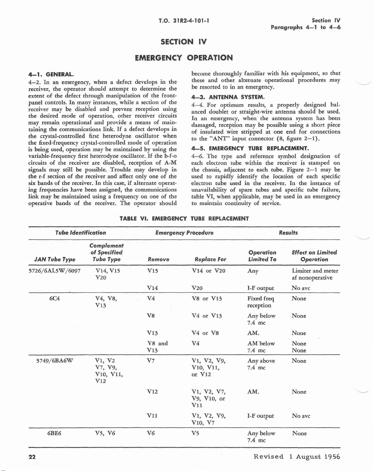
T.O. 31 R2-4-101-1
Paragraphs
Section
4-1
to
IV
4-6
SECTION
EMERGENCY
4-1.
GENERAL.
4-2.
Inanemergency, when a defect developsinthe
receiver,
extentofthe defect
panel
receiver may
the
may remain
taining
the crystal-controlled first heterodyne oscillator
the
is being used, operation may be maintained by using the
variable-frequency first heterodyne oscillator.
circuitsofthe receiver are disabled, receptionofA-M
signals may still be possible.
the
six bandsofthe
ing
link
operative bands
the
operator
controls.Inmany instances, while a sectionofthe
be
desired mode
operational
the
communications link.Ifa defect develops
fixed-frequency crystal-controlled modeofoperation
r-f sectionofthe receiver
frequencies have been assigned,
may be maintained using a frequencyononeofthe
should
through
disabled
of
operation,
receiver.Inthis case,ifalternate
of
the
attempt
manipulationofthe
and
prevent
other
and
provide
Trouble
and
receiver.
a meansofmain-
affect only oneofthe
the
The
TABLE
to determine
reception using
receiver circuits
If
may develop
communications
operator
VI.
the
front-
when
the b-f-o
operat-
should
EMERGENCY
OPE'RATION
become
these
be resorted toinan
4-3.
4-4.
anced
In
in
in
damaged, reception may be possible using a
of
to
4-5.
4-6.
each electron tube
the
used to
electron tube used
unavailabilityofspare tubes
table VI,
to maintain continuity
TUBE
IV
thoroughly
and
other
ANTENNA
For
optimum
doubletorstraight-wire
an
emergency,
insulated wire
the
"ANT"
EMERGENCY
The
type
chassis, adjacent to each tube. Figure
rapidly
when
REPLACEMENT
familiar
alternate operational procedures may
emergency.
SYSTEM.
results, a
when
strippedatone
input
connector (8, figure
TUBE
and
within
identify
in
applicable, may be usedinan
with
his equipment, so
properly
antenna
the
antenna
end
REPLACEMENT.
reference symbol designation
the
receiver is stamped
the
location
the
of
receiver.
service.
In
and
specific tube failure,
that
designed bal-
should be used.
system has been
short
piece
for
connections
2-1).
of
on
2-1
may be
of
each specific
the
instance
emergency
of
Tube Identification
JAN
Tube Type
S726/6ALSW
6C4 V4, V8,
S749/6BA6W
/6097
Emergency
Procedure
Complement
of
Specified
Tube Type
VI4,
VIS
V20
Vl3
VI,
V2
V7, V9, YIO,
VII,
VIO,
VI2
Remove
VIS
VI4
V4
V8
Vl3
V8
and
VI3
V7
VI2
Vll
Replace
YI4
Y20
Y8orYI3
Y4orYI3
Y4orV8
Y4
VI,
or
VI,
Y9, VIO,
YU
VI,
YIO,
For
or
V20
Y2, V9,
VII,
VI2
V2, V7, AM.
or
V2, V9, I-F
Y7
Operation
Limited
Any
I-F
output
Fixed freq
reception
Any
below
7.4 me
AM.
AM
below
7.4 me
Any
above
7.4 mc
output
To
Results
EffectonLimited
Operation
Limiter
af nonoperative
No
avc
None
None
None
None
None
None
None
Noavc
and
meter
22
6BE6
VS,
V6
Y6
YS
Any
below
7.4 mc
Revised
None
1
August
1956
Page 27

T.O.31R2-4-101-1
Paragraphs
Section
4-1
to
IV
4-6
EMERGENCY OPE'RATION
4-1.
GENERAL.
4-2.
In
an emergency,
receiver,
the
operator
extentofthe defect
panel controls.
In
receiver may be disabled
the
desired
may remain
taining
modeofoperation,
operational
the communications link.Ifa defect develops
the crystal-controlled first heterodyne oscillator
the
fixed-frequency crystal-controlled
is being used,
operation
variable-frequency first heterodyne oscillator.
circuits
of
the receiver are disabled, receptionofA-M
signals may still be possible.
the
r-f sectionofthe receiver
six bands
ing
link
operative bands
of
the
receiver.Inthis case,ifalternate
frequencies have been assigned,
may be
maintained
of
when
a defect developsinthe
should
through
many
attempt
to determine the
manipulationofthe front-
instances,
and
and
while
prevent
other
provide
a sectionofthe
reception
receiver circuits
a meansofmain-
modeofoperation
may be maintainedbyusing the
Trouble
and
may develop
affect
only
the
communications
using a frequencyononeofthe
the receiver.
The
TABLE
operator
VI.
If
oneofthe
EMERGENCY
SECTION
using
in
when
the
b-f-o
in
operat-
should
IV
become
these
be resorted
4-3.
4-4.
anced
In
damaged, reception may be possible
of
to the
4-5.
4-6.
each electron tube
the
used to
electron tube used
unavailabilityofspare tubes
table
to maintain continuity
TUBE
thoroughly
and
other
toinan
ANTENNA
For
optimum
familiar
alternate
emergency.
SYSTEM.
results, a
with
operational
doubletorstraight-wire
an emergency,
insulated wire
"ANT"
EMERGENCY
The
type
when
the
antenna
strippedatone
input
connector (8, figure
TUBE
and
within
REPLACEMENT.
reference symbol designation
the
chassis, adjacent to each tube.
rapidly
identify
in
the
the
location
receiver.
and
VI,
when
applicable, may be usedinan
of
service.
REPLACEMENT
properly
antenna
receiver is stamped
his equipment, so
procedures may
designed bal-
should
be used.
system has
usingashort
end
for
connections
2-1).
Figure
In
of
the
2-1
may be
each specific
instance
specific tube failure,
emergency
that
been
piece
of
on
of
Tube Identification
Complement
of
JAN
Tube Type
5726/6AL5~/6097
Tube Type
6C4 V4, V8,
5749/6BA6~
6BE6
Specified
VI4,
VI5
Emergency
Remove Replace For Limited
VI5
Procedure Results
VI4
V20
VI4
V4
V20
V8
VI3
V8
VI3
V8
and
V4orVI3
V4
V4
Vl3
VI,
V2
V7
VI,
V7, V9, VIO,
VIO,
VII,
or
VI2
V12
VI,
V9, VIO,
Vll
Vll
VI,
VIO,
V6 V6
V5,
V5
or
V20
or
VI3
or
V8
V2,
V9,
VII,
VI2
V2, V7, AM.
or
V2, V9,
V7
Operation
Any
I-F
output
Fixed
freq
reception
Any
below
7.4 mc
AM.
AM
below
7.4
me
Any
above
7.4 mc
output
I-F
Any
below
7.4 mc
To
Effect on Limited
Operation
Limiter
af
and
meter
nonoperative
Noavc
None
None
None
None
None
None
None
No
ave
None
23
 Loading...