

GENERAL
PURPOSE
COMMUNICATIONS
MODEL
INSTRUCTIONS
SP-600-JX
RECEIVER
460
West
THE
34th
ISSUE
HAMMARLUND
St.
2 - MARCH
Manufactured
New York
1951
by
MFG.
CO.
INC.
1,
New York,
U.S.A.
GENERAL
PURPOSE
COMMUNICATIONS
MODEL
INSTRUCTIONS
SP-600-JX
RECEIVER
460
West
THE
34th
ISSUE
2 - MARCH
Manufactured
1951
by
HAMMARLUND MFG.
St.
PrintedinU.
New York
S.
1\.
CO.
INC.
1,
New York, U.S.A.

FRONT
SP-600-JX
FIG 1
VIEW
.
INOFC
RECEIVER
ABINET
2
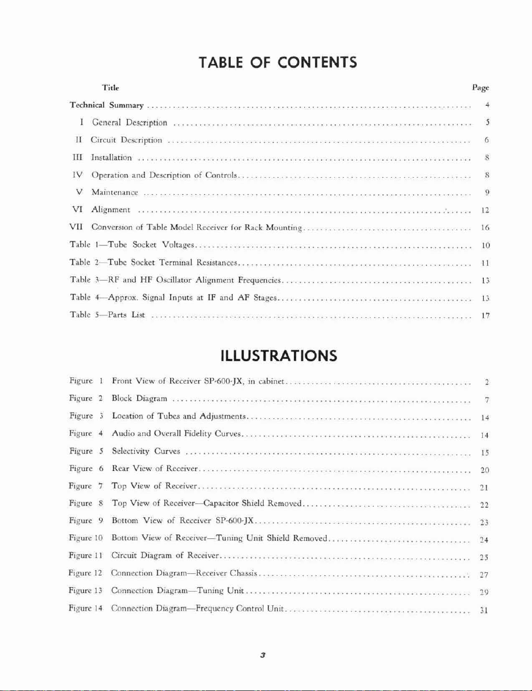
TABLE
OF CONTENTS
Title
T1::chnical
Summary
General Description
II
Circuit Description
II[Installation
IV
Operation and DescriptionofControls
V
Maintenance
VI
Alignment
VII
Conversion
Table
I-Tube
...
....
..
of
Table
Model Receiver for Rack
Socket Voltages.
Table2-Tube Socket Terminal Resistances.
Table
~-RF
and
HF
Oscillator Alignmcm fro:quencics
Table
Table
4-Approx.
5-Parts
List
Signal
lnputsatIF and
ILLUSTRATIONS
.........•.....
Mounting
AF
St;I~CS
.....
.........•...•...............
.•.••.•.•.•••••..•••...•..•.•.
Page
,
5
6
8
9
12
16
10
II
13
II
17
Figure
Figure 2
Figure
Figure
Figure
Figure
FIgure
FIgure
Figure
Figure 10
Figure
FIgure
Figure I:;
Figure
Front ViewofReceiver SP·600·jX, in
Block
Diagram
LocationofTubes
,
Audio
and Overall Fidelity
Selectivity
5
6
Rear VicwofReceiver .
7
Top
ViewofReceiver .
Top
8
9
II
12
14
Vio:wofReceiver-eapaciror
BoHom
BoHom ViewofReceiver-Tuning
Circuit DiagramofReceivcr. .
Connection
ConncctiOn
Connection
ViewofReceiver SP·600-JX
and
Adjustments
Curves
Diagram-Recclver
Diagram-Tuning
Diagram-Frequency
Curves
Chassis.
Unit
Control
cabinet..
.
.
Shield Removed
...
Unit
Shield Removed.
.....
Unit.
3
2
7
I'
14
15
20
21
...
23
24
25
27
29
JI
GENERAL
PURPOSE
COMMUNICATIONS
RECEIVER
MODEL
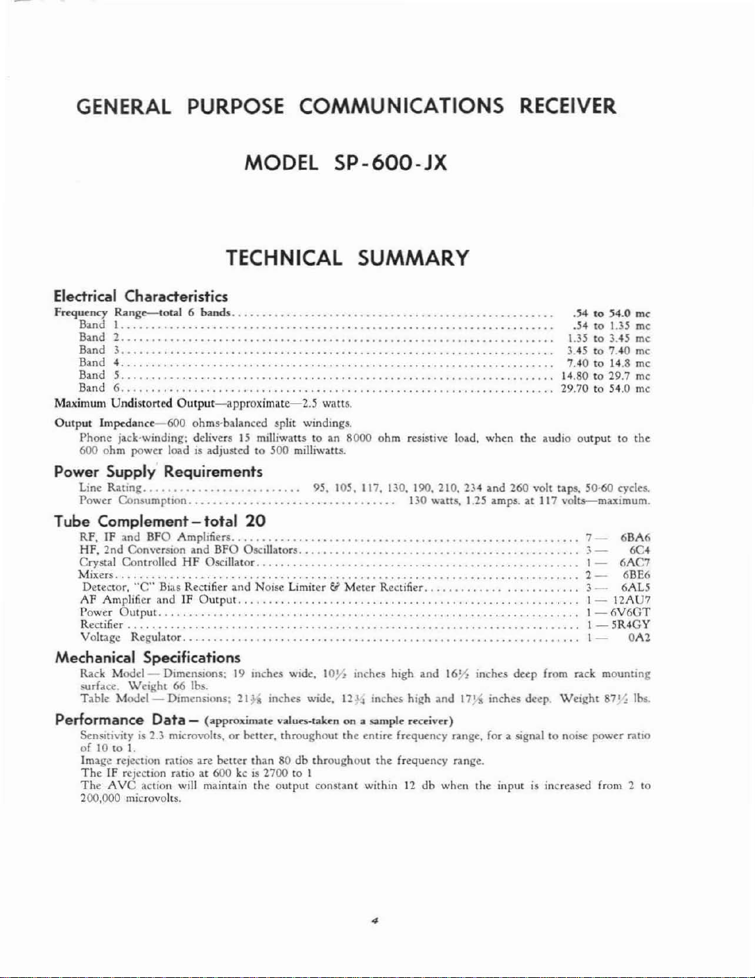
TECHNICAL SUMMARY
Electrical Characteristics
Frequency
Maximum
Output
Power
Tube Complement - total
Mechanical Specifications
Performance
Range--cotal
Band I
..........................••......•••••••...••....•......••.•.••.•.....
Band 2
.........................•.............................
6 bands
.......•.........•....•....•....•....•....•....•.....
Band.\....................•..............•....•....•....•....•....•....•.....
Band
-4
•.....•.•.........••..•.•.••.•..••.••••••••••••••••••••••.••...•.•..••.
Band
5...........................
Band 6
.............................................•....•...•..••...•....
UndistorlW
Impedance-600
Phone
jack-winding: delivcrs
600
ohm
power lood is adjusted
Supply
Line
Rating
Power
COIl5\lmpuon..................................
Output-approximate-2.5
ohms-balanced split windmgs.
1.5
milliwatts to iln 8000
to
.500
waUS.
milliwalt5.
Requirements
_ _. . . . . . . . . . 95, 105, 117, DO, 190, 210, 234
20
RF, fF
and
BFO
HF,
2nd
Crystal Controlled HF Oscillator
Mi:ters
Detector,
AF
Power
Rectifier ,
Voltage
Rack
surface.
Table
SenSItivity is 2.3
oflOto1.
Image rejection ratios are
The
The
200,000 microvolts.
ConversIOn
..............................................................•....
"C"
Amplifier
Oul
Regulator
Modcl-
Weight66lbs.
Modcl-
IF rejection ratioat600
AVC
A.mplifiers
Bias Rectifier
andIFOutput
put
.........................................................•...........
Dimensions:19Ulchcs wide,
DImensIOns:
Data
-
miuO\'olu,orbeuer,
action will maintain
.................•.....
and
BFO O.scillillors ,
(approximate
....................................•..•.•..
and
Noise Limiter &
......................................•...
100
21H
Inches wide. 12.l.j inches
valurs·takt'hona
throughout
better
than80db
kc is
1700to1
the
output
throughout
constant
SP-600-JX
_
.......•.......
. .
ohm
resistivc 10ild,
130 watts. 1.25 ilrnpt. ilt 117 vol1$-mill:irnum.
_ _ .
Meter
Rectifier
..............................•......
Inches high
sample
the
entire
the
within12db
.......•....•............
and
high
and
rect'iver)
frequency
frequency n.nge.
when
when
OInd
....•...••........
160
inches deep from rack
17}i
inches
n.nge.
for
the
1.3.5toi,45
i.45to7.•0 mc
7,40to14.8 mc
\•.80to29.7 mc
29.70to.504.0
the
iludio
260 volt tilpS, 50-60
_
.•......
_ .
,
...•
, .
deep.
Wei~ht
a signal
input
to
nOIse
is increased from 2
.54to54.0 me
.,54
to
1.3.5
mc
mc
me
outputtothe
cyeln.
7-
68A6
.
'-
1-
2 - 68E6
J-
1-
1-6V6CT
1-5R4CY
1-
.
12AU7
mounting
87'~
power
6C.
6AC7
6ALS
OA2
lbs.
ratio
to
4
GENERAL PURPOSE
GENERAL DESCRIPTION
COMMUNICATIONS
RECEIVER
The
SP·600-]Xisa 20 tube Radio Communications
Receiver
with
self contained
power
supply.
The
JX
suffixinthis model number denotes that this receiver
is made
the
tors
values and tolerances
ferred value listsorwhere
permit their use.
equal
steel, tanle model cabinet finished in
plement
in a
opcntion
ing
primaryisprovided with taps covering a line voltage
range
iF
speaker receptionofAM
~raph
over
in
control knob. on
frequency
a small front p.lncl window indicates
hand
indi..:ator with
has
band
scales Over each frequency
r:\tc
sign
ccptional opcrating case. It controls
and
provides extremely close calibration accuracy and completely accurate resctlbility. A
positi\·e locking
setting.
main dialis50 to I and
dial to
to
theRFamplifier.
in
accordance with
exceptionofthe
where
special design considerations require special
useofa few capacitors
The
or
su~riur
The
receiverissuppliedineither
the
standard19inch rclay rack.
The
self contained
from a single phase. 50to60 cycle
current
from 90 to 270 volts.
lighter
power
to
~rcy
source.
JAN
nm
includedinthe
space limitations do
specifications.
and
JAN
special componclHs so used arc
the
JAN
componentsinquality.
a well vcntil:l.tcd
dark
front
panelorfor mounting
power
supplyisdesigned for
The
The
grey to com-
power
power consumption
ahemat-
transformer
no watts.
The
receiverissuitable for
or
AM
MCW
The
standard
a frequency range from 0.54to54.0 megacycles
sill:
bands.
1Il
u~e.
In addition to
an arbitrary
spread dial provides continuous
logging
The
single tUlling controlislarge andofspecial de-
to
permit ma:<immn traverse speed as well as
band
The
tuning
the
An
ingeniously designed rotary turretisemployed
change
modd
The
lar~e
the
band
and a
This
control also aligns
the
pr()pcr dial scale.
the
~::tle
and
resctability.
spread dials.
action
ratio from
maiJl
dialis6 to
bands and to place
Mixer
either
radio telephone,
telegraph signals.
provides continuous coverage
eHily
front p.lncl, selects
band
frcqucnc}'
which in conjunction with
An
without
the
the
ratio from
:lnd First
headphoneorlouo
operated
indicator visible
the
scal..:.s,
band
f{lr
anti-backlash gear train
tuning
affecting
tuning
1.
the
coil assemblies
Heterodyne
CW
band
the
through
the
frequency
dial frequency
the. main dial
band
clI:tremely ::tccu'
both
the
lock provides
the
frequency
control to
the
band
with
resis·
pre-
not
tcle-
change
desired
the
sprcad
e:<-
main
the
spread
Oscil·
lator stages directly adjacent to
tionsofthe
spccti"c tubes.
high signal to noise ratio.
Two
arc provided on all bands.
version,
cludes a mixer, h.:terodync oscillator, fnur stages
IF amplification, detector and
limiter and meier rectifier. beat frequcncy
be;ll frequcn.:y
and
fier
cOllversion. employed for frequencies abo\'!': 7.4 mega·
cycles,
dyne
system includes
,I
voltage regulator_
The
nel crystal controlled operation on any six frequencies
chosen within
comrols permit
ity continuously
selected fixed fretjuency signals. F(lr crystal controlled
fixed channc1l)pcr:Hion
dial to
quency desired
trol. Nl) retuningofthe
desirable,
tion for
not supplied with
chased
MFG.
It
is
til (unction.
The
rdative
microvolt, when
g;lin cOlltrol ;ll maximum. A re,lr .:ontrolisprovided
for adjl.1stmcnt at
RF
signal
panel meter switch
cates
watts. A
the0db
The
constants for
quency oscillator employs a hIgh cap,lClty Colpitts circuit which
and minimizes oscill:llOr harmonics.
quency oscillator
tcctor
of
oscillator lock-in.
tune
four
gang
tuning
This
assures mall:imum sensitivity at
stagesoftuned
uso.:d
011 frequencics
buffer ;lmplifier. IF
output
include,; a second
crystal controlled oscillator.
frequency control unit provides for fixed chan-
the
CO.
two scale
the
through
signals sharplyto:cro
a B powo'r rectifier, C bias rectifier and
the
the
signal frequency, switchtothe
and
when
swit.ching (rom
the
same signal frequency.
on
special
specifying:
strengthofthe
input
of
audio
output
rear controlisprovided for adju.stlOent
reading.
AVC
circuitisprovided
CW
gives a high
radio frequenc}' amplification
powcr
stage.
rangeofthe
sele.:tionofthe
variahle lUningoreitherofthe
itisonly nl:ccssary to set
tunc
with
the
rCCclvl:f,
order
the
tuning
meter
r..:ccived signalindb
operatcd
the
plus 20dbscale reading with an
10 mi.:rovolts.
the
lower scaleofthe
power levelindb
and Mew(lperatioll.
vollageisintroduced into
a buffer amplifier which eliminat.es
This
feature mdkcsitpossible to
their
capacitor
The
circuit for single con-
upto7.4 megacycles, in-
AVC
output,
The
drcuit
m;lI:cr
and a second hetero-
The
ro.:ceivcr.
normal
the
delt,1
main
tuning
VFO
These
but
from
signal frequency for which
on AVC;\110
HAMMARLUND
11I1rm.dly
011
with
ordcroffrcquency stability
beat
and
respective 5ec'
and
their
re'
oscillator,
ampli-
stabil-
six
the
con'
the
from 1
the
RF
beat fre-
beat fre-
lhe
dc-
the
in-
of
or
rectifier, noise
A.F
for double
power supply
Front panel
hig:h
crystal fre-
frequency
is necessary
to crystal opera·
crystals arc
shnuld be pur-
lIlclk,ltes
with
depressionofthe
metcr indi-
from 6 milli'
s.:par:ltc time
The
The
permits
of
5
dusionofthe
lator lIlJecrion
fUnd control varies
to plus
The
ference
type
nOI~.
rear control for ;adjustine
to
suit
opcr.umfZ"
the
or
rnmU5
nni~
limiter circuit effectively hmits
audio
3 KC.
.:onditions. A front
Ix.t
from ic:nition systemsorother
The
hmitcr
SWItch
permits optional usc of
the
beat ascii·
frequency from 0
the
inter·
.soUft:esofpulse
the hmlter.
The
antenna input
a halanccd
100
COnventional
The
load (lr
wllldlrl~
Ime.
ohms.
The
STOgie
audIO
output
Illle
andisprovided with a four terminal spilt
for balanced load oper-ttiOIl.
power outputISapproll:imatcly
phone circuit whell referred
vides
si~nals
the 600 ohm
;"tlcnuated apprOll:imatcly15dl:-
power output.
AnRFf!ain
trolofsensitlvityInthe
cirCUliisduiJ,.:ned for
Thc
mput ImpedanccISnominally
USl:
receiver may alsobeoperated with
wire antcnn,l.
circULt
IS
tle~IJ:JH:d
for a 600 ohm
Undlstoncd
2.5
W;lttl!.
the
(111m
manual
The
load pro-
to;'1I1
ROOO
conlrolisprovided for
prescnceofstrong signals and
wuh
head
helow
COil'
CIRCUIT DESCRIPTION
GtntralFigure
more
the
various Circuit sections.
ous tubesisshown in Figure J.
conversion.
consistsoftwo staJtesofRF amplification
First
MotU
stagCllofIF
Detector and
Beat Frequency
amplifier
Y'J?
Power Rectifier Y-19, e Bias Rectifier
age Regulator V-JB.
In the circuit for double convcrsion. used fnr signal
frequencies above
Second Heterodyne Oscillalor Y·S are substituted for
the Gate tube
Input
to provide optimum coupling from
miMion
tenna maybeused.
RF
lurretisemployed to change bands and to place the
COli
as-~mblies
Y·5
and First Heterodyne Oscillator V·4 stages di·
rectly adjacent to their
gang tuning capacitor and their respective tubes. ThiS
assures maximum sensitivity at high signal to noise
ratio.
Firsf Heterodyne
The
rotary turret band change swilch, advanced de·
The
11. A block diagram. Figure 2. is provided to
circuitisshown schem;atie:tlly in
deilfly show [he arranflemen[ and functions
The
locatlonofthe
The
circuit, for single
used for sienal frequencies up[07.4
V·I
van'
me
and Y·2.
Y,S. First Heterodyne Oscillator Y-4. four
amplification
Aye
Oscillator
Y·16·A
and Y-16-B. OutpUt Power st'age
rectifier
Y'?,
Y·9.
Y·H.
Noise Limiter Y·15.
Y-n.
IF output :md
Y·IO and
Y-li,
AF
and the Power Supply system which includes B
Y·20
and
Yoh·
7.4
me. the Second Mixer
Y'6
and
Y-?
Coupling -
Ime. A M.laneed doubletorstraight wire
Amplifiu-An
The
antenna couplingisdesigned
ingeniously designed rotary
of
theRFamplifier
respeetiv~
O.scil1ator_ (Variable
;a
100 ohm trans'
Y·I
and
Y·l,
SC.:tl(1115ofthe
V4)-
an'
Mixer
four
tlper-lles
The
but
Ic,Ixcs
tlon
~twccn
on either
scnd
the
MANUALorAye.
rc':CI\'O::
switch
dl:5Cn~ltl:es
poweronto provide for mstant recep'
transmissIOn pcmx!s.. A re,lr
proVides for the connectiunufan external rela)'
Radiation
ments for .!lhlpboard
is
negligible :lIld complies with
OflCr:lIIOn
and for multi·rccclwr
insullations.
Frequency drift
ranges between
;a
quency depending on
vcry
unusual
tuned
HF
after aISmlllute warm up pcmx).
.001
percent and
the
frequency u$:d.
.01
dCj.!fCeoffrequency stability for \'an,lble
oscillators and
dosd}'
appro.1.chcs crystal
.!ltabllity.
The
selectivity control pro\'ides three degrecs of
crystal and three degreesofnOll'cryst:11
ranging
crystal tiltcr embodies
have provcd so effective
Super
from sh;'trp (.2kc)
Pro
Recei\'.::rs. incorporatedinan improvcd
the
OInd
tl)
S,IIllC
deSIrable
broad (13.KC).
Circuit fealures that
mechanical design.
II
Signofthe four gang, twm section. \'anable tunlllg
capacitor and
Vide
of
frequency stability and dial calibration accuracy
to a previously unattained degree.
First Heterodyne Oscillator - (Crystal Controllrd
V.j)
_ For services requmng extremely stable.
frequency operation. a crystal controlled high fre·
queney
variable to crystal controlled
of
silt
crystal positions.iseffected by a front panel con'
trol. A
of
the
crystal oscillator frequency over a plusOfminus
.005 percent range.
Intermediale Frequency Amplifier - Single cOllver'
sion to 4S5kcis
low
7.4
incorporating
circuit. Six positions
widths
narrower bandwidth positions, th.:
IIpcratlQl\
treme
SCIC':I1\·lty
,tdJ.cent lllierfermg sign:lls.
Double conversion
des
alXl\"c
mebythe
Y'4orY'3 for high Image rejection.
signalisthen
Mixer
Y'6
Oscillator Y·B, for selectivity.
Detector and
high
levcl Detector and
euit
is
provided with separate time constants for
and Mew operation.
rug~ed
construction throughout. pro'
oscillatorisproVided. Instant
oscillator. with a choice
.second front panel control permits adjustment
employed for signal frequencies be'
mc.
There
arc four stages of IF ampltfication
the
Hammarlund patented crystal filter
of
of2•.5,1.3.
scl~etivlty
:..
Sand
prOVIde
13
kc.
cry9.,,1
The
.::rystal
7.4
me.
ph<lsmg
for
tho?
is
employed for signal fre.quen'
The
signalISheterodynedto:;.955
.:ontrol
high :lttenuallooofdC1SClr
First Mixer V·S and Heterodyne Oscllla!Or
heterodyned to 455keby the Second
and the
3.05
me Fixed Crystal Controlled
AVC-The
Aye
Y,14 tubeisused as a
RectIfier.
the
receiver
re.:ept'Il.:le
requir~
pcr..:enr of fre-
ThisISa
.selectivity
The
ill
Hammarlund
fixed
ch"n~eover
from
6 db band·
On
the thre.:
filta
IS
395S
Aye
III
ex
me
cir·
prOVides
The
The
CW
6

Beat Frequency Oscillator -
oscillalor employs
gives
a high orderoffrequency stabIlity and minimiz.es
oscillator harmonics.
Y-I
3. is coupled into the detector circuit through Buf·
a high capacity Colpitts circuit which
The
The
beat frequency
beat frequency Oscillator
fer Amplifier Y-12. which eliminates oscillator lock-in
and permits
meansofa eOlllrol
A
frolll Panel control varies the audio beat frequency,
from
Noise
limits the noisc interference from
Other
vuiationofthe beat oscillator injection by
[l1catedonthe
"era beat to plusorminus 3
Limiter-The
noise limiter circuit Y-15,
rearofthe ch;lssis.
kc.
ignition systems or
sourcesofpulse type noise. A separate control
,,~
Clll'$TAl CONrllOllEO
Power Supply -
part
of
the recei
The
...
power supplyisan imegral
'er. It includes the B recnfit'r
Y'19
and the C rectifier Y-20, together with their respective
low pass filters and the Yoltage Regulator Y·IS.
The
power transformer is provided with screw terminal
primary taps, covering a power line source range of
90
to '270 volts, 50 to 60 cycles.
former
is
protected by a fuse in the primary circuit.
Tuning
MelCr-
The
tuning meterisusedonAYC
operationtoindicate thc accuracyoftuning and
The
power trans-
the
relative strength of received signals. DeprcS5ionofthe
Meter Switch converts the meter
of output level
IF
ill
db from 6 milliwatts.
outpur
circuit for indication
''0
c
REcr
,BLOCK
DIAGRAM'
""
f1G.2
switch S-6, permits optional useofthe limiter on an)'
mode of operation when pulse type
present.
Audio Frequency Amplifier - A resistance coupled
amplifier triode Y·16-B. amplifies thc
signal from
Audio
the detector.
OUfpul-The
audio
transformer coupled through a split. balanccd wind:ng
to
deliver
2.5
load.
The
watts undislOrted output to a 600 ohm
split balanced winding pcrmilS balancing
the direct currelltinthe Output circuit,asused for
teletypeorsimilar service. A separate secondary wllld·
ing provides attenuated audio signal output for headphone operation.
This
winding
of15milliwatts inro an 8000 ohm resistive load when
the 600 ohm power secondary
watts
to a 600 ohm resistive load.
IF
Outpul-
A cathode follower Y-16·A provides
is
a low impedance source of intermediate frequency
(455 Kc) signaltothe connector on the rear skirt
the chassis.
interference
audio frequency
output
will
tube Y·17.
deliveranoutput
delivering 500 milli·
",
a
5R4GY
is
RECT
II
REG
'"
0"
---
............
Sl9nQI
II'lT~
5'9"'" pot!>
e,,"'"wm
fGI'
• •
frfll~1ICj
RF Gain Control and Power Switch gain controlisprovided for manual controlofsensi·
ti\.ity to prevent overloading on strong signals when
opcratin2 with
"MANUAL"
when the switchisin
··ON-OFF"
the
AYC·MANUA.L
position.
the"
This
AVC"
comrol
position.
switchisoperated at the counter-clockwise
extremityofthe RF gain control.
is
Send·Receive S
.....
itch -
The
send-receive switch dc·
scnsitizes the receiver but leaves the power
provide for instant reception between transmission
of
periods. A
receiver for the
rl!ceptacleisprovided on the rearofthe
extental connectionofa relay.
Convenience Outlel - A cOllvenience pOwcr outlet
i1>
providedonthe
tion
of
an :lccessory such as a lamporelectric clock.
rcarofthe chassis for
Radiation - Advanced design and shielding
high frequency, second conversion crystal
frequency oscillators
negligible point so
of
common in multi·receiver installations,
'has reduced radia'tioll to a
that
interferenceofthis nature,
a minimum.
ft>
""
f"Q~ne;n
••
obG';.
7.4""
b.'o...
7.4
The
switchinthe
al.so
operates
The
Power
"on"
the
connec'
of
and beat
is
reduced to
me
RF
to
the
7

INSTALLATION
Tu~s
and
all
tubes
any p;lckingisremoved from
Power
lead on
transformer tap which most nearly agrees with
to 60 cycle power source voltage.
Anlenna-The
terminals
hne.
The
WIth
the
meter,
be
used with a bab.nced
deSiredtooperate
leona
of
the connector plug and a
connected from
Packing-Inspect
are:
firmly in their respective sockets ;md tha.t
Supply-
the
is
designedtomatch
angle plug
receiver, is designed for use with a small dia-
"TWINAX"
lud·in
Make sure
power tri!.l1sforrner is connectedtothe
input
adapter
tr.tnsmission Ime, which should
with
the
a smgle
other
wire should
the
chusis
the
receIver.
that
the
primary tap
impedanceatthe
OJ.
100
ohm
and connector. supplied
antenna
wi~
be.
connectedtoone
ground
terminal of
transmission
Installation.
antenna. the ;m-
lead should
the
to
connector
III
see
that
the
antenna
If
it
tcrminOlI
50
be
plug
to
;l.ntenna
Speaker -
manent magnet dynamic typt: and should include a
speaker voice coil to 600
former for connectiOn to the 600
terminalsofthe receiver.
Headphones
phones maybeused in
pedance typeisrecommended.
CilIOOatthe
is
Mounting-The
or
mountedIna
IS
purchased.Itis
cabinet shouldbeplaced in a position which permlU
the free
IV
OPERATION
the ground terminal. whIchisadjacenttothe
input receptacle :u the
The
loud spea kcr shouldbeof
- Either low
lower left sideofthe front panel.
receivcr maybeplotcedona tahle
~D.ndard
supplied
accessofair for
reuofthe
ohm
linc matching traIl!-
or
the
hi~h
phone jack.
The
19
lOch
nll'k.Ifa table model
WIth
a steel cablllel
the
ventilation louvers.
tumng
the pt:r-
ohm
audio
output
impedance head·
The
phone jack
high
unit.
1m·
IS
The
10-
DESCRIPTION
The
front panel dials
Figure I and
als
are
Tuning
band
frequency band
arbItrary,
bItrary. 0 to 100. scale
p,.,inter
lutions thilt
at any
scale.ofthe main dial indicates
the
bitnd spread dIal indicates 87.6. the reading to
lor
this settingISread. 487.6.
hand spread
dIal
over
band
tlOn
pomts.
slons.onthe
quency
tings. ThIS permits extreme i1ccuracyinthe logging
stations.
Crystal Controlled
on fil(eJ frequency chilnncls the
CONTROL"ISprovided.
plied with the receiver, hut will be supplied on special
order. In
frequency operation crystal units should be ordered
from
order
each unit
has provision for
the
shown10FIgure 6.
spread dialisto
of
setting
spread divisions. with
hand into itpproximately 6000 readilble set-
HAMMARLUND
should specify the signal frequency. for which
rear chassis skirt controls ilnd termin-
Dials -
scales, calibratedinmegat:yclcs
outer
scale.
the main dial indicates the
have been made by
Thus.ifthe
system divides
each frequency
SlOceitis
I»nd
ordertoinsure correct crystal controlled
is
tobeused.
and
controls
The
milin diiil is to
the
right.
The
band spread dial has an ar-
The
numernl under the fixed
pointer, for the
This
the
band
into approximately 600
one
easy to estimate
spread
snle,
HF
Oscilla.tor -
The
MFG.
The
six
crystals. Variable frequency op-
frequency control unit
ue
shown in
the
The
the
over
rotationofthe
half
thLS
crystals are not sup-
CO.
left and
main dial has six
numberofrevo'
band spread dial
the figure 4 and
precise mechanical
division calibra.-
one
tenth
divides each fre-
for
"FREQUENCY
INC.
the
and
outer
main
dIVi-
operntion
and the
an
lol,!
of
OF
CONTROLS
crationorcrystal controlled frequcncy operation on
anyofthe
"CRYSTAL
sIgned for
10
the rnngeofthe
"DELTA
very small plusorminus frequency toleranceofthe
crystals.
The
tion should be as follows: Loosen the knurled
screwontopofthe crystal unit and push the retainer
spring assembly to
stals in
l'Ctainer spring assembly
press
thumb
each crystal
chart provided for this purposc alongSIde
switch.
IfItis
numerals on the chart shouldbeused!Othat
agree with the numerals on the crystal socket positions.
which
main
for which oocration
should be
number
Delta Frequency control should be adjusted for m:tximum
nOled
quency control must
nal frequencyischanged
should
six
crystOlI
SWITCH".
uSC!
WIth
FREQ" controlisuSC!d
procedure for crystal frequency control opera-
the
crystal sockets, numbered Ito6.
on
top of
screw. Mark the
was selected. in megacyclesonthe plastic
PenCilormk maybeused and can be ernsed
desired to
are
tuning
for that
si~nal
that
be set to agree with
change
also indicatedbythe crystal switch.
dIal should be set at the signal frequency
set at the pOsition corresponding to the
or
for
this luning adjustmentofthe Delta Fre-
positionsissclected by the
The
crystal
suitOlble
receiver
the
the
si~nal
2.ero
crystals at
Olbo".::
reu.
lnscn
fOl"\ollard
cryst41 holders and tl.ghten the
sign:lll
these figures at any time.
IS
desired.
frequency on the chart.
beat as required.
be made each time
and
that
the
OSCillatorisde-
;)Iny
one
megacycle.
to compcns..lte
the
crystal or cry'
so th;n the sprinc:s
frequency for which
The
crystal switch
It
that
the main tuning dIal
new signal frequency.
frequency
Bring the
the
~hould
The
for a
thumb
crystal
The
they
The
The
the
be
si~
"

Tuning
right of
for the tuning
quency
shlflln~
under:"
Tuning
left
sljtnal
strength
The
chassis proVides adjustmentofthe plus20db
on
pressionofthe
meur
I~vcl
returned to
and should
the
pili,
observe this precaution may re<ult
meter.
Lock -
the
The
tumn~
tumng
knob, ptovidcs a posillVC locking
lock, located to the
me.:hamsm without affecting the fre'
settmg.
whenitIS
of
the
tumO(::orwhen the receiverisoperated
clesLrt~d
tl)
prevent accidental
severe conditionof'I.-ibration.
Meter-
on
the
front
and provides
of
the
"METER
The
pand
rccel'l.'ed
AD)
RF" ,:ontml at
tunmg metcr at
15 useful m
;m
mdic.ition
signalinclb
a..::curau:ly
of
the
tunm~
relativc
from I microvolt.
the
rearofthe
the
upper
readmR
theRfscale, with a10microvolt input signal. Dc,
"METER
SWITCH" co",,'ercs
the
circuit for Illdlcatl0noftheAFoutput power
in
t1b
from 6 mllhwaltS.
theRFscale
110tbedepressed for Ihe
audio output has
bC1'1i
This
cirCUlt
switchisspring
pnsition when released
adjuslcd for
AF
scale ulIlcss
10",
po",cr out-
by meansofhcadphonesorspeaker. Failure
ill
The
"METER
AD)
AF"
dama~e
control at
the
10
rear
the
the chassis proVides adjustmentofthe 0dbreading
theAFscale. which should be made when theAFout·
put
power from the
6 milliwattsor1.9
Band Change -
600
ohm
,lUdio
voll.5
acrOM
Th~
large knob, to the left.isthe
output termllldls IS
:l
600 ohm load
band change 1.'0ntroi. Each revolutionofthiS control
turns
the
turret.
COIl,
tnmmer
and
SWlt.:h
frequency band to the
contilimn,l:l
and
m<lY
ble
turned
11\
tive detent machanism
various bands.
ously
operates
at
the
centerofthe panel and aligns
indIcator with
Selectivity Switch
The:
the
small frequency band dial, located
the
proper scale.
-
theRFandHFoscil1uor
cont<lct
neX[.
either
<lSsures
<tsscmbiic.s,
The
turret has no stops
from one
direction desired. A
correct locationofthe
po.!Ii-
band change control simultane-
the
dial frcquenC)f
The
selectivity switch provides
three crystal and three non-crystal degreesofsclel.'tlvity. ranging from extremely sharp, for
tlOn.LObroad for good fidelity
control knob
di;ll
indicates the 6 db band width at each
MCW
CW
opc.r,luon.
recep'
The
setting.
Phasing Control -
The
phasing control permits
hlllh attenuationofclosely adjacent channel interference
on
either sideofthe signal frequency. when
the
crystal selectivity positions are used.
Beat Frequency Oscillator
os..:lll,ltoristurned
tht:
"MOD-CW"
"on"
SWitch.
for
- The:
CW
The
1>£at
si~na.1
frequency
operuinn
heat frequency dial
of
(In
by
l>houldbeset at
adJum:d to
quency
"BFO
pend..ntofother
tl'nua.ung
a
pulse
OSI:llIator
IN)"
No~
.ype
z.ero
for
tunin~
to
-,!,i"e
the
desired audio pitch.
inJection '·olu.gc is
controlonthe
Limiur-The
nolSC
mterference from ignluonorsimilar
noise limiter switch i
controls
a.ndisuseful10e:rca.t1y
l.ero beat and then
;p.dJostablchythe
rt:;1r
skirtofthe
sources. regardlessofthe modeofopera-
tion.
Send-Recdve -
The
send·receive switch permits
descnsitl:ing the receiver during transmission periods.
to prevent damage
proximity
to
to the receiver. when operated in
the lransmitter ;\nd provides instant
turn to reception between transmission periods
Relay
to
rear
of
l>cnd-rcceive
an
the receiver.isconnected in
switch ;\nd provides for the connl;ctiorr of
externally connected relay. to perform
receive
operation.
receive switch is
A VC-Manual Switch -
Receptacle -
pi'rmlts the
Ity
Oper.ttlOIi
chOiceofeither
as desired.
The
When
left in the
relay receptacle.
the relayisused
"open"or"scnd" position.
The
AVC-Manual Switch
AVCorManual sensillv-
The
AVe
which insures maximum sensitivity for weak Signals.
RF Gain
adjustmentofthe
suength.
tion.
Justed
mg_
on
AVe.
to reduce
transmission
Siredtouse
signal
Control-
TheRFgain contrlll
sensitivity for signalsofvarious
when under the
in
ordi:T th.u the receiver scnsitivit)· may be ad-
to
SUit
This
the Signal strength and prevent owrload-
controlISalso in the
III
order
that
undCSll'<Ible
of
the received
the
tunin~
"manua'"
cirCUli
the
senSitivity may be
nOISC
dunng
"off" periods
si~nal.
meter fllr indicationofrc!atn·c
strength. the RF gain control shouldbeat maxI-
mum.
Audio Gain
JUSts
the audiO input to the audio
Control-
The
audio galll control ad-
>tmpldier
should be adjusted for the reqUIred audio
operating
whell operating 011
of
quency source IIlput to the
provided on
mg
on
AVe
andisnest left:nor ncar maximum
MANUAL
Phono Input - Termmals
the
n;cclver for phonographorother
arc provided on the rear
audiO
Convenience OUllet - A
the
an accessory,
rearofthe receiver chassis for operat-
!Uch
as an
pow.::r
dectne
contro!'
frequency a.mplifier.
outlet receptacle
dockorlamp.
The
heat fre-
chassis_
lOde-
at-
re~
on
paralh::l
wHh the
the
scnd·
the
send·
the
has a dcldy bias.
prOVides
opcratlllg condi-
when Opeutllll::
adJu5h:::d
III
WhenitIS
the
dc'
tube.
output
when
audl() f
reo
It
is
MAINTENANCE
This
should normally require
socket voltages and resistances should be measured to
.:hassis.
shown
receiverISdeSigned for continuous duty and
httle attention beyond the
replacement of
velop that
tubes. However, should trouble de-
c-a.nnotbeeliminated with new tubes, the
Any
;\PPTf'l.'iable
departure from the values
in tables 1 and 2 will generally indicate the
9
V
L-omponentorcircuit at fault.
Opcratinf[
~reatly
and maintenanceofthe
facilitatecl if the contenlSofthis instruction
m;\nual are thoroughly dit;ested. Approximate lIlput
signal values
III
table
for
stajZehy!ta.$tc
4.
rccel'l.·er
gain checks arc shown
will
be
TUBE
SOCKET
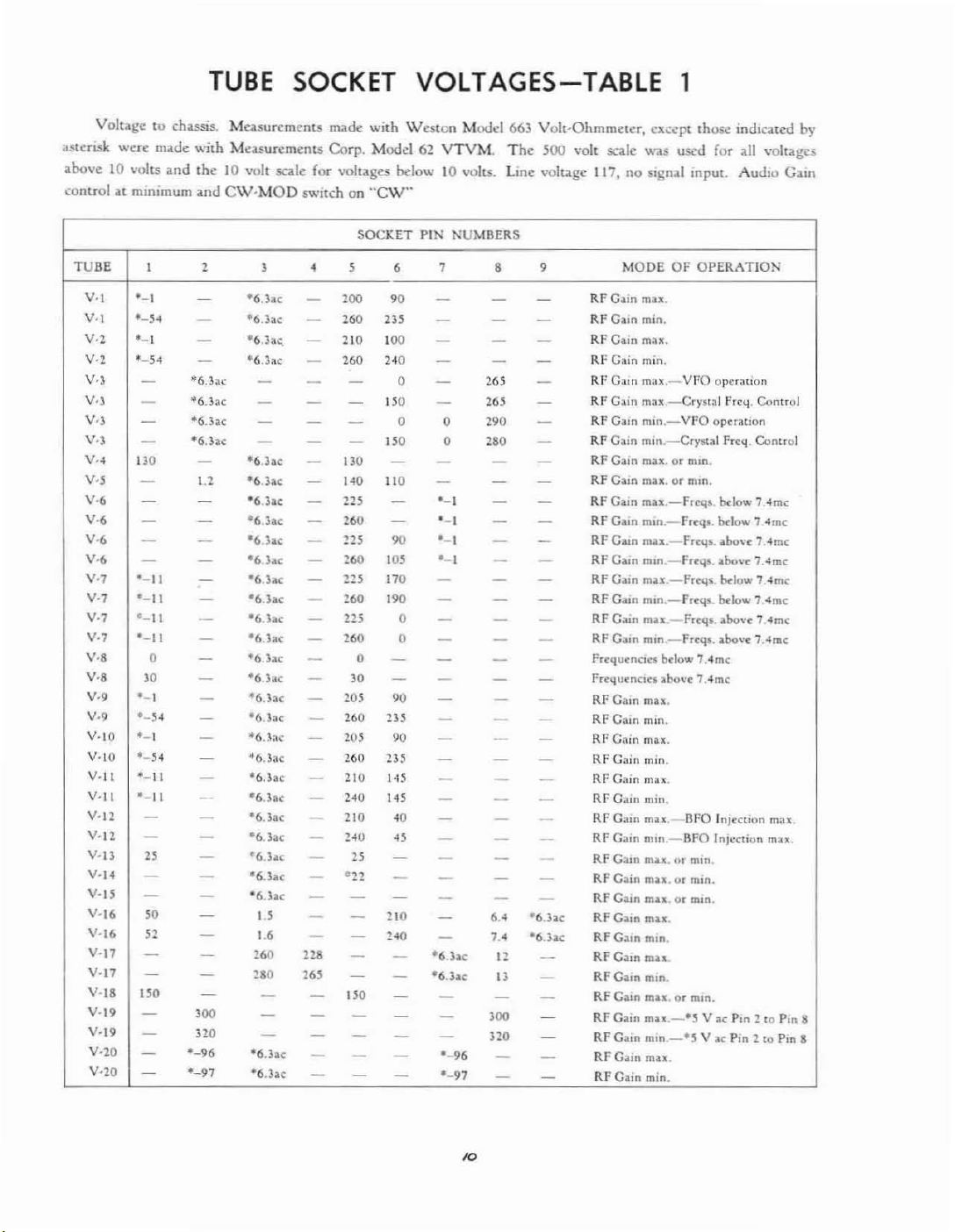
VOLTAGES-TABLE
1
Volu,gctochusis. Ma.surements
<Istcflo!k
above 10 volts iilld the10volt scale (or voluges below10volts. Lme \'Oltagc 117, no signill
,,:oolrolatminimum and
were milde with Mca.surcrncnu Corp. Model 62
C\V-MOD
TUBE
V·I
V·I
V.,
V·,
V.,
V·,
V.,
V.,
V·.
V·,
V
.•
V·.
V.,
V••
V.,
V·,
V·,
V.,
V.,
V·,
V·,
V.,
V·IO
V·IO
V·II
V·II
v·n
v·n
V·13
V'14
V·iS
V-16
V'16
V-11
V-17
Y·18
Y-19
V-19
V-lO
V-20
I 2
'-I
·-5~
'-I
·-5-1
-
-
-
-
130
-
-
-
-
- -
'-II
'-II
'-II
'-II
0 -
'0
'-I
'-54
'-1
'-54
--II
'-II
-
-
"
-
-
'0
52
-
~
"0
-
-
-
-
-
-
-
-
·6.h.c
t6.hc
t6.h.c
-6.h.c
-
l.l
-
-
-
-
-
-
-
-
-
-
-
-
-
_.
-
- '6.3loC
-
-
-
-
-
-
- 280
-
'00
no
'-96
'-97
,
-6.3ac
·6.3:1.<:-
-6.1;0.,
·6.33C
- -
- - -
-
- - -
-6.);&c
t6.3ac
-6.hc
'6.lac
'6.lac
'6
hc
-6hc
'6
lac
'6hc
'6.3at
'6
lac
'6.3:.c
'6.lae
'6.3:.c
'6.3:.r
'6.3ae
'6.3:.c
'6lar
'6.lae
e6
hc
'6.hc
·6.hc
Il
I'
260 228
-
-
- -
'6.lae
'6.31oc
m.de
with
SWitch
on
"CW"
SOCKET
,
•
'00
-
260
-
- 210
'60
-
- 0
- -
- 130 -
1<0 110
-
ns
-
-
'60
225
-
'60
-
225
-
260
-
215
-
260
-
0
-
'0
-
205
-
260
-
105
-
260
-
210
-
240
-
210
140
-
"
'22
-
- -
-
- -
~
-
-
~
2"
-
"0
- -
-
-
- -
-
-
Westen
PIN
•
'0
III
100
1<0
ISO
0
ISO
-
-
90
10'
170
190
0 -
0
- -
-
'0
235
'0
235
'<5
1<5
.0
<5
-
-
HO
'<0
-
-
-
-
-
-
Model 661 Volt-Ohmmwer. except those indIcated by
VTVM.
NUMBERS
, , ,
-
- - -
- - -
- -
-
-
0
0 280 -
- -
-
'-I
'-I
'-I
'-1
-
- - -
- - -
- -
- -
-
- -
- -
-
-
- -
- -
-
-
-
-
'6
he
'6.3u
-
-
-
'-96
'-97
The
500
..-olt
- -
-
265
-
-
2"
290
-
-
- -
- -
- -
- -
-
-
- - RF
-
-
-
-
-
- RF
- -
-
-
- -
- -
-
-
- RF
-
-
-
'6.3lo(
•••
,
..
'6.3..(
12
-
13
-
-
-
'00
-
~
520
- RFGlom
-
-
-
scale "''as used for all "'oltagcs
MODE OF OPERATION
RF
G:lIn
max.
RFG~m
min.
RFCam
mn.
RF Gain min.
Rt'
G;o.m
max.-VFO
RF
Gam
mn.-Crystal
RF O,lIn
mm._VI'Q
RF
Gam
mm.-Cr~·5tal
RF
Gam
mn.ormm.
RF
Gam
max.ormm.
RF
Gam
mu.-Frc'ls.
RF
Glom
m,n._Frc'l"
RF
G:un
mn.
RF
Gaon mm.
Gam
mu.-Frrq,.
RF
Glom
mon.-frrqs..
RF
Gammu-Frtqf.
RF
Gloon
mm.-Frrq5
FrrquenclCf below
freqUtnen:f
Rf
RF
RI'Cain
RF C;lln max.
RI'
RF C:l1n max
RF
RF
RF
RFCa,n
RF
RF
RF
RF
RF Gain
RF
RFGalll
Glom
Glom
Gain
Cain
Gam
C.un
Gloin
Glom
Cain
Glom
Gam
Gain
Gam
lobovt 7.-4mt
mu.
mm.
mon.
min.
min.
nun,-BfO
mu."rnun
max.ormm.
lOU.
mu.
min.
mu
mm.
ronormin.
mu-'S
mm.-'S
mn.
min.
mpu!.
Audlu
operatlon
fretl.
operation
Frcq. ContrQ[
bc-Iow
1.4mc
b<low 7 4mc
FrclI,.loixwc 7.4mc
Frrq$.lobovr 7.-4mc
brlow 1 4mc
b<low 1 4mc
abovc 7..4mc
...
bolle 7.4mc
7.4mc
nro h1ltetion max
Inll:CllOn max.
or
m,n.
YI(Pon
2 toPmII
V
loe
Pin
2[0Pm
G:am
Control
8
10

TUBE
SOCKET
TERMINAL
RESIST
ANCE-
TABLE
2
Resistancetochassis. MC,l.Surcmcnts
Tub.:. removed from socket under Illcasurcm..:m.
mum.
Pin No.
Limiter
Socket
Tub.::
Socket
V.,
V·l
V·3
V·,
V·,
V·5
V·,
V.,
V.,
V·,
S\\!ltch
1.8M
L.8M
0
Inr.
'8K I"f.
47K
150 0
nK
nK
IISK
IISK
"OfF".
0 0
0
Inf.
0 0
0 0
0 0
0
CW·MOD
0
0
47K
0
0 luI.
0
made
Switch on
-18K
<8K
0
In£'
<8K
46K
-16K
<OK
46K
wIth
WestOll
Audio
"CW",
,
SOK
80K
<16K
47K
<1K
51K
Info
70K
In!'
80K
Modd
663
Volt-Ohmmeter,
Gain Control ,n maximum, RF Gain Control at
,
0
0
0
0
SOOK
,OOK
LOOK
0
0
AVe·MAN
8
'oK
SWitch all
,
Crystal
Cr}'sl;Il frc",.
vre
!'rel.!.
I'rcq.
Preq.
F.eq.
..
AVe",
MODEOFOPERATION
Frc,,!_
,<mtrol
pu~.
control
pus.
Operatlon
Band~
below
7 -Ime
Bands
above
7.4me
Bands
above
7Ame
Bands
below 7.4mc
mini"
,-,
,-,
V·,
V·1f 0
V.,
V·lO
V·ll
V-12
V·l:;
V·H
V·15
V-Ill
V.l7
V·18
V-19
V·1O
UM
l.3M
12SK
0
0
770K
\I-IK InL
150K 500K
0 0
118K
46K
SDK
6~K
0 0
0 0
0 0
0 0
'K
46K 46K
0
Inf.
52K
52K
48K
48K
22K
22K 0
80K
80K
SOK
145K
lOOK
0
InC
220K
470K
0
150K
1'J5K
0
0 16K 0 220K
0 Inf.
0 0 46K
470K
78K
" "
SOl(
0
0
0
0
0
0
•
0
0
65K
680
360
"K
frcQ.
Bands
Frel.l.
Bands above 7.4me
"0toIK
(BI'O
below 1.4me
InJcctlon
c<.>l1trvl1

The
alignmentofa mndcrn communications
ceiver requires precision
kr)O\Vletl~c
mg
uf
the
.1
douhle super-hcterooyne.
circuits involved.
dureiseven more involved
UIH.kr normal service
ment
for
extremely
the
long
ALIGNMENT
instruments
thanisusual.
receiver will stay in
periodsoftime. Cf'lIlscqucntly
ilnd a
This
the
receiver, be-
<llignmcl'lt procc'
thorough
aliJ!I1'
VI
re'
realiJ!nmcrH
possible causesofa particular trouble h.\\'c been elim-
inated
menl
...
hould be cl\crciscd
required readjustment should not entail
slight
should
notbeattempted
WhenIthas
hCt:11
should be ,ltu:mptcd,
in
makin~
angu[M
motion
of
lh..:
ddcrmincd
:1
g:rcat dc:d (If
the
aJjusting
adjustments. as an)'
unless all
that
any
mOre
screw.
other
rc,d(l!ncaution
than
a
ALIGNMENT OF
The
low frequency IF should be aligned first,
recommended method for aligning
IF
involves
erator
not avaIlable at
the
use
and
;U\
of11sweep frequency
oscilloscope. Since thcSi:
the
average service station
the
low frequency
instruments
nate method using all amplitude modulated signal g.m-
a:\.lor and
The
dlignmcllt
Th..:
of
the
proximately
be requiredtomake
.Ihle. Such an
Manufacturing
nected across
the
IIOWbeSd
Selectivity
Send
CW~MoJ
Phasing
AVC~Man
AudIO
RF
Hand
Dial
The
cent
3kcDosition :lnd advance
maxim'um.
kc
and adjus.t Its
on
the
of
1.4
[, L:i9,
ducing
;In
output
meter will be described first.
additional information required for
nlcthod
will
be
si~nal
gencr.llor should
mixer
tube
V5
.01
mfd. A miniature
adapter
Co.
the
output
speakl?r voice coil.
cov..:recl
thmugh
the
mixer grid connection avail·
is.mlll1\lfactured b}'
An
output
terminalsofthe
The
in
a later paragraph.
b..:
coupled to the grid
a capacitance
tube
adapter
meter should be con-
receiver controls should
as follows:
COlilrol
Posilion
Sec text
~
Recci\''':
Reccke
Mod
Arrow
Cain
Gain
Switch
signal
at
generator
400 cycles.
Sct
the
Output meier. Refertofigure?> for
the various alignment adjustments. Adjust L42.
L?>8.
the
L?>6
signal
Man
Set for approx. 20 volts
text
Sec
1.35 - 3.45 me
2.5 me
should be modulated
Turn
the
selectivity switch to
the
RF
Cain
signal generator frequencyto455
output
until some deflectionisnot;.:d
and L32 for maximum
generator
output
and the RF Gain
contwlasrequiredtoprevent overloadorexcessive
output.
est position,.2kc. and adjust
quency for
Now
lurn
the
maximum nutpuL
the
selectivity
SWitchtothe
the
sign,ll
This
KencTrI!Or
establishes
The
si~nal
gen-
are
the
alter-
the
visual
of
ap'
will
the
Akkn
receiver
:iO
per-
control tll
the
location
output.
narrow'
the
frc-
or
rc'
the
THE
correct signal frequency
IF amplifier and
should not be disturhed for
IF
STAGES
the
by
frequcncyofthe
the
455kccrystal for
signal
the
rcm.tinUo:tofthe
~":llerator
frequencyIFalignment, unlessitshould betorecheck
this establishmentofcrystal frequency to make sure
the
th,lt
dllnng
signal generlltor frequcn..:y h,ls not
the
alignment.
The
sekl:tivity switchisnnw
lurnedtothe?> kc position and L42, L41,
L?>6
and
L:.2
:Ire
;Ig-al1l
Now
turn
the
selectivity switchtoth..:
the
with
U7
sct-up
the
CW-Mod
the
BFa
LH
should be adjusted for
and :ldjust
ing this
mg
beat
necessary
check and adjustmentofthe
the
signal
generator
The
procedure for
low
frequencyIFshould be
..:ept
thJt
the
adjustments
:Imphlud..: and
The
oscilloscope vcrtic,d
across
coincidenceofthe
the
dIOde
junctionofR64
The
high frequencyIFshould be aligned next. Set
band
the
I.:::CtJvit},
switl:h[0th..:
switch
Ihe si!!nal generator frequency
Ul,
U:'
;1l1dU4ffIT
The?>..i
mc
oscillator circuitisheld to:\wry
erance :lIld may be used
multiplc-sof:1.5mefrom 10.5
todothis.in\,iewofthe
r,ldia.tioll
from this os.6I1ator, it will be necessary
adJustct.l for maximum Output.
for maximum output. llcJor..: ch:lng'
BFO
shouldbeturned
switchtoCW
knob dial at its
and checked for zero
:i:ero
:i:ero
BFa
should be
carrier unmodulatcd.
the
visual methodofaligning
the
SJme ,u;
arc
made for
oscilloscope images.
input
detector
<tnd
R65
should
7.4~
beinthe:'
maximum
I:rystal used
should be I:onllcctcd
load resistance, from
to
ch~lssis.
1~.8
mc
kc position. Adju.st
to
;'.955
output.
III
thlt
s<;:cond
dose
<I.!'
a frcqucney s[;:Uldard
Ttl..:
upwards.
.::umplete shlc1t.ling ag<tinst
Jnftcd
U9.
I.:' kc pos:tit1n
on by
throw·
readmg.
ompul.
done
the
above
hoth
m;u;imum
b<tnd.
The
mc
ami adjust
':(lllv..rSIIHl
frt.:qucilcy tol-
III
t..:.mpor:trily connect a two foot lengthofInsul;Hed
to
the
wire
of
chis le:td
CJscill,lwr tube
antenna terminal and dress
around
V8.
he rcmov..:d exr..:pt
the
tulle shield
This
t..:St
\vhd~'
kad
in
us,'
the
fre..:
Oil
th..:.~..sm\'
should,of..:our:...:.
,IS
a fn:yu'·l1q·
.;t.lndard.
the
low
US.
If
This
WIth
the
ex-
the
sc'
at
orda
!(\
end

ALIGNMENT OF
THE
RF
AMPLIFIER &
HF
OSCILLATOR
To
;uJcquately align the RF Amplifier andHFOs-
cIllator an accur.ttdy calibrated slj.:nal
an
output
meter
arc
quired arc shownintable
required.
:'t.
The
Justmentsisshowil in Figure).The
generator
The
frequencies
location 1)(
useofTable
and Figure:; should be made in following this
the alignment which
ircquenc)'
followed for
To
is
band.
align
coupled to
the
the
100 ohm carbon resistor.
modulated
:;0
meter cnnnected across
The
nX:l.'i\'cr controls should be set as follows;
Control
Selectivity
S~nd·Reccive
CW-Mod
AVC-Man
Audio Gain
RF Gain
Band Switch
Limiter
will
llOW
The
s.1mc procedure should then
other
frequency bands.
.54-1.35 me
the
antenna input terminal through a
percentat400 cycles
the
be described for une
band
the
sign.d
The
gcncr;llor should be
receiver
and
Output
PositiOn
:;kc
Recei\,c.
Mod
Sec
Text
Set (or appro:.:.
Sec text
set for band tobealigned
off
the
20
TABLE
RF
AND
HF
!'REQ.
IN
Me
OSCILLATOR
BAND
H-l.3~
ALIGNMENT
t.H-3.4S
lind
n:-
the
ad-
~
put
uf
be
generator
outp\ll
terminals.
volts
FREQUENC.IES
Set the re..:.:iva
The
RF Gam control should be set at
Ih;:
AVe
- Man
adjustmcm showninFigure
maximum
output.
I. adjustments should
receiver
me
and
and the C adjustments,
be adjusted for maximum
and
signal generator dIals to .56
maxmmrl"\
.o;wHch
sct
Oll
Ave.
Then
:;,
the
Ant., 1st RF and 2nd RF
he
.set
for maximum output.
should
The
now
signal genc.r'ltor dIals are now set
~hown
in Figure 3, should
output
in the same
beginning with the Os.: C adjustment and then m,lk·
ing:
the
RF.
This
til
proccdur\: shouldbe..:arcfully rcpe'ltcd
110
inerc,,-sc in output can be r.::all:cd.
Man switch should thenbeset
C adjustments for the
Am,
II)
Man and
1st
RF and 2nd
The
I-:enerator shouldheset for ,ipproximatc1y
\'oIts.
The
Land
C adjustments should now
checked for maximum OutpUl, adjusting the RF Gain
control as found necessary to m,lintaill the output at
;lpproximatc1y
Following the
the rcmainlllg banus using
20
vOllS.
frcqUl::ncit:s,
showninTable 3, align
the same procedure
above.
No. 3
AND
3.45-7.4
ADJUSTMENT
7.4-14.8
DESIGNATIONS
\4.8-297
29.7-54.0
HF
Os,:.
t-l:
set for
ttl
orJer,
AVe
the
sic-nal
:;
n~icro
m.::.
and
L
Th~
I.:'
un'
be
.t$
HI'
Rf
:\DJUST
RF
ADJUSTCAT
Output
30
percent at 400 cycles. Signals :lpphcd to tube ltrids through,I.01
AVC-MAN
OSC
"
L
."T.
Ei
HI'
OSC
APPROXIMATE
.56
J.j
SIGNAL
measured across a 600 ohm resistive load at
BAND
Aoy
U5-).4~
1.35
1.3.•-345
1.35-3
l,l~-345
7.40~
7.40-14.1I
.o;wit.::hOnMAN.
SWITCH
Any
me
3.45
no.:
Ill('
4~
nit""
In,'
14
8
In".
me
CW-MOD
FREQUENCY
AudIO
400
i\udlO
400 eyell's
Mod
RF
l'o.·lod
R!'
ModRf455
Mod
RF
Mud
ItF
Mod
R!'
Mod
:~I'
AT
3.75
7.1S
No.4
IF &
I.'
~.4
TABLE
INPUT
output
switch on
cyel.:s
4H
kc
455 ke Pinl.VIO
ke
455
k.-
45~
k
..
~_955
me
l.9~S
me
MOD,
15.0 30.0
29.U 52.0
RF signals modulated
AF
STAGES
terminals of
7.'
14.5
FOR20VOLTS
rccciva.
mfd capacitor. Selccllvity switch ;n 3
RF Galli ;Ind Audio Gain at maximum.
INPUT
1'",5,V17
Pin
2,
l)in I,
Pmt.V?
Pm
I, V7
Pm7.V5
P'"
7. V5
Pin7,V6
TO
VI6B
VI
t
APPROX.
U
.,
.35volt<
ClOOO
110 nllcnwolts
40
2501llICrtwolts
OUTPUT
,"olts
,"olt•
'meru\'olt.,
40
lI"n"volts
Oller' "'olts
65
Il"novolu
kc
INPUT
13
§
8
8
80@
1/
'\
T8
8 e
L42
L41
OT50
e
L38 L39
OT40
e
L37 L36
OT30
e
OND
e
L34
L33
OT20
i------
,
,
lee!
L..:
________
6
--,
,
,
J
0
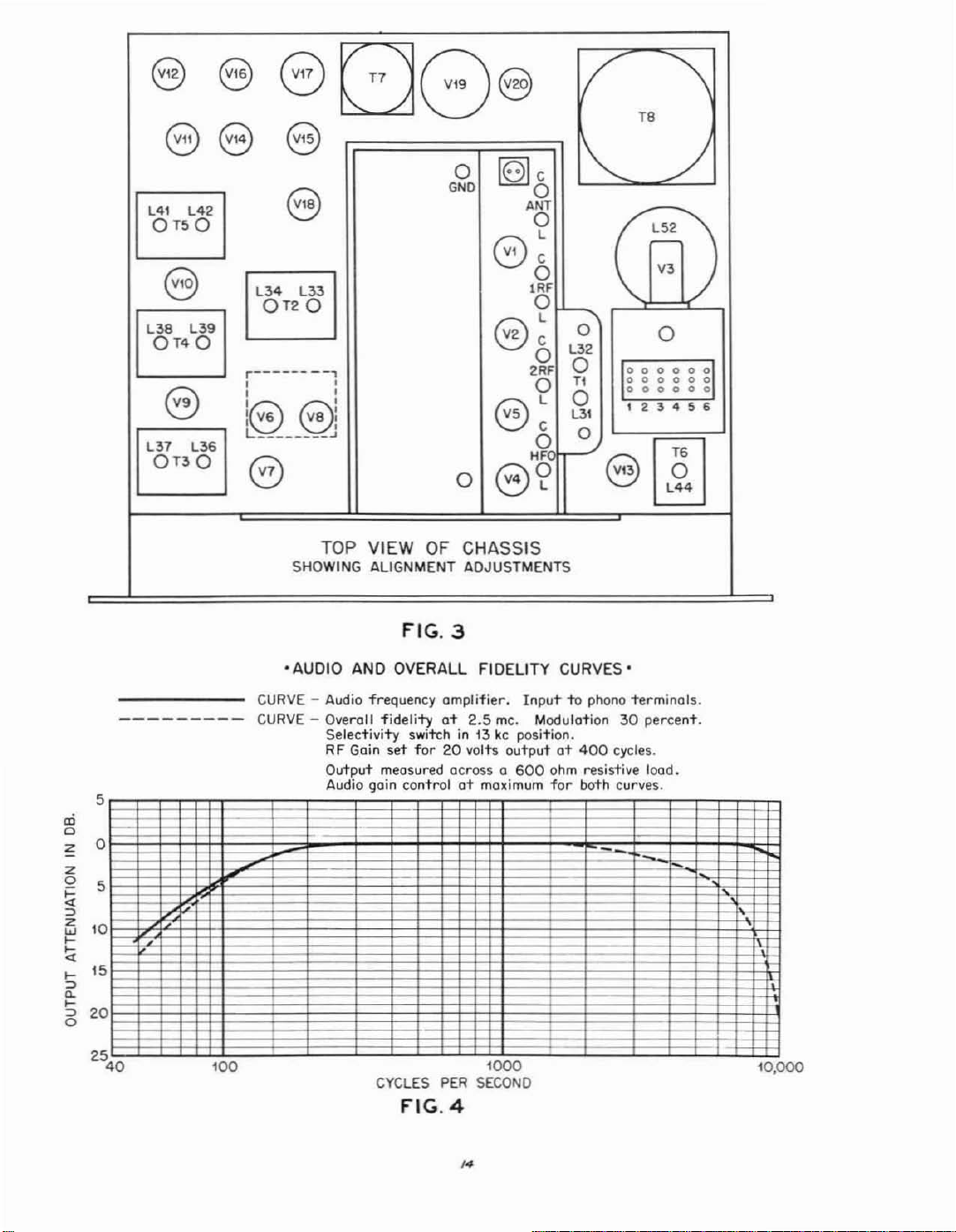
TOP
SHOWING ALIGNMENT ADJUSTMENTS
VIEW
OF
FIG.3
~c
GC
e~
@~
8?
CHASSIS
0
ANT
0
L
0
'RF
0
0
2RF
0
0
HF
1"'-
--."
0
L32
0
Tl
0
L3\
0
e 0
/0
~
V3
0
000000
000000
000
0 0 0
I 2:54 5 6
L44
rn
<Xi
o
z
z
o 5
~
::>
i1i
....
\i
....
::>
a.
....
::>
o
'AUDIO
CURVE
CURVE - Overall
5
AND
OVERALL FIDELITY CURVES'
- Audio frequency amplifier.
Gain
fidelity
set
Selectivity
RF
Output measured across 0
Audio goin controlatmaximum
at
2.5
switchin13kcposition.
for20volts outputat400
me.
Inputtophono 'terminals.
Modulation
600
ohm
for
30
percent.
cycles.
resistive lood.
bath curves.
,-
o
-
~
,
~
0
\
5
2
0
5
100
CYCLES
FIG.4
PER
1000
SECOND
\
10,000
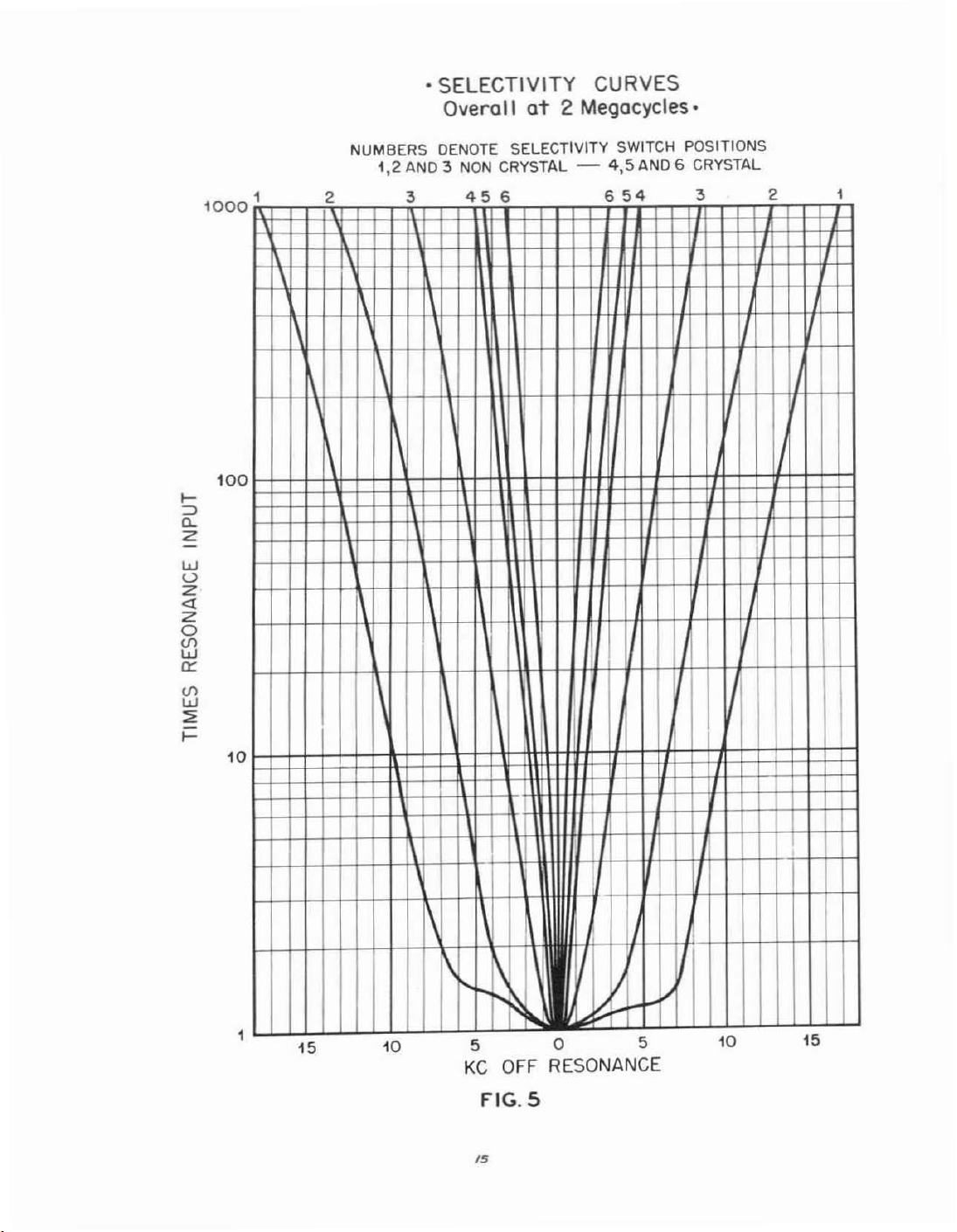
• SELECTIVITY CURVES
Overall
at
2 Megacycles.
>-
:::>
"-
z
w
u
Z
<I
Z
0
(fl
W
0::
(fl
W
:;;
>-
100
10
1a
NUMBERS
1,2
1
0
2 3
DENOTE
AND3NON
456
SELECTIVITY SWITCH POSITIONS
CRYSTAL - 415
AND6CRYSTAL
654
3 2
1
1\
0
i
,
15
10
"'
....
~
505
KC
OFF RESONANCE
FIG.5
/5
l.o::'
I
I
I
!.I
10
15
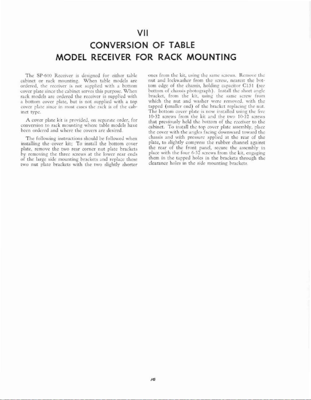
VII
CONVERSION OF
MODEL
Tho.:
SI'·60() RCCC1\"er15UC$l'i!I1Cd
cahinetorrack mounting. \Vhcll table
ordered. Ihe receiverisnot supplied with a bottom
.:o\'cr plate SIlH:C
rack moods arc ord..red
a bottom cover
cover
pl.IlC
met
1}'Po.:
A
cover
conversion to
been ordered and where the covers arc desired.
The
following instructions should be followed
lllslallin~
p1:llc.
rcmO\'e
by
rcmovlIlg
of
the
large side mounting brackcts ;lnd
tWo
nut
the
pl.llC.
.;llllCeInmilst
pl,tlC
kitISpro\'ldcd,
r,lck
the
-co\'er kit:
the
the
plate
buckets
cabinet SCfV':.s this
butisnot supplied
mountinj!
twO
rear corner nut plate brackets
Ihr.:c. screws at
with
RECEIVER
the
rC';":lvcr
elSC!
the
Oil
where
To
install
the
Ihe
two
for
either
modds
purpOSl:.
IS
suppl~cd
WIth
r:u:k
is
of
the
SoCpdr,lt..:
table
the
order, for
models have
bottom co\'cr
lower rear ends
r~place
slIghtly
t<lbl..:
arc
Wh.:n
WIth
:1
top
cab-
when
these
shaner
TABLE
FOR
RACK
oues from
nut
and
tom
bottomofI:has,sls
bracket, from Ihe kil,
whkh
t;tppcd (smaller
The
10-32
that
cabinet.
the cover
chassis
plate, to slightly compress the
the
place With the four 6-:;2 scr.:ws from
theminthe tilpp.:J holes
clearance
lock
ec.Ig,;ofthe chassis. holdmg C,lpaCltur
the
bottom
screws from the kit ,lnd the two 10,32 screws
previollsly held the hottom of the receiver10the
To
anJ
rearofthe
MOUNTING
the
kIt,
USll1~
....
asher from
pholllgraph) Install Ihe
nUl
and
washer
end)ofthe
CU\'U
plateisnow l1lstatled
install the top cover plate assembly, pldee
WIth
the
dn~1cs
with pressure
front
holes
III
the sldc
the $,\m,' 'erews. Remove
the
!crcw, near.:st
U~l1lg
the
...
1m,;
wer..:
rel1l()vec.I,
bracket replal:lI1g Ihl: nut
faclllg:
dl)Wnward tow:trd
appheJ
P,Ut.::!.
lI\
mountll1~
at the rearofthe
rubber
s.::curc.
the
the brackets
the
hrack':IS
the
CIS
short
s..:rew
with
US1l1~
chaonel against
assembly in
kit, eng<tging
through
the
bot-
I
(~"
an!.:!e
from
th.::
the
fiv.-:
the
the
'6
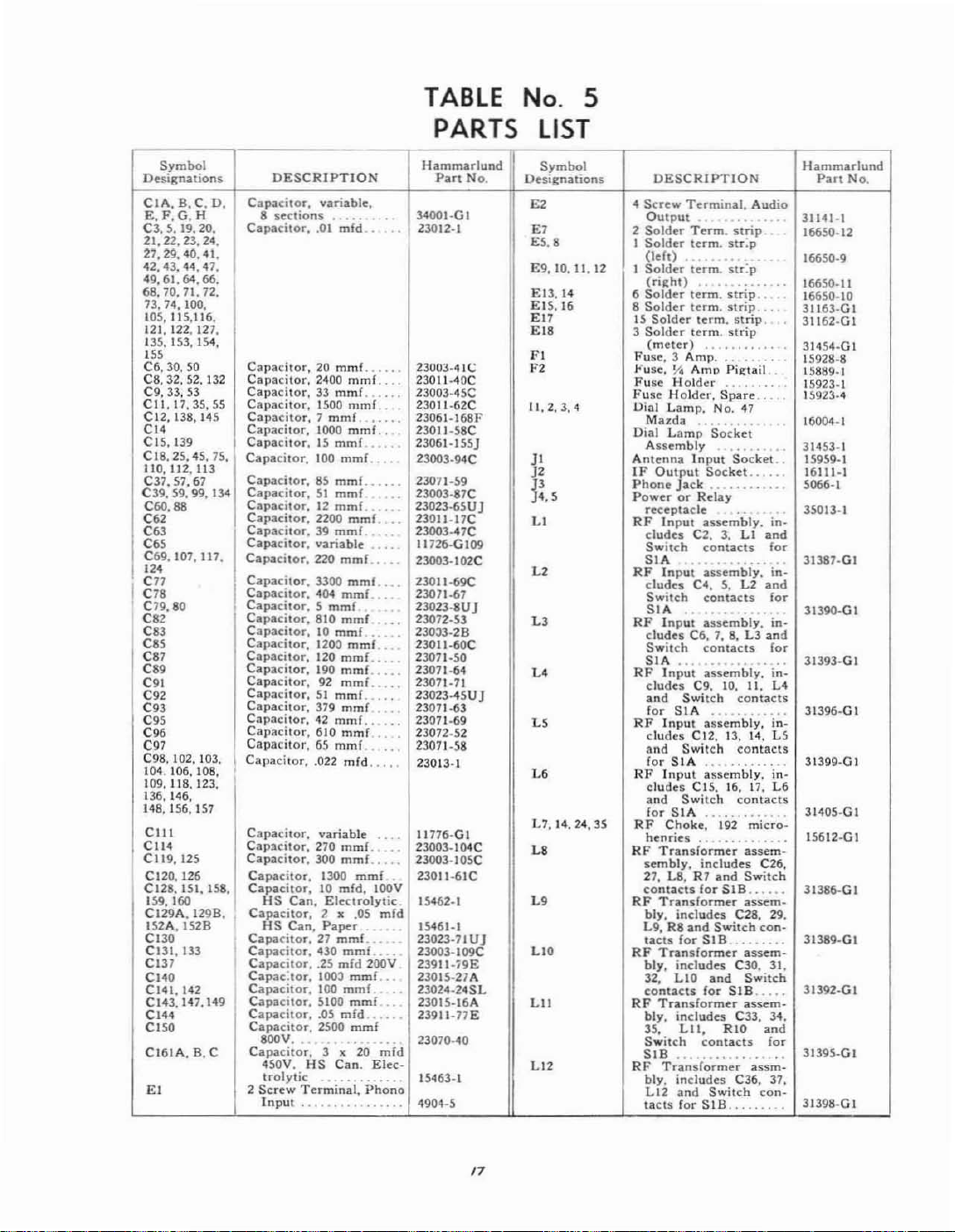
TABLE No. 5
PARTS LIST
Symbol
Designations
CIA.
B,C.
E,F,G.H
C3.$.19.20.
21,22.23.24.
21,29,40.41.
42,43.44,
49,61.
68.10.71.
73.74.
105,115.116.
121. 122,127.
135.153.154,
IS'
C6.
30. 50
C8. 32. 52.
C9.
33,
Cll.17,35.55
C12,138.145
CI<
C15,1J9
CI8.25.45.75.
110. 1I2.
C37.57.67
C39, 59.
C60.88
C62
C63
C"
C69.107.117.
12'
cn
C78
I
C19.80
C82
C83
C"
C87
C89
C91
C92
C93
C"
COO
C97
e98,
102. 103.
104.
106,
109,118.123,
136,146,
148,1.56,157
CIlI
CII4
C1I9,125
C120, 126
C128.
1.51,
159.160
CI29A.I298.
152A,1528
CI30
C131,13]
CI3l
CI40
C141,142
CI43.147.149
CI44
CI50
CI61A,
£1
D. CapOICilor,
'!1.
64. 66.
72.
100.
132
53
113
99.134
108,
ISS.
I
B, C
DESCRIPTION
8
Capacitor,
Capacilor,
Capacitor.
Capacitor,33mmf
Capacitor,
Capacitor,7mmf
Capacitor.
Capacitor,15mmf
Capacitor.
Capacitor.85mmf
Capacitor.51mmf
Capacitor.12mmf
Capacitor,
Capacitor.39mmf
Capacitor,
Cap.acitor.22O
Capacitor.
Capacitor.
Capacitor•.5
Capacitor.
Capacitor.10mmf
Capacitor.
Capacitor.
Capacnor.
Capacitor,92mmf.
Capacitor,51mm£..
Capacitor,
Capacitor.42mmf
Capacitor.
Capacitor,65mmf
Ca,Iacilor..022
Capacitor.
Capacitor.
Capacitor.
Capacitor.
Capacitor.10mfd,
HS
Capacitor.
HS
Caj».citor.27mmf_
Capacitor.
Capacitor•.2.5
CapaC:l0r.
Capacitor,
Capacilor.
Capacitor,
Capacitor.
8OOV.
Capacitor.
4S0V.
trolytic
2
Screw
Input
variable.
sections
.01
mfd 23012_.
20 rnmf.
2400
mmf.
1500
mmf.
1000
mmf.
100
mmf.
2200
mmf.
variable
mmf..
3300
mmf
404
mmf
mmf
810
mmf
1200
mmf..
120
mmL
190
mmf.
379
mmf
610 rnmF
mid
variable
270
mmi.
300
mmf...::
1300
Can,
Electrolytic
2
.0'
•
Can.
Paper
430
rnmf_..
mfd
100J
mmf
100
mmf
5100
mmf
.05
mfd
2500
mmf
..
3
•
HS
Can.
Te~~j~~i:
.........
....
......
.
....
...
..
...
..
..
....
:
~
....
....
...
..
..
..
..
..
..
..
...
..
...
..
"
..
mmf
.
IOOV
mid
..
200V
..
..
..
mid
20
Elec-
Ph~~o
......
Hammarlund
Part
No.
34001-0.
23003-41(,;
23011-40C
23003·45C
2301l·62C
23061.168F
23011·58C
23061.155J
23003·94C
2301\·59
23003·87C
23023·65UJ
23011·17C
23003.47C
11726·GI09
23003·102C
23011-69C
23071_67
23023·8UJ
23072·53
230J3·28
2301I·6OC
23071·50
23071·64
23011·71
23023-45UJ
23071·63
23071_69
23072.52
23071-.58
23013-1
11776·GI
23003.I04C
23003-105C
23011-61C 27, L8,
15462·1
15-'161·1
23023·71UJ
23003·109C
23911·:i9E
23015·21A
23024-24SL
2301.5-16A
23911-77E
23070-40
15463-1
4904·5
Symbol
Designations
£2 4
£7
ES.8
E9,
10.
II,
12
E13.14
E15,16
£17
£18
FI
F2
11.2.3.4
JI
J2
J3
J4.5
LI
L2
L3
L'
U
L'
L7, 14.
24,
35
La
L'
1I0
LII
L12
DESCRIPTION
Screw
Output
2
SoJdn
I
Soldcr
(left)
I
Solder'
(riiht)
6
Solder
8
Solder
15
Solder
3
Solder
(meter)
Fuse,
"'usc,
Fuse
Fuse
Holder,
Uial
Lamp.
Muda
Dial
l.amp
Assembly
AIlIenna
IF
Output
Phone
PowerorRday
receptade
RF
Input
dudes
Switch
SIA
RF
Input
dudes
Switch
SIA
RF
Inp~;
dudcs
Switch
SIA
RF
Input
dudes
'0'
fo,
RF
Input
dudes
'0'
for
RF
Illput
dudes
'0'
for
RF
Choke:'
henries
RF
Transformer
sembly.
contacts
RF
Translormer
bly.
L9.RSandS.....
tacts
RF
Translonner
bly.
32.
contacts
RF
Tran.sformer
bly,
".
Switch
SIB ..
Tr'a'n"s1o'r~~~
RF
bly.
L12
tacts
Terminal.
_
Term.
term.
term.·~tr:p
term.
term.
term.
term.
3 Am'p
!I.i
AmI) Pit/:tail
Holder
...
Spare
No.
Audio
strip
Slr:p
strip
strip
strip
strip
.......
..
-'17
..
..
..
...
..
S~Ck;t
Input
Socket.
Socket..
Jack
..
asse~bly.
C2. 3. L I
contacts
~s~~~biy:
C,.
contaca
a~~~;"biy:
C6,7.S.L3and
contacts
a~~e~bly.
C9,
Switch
SIA
a~~~~bi;:
C12.
Switch
SIA
assembly,
C15.
Switch
SlA
..
includes
R7
for
includes
forSI8
includes
LIO
'0'
for
includes
LII.
contacts
includes
Switch
'0'
for
SIB
,.
10.
13.
16.
i92
......
and
SI8
C2a. 29.
itch
C30. 31.
SIB
C33, 34.
RIO
C36,
...
..
in:
and
fo,
in-
L2
,,'
'0'
·i~.
fo'
i~:
L,
II
.
contacts
'i~:
1<
. U
COntaCIS
...
in.
t7.
L'
contacts
micro-
.
...
assem-
C26,
Switch
...•..
assem·
con-
....
_.
assemSwitch
..•..
assem-
'0'
fo'
.
assm-
37.
con·
....
..
..
Hammarlund
Part
No.
31141_1
16650-12
16650-9
16650-11
16650·\0
JII6J·Ol
31162·Gl
31454-01
15928-8
158119.1
15923-1
15923·-'1
16004·1
31453-1
15959·1
16111-1
5066-1
35013-1
31387-GI
31
39O·G I
31393·GI
31396·GI
31399-GI
31405·GI
15612·GI
31386-GI
31389·GI
31392·GI
31395·GI
31398·GI
17

PARTS
LIST
(Continued)
Symbol
DesIgnations
L13
L15
L16
L11
LI8
L19
L20
L2I
L22
L23
L25
L20
L27
L2S
L29
L30
L<7
L48
L49.
SO
LSI
L52
L53
MI
PI
P2
P3
P,
DESCRIPTION
RF
Transformer
bly,
includes
til
and
tacts
for
Same
as
C46. 47.
Switch
SIC
.. ........
Same:
35
C48, 49. 1.16. RIB
Switch
SIC
Same
as
C~O.
51. 52, 1.17,
and
Switch
for
SIC
Same:
as
C53, 54, 55,
and
Switch
for
SiC
as
Same:
C56. 57.
Switch
SIC
Same:
as
e58.
Switch
SIC
RF
Choke,
RF
Choke.10millihen.
ries
RF
Choke,25millihen-
ries
HI"
Ost,
cludes
L25
and
tacts
for
HF
Osc,
c1udes C81, 82,
and
Switch
for
SID..,.., .
HI"
Osc.
dudes
L27
and
tacts
for
HI"
Osc.
c1udes C8!i. 87, 88. 89,
L28
and
tacts
for
HI"
Osc,
cludes
L29
and
t3ctS
HI"
Osc.
dudes
and
Switch
for
SID
RF
Choke.
ries.
RF
Choke.2ohmsdc..
RF
Choke,
1st
Filter
170
ohms
2nd
Filter
440
ohms
I I"
Output
Tunin~
Power
plug
Antenna
Antenna
nector
Cable
Connector
(for
J2)
C38. 39,
Switch
SIB
L8.
includes
LIS.
R17
contacts
L9.
includes
contacts
L10,
includes
contacts
1.11,
includes
LI8,
contac~s
L12.
includes
L19
contacts
1.13,
includes
59, L20
conlatls
1
~fliil';~~;~
"..,.
assembly,
Ci6,
71, 78,
Switch
SID
.....
assembly,
contactS
assembly,
C83, 84. 85.
Switch
SID
...
assembly,
Switch
SID
...,...
assembly
C90, 91. 92. 93.
Switch
for
SID
assembly.
C94. 95. 96.
contacts
3,8
millihen-
.. .,
...
2.7
ohms
Choke
8.5 H
dc
Choke20Hy,
de
Transrormer
Meter
and
cord
Input
Plug
Adapter
assem-
con·
and
for
and
for
""
Rig
R20
and
lor
and
for
con·
"
L26
con-
con-
con-
in-
L30.
de.
.,
...
Con·
Plug
..
..
in-
in.
in-
in·
in-
.
y,
31404-·GI
31386-GI
31389-GI
31392·GI
31395-GI
.
31398·GI
31404·GI
.
15611-1
31030-2
31031_2
Hammarlund
Part
No.
15617·GI
15618·1
15619-1
31385·GI
31388-GI
31391-GI
31394_GI
31397-GI
31403-GI
1~16-GI
15613-1
31488-1
4903-2
6143_1
16016-1
15987-1
16071_1
Symbol
Dc:siRnalions
Rl.
13.26
R2. 12. 44. 52.
57.82.90.91.
92.70
R3. 14. 39, 48.
53
R4, 6.
16.29,
30.83.102.
R5.15.32
103
10110
R7.8.17.18
R9.19
RIO.
11.20.21.
R22, 23. 64. 65,
R24,25
"
R27
R28
R31.
37,41.
54.58.80
R33
R34. 35. 38. 43,
51.56,62,67.
68.75.76,81.
100
R36.96
R40
R42,
50.
55
R<S
R46.94
R47.66
R59
R60.61
R63
R69.74
R72
R73
Ri8.98
R19
R84
Ras
R86, 89, 95
R87,88
R93
DESCRIPTION
Rui9tor
watt
Resistor
wall
Resistor
watt
Resistor
watt
Resistor
watt
Resistor
wall
Resistor
watt
Res:stor
watt
ReSistor
watt
Resistor
walt
Resistor
watt
Resistor
watt.,
ResiStor
49.
watt..
Resisor
watt.,.,...
Resistor
watt.,
Resistor
watt..
Resinor
wall
Resistor
watt
Resistor.
watt
Resistor,
watt
l<esistor
watt
Resistor
watt..
ResistorImegohm
watt
Resistor
watt.....
Resistor
ohms.
Resis:or
watt
Resistor
watt...
Resistor
watt
Res:stor
watt
Resistor
ohms
Resistor
watts
Resistor
watt
Resistor
watt
Resistor
ohms
SIO
510K
.,
10K
33K
....
1000
510
51
..
24
..
47K
180
150
6800
. ,
2200
1500
lOOK
..
22K
20K
....
240
1100
18K
2200
27K
20K
470K
.....
680
..
variable
.,
2500
82K
120K
includes
..
ohms
ohms
ohms
,.
ohms
ohms
ohms
"hms
22
ohms
ohms
ohms
ohms
ohms
....
. ....
ohms
ohms
ohms
10
ohms
ohms
..
ohms
.,
...."....
variable
ohms
..
56K
ohms
.
ohms
variable
..
ohms
ohms
ohm;'
ohms
ohms
ohms
ohms
ohm
ohms
.
switch
l-S
Y2
~
',;
I/z
.
...
1000
SOOK
SOK
Hammarlund
19317-7681"
19309-27881"
19309-2828
19309_4981"
19309_17081"
\Ii
19309.19381"
19309-18981"
19309-981"
\Ii
19309-898
Y;
19309-3181"
Yi
19309-25981"
Yi
19309-6981"
..
\Ii
19309-5781"
Vi
19309-5381"
Yo
19309-97BF
Yi
19309·1788F
I
19310·179BF
\Ii
19309·IBP
Yi
19309-201BF
Yi
V.
19309-208BF
19309·79BF'
I
19310-5781"
'h
19309_12181"
I/z
19309.83BF
15363-1
Vz
19309·21881"
I
19310.186BF
Vz
19309-113BF
Vz
19309-45BF
.
15342-11
10
19396-1
Y2
19309_287BF
Vz
19309-18181"
15342-21
Part
No.
I"
I~
"
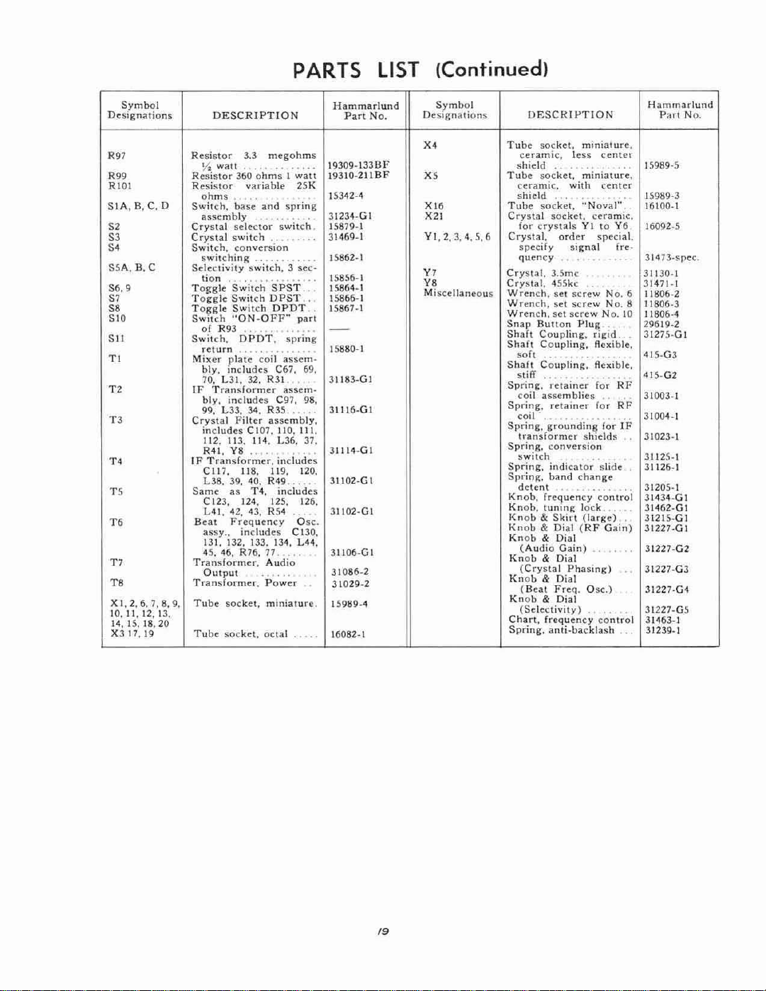
PARTS
LIST (Continued)
Symbol
DC~lgnations
R97
R99
RIOt
SIA.B,C. 0
S2
S3
S'
SSA.
D.C
56.9
S1
S8
SIO
SII
TI
T2
T3
T.
TS
T1
T8
Xl,2,6.7.8.9.
10,
II,
12. 13.
14,15.18.20
Xl17.19
Resistor
Resistor
Resistor
Swill;:".
Crystal
Crystal
Switch,
Selectivity
Toggle
Toggle
To~"lc
SWlIch
Switch,
Mixer
IF
Crystal
IF
Same
Transformer,
Transformer.
Tube
Tube
DESCRIPTION
3.3
Yo:
waH
ohms
assembly
switching
lion
of
R93
return.....
bly.
70. L31. 32. R31
Transformer
bly.
99. L33. 34. R35 .
includes
112. 113,
R41, Y8
Transformer,
CI17,
L38, 39. 40.
C123. 124. 125, 126.
L41.
Beat
assy..includes
13!. 132, 133. 134,
46, R76,
'IS.
Output
soc:ket,
socket,
megohms
360
ohmsIwatt
variable
.
base
and
selector
switch
conversion
switch,
Switch
SPST
Swhch
DPST
Switch
DPDT
"ON-OFF"
..
DPDT,
plate
includes
includes
as
42, 43, R54
Frequency
. .
coil
C67. 69.
C97, 98,
Filter
assembly,
CI07,
110,111.
II~.
U6.
.,.
includes
118. 119. 120,
R49,
T4,
includes
77"
Audio
Power
mmiature.
octal
spring
switch.
3 sec-
,_
.
spring
assem-
...
assem·
..
25K
.
..
..
pan
.....
37.
.
..
...
."
Osc:.
C130,
L44,
Hammarlund
19309-133BF
.
19310·211BF
15342·4
31234·GI
15879·1
31469-1
15852·1
.
15856-1
.
15864-1
15866-1
15867·1
..
15880-1
3118l-GI
l1116-GI
l1114·GI
lll02·GI
,
l1102-GI
l1106-GI
31086-2
31029-2
15989.4
16082-1
Part
No.
Symbol
Designations
X4
XS
XI8
X21
YI.2.J,4,5.6
VI
V8
Miscellaneous
DESCIHI-'TlON
Tube
soc:ket,
ceramic,
shield
Tube
Tube
Crystal
Crystal.
Crystal.
Crystal.
Wrench.
Wrench,
Wrench.
Snap
Shaft
Shaft
Shalt
Spring.
Spring,
Spring,
Spring.
Spring.
Spdn!:".
Knob,
Knob,
Knob&Skin
Knob&Dial
Knob
Knob&Dial
Knob&Dial
Knob
Chart,
Spring,
....
socket,
ceramic.
shield
socket.
socket.
for
c:rystalsVIto
spedfy
quency
l.5mc
455kc .
SCI
set
set
Bulton
Coupling,
Coupling,
soh..
Coupling.
stiff..
l'elainer
coil
assemblies"
retainer
coil'_".
grounding
transformer
com'ersion
switch
indicator
band
detent
frequency
tunin!:
& Dial
(Audio
(Crystal
(Beat
Freq.
& Dial
(Selectivity).
frequency
anti-backlash
miniature,
less
center
miniature,
with
center
.
..
"Noval"
c:eramic.
order
special.
signal
...
screw
No.6
screw
No.8
screw
No.
Plug
rigId
Rexible,
.,..
R~~ible.
.
...
for
lor
..
for
shields
...
slide
change
.,
control
lock
(large)
(RF
Gain)
Gain)
Phasing)
Osc.)
..
control
Y6
fre.
.
,
10
RF
RF
IF
".
..
.
'
.
,
,
Hammarlund
Part
No,
15989-5
15989-J
16100-1
16092-5
31473-spec.
ll130-l
ll~71-1
11806-2
11806-l
11806-4
29619·2
l1275·GI
415·G3
41$·G2
liOOl-1
310G4-1
JI023·1
31125_1
l1126_1
l120S-1
31434·GI
l1<462·GI
l1215-GI
J1227-GI
31227·G2
l1227·GJ
l1U7·G1
l1227-G5
l1463-1
l12l9-1
/9
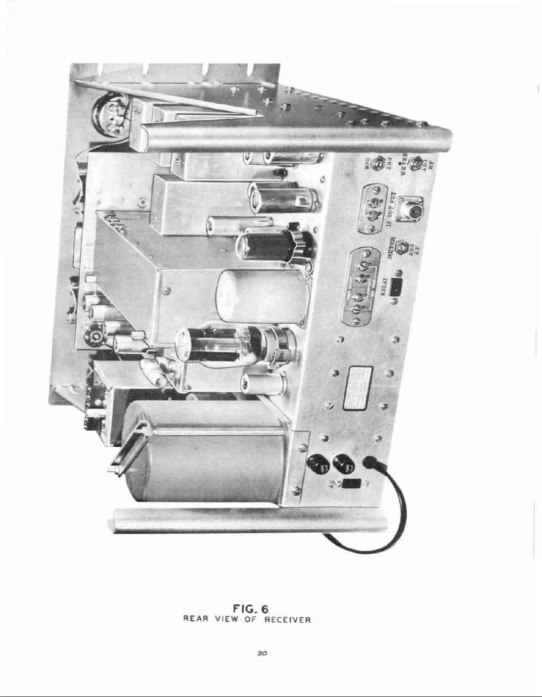
REAR
VIEW
FIG.6
OF
RECEIVER
20

TOP
VIEW
21
FIG. 7
OF
RECEIVER

TOP
CAPACITOR
VIEW
FIG.8
OF
SHIELD
RECEIVER
REMOVED
22

...
u<
e.::=f,j--R"
.-"1---
ROO
gS\
'"
c,'"
,.
"
",
Cl"9
"
e,
C
...
FlIOI
'"
."
Re,
.,.
C,
m
;C147
-::::~~~ll
~n
:::"$-t!==:R"
t
o·
-<
R102
R"
C\4$
RIOO
.,.
BOTTOM
VIEW
FIG.9
OF"
23
RECEIVER
SP-600-JX

BOTTOM
TUNING
UNIT
FIG.l0
VIEW
SHIELD
OF
RECEIVER
REMOVED

FREQ.
CONTROL
lSI
RF
VI
68A6
2ND
V2
68A6
RF
,
V7
'"
GSA
JI
,
_
®-
;;
•
'-
,
CO,
r1'
C1!~
~
L_C'7"C/+-,-c--'/~CIH
l----*-h
~
C7'
5
'"
m
,,;~
J_../
®
•
f--11rt
-,
,
,
I
I
i
i
I
,
I
,
,
I
I
,
I
I
'"
•
•
'25
rf
•
R~~
llC41
TIl
t '
CIC~
__L__
...L...____
K';="
"
CIO
L
__
TUNING I
~+
-
I"i~;r.
,
uF
".
s"
CO,
"o',.JL-,-'-C/j'"
.£
J.
C4~
,
RI~
I
t
N
"
•
,.------
I
I
I
I
I
I
I
I
'ntl2q:~f"sa::JN--
1"·~<IM,
"
I
I SINGLE CO!'iV(IISlON
I
.S<l·T4
I
CIO!
,'-'
tile
(
...
•..
-_.
---
...
f
:!tcr-,---=-,------,--,
~
ro
~
.1~~"
I·
I.
,.
,.
I
,
I
••
C66
t
,
.------iIHii
~
us
, C81
L30
'-----.,jIH"!!:---'"1.1--
,---0-,
1-
..,I
~
Tf
C95
*
~
)'1
~
I I
I I
I I
I I
I I
I I
I
1/
/rf
I I
I I
I ,
: I
w
ffi
""
I I
~
I,)
•
t
s.
n
RELAY
n
I
I
.
/
/
/
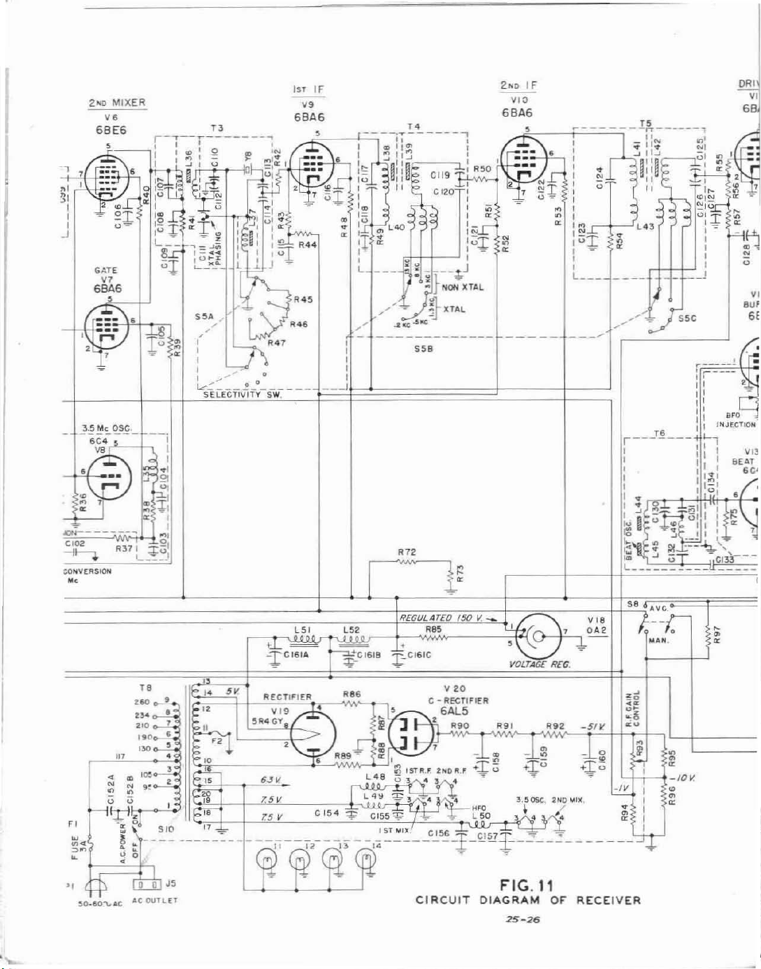
2Htl
MIXER
GATE
GBAG
"
,
',nv
'J:
~.~
~
GO
ss.
,
,
:'
:
.-7
1..,--
.....
__
SELECTIVITY
1ST
6BA6
'"
~R"1
o~
0_°_
SW.
2>ll>
IF
"
IF
YOO
6BA6
CONV£IlSION
.<
"
<,
.12
REGULATED
~CJ6IC
CI
'"
RCUIT
150
v:
__
DIAGRAM
25-26
or
S8
.~
_0
Cc
o'
.~
co
RECEIVER
Ave
I-':~
"
f
•
,
•
<
,
I
•
,
•
<
I
I
I
,
•
<
10
V.

--
--,
,
,
,
--=c'
119
:;:1
R50
,
,
,.
'N
'",±
:OI
J
,
---1,.J
NON
XTAL
-
XTAL
'EO
150
v._
~'
V
'0
,RECTIfiER
6ALS
2ND
"0
6BA6
,
,
1-=,.
2
:-6r
~
=
;;
N
•
•
/'
'
Lt.
m
~V~-
VDLTAGe
IF
0"'-
'-
c
,
,
,
,
,
,
,
,
,
•
,
•
•
:~1
0
1
,
,
,
L
___
\1 OA 2
RCG.
DRIVER
VII
6BA6
"
i'-~;----~
VI8
"I::in:
•
0
"
=
II
II
~
:
'"
•
•
•
----
S8
AV~r:--
,
lolA"'.
:~N:~
l
-
0
•
•
•
10
•
•
•
~
--'
V.
1 l
I...
1lI1!';!
U1.I
1_
I I
I
,
I
~
s:Jl
~~
'+-=:_{,r
1
a:"'-
C;
•
.,
N
0
VI2
BUffER
6BA6
,
C!.E...l1
-+
•
,
•
•
0
0
,
•
•
PHONES
k©1
'l.F..A.F,
<l:
~T
U-
OFF
' IolDD-CW
r
§,
L.-
J'
METER
"'
LEVEL
:::~
~:f:
'"
"
'"
'"
-~
CI38
CI39
V,.
2/lD
DETaAve.
GAL5
,.,~*"
~
~
;;;
R67
~C!41
:
$C142
VI5
LIMITER
OUTPUT
METER.
6ALS
6-
•
,v.
IolnEIl
'"
Ae
~r-r--'=
,
"
I
,
~
I
•
I
I
,
,
I
I
•
I
J
-
:
~
~
IF
57
I
T7
J.-
1;
ie
,
' '
,
•
,
I
r,
,
,
~
'"
R.f.
"
"
,
"
A.F.
~
I
•
•
•
•
•
~
''0
OUTPUT
LEVEL
,w,
12AU7
1ST
"
,
0'
~
VI'
OUTPUT
GVGGT
'r-
./
r--.
I
••
,
.-
RIO!
AUDIO
VI6B
I
-
t
:UlT
FIG.
DIAGRAM
25-25
'1
OF
RECEIVER
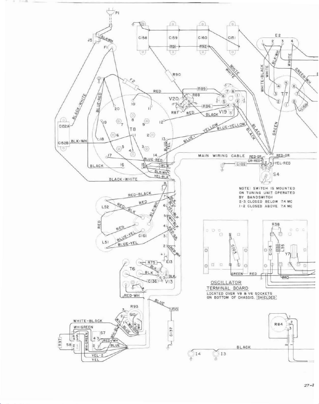
BLACK
B A
-
K-WHI
o
'@
LU
,.
-RED
,
MAIN WIRING CABLE
,
...,....-...;CIQ2:
l I
iGR~C~'~£O~-
NOTE. SWITCH
ON
TUNING
BY
BANDswrTCH
2-3
CLOSED
'-2
CLOSED
,F.i'~.J"-'-GR
2:3
'f
S
h
'
UNI~S
MOUNTED
OPERATED
8ELOW
ABOVE74Me
14
Me
WHITE-BlA
WH-GREEN
co,
K
,
-,
.:-I~4;----~~:~I~3~_·elJ.!A"C",,--_----~·i'l~
'eo
,
"
-,[---
"
27-'
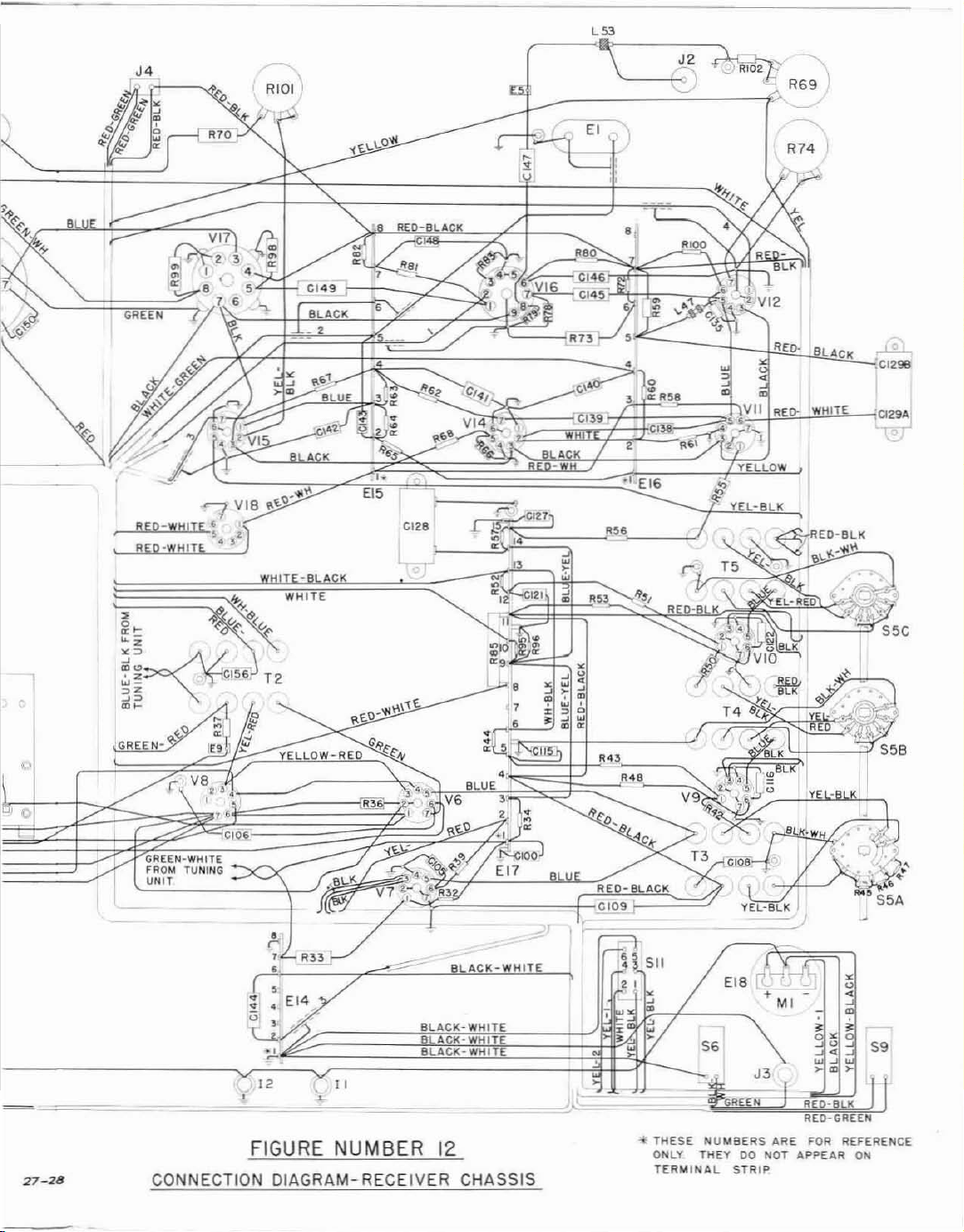
EI C
!:
"
"
>
O~
WHlTE-Q,
":"'~
'0
ACK
WHIT'
~
00
;~vi56'
'z
~i
i6~
N-
"
,
...
" .
II:
.i:f
IE91
_
,.
CI06
T2
2
•
•
•
59
•
27-28
FIGURE
j;CC!'0,!!N~N!!:E~CC!T~I02!N~D~1
NUMBER
E,(C;
M- R
A",G",R.:.:A~_
12
CHASSIS
EEJlI
Vo'EE,!R,--,,-==_
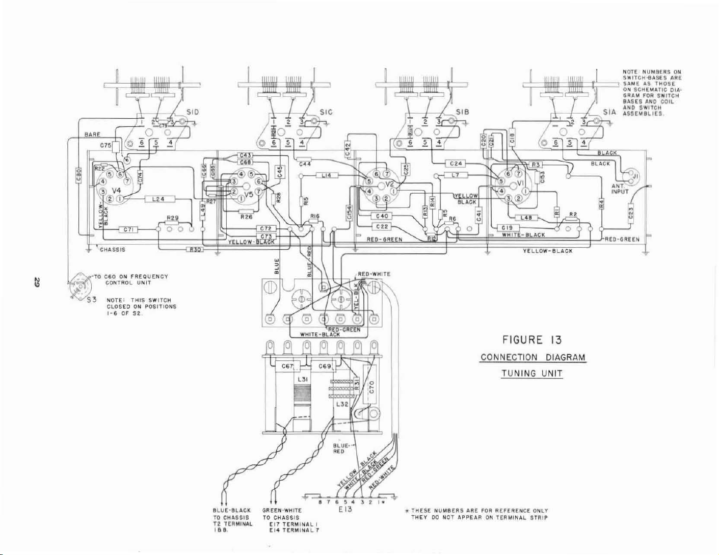
"OTt
III
'II'
~
~c!:
1:::\.
F
,
.
HUMBERS
~:~T(G~·:·:~~s1RE
ON
SCI1[MATIC
::::/2:0
AND SWITCH
ASS[IllILlU
ON
01,1,-
S~~i~H
"
~
~
GIiASSIS
TO
CiDONFREOllEtlCY
:ot
'S3
,
CONTROL UNIT
,..OTE:
THIS
CLOSED
ON
1-6OF52
L-:a-:-4
000
SWITCH
POSITIONS
'-24
SLACK
•
U,
REO-GREEH
Ili
--I,":
:IJ(j)
~V~I
'4f"-'
~
>l@
TO
Y[LlOW-BlACIl
FIGURE
13
BlACl\
~
ANT-:::Q..INPUT
"
o
lui
RED-GUEN
CONNECTION DIAGRAM
TUNING UNIT
8lUf:-lllAClot
TO
CI1ASSIS
12. TERMINAL
".
GREEN'WHITE
TO
CHASSIS
[11
T£Fl)r,IIIUll
£14
TERIIIINH
,
THESE
NUMBERS
TtlEYDO,..OT
T
"IE
FOR
ilPPEUIONTERMINAL
REHII[NCE
a'lLV
STRIP
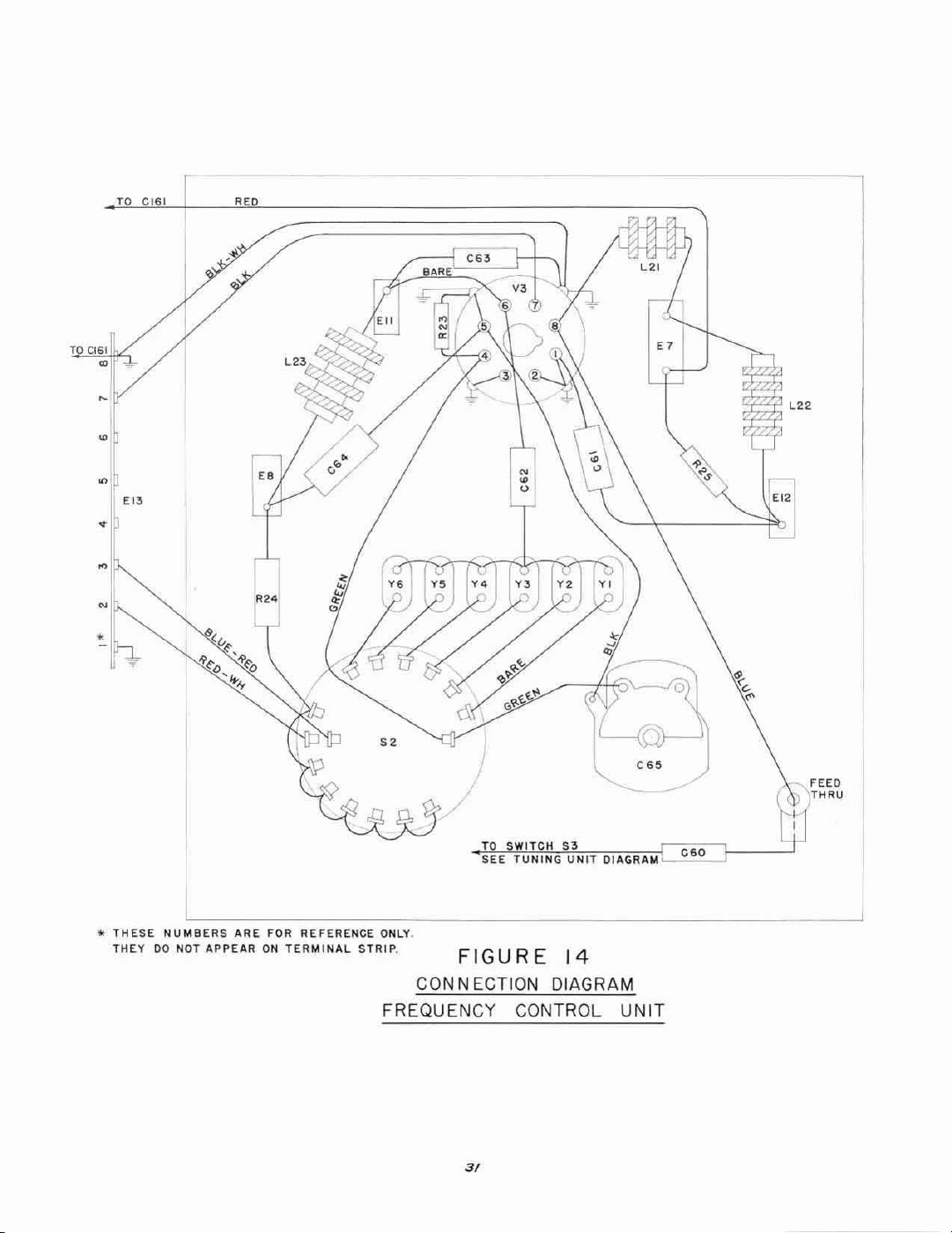
TO
CIGl
,
CIG!
RE
"j
,
•
0
I
'"
•
EB
•
N
~
'"'
THESE
THEY00NOT APPEARONTERMINAL
NUMBERS
"
ARE
FOR REFERENCE ONLY.
TO
SWITCH
SEE
TUNING
STRIP,
FIGURE
CON NECTION DIAGRAM
FREQUENCY CONTROL
S3
UNIT
/4
C65
Ol06.GR06.M
UNIT
C60
3/

Notes

1ST
RF
"
6BA6
2ND
6BA6
"
RF
2,,0
'"
OET6AVe
GAL5
'"
LIMITER a
QUTPUl
METER
GALS
, '
.
25-26
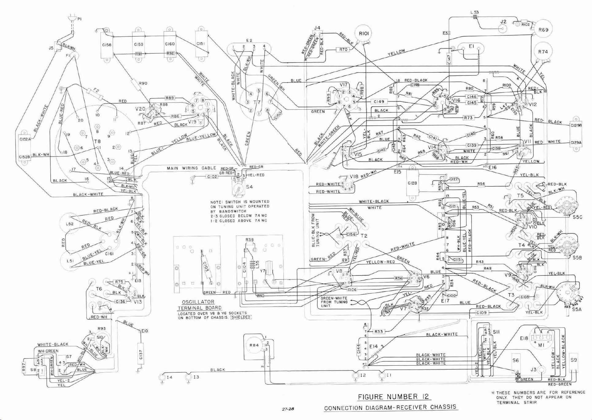
L5>
01
9
WIRING
0
[51
..
.It
~)o
+,.oJ'
f'
e ,
CABLE
C02
NOTE;
ON
ElY
2-3
1- 2 CLOSED
"
I 2
\
< •
u~
<-
"'
••
~
•
~
,
,
•
$W1TCH1$MOUNTED
TUNING
UNIT
BANOSWITCH
CLOSED
ElELOW
ABOVE
,
,')
OPERATED
1.'1lo1C
7.4
Me
WHITE-BLACK
WHITE
REO-BlA
r
_~
::>
,
ft::;
U
•
K
"
"
,I
"
~,
R90
'~
r-
__
C"C':.:IN
~
B A K
-WHIT
L52
'i!fa.
\
__
~-_~~h'i=-
EI
c
II
"
'
"
J2~
__
--jO:69
',11
YEL W
~
YE
,SlK
\
WHITE-BLACK
(~
,
2
• I
<
u
<
$9
FOR REFERENCE
ON
..
I
RB4
'/2
,
BLACK-WHITE
B
ACK-WHlT
BLACK
l'
.-
~==
CONNECTION DIAGRAM- RECEIVER CHASSIS
• I
~"
'C,),12
FIGURE
~
11
NUMBER
8LACK-WHI
12
E
THESE
ONLY
TERMINAL
EI8
$~l
NUMBERS
THEYDONOT APPEAR
ARE
STRIP.
 Loading...