

Page 1
GENERAL
PURPOSE
COMMUNICATIONS
MODEL
INSTRUCTIONS
SP-600-JX
RECEIVER
460
West
THE
Manufactured
HAMMARLUND
by
MFG.
34th St. New York
P,iftted
in
U.S.A.
CO.
1,
INC.
New York, U.S.A.
Page 2
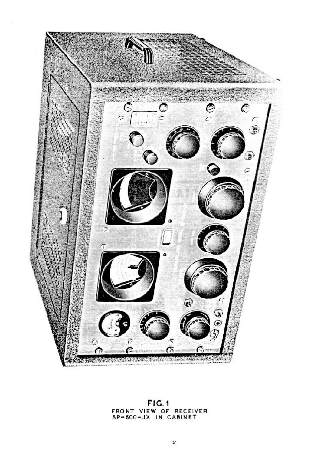
r
F"RONT
SP-600-JX
F'IG.l
VIEW
or
IN
RECEIVER
CABIIHT
Page 3
TABLE
OF
CONTENTS
Titk
Technical
I General Description
II
III
IV
V
VI
VII
Table
Table
Table
Table
Table
Summary
.....................•....•....•..•.
,...............................................................
Circuit
Installation
Description _. . •. . . • . . . .•.. . . . . . . . . . . . . . . . . . . . .•...•. • . . .
..............................•.....•...•.•....•...•......•...•....•.....•...
Operation and Description of Controls .
Maintenance
Alignment
ConversionofTable
I-Tube
2-Tube
3-RF
4-Approx.
5-Parts
.............................................•........•......•.•.............
Mode! Receiver
Socket Voltages
Socket Terminal
and
HF
Oscillator Alignment Frequencies. . . . . . . . . . . . . . . . . . . . . . . . . . • . • . . . . . . . . . . • . .
Signal InputsatIF
List
...........................................•........•.....................
.....................................•....•...
Resistances.~
, . • . . . . . . •. . . . . . . . . . • . . . • . . . . . . . . . . . . . .
. .
for
Rack
Mounting,
.........................•...........................
and
AF
Stages.............................................
.•.
. . . . . . . ..•. . . . . . 6
, .
, .
..
Page
-+
3
8
8
9
l1
l6
lO
II
13
13
l7
figure
Figure 1
Figure l
Figure 4
Figure 5
Figurc
Figure
Figure 8
Figure 9
Figure 10
Fie-ure
Figure
Figure
It
12
13
ILLUSTRATIONS
Front
View
of Receiver SP·600·JX,incabinet
Block Diagram
LocationofTubes
Audio
and
Selectivity Curves
Rear
6
7
ViewofReceiver. . .. . . . . . •. . . . . . . . . . . •. . . . . . • . •. . . . . . • . •. . . . . . . .• . •. . . . . . . . . .
Top
ViewofReceiver..................................
Top
ViewofReceiver-Ca.pacitor
Bottom
Bottom
Circuit DiagramofReceiver. . . . . . . . . . . . . . . . . . . . . . . . . . . . . . . •. . . . • . . . . . . . . • . . . .
Connection
Connection
ViewofReceiver
ViewofReceiver-Tuning
........................................•...•............••..........
and
Adjustments........
Overall Fidelity
........................................•.•....•.•.•..............
Diagram-Receiver
Diagram-Tuning
Curves.....................................................
Shield
SP·6(X)·JX..................................................
Unit
Chassis
Unit
.........•...•........•....•........•............
.......................•...•....•..........
•...•...............•...•....
Removed.
Shield
. . . . . . . . .... . . . .... . . . .•...
Removed.................................
..
. . . . . . . . . . .
•..
. . . . .
2
7
l-i-
14
15
20
21
22
23
2-i25
17
.
29
Figure
Connection
14
Diagram-Frequency
Control
Unit...........................................
3
3L
Page 4
GENERAL
PURPOSE
COMMUNICATIONS
RECEIVER
MODEL
TECHNICAL SUMMARY
Electrical Charaderistics
Frequency Range--total 6 bands
Band 1
B.nd2.............................•...................•....•.•..............
Band3•........•.....•..•..•..•.••.....•..•......•...•....•........•....•....
Band
Band 5
Band 6
Maximum Undistorted
Output
Phone jack-winding; delivers
600
.....................................•................•.....••.••..•...
.oj.
•••••••••••••••••••••••••••••••••••••••••••••••••••••••••••••••••••••••
...•....................•.........•.....•...•....•..•.•......•......•..
................................................................•......
Output-approximate-2.5
Impedance-600
ohm
power loadisadjustedto500 milliwatts.
ohms-bOlla-need
Power Supply Requirements
Line
Rating..........................
Power
Consumption..................................
......•....•.•.•....•....•...•....•..................
watts.
split windings.
15
milliwattstoan 8000 ohm resistive load, when
9$, 105, 117. 130,
SP-600-JX
190,210.234
130 watts, 1.25 amps.at117 voltr-maximum.
.54to'4.0
.5"to1.35
1.35to3."5
3."5 to 7."0
7."0 to 1".8
14.80to29.7
29.70to5".0
the
audio outputtothe
and 260 volt taps, 50-60 cycles.
me
me
me
me
me
me
me
Tube
Complement-total
RF,
IF
and
BFa
·Amplificrll _
HF, 2nd
Crystal Controlled
Mixers.
Detector,
AF
Power
Rectifier. ••. . . •. . . . . . . . . . . . . . . . • . . • . . . . .• . . . . . . . . . . . •. . . . . . . . . • . ••. . . . • . • . . . . . . ..•1- 5R"GY
Voltage Regulator
Conversion and
HF
Oscillator. . . . . . . . . . . . . . . . . . . • . .. . . . . . . . . .. . . •. . . . •. . . . . . •. . ...1- 6AC7
. . . . . . . . . . . . . . . . . . . . . . .. . . . . . . . . . . . . . . . . . . . . . . . . . . . . . . . . . • . . . . . . . . . . . . . . .
"C"
Bias Rectifier and Noise LimiterfTMeter
Amplifier and
Output
IF
Output
.................................•......•.....•.........•......•.....
.............•.............................•.....................
20
.....•...................................
BFa
Oscillators
....................................•....•..............
........................................•.....
Rectifier
...................•.....
7 - 6BA6
3-
..
2 - 6BE6
3- 6ALS
1- 12AU7
1-6V6GT
1-
Mechanical Specifications
Rack
Model-Dimensions;
surface.
Table
Weight66Ibs_
Model-Dimensions;
Performance Data- (approximate values-taken on a sample receiver)
Sensitivity is
of10to
Image rejection ratios are
TheIFrejection ratioat600 kcis2700 to 1
The
AVC
200,000 microvolts.
2.3
microvolts.orbetter, throughout
l.
action will maintain the
19
inches wide,
2Iti
inches wide.
better
than 80 db throughout the frequency range.
output
1O~
inches high and
12~
inches high and
the
entire frequency
constant within
12
16~
nnge,
db when
inchell deep from
17;4
inches deep.
for a signaltonoise power
the
input is increased from 2
Weight
nck
6C4
oAz
mounting
87}1lbs.
ntio
to
Page 5
GENERAL
PURPOSE
COMMUNICATIONS
GENERAL DESCRIPTION
The
SP-6Q(}]X
R~cciW'r
suffix in
is made in ilc:urmnce with
the exceptionofthe
tors
"..lues
ferred
with
this
where
spectal design considerations require special
cnd
~lue
permit their use.
equalorsuperior to
The
receiver is supplied in either a well ventilated
sted.
table model cabinet finished in dark greytocom-
plement
the
in a standard 19 inch relay rack.
The
self contained power supplyisdesigned for
operation from a single phase. 50to60 cycle alternating
current
primary is provided with tilps coveringa.line voltage
range
from 90to270
is
t
10
watts..
The
receiver is suitlble for either headphone or loud
spulc.e:r rttepcion
graph
or
AM
The
standard
OVtt
a frequency range from 0.S4 to 54.0
in six bands.
control knob,
frequency band
a small front pane! window indicates
hnd
in U$C. This control
indicator with the proper dial scale.
In
addition to
has an arbitrary scale which in conjunction with the
b;md spread dial provides continuous band spread
scales over each frequency
tate logging and tesetability.
The
single tuning control is large andofspecial deaigntopermit m;lximum
ceptional operating ease.Itcontrols both
and
band
spread dials. An anti-backlash
provides extremely close calibration accuracy
pletely accurate resetability. A tuning
pll-'itive locking a.ction without alfecting the frequency
setting.
The
tuning ratio from the tuning control to
main dial is50to 1 and the n.tio from the
d~1
to the main
An
ingeniously designed rotary turretisemployed
to change bands
the
RF
amplifier. Mixer and First Heterodyne
isil20 tube Radio Communications
self
contained
modd
number &noUS
useofa few capacitOR
tolerances not included in
lists
or
where space limitatiOn! do not
The
special componentssoused are
the
powu
supply.
that
JAN
speci6carions. with
the
JAN
componentsinquality.
this
The
rtteiver
,lind
JAN
resis-
lighter grey front panel or for mounting
power source.
of
AM
MCW
The
on
telegraph signals.
modd
large
the front panel, selects
and
a hand indicator visible through
the
frequency scalu, the main dial
did
is 6
andtoplace
The
pov.·u tran.s(ormer
","Olts.
The
fIO'NU
radio telr:phone,
CQnNmprion
CW
provides continuous CQvcnge
megacyd~
QSI1y
operated
also
aligns the dial frequency
band
for extremely accu-
tr.lV1!:l'Se
to
apeed
1.
the
band
change
the
desired
the
frcqucm;:y
ill
weU:uex-
the
gen
and
lock
provides
band
sprud
coil assemblies
main
tnin
com'
tde'
Qscil-
]X
pre-
the
o(
RECEIVER
lator
sta.ges
tionsofthe four gang tuning capacitor and
spective
high signal to
Two
arr:
provided on ..II bands.
vemon, used on frequenciesupto
cludes a mixer, heterodyne o.sciHator, four stages
IF
amplification, detector and
limiter and meter rectifier. heat frequency oscillator,
beat frequency buffer amplifier, IF output,
ner
and
conversion, employed
cycles, includes a second mixer and a second heterodyne crystal controlled OKilIator.
system includes
a voltage rtgub.ror.
The
nel
crytta.l
chO!Cn
controls permit the
ity
continuously
selened fixed frequency
bed.
channel
dioaltothe
qumcy
trol.
No
desirable, when llwitching from
tion for
not
aupplied with
chased
MFG.
it
istofunction.
The
relative strengthofthe
microvolt. when operated on
Rain
controlatmaximum. 1\ rear control is provided
for adjustment~tthe
RF
signal
panel meter
cat£l1
the
wan
..
the0db
The
constants for
quency oscillatot employs a
cuit which gives a high order of frequency stability
and minimizes oscillator harmonics.
quencY oscillator voltageisintroduced into
teetQr throukh a bulfcr ampliner which eliminates
OKillator lock-in.
tune $ignais sharply to
diucrly
adjacent
to
their
respecti
....
e
.sec-
their
tuba.
stag..."
output
frequency control
within
This
noise.
assuIe5
ratio.
maximum sensitivity
of tuned r.\din frequency amplification
The
circuit (or single con-
7.4
megacycles., in-
AVe
tl:ctifier, noise
AF
power
~
controlled
the n.ngeofthe
stage.
for
The
circuit
for
frequencies above 7.4 mega-
The
power supply
B power rectifier, C bias rectifier and
Wlit
Open.tK)fl
provides
on any six frequencir:s
receiver.
(or
bed
front
ampli-
double.
chM!-
panel
wectionofthe normal high stabil-
vuiable
opention
signd
frequl:IlCY,
desired and
retWlingofthe
the
same signal frequency.
on
special
CO.
specifying
two
scale tuning meter normally indicates the
input
of
10
SWItch
audio
output
nming or eitherofthe
signak
it
tune
widt
the
recaver,
order
the
rectived signal in
plus20db
micro'l/Olu.
For crystal controlled
is only
5wilCb
necesstry
to the cry5Ul
to
.5rt
fn·
the delta frequency con-
mJ.in
tuning is nr:cessary or
VFQ
to
crystal open.-
Theae
crystals are
bur
from
HAMMARLUND
aMuld
be
pur'
signal frequency for which
db
from 1
Ave
and with the
scale
mding
On
depressionofthe
with
the lower scaleofthe metee indi-
pawn
level indbfrom 6 mllli-
A rear control is provided (oe adjustment of
reading.
Ave
drcuir
ON
is provided with $Cpan.te rime
and
MeW
operation.
high
capacity Colpitts cir-
The
The
beat
fo::'
beat fre-
the
This
feature makes it possible to
:ero
beat and
~mits
the
re-
of
six
the
RF
an
tk-
in-
at
5
Page 6
c:hwonofthe
Iator injection
panel control nrielll
to plusorminw
The
noise limiter
ference. from ignition systems
type
noi.sc.
the
limiter.
The
antenm
a balanced
100 ohms_
conventional single
The
audio
lmdorline and is provided
windiog
power
phone circuit
vides
the
trolofsensitivityinthe
outputisapproximately
aignds
600
An
RF gain control is provided
rear
c:ontrol
to
suit operating conditions. A froot
the
a.udio
J :Ke.
circuit
The
limiter switch permits optional
input
circuitisdesigned
line.
The
input
The
nceiver
output
for
bclanced
....
hen
attenuated approximateh'
ohm
power output.
may
wire
antenna_
circuitisdesigned for a
10.1I.J
referredtoan 8000
presenceofstrong signals and
for
adjuacing
beat
effectively limits
Of'
other.sourasofpulse
impecance is nominally
also
the
beat
oacil-
frequency from 0
the
intu-
UK
for
use with
be
operated
with
of
operatesoneither
The
but
leavelll
tion between transmission periods. A
provides
Radiation is negligible and oomplics with
mttIts
install.ttions.
Frequmcy
nnga
a
quency depending
very unusual
600
with
a four terminal split
opt:r",tioll. UnJill.torted
'2.S
watu.
for
ohm
tS
the
manual con-
The
load
db below
ohm
head
pr0-
tuned
_;lily.
The
crysta(
ra.nging
crystal. niter embodies
have proved10effective
Super
mechanical design.
II
CIRCUIT DESCRIPTION
MANUAL
send
nceive
the
for
the
for
shipboard operation and for mu[ti-ccceivn:
drift
between
degru
HP
o.sciUa.tors
selectivity control provides th.r« degrees
and
three
ftom
shup
Pro
Receivers, incorporated in
switch desensiti:es
power
ontoprovide for
connectionofan
Uter a
.001 percent
011
fu
of
frequency stability
and
degrees
(.'2kc) to broad (13.:KC).
the
or
Aye.
the
in~nt
reu
external rd;ay.
l.S
minute warlnupperiod,
and
.01 pc.rcentoffre-
frequency wed.
for
closdy
()f
same circuit features
and
approaches crystal
nCJn-crystal selectivity
desira.bleinHammarlund
an
nceiver
Kcepta.de
require'
Thisisa
wriilblc
improved
recep-
of
The
that
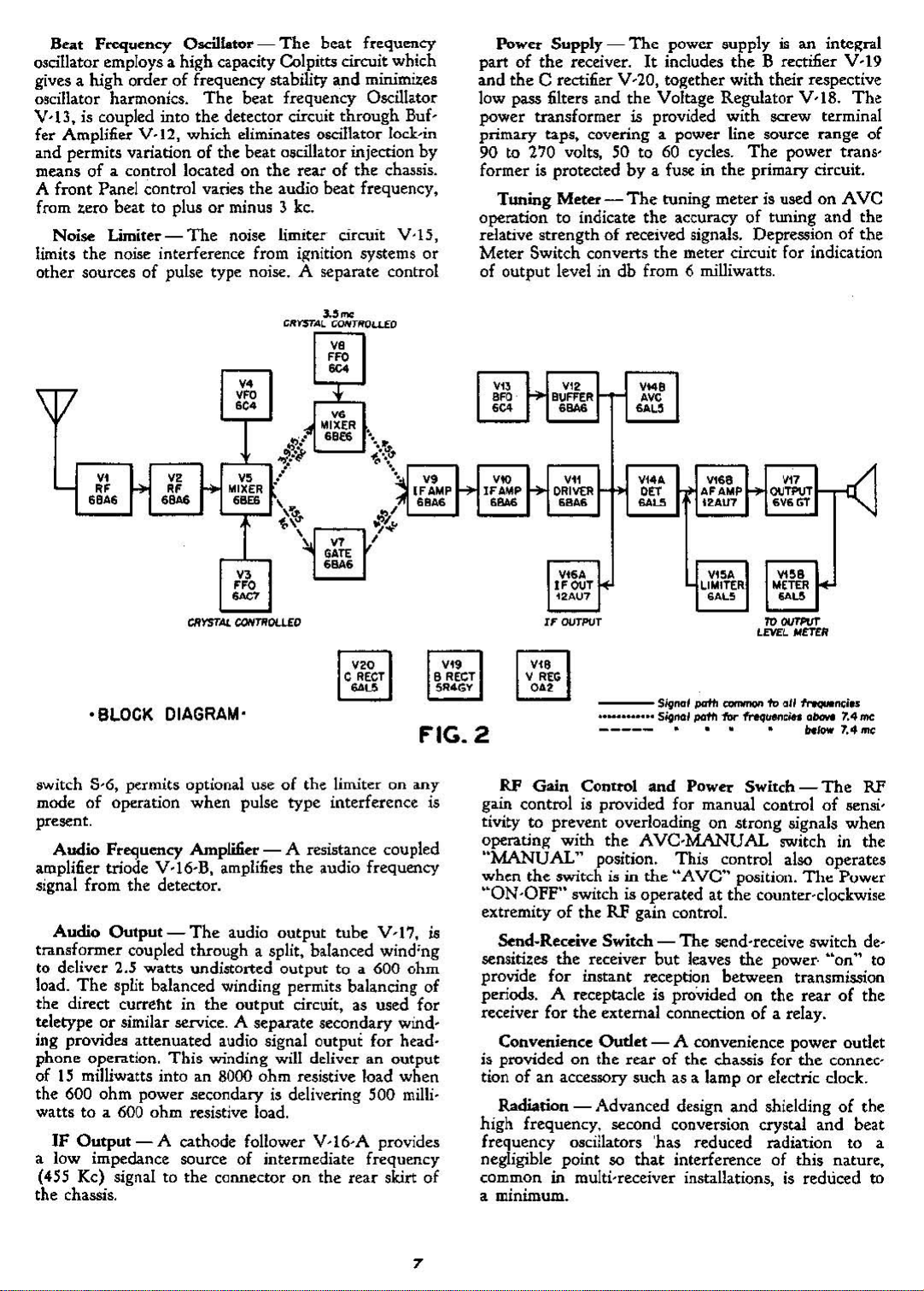
Gmoual-
Figure
more
dearly
the
variou.a circuit sttt:iotu.
ou.s
tubesisshowninFigure J.
cmvcnion,
l"CII1aias
First:
Mixer
stagcaofIF
Detector
Beat
F.requency
amplifier
Y-17
and
Power
age
frequencies above
Second
the
Rectifitt
Regulator
In
the
Gate
Input Coupling-
to
provide
miaaion line. A balanced doubletorstraight
tenna
maybe
RF
AmpIi£e.r
turret
is employed
cciI.
&MCmblic.aofthe
V·ji
and
rectly adjacent
gang
tuning
a..ssutt5
nbo.
rani
The
rotary
The
circutt
II.
A bloc:k diagram, Figure 2, is provided
!how
the
uaed
for
of
two
ata~e:s
V-S, Fira:
amplification V-7.
and
Ave
ltttiiiu
Osc:il.latol"
V-l6-A
the
circuit
Heterodyne
tube
optimum coupling from a 100
;and V-I6-B.
Powel"
Y-19, e Bias Rectifier V-20
V-IS.
for
7.1-
V-7.
I.
.hewn KhelJliltic:aUy
arra.nRCmcnt and
The
locationofthe
The
circuit, for
~
frequenciet
of
RF
am.pJ.mcation
Hctuodyne
V·9,
V-H,
V-B.
Output
Supply
double conversion, used for signal
Oscillator V-8are substituted for
The
systcm which includcs B
me.
the
Second
antenna. coupling is designed
upto7."
OaC:illatOI"V-...
V-tO ilnd V-11.
Noise Limiter
IF
output
Mixer
UICd.
-
An
Pint
Heterodyne
to
capacitor
m.uimum
Hdnudyne
turTd:
in~ou!Iy
to
change
RP
their
respective sectionsofthe
and
sensitivityathigh
bands
I.!Il.plifiu
Osollacor
their
O$CiIWor-(VaMble
band
change switch, advanced de·
designed
and to place
V'I
and V-'2, Mixer
V-"
ttSpeetive tubes.
signal to
function.
V-I
Powel" stage
,m~le
and
V-IS.
;and
and
Volt-
V-6
ohm
tnns-
wire
rotary
stages di-
noi.sc
V-4)-
in
to
of
vui-
mc
V-2,
four
AF
and
In-
the
four
This
signofthe
capacitor and
vide
irequency
to;apreviowly
p;".
VoJ) -
frequency operation, a
quency oscillator
variable
of
m:
trol.
A second front panel control permits ;adjustment
of
the
.ooji
percent
Intennediate
sion to
low 7.4 mc.
incorporatini"
circuit. Six positionsofselectivity provide 6 db
widthsof.'2.,
rower
ention.
selectivity for
intctferinC
Double
ciu
above
mebythe
V·"orV-]
signal is
Miur
Osc:ilbtor V-S, foe aelectivity.
Dcucto.-
high. level
cuit
is provided
and
MCW
four
gang,
twin
aection, variable
rugjte.d
a:a.bility
wuttained
H
..
....tyn.
Por
aervicell requiring extremely stablc,
to
tty5ta1 controned oscillator, with a choict;
crystal. positionll, is
crystal oscillator frequency over a
range.
Frequency Amplifier - Single conver-
HS
kcisemployed for signal frequencies
There
the
.',
bandwidth
The
crystal phasing control provides extreme
the
construction
~d
dw
degree.
00ciIIa,,,,
crystal.
is provided..
are
HammarlWld
1.3, 8
positionll,
high
Instant
effaud
four
stage.s
and13kc:.
the
attenuationofdOKly
throughout,
calihnrion
- (C.,...a
controlled
changeover from
byafrant
plworminus
ofIfamplification
patented
On
the.thne
crystal filter isinop-
signitls.
convusion
7."
Pint
then
V-6
Deta:tor
me.
for
heterodyned
and
and
is employed
The
signa.!
Mixer
Y-S
and
high
image
to
the
J.S mc Fixed Crystal Controlled
Ave
-1bc
;and
Ave
with
separate time constants for
for
signal frequen-
is heterodyned
Heterodyne
ttjcction.
The
"SS kc by
V-
14
tube
Reetifi.er.
The
opention.
:u:cunq
Cantn>ll..J
high
pand
cry.5l:al
OscillatOr
3.955
the
is
wed
AVe
tuning
pro'
fixed.
fre-
coo-
be-
filter
band·
nu'
ildja~nt
to
~.9jiS
mc
Second
as a
cir-
CW
Page 7
Beat
Fn:i:Juency
OlIciliator employsa high capacity Colpitts
gives a
rncillator harmonics.
V'l3.
fer
and permits variation of the beat oscillator injection
meansofa control located on
A front Panel control varies
from .tero beat to plusorminus 3 kc.
limits
other sourcesofpulse type noise. A separate control
high
is coupled into
Amplinel'
Noise
Limiter-
the
noise interference from
orderoffrequency stability
'\[7
- " " "
SBAS
" "
Oscillator-The
the
V.12,
which
The
.'"
CRY5TA.l.
beat
ffequency
circuit
and
minimizes
The
beat frequency Oscillator
detector circuit through Buf-
eliminates
the
noise limiter circuit V·15,
'FO
"
'"
1
MIXER
,
...
,"0
"
6OG7
CONTIIOUEO
05Cillator
the
rearofthe
audio beat frequency,
iR'nition
'FO
"
systems
""
irIllXER
"
"
,m
''''
..
".
-.~
"';."~
!
.'
,
,~ ~/
<"@.,.
, " ,
which
lad-in
ch~sis.
...
;
'FAMP
""
0
by
or
V9
Power Supply partofthe
and
the
low
pass
power transformer is provided with screw terminal
primary
90
to
former
Tuning
operation to indicate
relative strength
Meter Switch converts
of output level in db from
'"
'"
'"
,~
IFAMP
''''
receiver.
C rectifier Y-20,
filters and
taps,
270 volts, 50 to
is
protectedbya fuse in
Meter-The
BUFFER
'"
''''
'"
DRIveR
~
""
Vi6A
IFOUT
12AU7
IF
OOTPUT
The
power
It
includes
to~ether
the
Yoltage Regulator Y-18.
covering a power line source range of
60
tuning meter is used on
the
of
received signals. Depressionofthe
the
l,Iupply
cycles.
the
accuracyoftuning and the
meter circuit for indication
6 milliwatts.
is an intelitral
the
B rectmer Y-19
with their respective
The
The
power trans-
primary circuit.
Aye
'M'
'"
..."
Vi
....
OET
...
AFAMP
""
12AU7
"
Vl~A
LIMITER
GAL5
"'n>oT
6V6GT
.Em<
LEVEL
'"
"
""
~"
METER
""""
-<
''0
eRECT
~"
'SLOCK DIAGRAM'
FIG. 2
switch 8-6, permits optional useofthe limiter on
mode
of
operation when pulse type interference is
present.
Audio Fre<juency Amplifier - A resistance coupled
amplifier triode Y-16-B, amplifies
signal from the detector.
Audio
transformer coupled through a split, balanced wind'ng
to
load.
the direct curreht in the output circuit,
teletypeorsimilar
ing providell attenuated audio signal output for head-
phone
of
the 600
wattstoa
IF
a low impedance source of intermediate frequency
(455 Kc) signal to the connectoronthe rear skirt
the chassis.
Output-The
deliver 2.5 watts undi.storted output
The
split balanced winding permits balancing of
.service.
operation.
15
milliwatts into an 8000 ohm resistive load when
ohm
600
Output
This
power secondaryisdelivering 500
ohm resistive load.
- A cathode follower V-16-A provides
audio output tube Y
A separate secondary wind-
winding will deliver an output
the
audio frequency
to
a 600
as
<LIly
-17,
ohm
used for
milli-
of
".
B REeT
5R4GY
RF Gain Control and Power Switch g;lin controlisprovided for manual controlofIlenmtivitytoprevent overloading on strong signals when
operatin,l?;
"MANUAL"
when
the
"ON
-OFF" switch is operated at
extremityoftheRFgain control.
is
Send·Receive Switchsensitizes
provide for instant reception between transmission
periods.
receiver for
Convenience
is provided on the
tion
of
an accessory such as a lamporelectric clock.
Radiation - Advanced design and shieldingofthe
high frequency, second conversion crystal and beat
frequency
negligible point
common in multi-receiver installations,
a minimum.
---Si9nal
••
_._
•••• Signal
-----
with
the
Aye-MANUAL
position. This control also operates
switch
the
A receptacle is proVided on the rea.rofthe
is
in
receiver
the
external connectionofa relay.
Ourlee
rearofthe chassis for
OlIciliators
so
that
pafIl
_ to all
pafIll'or
frequMl:in
•
••
the
"Ave"
The
send-receive switch
but
leaves
- A convenience power outlet
'has reduced radiation to a
interference of this nature,
•
position.
the
counter-c1ockwi~e
the
"-..,;"
a~
'I'.4me
"/oW
'1'."
The
switch in the
The
Powt:r
power·
the
is
reduced
"on"
connec-
me:
RF
de-
to
to
7
Page 8

III
INSTALLATION
Tubes
aD
any packing is removed (rom
Power Supply - Malee
Iud
u'ul.fOfmc("
to60cycle power
Anrtnna-The
and
Packing-Inspect
tubes are 6rmlyintheir
on
the
power
tap
tnns(onner
which
source
rnO$t
input
the
cha..uistoace
rupective
the
~e
nearly
voltage.
sockets and
recrivu.
that
the pritnary
is connected
agrees
with
to
the
impedance at the antenna
tbt
that
tap
the
SO
terminals is designed to match a 100 ohm transmission
lme:.
The
angle plug adapter and connector, supplied
with
the
receiver,isdesigned for use with a small
meter,
be:
desired
tenna lead-in wire shouldbeconnectedtoone
of
CMnected from
"TWINAX"
wed
with
a balanced antenna installation.
to
operate
the
connector plug and a ground lead should
transmission line, which should
with
the
a !ingle
other
win:
antenna,
terminalofthe
dia-
If
it
the
m'
terminal
~
connector
OPERATION
DESCRIPTION OF CONTROLS
The
front panel dials and controls are shown in
Figure 1 and
ala
are shown
Tuning
~d
~prQd
frtquency band acales, calihn.tedinmega.c.ydea
a.rbitrary, outer
bitrary,
pointerofthe main dial indicates
lutioN
at
any setting.
scale,ofthe
the band spread dial
for this
bUllJ
spread sy:;tem dividt3
dial
over
bilnd spread
firm
points. Slnce
sions,
on
quUlCY
ting&.
ltaticns..
CryNI
on
b:ed
CONTROL"
plied with
order.
frequency operation crystal
from HAMMARLUNO MFG. CO. INC. and
order should specify
each
unit
has provision for
the
rear
DiaI.s
dial is
in
-
Figure
The
to
chauis
the right.
skirt c:ontrolaand tennin-
6.
main dial
is
The
to
!M
mUn
left and the
dial haa aix
and an
scale.
The
0to100,
that
sc:a.Ie.
have been made by
Thus.ifthe
main dial indicates
band spread dial
The
indic:a.tea
numeral under the
the
the
painttl', for
over
87.6,
the
hu
an
number
band
of
sprad
the
rev0-
aliter
the 6.gure 4 and
reading to log
setting is read, 487.6. This precise mechanical
the
rotationofthe
each frequency band into approximately 600
divisions, with one half diviaion calibra-
itiscurtoestimate one tenth divi-
the
band
apre:ad sale., this divides each fn:·
band
into
apprcWm.:t.tdy 6000 readable set·
This prrmits extreme accuracy in
Control1ed
frequrncy channels
is provilUd.
the
receivu,
In
order
to
Hf
i~
o.dIIator
the
The
crysU..lJ
but
will
be
correct crystal controlled
uniu
the
&i~
frequency, for which
is to be used.
six crystals. Variable frequency op-
The
frequency control unit
the
logging
- Por operation
"fREQUENCY
are not:
supplied on ,pecial
should be
or&red
ar-
find
dial
main
1Up-
the
of
l5
plug to
antttuu.
the
Speakn
ground
input
R:\:epcadeatthe
-
The
tuminal,
whichisadjacenttothe
rearofthe tuning unit.
loud speaker mouldbeof
manent magnet dynamic type and
speaker voice
former for connectiontothe
COilto600
ohm
line matching
600
terminalsofthe receiver.
-
Headphones
phone"
may be used in
Either
pedilnce type is recommended.
ciUedatthe
Mounting -
or
mountw
is purchased,
cahinet
the
free access of
fower left side of
The
in a standard 19 inch
it
is SlJpplied with a steel cabinet.
ahould
he placed in a position
air
loworhigh imI:edance head-
the
phone jack.
The
the
front panel.
receiver maybeplaced on a
rack...
for
the
vcntibtion louvers.
IV
or
eration
any of
"CRYSTAL
agned
in
the rangeofthe
"DELTA
very small plus
""..a.
The
tion ahould
screw on topofthe cryaul unit
spring aSKmblytothe
stals in
retainer spring assembly forward so that
press
thumb
each
chart provided for this
switeh. Pencil
if
it is
numerals on
agree
which an:
main tuning
for which
$Aould
numba
Delta Frequency control shouldbeadjusted for
mum siRnalorfor
noted
quency cootrol must be made each time
nal frequencyU!changed and
should
crysu.l contrOlled frequency operation on
the
six crystal positions is selected by the
for use
fREQ"
SWITCH".
with
rtteiver
control is
or
The
crystal osdllatorisde·
suitable crystalsatany frequency
Wove one megacycle.
wedtocompensate for a
minw
frequency tolerance of
procedure for cry6tal frequency control opera-
be
:as
follows; l.oo&en
the
and
rear. Insert
the
crystal sockets, numbered 1to6.
on top of
screw. Mark
the
crystal holders and t\tthten the
the
signal frequency for which
crystal was selected. in megacyclesonthe plastic
pwpose illongside
or
ink may
dc.siced
with
to change
the
chart
the
numerals on the
a.1ao
indicated
dial
shouldbeletatthe
operation is
be.
set
at
the
for
that signal frequency on the chart.
tero
that
this tuning adjustmentofthe Delta Fre-
be
settoagree with
be
wed and can
theK
ligures
ahouJd
be
c:ryst:a.l
by
the
crystal switch.
desired.
The
position corresponding
beatasrequired.It!hould he
that
the
the
new signal frequency.
the
per-
should include a
mns-
ohm <ludic output
The
high
im-
phone jack is
If
a table
lo-
~ble
model
The
which
permits
The
the
knl.l1'led
push
the
crystalorcry-
the
thumb
retainer
Bring the
the
springs
the
crystal
be
era..sed
at
any time.
usedtothil.t
aoc:ket
The
they
positionJ.,
The
sign.aI
frequency
crystal
swrtm
to
the
The
maxi-
that
the
:;ig-
main tuning dial
Page 9

Tuning
rightofthe
for
the
quency
shiftingofthe
under a severe condition of vibration.
Tuning
left on
signal and provides an indication of the
strengthofthe received
The
chassis provides adjustment
on
theRFscale, with a 10 microvolt input signal. De-
pression
meter circuit for indication of
level
returnedtothe RF scale circuit position when released
and
the audio
put, by
abserve
meter.
the
the
put
6
milliwatts or 1.9 volts across a 600 ohm load.
Band Change -
band change controL Each revolution of this control
turns
coil, trimmer and switch contact assemblies, from one
frequency band to
and may be turned in either direction
tive detent machanism assures correct locationofthe
\'anous bands.
ously
at
tht:: ct:nter uf
indicator
SelectivitySwitch -
three crystal and
tivity, ranging from extremely sharp, for C'W reception,
control knob dial indicates
Lock-The
tuning knob, provides a positive locking
tuning mechanism without affecting
setting, whenitis desiredtoprevent accidental
tunin~·or
Meter-
the
front panel is usefulinaccurately tuning a
"METER
in db
should not be
meansofheadphonesorspeaker. Failure
this precaution
The
chassis provides adjustmentofthe
AF
scale, which shouldbemade when
power from
the
operates
to
broad for good fidelity Mewoperation.
AD]
of
the
"METER
from
output
turret, containing
with
bas been adjusted for low power out-
"METER
the
The
the
the
the
tuning lock, located to
when
the
receiver is operated
The
tuning meteratthe
si~nal
in db from 1 microvolt.
RP" control at the rearofthe
of
the
plus 20 db reading
SWITCH"
the
6 miljiwilttll.
depTe8lied
fUy
AD]
600 ohm audio output terminals is
The
large knob,tothe
the
next.
band change control simulta.ne-
small frequency
panel
proper
The
three
Thill
for
re.<"\1ltindamagetothe
AF"
control at
the
RF
The
anJ
.uign" the Jial frequency
f\C3.le.
selectivity switch provides
non-crystal degreesofselec-
the
6 db band widthateach
converts
AF
output power
IIwitch is Ilpnng
the
AF
scale unless
the
0 db reading on
the
left, is
and
HF
turret has no stops
desired. A
ba.nd
dial, loca.ted
the
the
fre·
upper
relative
the
rear of
AF
out-
the
oscilla.tor
posi-
The
setting.
Phasing Control -
high attenuation
ence on either sideofthe signal frequency, when
crystal selectivity positions are used.
Beat Frequency Oscillator -
o.scillator is turned
the
"MOD-CW"
The
phasing control permits
of
closely adjacent channel interfer'
The
beat frequency
"on"
for C'W signal operation by
switch.
The
beat frequency dial
the
to
should
adjusted to
quency oscillator injection voltage is adjustablebythe
"BFO
pendentofother controls andisusefulingready attenuating
pulse type sources, regardless
tion.
desensitizing
to prevent damage to
proximity
turn
rearofthe
send-receive switch and provides for the connectiorr of
an
receive
permits the choice
which insures maximum
strength,
justed
ing.
siredtouse
signal strength,
be set at
INj"
Noise Limiter-
Send-Receive-
to reception between transmission periods.
Rday
receive
AVC-Manual Switch
ity operationasdesired.
RF
adjustment
tion, in order that
on
to reduce undesirable noise during "ojf" periods in the
transmissionofthe
mum.
Justs
should be adjusted for the required audio
operating on
when operating on
df
quency
provided on
ing an accessory, suchasan electric clockorlamp.
Receptacle -
externally connected relay, to perform
operation.
switchisleft in
Gain
to
suit
This
AVe,inorder
Audio
the
Phono
the
receiver for phonographorother
source input to
Convenience
xero
for tuning-to.u:ro
~ve
the
desired audio pitch.
control on
noLse
interference from ignition
the receiver during transmission periods,
to
the
receiver, is connected in parallel with the
Controlof
the
when
under
the signal strength and prevent overload-
control is also in the circuit when operating
the
tuning- meter for indicationofrelative
the
Gain
Control-
audio
input
AVC
Input-Terminals
Ouder
the rear of
the
rear skirtofthe
The
noise limiter switch is inde-
of
The
send-receive switch permits
the
receiver, when operated in
transmitter and provides instant
The
relay receptacle, on the
When
of
the
that
RF gain control should beatmaxi-
and is best leftator
the relayisused
the
"open" or "send" position.
~
The AVC-Manual Switch
either
AVCorMa.nual sensitiv-
TheAVC
sensitivity for weak "ignab.
The
RF
gain control provides
sensitivity for signals
the
"manual" operating condi-
receiver sensitivity may be ad-
the
sensitivity may be adjusted
received signal.
The
audio gain control ad-
to the audio amplifier tube.
MANUAL
the
- A power outlet receptacle is
the
control.
are provided on
audio frequency amplifier.
receiver chassis for operat-
beat and then
The
chassis.
or
the
modeofopera-
the
the
has a delay bias,
of
\Vhenitis
output
near maximum
audio fre-
beat fre-
similar
sendsend-
various
when
the
rear
re_
de-
It
MAINTENANCE
This
receiverisdesigned for continuous duty and
should normally require little attention beyond
replacement
velop
socket voltages and resistances should be measured
chassis.
shown in tables I and:2will genenlly indicate the
of
tubes. However,
that
cannot be eliminated with new tubes,
Any
a.ppreciable departure from
lShould
trouble de-
the
the
the
to
values
"
V
componentorcircuit at fault.
Operating- and maintenanceofthe receiver will
greatly facilitated if
manual are thoroughly digested. Approximate input
signal values for stage by stage gain checks are shown
in table
4.
the
contents of this instruction
be
Page 10

TUBE
SOCKET
VOLTAGES-TABLE 1
Vol~e
utt:rUk
above 10 voltls
control at minimum and
TUB! I 1
V·I
V·I '-Sol
V·,
V·,
V·l
V·l
V·l
V·l
V·.
V·,
V·.
V·.
V.,
V·,
V·,
V.,
V·,
V.,
V·.
V.,
V·,
V·,
V·IO
V·IO
V-II
V·II
V.12
V·U
V·U
V·l
V•
.,
V·16
V·I6
V·17
V'17
V·II
V'19
V·19
V·10
V·l0
..
were
'-I
'-I
'-H
Ila
--11
$-11
$-lL
$-11
'-I
$-H
,-,
--H
--11
$-11
to
made.
-
-
-
-
-
-
-
-
-
0
la
-
-
"
-
-
,a
"
-
-
.SO
-
-
-
-
chaW!.
with Musurements Corp. Model
and
the10volt
-
-
-
-
-6.),c
'6.31.c:
f6.hc:
'6.3.c:
-
,.,
-
-
-
-
-
-
-
-
-
-
-
-
-
-
-
-
-
-
-
-
-
-
-
-
-
-
lOO
31a
'-',
$-9?
Mcuuremenu
ecale
CW-MOD
l
'6.3:1.c
'6.h.c
·6.3ac;, -
'6.bc
-
-
- -
-
'6.1i1c -
·6.)ac
'6.)«
'6.3ac
'6.3.c
-6.3ac
·O.llc
$6.31.c
$6.31.c
$6.hc
$6.1ac
$6.3«
$6.3«
$6.3a.c.
$6.be
$6.3i11c
$6.3Ic
$6.3i11c
$6.3.."
$6.3ac
$6.11"
$6.hc
$6.3i11£
u
1.'
'60
'80
- - 13a
- -
- -
$6.3ac
-6.3ac
made
with
Weston
62
for
voltap
switch
•
100
-
'60
-
210
-
'60
-
-
- -
-
- m
'60
-
-
22l
- 26a
-
'"
- 26a
on
,
-
-
-
lIa
'40
below
"ew-
SOCKET
•
"
'"
100
'40
0 -
Il0
0 a
130
-
110
-
-
"
IOl
".
.90
PlN
- m 0 -
- 160 0
-
-
-
'0'
-
'60
-
20'
-
'60
-
110
-
Ha
11.
-
- -
•
la
- -
"
2ll
..
m
I"
I"
.."
- 240
-
-
-
- -
-
m
16l
'"
"
- -
"
-
-
-
210
-
'40
-
-
-
-
-
- -
-
-
-
-
-
-
-
Mood 661
VTVM.
10
volts. Line
NUMBERS
The
,
•
-
-
- -
-
-
a
- - -
-
'-I
'-I
'-I
'-I
-
- -
-
-
-
-
-
-
-
-
-
-
- -
-
-
-6.h.e
-6.be
-
-
$-96
$-97
-
-
-
,.,
'"
190
'00
-
-
- -
-
-
-
-
-
-
-
-
-
-
-
- -
- -
-
-
-
- -
...
,
.•
12 - RF Gain
1l
-
'00
31.
-
Voh'()hmmetu,
500 volt scale was used
voluge
117,
,
-
-
-
-
-
-
-
-
-
-
- RP
-
-
- RP Gain
- RF Cain
-
-
-
-
-
-
- RP Gain
-
--
-
-
-6.3ac
$6.3Ic
-
-
-
-
-
RP
RP Cain ",jn.
RF Gain
RF Gain
RI' Gain
RP GJin mu...----CrysuI
RF Gain
R.P
RF Cain
ItP
RF
RP Gain
RF,Cain
RP Oil;"
RP Gain 1Ilia.-Prfll&.
Prcqucnae. bel
Frequendu
RP
RP
RP
Rf
RP Gain
RP Cain
RoP
RF Gain
RP Cain
RF
Rf' Gaill
RF
R.P
RF Cain
RP Gain
RP
RF
RP Cain min.
acept
no
ligna!
MODE
Cain
mu.
lUX.
aiD.
mu..-VFO
!I.in.-Vl'O
Gain
min.-Cr,.stal
lUI.
Cain
au.ormin.
Gain
Ru.-Freq
nin.-Fer-qs.
Gun
1IU.x.-FnQ.s. above
min.-Freqs.
muc.-Preqa.
min.-Freqa.
1IIu.-Freqa.
above ' ...
G~in
DI.L
Gain
Jnin.
Cain
mas
.
miOl.
elin
mu.
lJIin.
mo.-BFG
Gain
min.-BFO
mall:.
mu.Ofmin.
Ow
lDiIIX.
CllU.
Cw
min.
laU.
Gain miD.
mu:.
mu.-$)
Gain
mln.--'
Cain max.
thoae indicated by
for
all
Of
or
Of.
(If
or
input.
min.
......
min.
min.
min.
Audio
OPERATION
operation
Puq.
oJl4'~tion
flreq.
•. below 7...
btlow 7."me:
abo"" 7."me
below '."mo;
htlow 7."mc
above 7."mc
aho~
?"me
mc
Tnj"e:tion
Injection mn:.
V.Ie Pin 2toPin"
Va.c Pin
voltages
Control
Coouol
me
7."me
7.4mc
mn.
210
Pin 8
G~
JO
Page 11
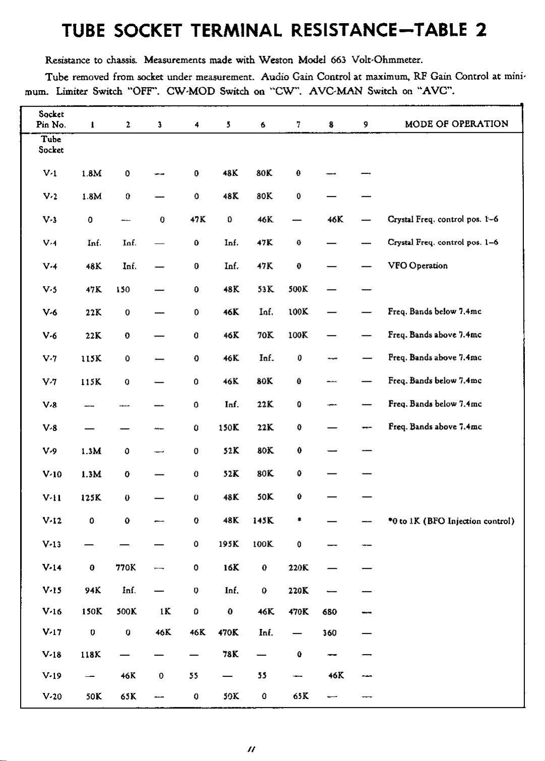
TUBE
SOCKET TERMINAL
RESISTANCE-TABLE
Resistance to chassis. Measurements made with Weston Model 663 Volt-Ohmmeter.
Tube
removed from socket under measurement. Audio Gain Controlatmaximum. RF Gain Control at mini-
mum.
Limiter
Switch "OFF', CW·MOD Switch on "CW".
AVe-MAN
Switchon"AVe".
2
SQcket
Pin
No.
Tube
Socket
V-I
V_,
V-3
V-'
V-'
V-l
V-6
V-6
V-7
V-7
V_,
2 3
l.8M
l.8M
0 0
Inf. Inf. 0 Inf.
<OK
"K
21K
21K
llsK
llSK 0
0 0
0
lnf. 0
130 0
0 0
0 0
0 0
0
"K
0
0
,
<OK
<OK
0
In£.
<OK
<6K
<6K
<6K
<6K
Inl.
6 7
80K
80K
<6K
"K
"K
13K
Inf.
10K
InE.
80K
21K
0
0
0
0
'OOK
lOOK
lOOK
0
0
a
, ,
'6K
MODE OF OPERATION
Crysb.l Freq. control pos.
Crystal Freq. control
VFO
Operation
Frcq. Bands below
Frcq. Bands above
Frcq. Bands above 7.4mc
Frcq. Bands below
Frcq. Bandt below 7.4me
pos.
'.4me
'."me
7.4me
t-<i
1-6
V-'
V-'
V·1O
V·1l
V·12
Y·13
V-I-4-
V·I'
V-16
V-17
V-18
V·19
V·20
UM
I.3M 0 0
12SK
0 0 0
0
..
1S0K
0 0
U8K
lOK
0 0
0
770K
K Inf.
lOOK
<6K
6lK 0
IK
<6K
0
lSOK
0
0
0 19SK
0
0
0 0
<6K
.70K Inf.
l5
52K
52K
<OK
<OK
16K
In£.
78K
SOK
21K
80K
80K
lOK
HSK
lOOK
0 220K
0
<6K
l5
0 6lK
a
0
a
0
•
a
nOK
"70K
0
680
360
<6K
Freq. Bands above
·0toIK (BFQ Injection control)
7.4me
/I
Page 12

VI
ALIGNMENT
'The alignment
ceiver requires
knowledge of
mg a double ruper-heterodyne,
dun
is
~ven
Uncke
ment
Ronnal service
for
extremely long periodsoftime, consequrntly
ofamodem
p~dsion
the
circuiu involved.
more involved
the
communications re-
instruments
than
receiver will stayinalill:n·
and
a thorough
This
receivu,
the
alignment proce-
is
USlal.
be-
ALIGNMENT OF
The
low frequencyIFshouldbealiiflcd
recommended
IF
involves the useofa sweep frequency signal gen-
er.uar
andanoscilloscope. Since these instruments
not avaib.bleatthe
nate
mrthod
crator
and
The additional information
method
for aligning
the
averai:e service stiltion
using an amplitude modulated signal
an
output
meter will
be
ttquired
i1lignment method wiltbecoveredina later
The
signal g£nerator .shouldbecoupledtothe grid
of
the
mixer
tube
VS
th.rough a c:lpilcitance
proximately
be
required 10 milke
.0
I mfd. A miniature tube
the
mixer grid connection avail-
able. Such an ildapter is manufacturedbythe
Manufacturing Co.
nected across
the speaker voice coit.
the
An
output
output
meter shouldbecon-
terminalllofthe
The
receiver controla .mould
nowbeletaIfollow,,:
Control
ScJectivity
Send - Rc:ei
...
-e
CW-Mod
Phasing
AVC-Mm
Audio
Gain
RP Gain
Band Switch.
0;.1
The
signal generator shouldbemodulated 30 per-
centat.400
3 kc position
maximum. Set
kc
and
00
the
of
the
LH,
Ll9,
ducing
control u required
output.
est position,.2Ite.
quency
cycles.
adjust its
output
v:uious
L38, L36
the
signal
Now
for
the
and
the
meter.
:IIlignm~t
tum
muimum
output
Stt
Receive
Mod
Arrow
M",
Set
Stt
US
2.5
Tum
the
advance the
signal generator frequency to
untit some deflectionisnoted
Rdu
and
Ll2
Jiil:enerator
to
prev~t
the
Icleetivity switchtothe
and
.djuat
output.
correct signal frequalCY by the 455
IP amplifier and
should
not
the
frequencyofthe
be disturbed for
Posibon
tat
for
ilpprox..
t<n
-3.45
me
selectivity
mc
RF
to
figure 3
u1justmUits.
for
maximum output. re-
output
U1d
overload
the sillm.l gene-rator fre-
This
lee
the
remainderofthe
frequency IF alignment, unless it shouldbeto recheck
this establishmentofcryltal frequency to make sure
that
the
signal generator frequency
during the alignment.
The
selectivity switchisnow
nrst.
The
low frequency
are
the
alter-
~en
descnbed £rn.
for
the
visual
pangnph.
of
ap-
adapter
will
Alden
receiver
10
volts
switch
to
the
Gain control to
455
for
the
Ioation
Adjust
the
or
establishes
crystal for
L.n.
RF
Gain
excessive
narrow-
the.
the
siKnal R;tnen..tor
low
hou
not drifted
or
realip:nment
pouible
inated.
ment should
should
required readjustment should not
should
awes
ofaputicular
Whenithu
be
be.
aercised
not
be
attemptw.
been
detumined
attempt~
in
ma.king
unle.ss
trouble
lave
that
a great deal
th~
adjmtmenu.
cowl
.1.11
hem elim-
any
realign-
of
caution
mo~
other
as any
than a
5light angular motionofthe adjusting screw.
THE
turnedtothe3kc
L36
Now
IF
STAGES
position
and
L32 are again adjusted for maximum output.
tum
the
selectivity switchtotbe 1.1
and
L42. L41. L39.
Icc
U8.
po!;tion
and adjust L37 for maximum output. Before. changing this
ing the CW-Mod switch
beat with
necessary
check and adjustment of
the
low frequency IF shouldbethe
cr.:pt
amplitudr.:
The
acro"
junctionofR64
the
l«tivity
the signal
L31,
heldtoa very
it
3.5 me
set·up
the BFO should
the
BFO knob diiil
L44
should
be.
be
to
turned
CW
and checked for
at
its
uro
on
by throw-
reading.
adju5ted for zero output.
the
BFO should
be
done with
signal generator carrier unmodulatcd.
Th£
procedure for the visua1 m£thod of aligning
I!ilmeasthe above ex-
that
the adjustments are
and
coincidence
of.
m:llde
for both maximum
the
oscillolcope images.
oscilloscope vertical input should be connected
the
diode detector load resistance. from
and
R65tochassis.
The
high frequencyIfshouldbealigned next. Set
band
switchtothe 7.4 - 14.8 me band.
The
is
LB
3.05
desired
to
switch should
genelOl.tor
and
L34
me
cry5ta1
dose
that
permit
be
in
the3Itc
frequencyto3.955 tnc
for
maximum output.
used in
position. Adjust
the
secood
and
osallator
frequency tolerance. However,
WI
its
oscillator
we
as a frequencY standa.rd,
frequency
be
1;UO
1'h.UI
the
the
The
adjust
exactly
hereinafter described, this may be accomplished by
adjusting capacitor
exact procedure is as follows;
mconthe
by
means of a jumper, the center and the open tennin-
3.45
als on llwitch 54atthe rear of
a two foot length
tuminal
on
switch
a
Now
and
the
3.S me oscillator tube
on
CW
beu
noteisheard in the headphonesorspeaker.
throw
couple a 1.0mcfrequency
put
tenninal.
R'emove
test lead.
the
If
CIOI,
underneath the chusis.
Set
the
receiver
The
to
- 7.4 me band. Temporarily connect,
the
tuning unit. Attach
of
insulated wire to
the
antenna
dress the free end around the tube shield
V8
with
the
CW-Mod
rock
the
tuning control slightly until
the
CW
-Mod
Adjust ca.pacitor
jUlrlper from 54
appreciable adjustmentofCtOI
switch
.!.ta.ndard
ClOI
and
remove
to
Mod
to
the antenn], in-
for
urn
the
two
and
beat.
foot.
was
quireditis advisilble to repeat the high frequency IF
alignment.
The
3.5
me oscill",tor
quency standardatmultiples of
upwards,
tengthofwire
by
temporarily connecting the
<l.S
deacribed above.
mOlY
now
3.5
be
uled
mc from
all
two
a fre-
10.5
foot
If
st.-
is
if
as
7.0
~
me
Page 13

ALIGNMENT
To
adequately align the RF Amplifier and
OF
THE
RF
AMPLIFIER &
HF
Os-
cillator an accurately calibrated signal generator and
an
output
quired
justments
Uld Figure 3 should be made in following this part
the
alignment which will now be described for one
frequency
followed for
To
is
coupled to
100 ohm
modulated
meter
The
receiver controls should be set as follows:
Control
meter are required.
are shown in table
is shown in Figure3.The
band.
The
same
the
other frequency bands.
align the .54-1.35
the
me
antenna input terminal through a
carbon resistor.
30
percentat400 cycles and
connected
Selectivity
Send-Receive
acl"Olls
tne
CW-Mod
AVC~Man
Audio Gain
RF
Gain
Band Switch
Limiter
The
frequencies re-
3.
The
locationofthe
useofTable 3
procedure should then be
band the signal generator
The
generator should be
the
output
fcceiver
output
terminals.
Position
Jkc
R.et:eive
Mod
See
Text
Set for approx. 20 volts
See text
set for band to be aligned
off
ad·
of
HF
OSCILLATOR
Set
the
receiver and signal generator dials to .56
The
RP
Gain control should be set at maximum and
the
AVe
- Man .switch set on
adjustment
showninPigureJ,should now be set for
maximum output.
L
adjwstment:.!l
.mould be set for maximum output.
Then
Ave.
the
Ant., 1stRFand 2nd
The
HP
receiver and signal generator dials are now set
me and
the
e adjustments, shown in FigureJ,should
me.
Osc. L
RF
The
to
1.3
be adjusted for maximum output in the same order,
beginning with
ing
the
e adjustments for the
RF.
This
til no increaseinoutput can be realized.
Man switch should thenbeset to
generator should be set
volts.
The
checked for maximum output, adjusting
control as found necessary
the
Osc C adjustment and then mak-
Ant,
1st
RF
and 2nd
procedure should be carefully repeated un-
The
Ave-
Man
and
the
signal
for
approximately:3micro
L and e adjustments should now
the
RP Gain
to
maintain the output at
approximately20volts.
Following the frequencies, shown in Table
the
remaining bands using
the
same procedure
3, align
above.
be
as
TABLE
RF
AND
HF
OSCILLATOR ALIGNMENT FREQUENCIES
FREQ. BAND
INMC
RFfSHF
ADJUST
RFfiHF
ADJUST
OSC
LAT.
OSC
CAT.
.H-1.35
.56
1.3
APPROXIMATE SIGNAL
Output
30
percent at 400 cycles. Signals applied to tube grids through a
AVe-MAN
BAND
measured acroas a 600 ohm resistive load
SWITCH
My
A,y
1.35-1..045
US-1..04S
1.3S-3..045
1.3S-3."'5
1.3'-3.45
7."'0-'.04.8
7.
.040-1.04.8
switch on
me:
me
me
me
me
me
me
MAN.
1.35-3..45
1..
3.'
TABLE
INPUT
CW-MOD
FREQUENCY
Audio
-400
cyda
Audio
.0400
cycles
Mod
RF
.455
k" Pin 1.
ModRF.04SS
Mod
RF
ModRF
Mod RF4"Ite
Mod RF 3.95S
ModRP
"'''
.o45S
1.955
h:
ke
k.e
AT
switch on
me
me
3.45-7.'"
3.75
7.1S H.S 29.0 S2.0
No.4
IF
at
No.3
AND
ADJUSTMENT DESIGNATIONS
7
....
-+U
7.'
'"
loP STAGES
output terminals
.01
MOD,
RP
INPUT
PinS,V17
Pin 2, V16B
PinI,VIO 6000
PinI,V9
Pin1,V7
Pin 7,
Pin 7, VS
Pin 7,
FOR20VOLTS
of
receiver.
mfd capacitor. Selectivity switchat3
Gain and Audio Gainatmaximum.
TO
Vll
V,
V6
14.8-29.7
13.0
RP
APPROX.
l.'
150 microvolts
29.7-''''.0
10.0
OUTPUT
signals modulated
INPUT
~I.
.J
~I.
.35
volts
miC1'ov())ts
110 microvolts
-40
miel'OV(llts
6'
mierovoltl
.040
miel'OV(llts
kc
13
Page 14

e
e e
L41
L42
OT50
e
L38 L39
OT40
®
L37 L38
OT30
e
e[]8
@
e
I
LM
L331
ona
Ctot
r-----~;)
' ,
' ,
lee!
L:
________
@
"",
~
0
GND
a
8
~c
0
ANT
0
L
0c
0
15
0
0
0
0
L32
0
T'
0
L3'
0
@~
2R
0)~
H
8?
v
1"'-
\.
OOOOOgl
000000
000000
123456
e 0
'\
T8
/
~
.3
,/
0
L44
00
TOP VIEW
SHOWING
•
AUDIO
CURVE-Audio
---------
5
ai
c
o
z
CURVE - Owroll
ALIGNMENT
AND
frequency amplifier.
Selectivity switchin13kcposition.
RF
Gain
Output
Audio gain control01maximum
OF
CHASSIS
ADJUSTMENTS
riG.
OVERALL FIDELITY CURVES·
fideliiy
set
measured
for
3
at
20
volts
across
2.5
mc.
outputat400
Q
600
Inputtophono
Modulation
ohm
resistive load.
for
both
30
cycles.
curves.
-
terminals.
percent.
,
:y
5
'00
CYCLES
F'IG.4
PER
<000
SECOND
m,ooo
Page 15
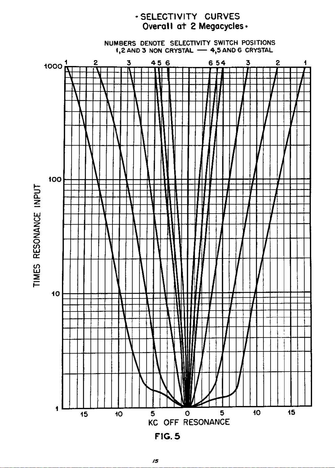
• SELECTIVITY CURVES
Overall
at
2 Megacycles.
w
u
Z
<t
Z
o
13
a::
iOO
too
NUMBERS
i.2
1
0
2 3
DENOTE
AND3NON
456
SELECTIVITY
CRYSTAL
-
SWITCH
4,5
AND6CRYSTAL
654
POSITIONS
3 2
1
I-IIt
III
III
13
::E
;::
10
11111
,
tN-
I
~
....
1
15
10
505
KC
FIG.S
OFF
RESONANCE
J
10
15
/5
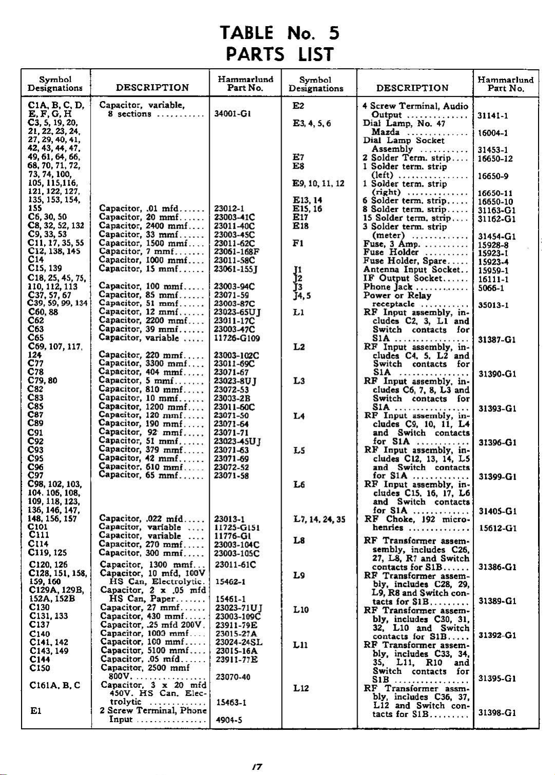
Page 16
VII
CONVERSION OF
MODEL
The
SP·600 Receiver is designed for either table
nbinet
ordered, the receiverisr.ot
'Cover
nck
il
cover pla.te since in most
inet type.
conversion(0rack mounting where table
been
insu.lling the cover kit; To install
piau,
by
of
two
or
IOlck
mountinll_
p~te
since
the
cabinet serves this purpose.
models are ordered the receiverissupplied with
bottom cover plate,
A cover plate kit is provided.onsepara.te order, for
ordered and where the covers are desired.
The
following inSUUctions
remove the two
removing
the
nut
the
JarK"t
side
plate brackets with
but
rtar
three
.screwsatthe
mountinr
RECEIVER
When
supplied
is not supplied with a top
~ses
shouldbefollowed
corner
brackets and replace these
the
uble. models are
with
• bottom
the
rack.isof
the
nul:
lower rear ends
two slightly shorter
the
moods
bottom cover
plate
bad:ets
TABLE
FOR RACK MOUNTING
from
the
kit, using the same ~ws. Remove the
lockwamer from the screw, nearest the bot,
chassis, holding capacitor C1St (see
from the kit, using
nut
a.nd
washer were removed. with the
(smaller end)ofthe
CQver
plate is now installed using
the
bottomofthe receivertothe
To
in.so.lI
the
tOp
cover plate assembly, place
being
and with pressure appliedatthe rearofthe
front panel, .secure
the
four
6-H
5(:r~$
the
tapped holes in
side mounting bn.ckets.
When
cab-
have
when
one!
nut and
tom
edgeofthe
bottom of chassis photograph). Insta.ll the short angle
bracket,
which
ta.pped
the
The bottom
10,32 screws from the kit
that
previously held
cabinet.
the cover with tbe angles
&:husis
plate.toMigbdy compress the rubber channel
the
rearofthe
place with
them in
dearance holesInthe
the
same screw from
bracket replacing the nut.
the
iUld
the
two lO'32 screws
downwa.rd.
from the kit, engaging
the
brackeu through the
the
auembly in
to~rd
against
five
the
'0
Page 17
TABLE
No.5
Symbol
Designations
CIA,
B, C, D,
E,F,G,H
C3,5,
19,20,
21,22,23,24,
27,29,40,41,
42,43,44,47,
49,61,64,66,
68,
70, 71, 72,
73,74,100,
105,115,116,
121,122,127,
135,153,154,
m
C6,
30,
50
ca, 32, 52, 132
Cg,
33,
53
Cl1,11,35,SS
el2,
138,
145
Cl.
CIS,
139
CIS,
25,
lIO,
C37. 57,
C39,
C60,88
45,
112, 113
61
59, 99, 134
CO2
C63
COS
C69,
107,
117,
12.
cn
C70
C79.80
CO,
CO,
CO,
C07
CO,
COl
CO2
C93
COS
C96
C97
Cga,
102, 103,
104.106,108,
109,118,123,
136,
146,
148, 156, 157
CtOI
CUI
ell4
C119,125
e120,126
el2a,lSt,ISS,
159, 160
C129A,
IS2A,152B
el30
Cl3I,133
CI37
C140
C141,142
C143,
C144
elSO
C161A,B.C
El
147.
12gB,
149
DESCRIPTION
Capacitor,
S
sections
Capacitor,
Capacitor,20mmf
Capacitor,
Capacitor,33mmf
Capacitor,
Capacitor,7
Capacitor,
Capacitor,15mmi
75,
Capacitor,
Capacitor,85mmi
Capacitor,51mmf
Capacitor,12mmi
Capacitor,
Capacitor,39mmf
Capacitor,
Capacitor,
Capacitor,
Capacitor,
Capacitor,S
Capacitor,
Capacitor,10mmi.
Capacitor,
Capacitor,
Capacitor,
Capacitor,
Capacitor,51mmf
Capacitor,
Capacitor,42mmi
Capacitor,
Capacitor,65mmi
Capacitor, .022
Capacitor,
Capacitor,
Capacitor,
Capacitor,
Capacitor,
Capacitor,10mfd,
HS
Capacitor,
HS
Capacitor,27mmf
Capacitor,
Capacitor,
Capacitor,
Capacitor,
Capacitor,
Capacitor•.05
Capacitor,
800V
Capacitor,
450V.
trolytic
2
Screw
Input,
variable,
.01
mfd
2400
mmf
1500
mmf.
mmi
1000
mmf
100
mmf
2200
mmf
variable
220
mmi
3300
mmf
404
mmi
mmi
810
mmi
1200
mmi
120
mmi
190
mmf
92'
mmf
379
mmf
610
mmf.
mid
variable
variable
270
mmf
300
mmf
1300
C;I,n,
El~ctrQlytic.
2 x .05
Can,
Paper
430
mmi
.25
mid
100:1
mmi_
100
mmi
5100
mmi
mid
2500
...
HS
Terminal,
mmf
,....
3 x 20
Can.
mmi
200V.
..
Phone
.
100V
mfd
.
.
....
mfd
Elec-
Hammarlund
.
3400I-GI
.
23012-1
.
23003-41C
.
23011-40C
.
23003-45C
23011-62C
.
23061-Hi8F
.
23011-58C
.
23061-155J
23003-94C
23071-59
.
.
23003-87C
.
23023-65UJ
2301l-17C
.
.
23003-47C
.
11126-Gl09
.
23003-I02C
.
23011-69C
.
23071-67
.
23023-8UJ
.
23072-53
.
23003-2B
.
23011-60C
.
23011-50
.
23011-&4
.
23071-71
.
23023-45UJ
.
23071-453
.
23071-69
23072_52
.
23071_58
23013_1
.
.
11725-0151
.
11776-01
.
23003_104C
.
23003-105C
23011-61C
.
15462_1
.
15461-1
.
23023-71Uj
.
23003-109C
23911-79E
23015_27A
23024-24SL
.
23015-16A
23911-77E
23070-40
.
15463-1
.
4904·5
PARTS
Part
No.
LIST
Symbol
Designations
E'
&3,4,5,6
E7
EO
E9,
10,11,
E13,H
E15, 16
E17
E18
Fl
n
J4,5
Ll
L2
L'
L.
L5
L7,
14, 24,
LO
L'
LIO
LU
LI'
4
Dial
Dial
2
1
12
1
6
8
15
3
Fuse,
Fuse
Fuse
Antenna
IF
Phone
PowerorRelay
RF
RF
RF
RF
RF
RF
35
RF
RF
RF
RF
RF
RF
DESCRIPTION
Screw
Terminal,
Output
Lamp,
]4azda
Lamp
Assembly
Solder
Solder
(Jeft)
Solder
Solder
Solder
Solder
Term.
term.
term.
(right)
term.
term.
Solder
(meter)
receptacle
cludes
Switch
SIA
cludes
Switch
SIA
cludes
Switch
SIA
cludes
and
for
cludes
and
for
dudes
and
for
henriel
sembly,
27,
contacts
bly, includes C28, 29,
L9,R8and
tactl
bly,
32,
contacts
bly,
35,
Switch
SIB
bly, includes C36, 37,
L12
tacts
tenn.
term.
3 Amp .
Holder
Holder,
Input
Output
Jack
Input
C2.3,Ll
Input
C4.5.L2
Input
C6,7.8,L3and
Input
C9, 10, 11,
Switch
SIA
Input
C12. 13, 14,
Switch
SIA
Input
CIS. 16,
Switch
SIA
Choke,
TranlfClrmer
includes
LB,
R1
ior
Transformer
for
Transfarmer
includes C30, 31,
LI0
Transformer
includes C33, 34,
Lll.
Transformer
and
for
Audio
No.
47
..,..
Socket
strip
strip
.
strip
strip
strip
strip..,.
strip
Spare
Socket..
Socket
usembly,
contacts
assembly,
contacts
assembly.
contacts
aSlIcmbly,
contacts
assembly,
contacts
assembly,
17,
contactl
192
micro·
assem·
and
Switch
SIB
assem-
Switch
SiB
assem-
and
Switch
fQr
SiB
assem·
RIO
contacts
Switch
SIB
, .
and
and
C26,
con-
.....
and
assm·
con-
.
.
.
.
.
.
.
.
.
.
.
in-
for
.
infor
.
infor
.
inL4
.
in-
L5
.
in·
L6
.
..
.
.
for
.
.
Hammarlund
Part
No.
31141-1
16004-1
31453-1
16650-12
16650-9
16650-11
16650-10
31163-01
31162-01
31454-01
15928-8
15923_1
15923·4
15959-1
16111-1
5066-1
35013-1
31387-01
31390·01
31393-G1
31396.01
31399-01
31405-01
15612-01
31386-01
31392-01
31395-01
31398_GI
17
Page 18
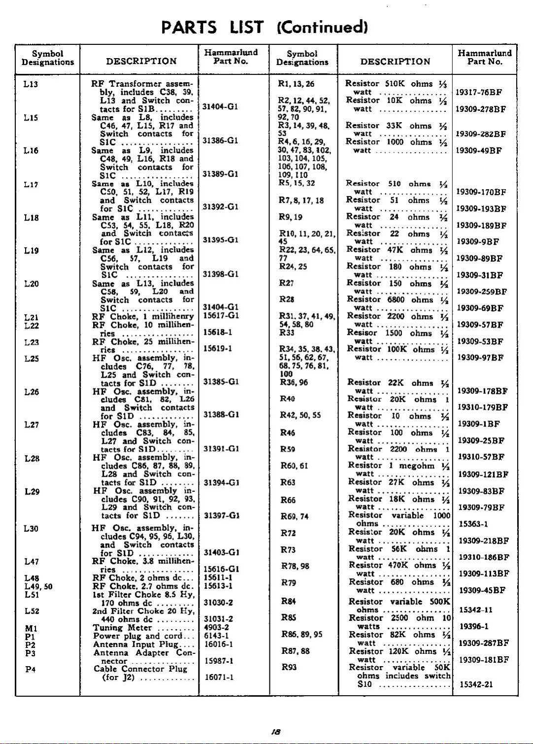
PARTS
LIST
(Continued)
Symbol
Designations
L13
LIS
LI.
LI.
Ll9
L2Q
L21
L2Z
L23
L25
L2.
L27
L28
L29
L30
L47
L48
L<49,50
L51
L52
MI
PI
P2
P3
"'
DESCRIPTION
RF
Transformer
bly,
LI3
tacts
Same
C<46,
Switch
includes
and
for
all
47,
Switch
SIB
LB,
LIS,
contacts
assem-
e38,
includes
Rl1
SIC
Same
Same
Same
Same
Same
RF
RF
RF
HF
HF
HF
RF
RF
RF
2nd
Tuning
as
C48,
Switch
SIC
eso,
and
for
C53,
and
for
C56,
Switch
SIC
e58,
Switch
SiC
Cboke,
ries.., .
ries
cludes
L25
tacts
dudes
and
for
HF
cludes
L27
tact$
HF
cludes
L28
tacts
HF
cludes
L29
tacts
cludes
and
for
Choke,
ries
Choke,2ohms
Choke,
Ist
Filter
170
+40
Power
Antenna
Antenna
nector
Cable
(for
L9, includes
49,
L16,
RI8
contacts
a.
LIO,
52,
includes
Ll1,
contactlJ
51,
Switch
SIC .
all
Lll.
5-4,
Switch
SIC
as
51,
includes
55, LIB,
(;onta~s
L12, inc1udcli
L19
contacts
as
LI3,
59,
includes
L20
contacts
1
Choke,
Choke,
Osc.
and
Osc.
millihenry
10
millihen-
25 mUlihen-
alsembly,
C76, 77,
Switch
f(X"
SID
assembly,
C81, 82, L26
Switch
contacts
SiD
Osc.
assembly,
C83. 84,
and
Switch
for
SID.
Osc.
assembly,
C86, 87, 88,
and
Switch
for
SiD
Osc.
assembly
C90, 91, 92,
and
Switch
for
SID
.......
Osc.
assembly,
C94, 95, 95, L30,
Switch
contacts
SID
3.8
millihen·
2.7
ohms
Choke
ohms
Filter
ohms
Meter
plug
Input
Adapter
_
Connector
}2)
dc
Choke
dc
and
....
8.5
20
cord.
Plug.
con-
Rig
con-
con-
con-
con-
de .
Con-
Plug
39,
.
and
for
.
and
for
.
H2O
.
and
for
.
and
for
"
.
in78,
.
in.
.
in85,
in-
89.
.
in93,
in-
.
.
de.
Hy,
.
Hy,
.
.
Hammarlund
Part
No.
31404-01
31386-01
31392-01
31395·01
31398-01
31404-01
15617-01
15618-1
15619·1
31385-01
31388-01
31391_01
31394-0]
31397-01
31403-01
15616·01
15611-1
15613·1
31030·2
31031-2
4903-2
6143-1
16016-1
15987.1
16071-1
Symbol
Desirnations
RI,
13,
26
R2, 12, «, 52,
57,
S2,
90, 91,
92,70
R3, 14, 39, 48.
53
R4, 6. 16, 29,
30,47.83,102,
103, 104,
106,107,108,
109,110
R5, IS,
R7,8,
R9,19
RIO, 11,20,21,
R22, 23, 64. 65.
"
71
R24,25
17,
105,
32
18
R27
R2I
R31. 37, 41, 49,
54,58,80
R33
R34. 35, 38. 43,
51,56,62.67,
68,75,76,81,
10'
R36,96
R40
R42,
SO,
55
R46
R"
R60,61
R.3
R.6
R69,74
R"
R73
R78,98
R70
R84
R65
R86, 89,
R87,88
R93
95
DESCRIPTION
Hammarlund
Resistor
watt
Resistor
watt
Resistor
watt
Resistor
watt
Resistor
watt
Resistor
watt
Resistor
watt
Res;stor
watt
Resistor
watt
Resistor
watt.........
Resistor
watt
Resistor
watt
Resistor
watt
Resiaor
watt........
Resistor
watt
Resistor
watt...
Resistor- 20K
watt............
Resistor
watt........
Resistor
watt
Resistor- 2200
watt.
Resistor- 1
watt
Resistor
watt.
Resistor
watt...
Resistor
Ohmli 15363-1
Resistor- 20K
watt.
Resistor
watt......
Resistor
watt
Resistor
watt......
Resistor
ohms
Resistor
Resistor
Resistor
Resistor
S10K
ohms
!1
10K
ohms
33K
ohms
1000
ohms
__
.. ..
..
510
ohms
.
....
51
ohms
24
ohms
....
,..........
22
ohms
.....
47K
ohms
180
ohms
150
.....
.....,.....
.....
....._....
watts
watt
watt
ohms
S10 15342-21
ohms
,...........
6800
ohms
2200
1500
lOOK
22K
10
100
. 19310-57BF
27K
. . .... . . .. . .... . 19309-83BF
18K
variable
..
5CK
470K
680
variable
2500
82K
120K
variable
includes
,.....
ohms
,......
ohmlJ
.
...
ohms
ohms
..
ohms
ohms
.
.... ....
ohms
.... . . . . . .. 19309-2SBF
ohm.
megohm
'... 19309-12IBF
ohms
ohms
. 19309.79BF
ohms
. 19309-218BF
ohms
..
ohms
. . . . . . . ....19309-113BF
ohms
. 19309-45BF
ohm
ohms
.
ohms
switch
19317-76BF
Y2
19309-278BF
7'2
19309-262BF
n
19309·49BF
%
193og_170BF
n
19309_193BF
7'2
19309.189BF
Y2
19309-9BF
7'2
19309-89BF
7'2.
19309-31BF
tii
19309.259BF
7'2.
19309-69BF
7'2
.....
19309·57BF
7'2.
.....
19309-53BF
Yz
19309_97BF
7'2
. 19309-178BF
1
.....
19310-179BF
7'2
19309-IBF
Yo:
1
~
7'2
tii
1000
7'2.
1
1!)310-18CBF
y,;
y,;
500K
10
tii
..
!1.
SOK
15342-11
19309-287BF
19J09-181BF
Part
19396-1
No.
/8
Page 19

PARTS LIST (Continued)
Symbol
Desiandions
R"
R07
R99
RI01
SlA,
B, C, D
'2
53
'4
SSA, B, C
56.9
57
58
'10
'11
Tl
T2
T3
T4
T5
TO
T7
T8
Xl,2,6,7,8,9,
10, 11, 12, 13,
14,15,18,20
X317,19
DESCRIPTION
Resistor
1100
watt
Resistor
Yz
Resistor
Rellistor
ohms
Switch,
watt
360
.,"
bue
3.3
.........•..•.
ohms1watt
vil.riil.ble
"." .
and
assembly
Crysal
Crystal
Swit~h.
Selectivity
TonIe
Toggle
Toggle
Switch
Switch,
Mixer
IF
Crystal
IF
selector
switch
~onver1lion
sWltchmg
tion
switch, 3
Switch
Switch
Switch
"ON-OFF"
of
R93
return
bly, includes C67,
bly,
99, L33,
DPDT,
plate
70,
L31,
32,
Transformer
includes C97,
34,
Filter
includes
112,
R41,
Transformer,
C1I7,
CI07, 110,111,
113,
114, L36,
Ya
118.
coil
L38, 39, 40,
Same
Beat
Transformer,
Transformer.
Tube
Tube
as
C123,
L41, 42. 43, R54
assy.,
131,
45. 46. R76,
Output
T4,
124,
Frequency
includes Cl3Il,
132, 133. 134,
socket.
socket.
octal
ohms
me,ohms
25K
sprine:
switch.
set-
SPST
DPST
DPDT.
part
....
spring
assem·
R31.
assem-
R35 .
assembly,
includes
119,
120,
R49.,
....
includes
125, 125,
.....
Osc.
L44.
77
Audio
Power
miniature.
Y2
19309-208BF
"
19309-133BF
19310-211BF
15342-4
31234-01
.
15879·1
31469-1
.
15862-1
.
.
15856-1
15864-1
..
...
15866·1
15867-1
.
15880-1
69,
31183_01
"
93.,
31116-01
37,
.
31114-GI
31102-01
31102-Gl
.
31106-01
,.
31029-2
.
31086-2
15989.4
16082-1
Hammarlund
Part
No.
Symbol
Designations
X4
XS
X16
X2l
Vl,2,3,4.5,6
Y7
Y8
Miscellaneous
DESCRIPTION
Tube
socket,
ceramic,
shield
Tube
socket,
ceramic,
shield
Tube
socket.
Crystal
for
crystalsVIto
Crystal,
specify
quency
Crystal,
Crystal,
Wrench,
Wrench.
Wrench••et
Snap
Button
Shaft
Coupling,
Shaft
Coupling. flexible,
soft
Shaft
Coupling. flexible.
stiff .
Spring,
coil
assemblies
Sprinl,
coil
Sprine.
transformer
Spring,
switch
Spring,
Spring,
detent
Knob.
frequency
Knob,
tuning
Knob&:Skirt
Knob&:Dial
Knob&:Di..l
(Audio
Knoba:Dial
(Crystal
Knoba:Dial
(Beat
Knoba:Dial
(Selectivity)
Chart,
frequency
Spring.
miniature,
less
miniature,
with
"Noval"
socket, ceramic,
order
signal
3.5mc
455kc .
set
screw
set
screw
screw
Plue
retainer
retainer
grounding
shields
conversion
....
indicator
band
change
lock
(larle)
(RF
Gain) .
Phasing)
Frcq.
anti-backb.lih
.
special,
..
riiid.
for
for
....
slide.
control
O.e.)
control
center
center
V6
fre-
No.6
NO.8
No.
RF
RF
for
IF
O
..
in)
...
....
...
Hilmmarlund
15989·5
.
15989-3
..
16100-1
16092-5
.
31473-stlec.
31130·1
31471-1
11806·2
11806-3
10
11806
_
2%19_2
31275_01
415_03
.
415-02
.
.
31004-1
31023-1
..
31125-1
31126-1
.
31205-1
31434-01
.
31462-01
.
31215-01
31227-01
31227-02
31227-03
312Z7-G4
.
31227·05
31463-1
31239-1
P,.rt
No.
....
/9
Page 20
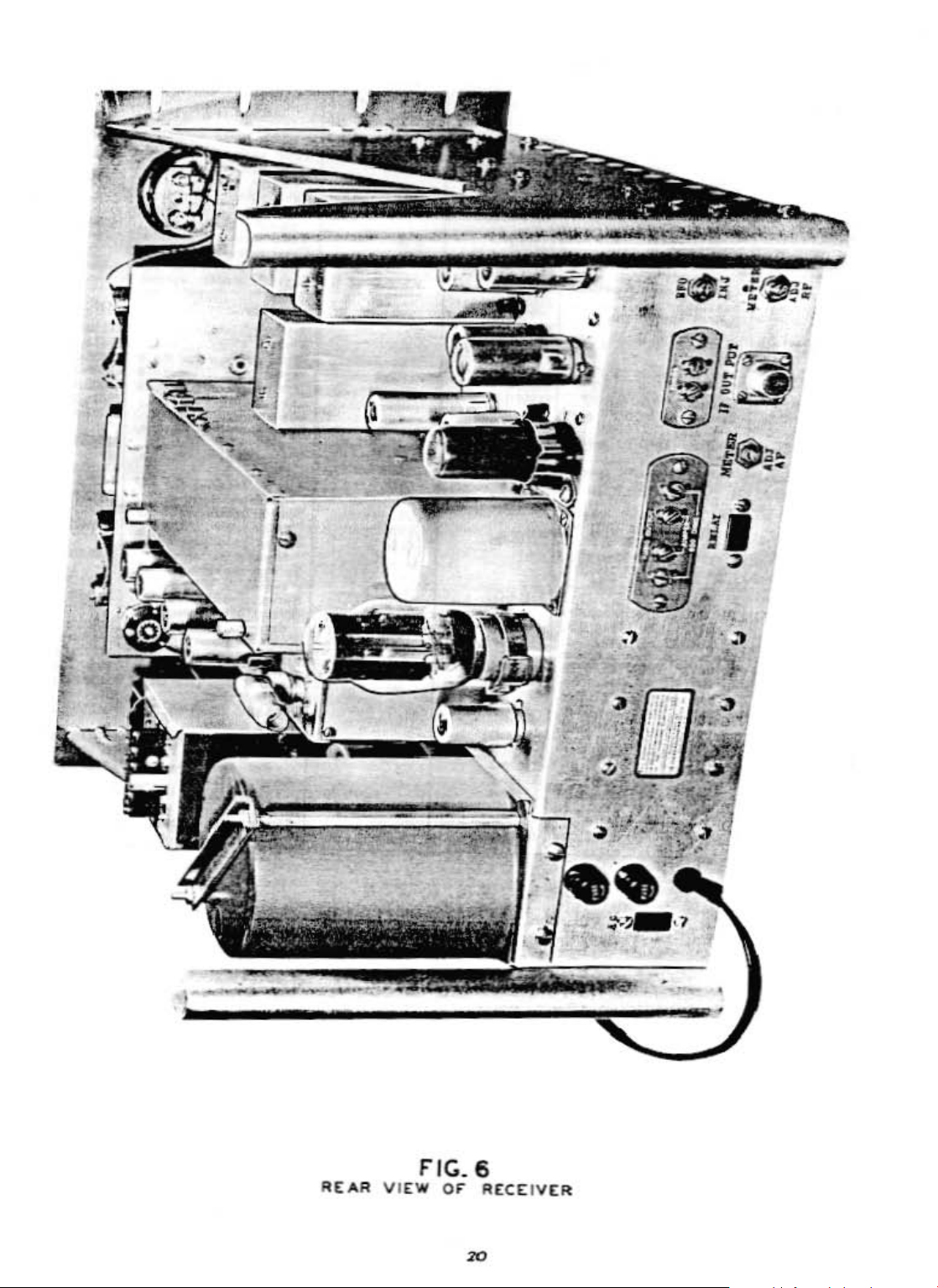
~
-:,:
,
~;
,
"
.
,
•
•
.'J
;~
~'fY
G·
.:~~
: .
~
0
I
-
..
'@3'"
~
.,
"
J'
~
.
,
'.
AtAR
\/'1[W
flC.6
or
R[C£IV[R
Page 21
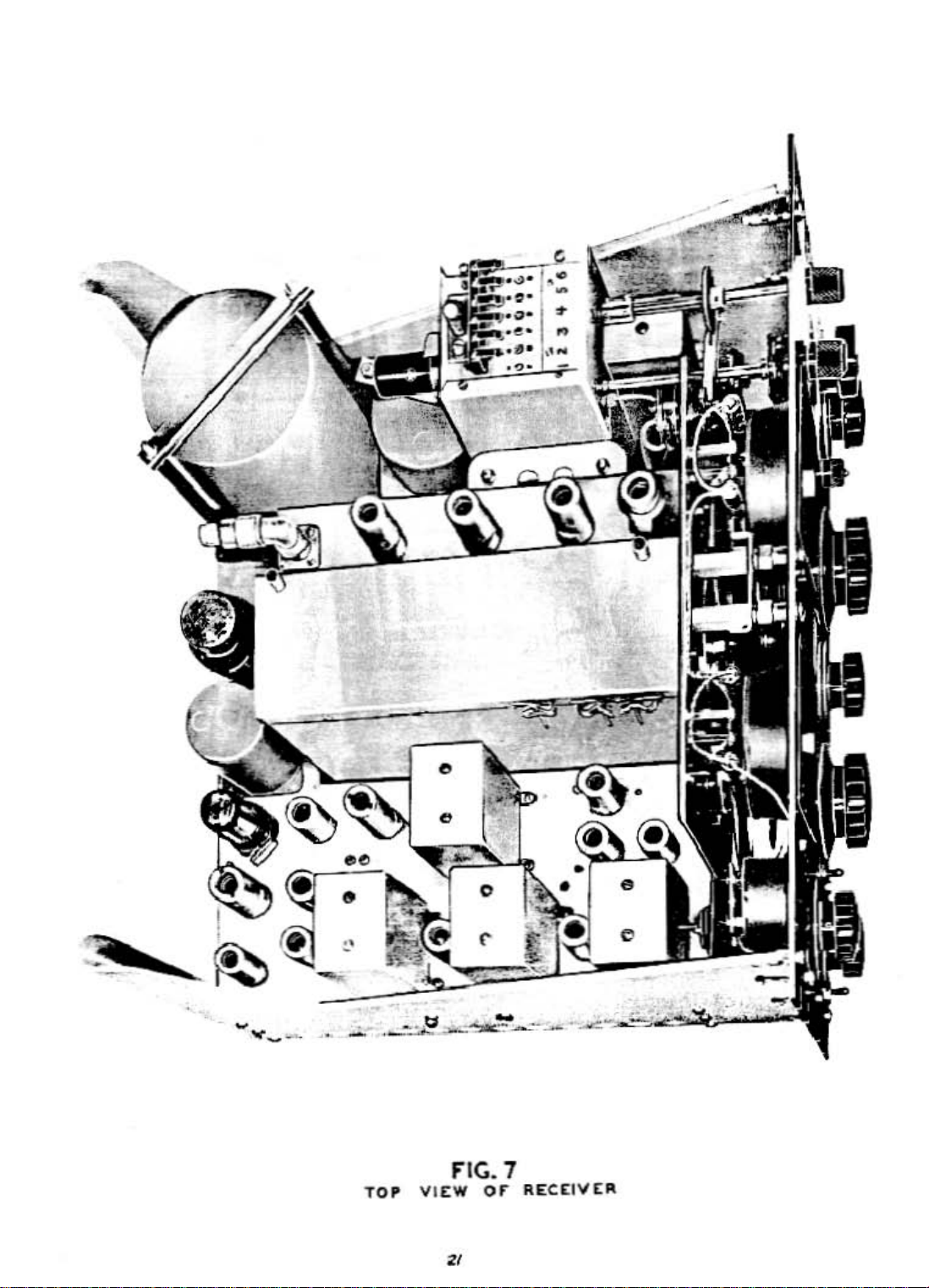
-"
•
....
_
....
-,
-
FIG.7
'0'
Vll::W
or
RECelV[R
Page 22

;-:---~~--~~--_._--=---~
TOP
CAPACITOR
VIEW
FIG.
or
SHIELO
&
l'tt.C[lV[l't
AUAOV[D
Page 23

"--
BOTTOM
VIEW
F'
IG. g
Of'"
R[CI:IVI:F1
'P-600-Jll.
Page 24

!!lOTTO'"
TU
....
ING
UNIT
rIG.
VIEW
5H1ELD
10
or
IUCCIVEIt
IlE~OV[D
Page 25

, , .
"
•
",0
RED
"
®
9
"
BL
'OK
c
w
"
"
CO2
" "
A
K-WHIT
REO-BLACK
'0
L.
.<
REO-WH
R93
R
CI61
13.
VI'
MAIN
WIRING
CABLE
o
"'@'"
0 0
o 0
OSCILLATOR
TERMINAL
LOCATED
ON
BOTTOMOFCHASSIS.
~
OVER
NOTE: SWITCHISMOUNTED
ON
TUNING
BY
e.~3
1-2
0
BANDSWITCH
CL.OSED
CLOSED
UNIT
BELOW
ABOVE
~O
~
•
O~
0
OPEftATED
t;
b>
0
RED
SOCKETS
[!H~Qi.[D.J
REEN
BOARD
va
a
0
V6
-GR
£L-RED
7.4
hie
7,4
Me
I\
~)
CIOI
0
0
r
~"JJI
~
~
0
J.-.
WHITE-BLACK
WH-GREEN
P
S82
I
•
,
,
"
o
BLACK
,
.,
RB'
'---
__
L
2
~A<'
-!~
"
I
i:
"
"
27-28
Page 26
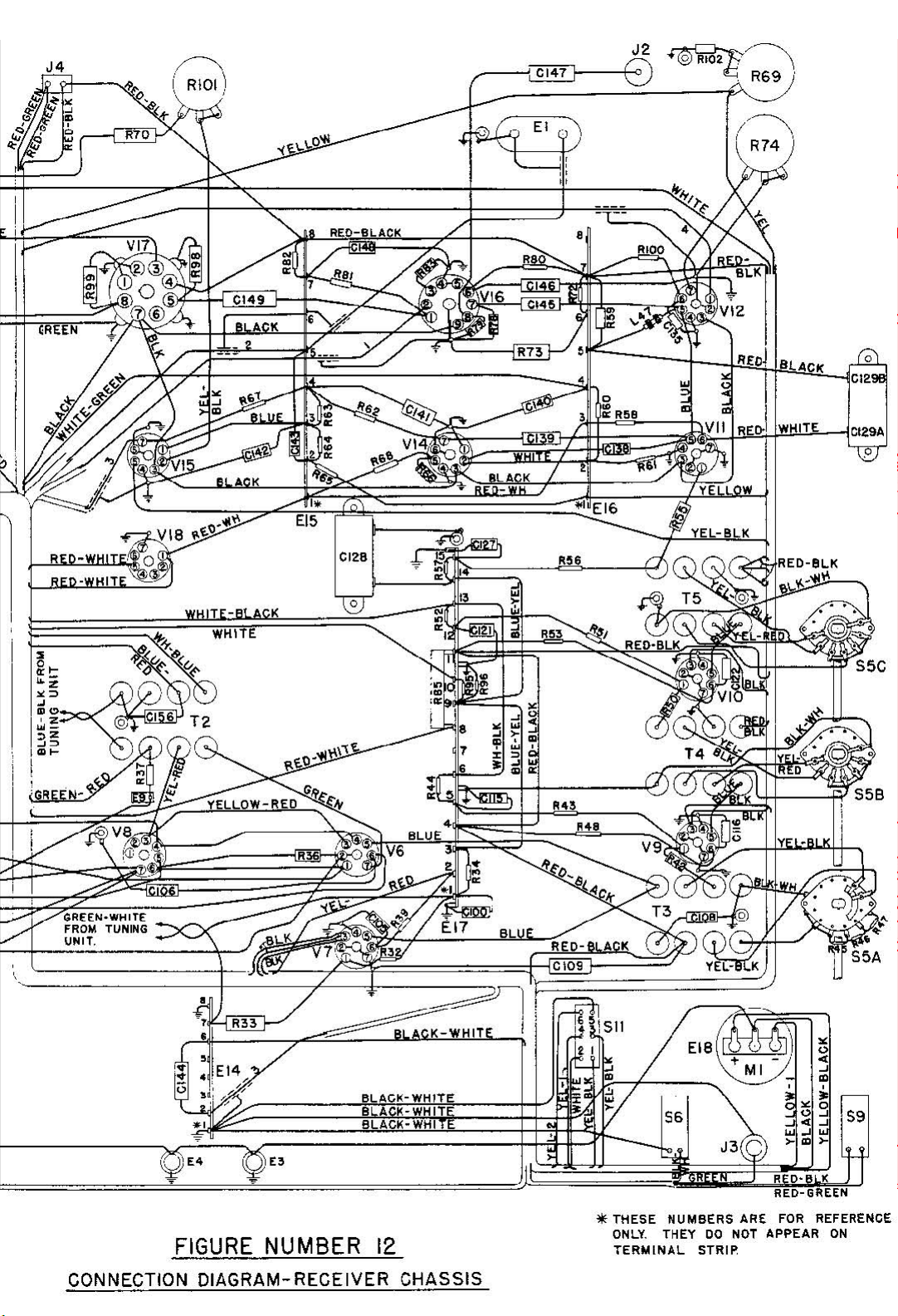
/\
I R74 '
BLACK
WHITE
,@
'12"
Cl29A
'5
FIGURE NUMBER
12
CONNECTION DIAGRAM-RECEIVER CHASSIS
*THESE NUMBERS ARE
ONLY.
THEY
DO
NOT
TERMINAL
STRIP
RED-GREEN
FOR
REFERENCE
APPEAR
ON
Page 27
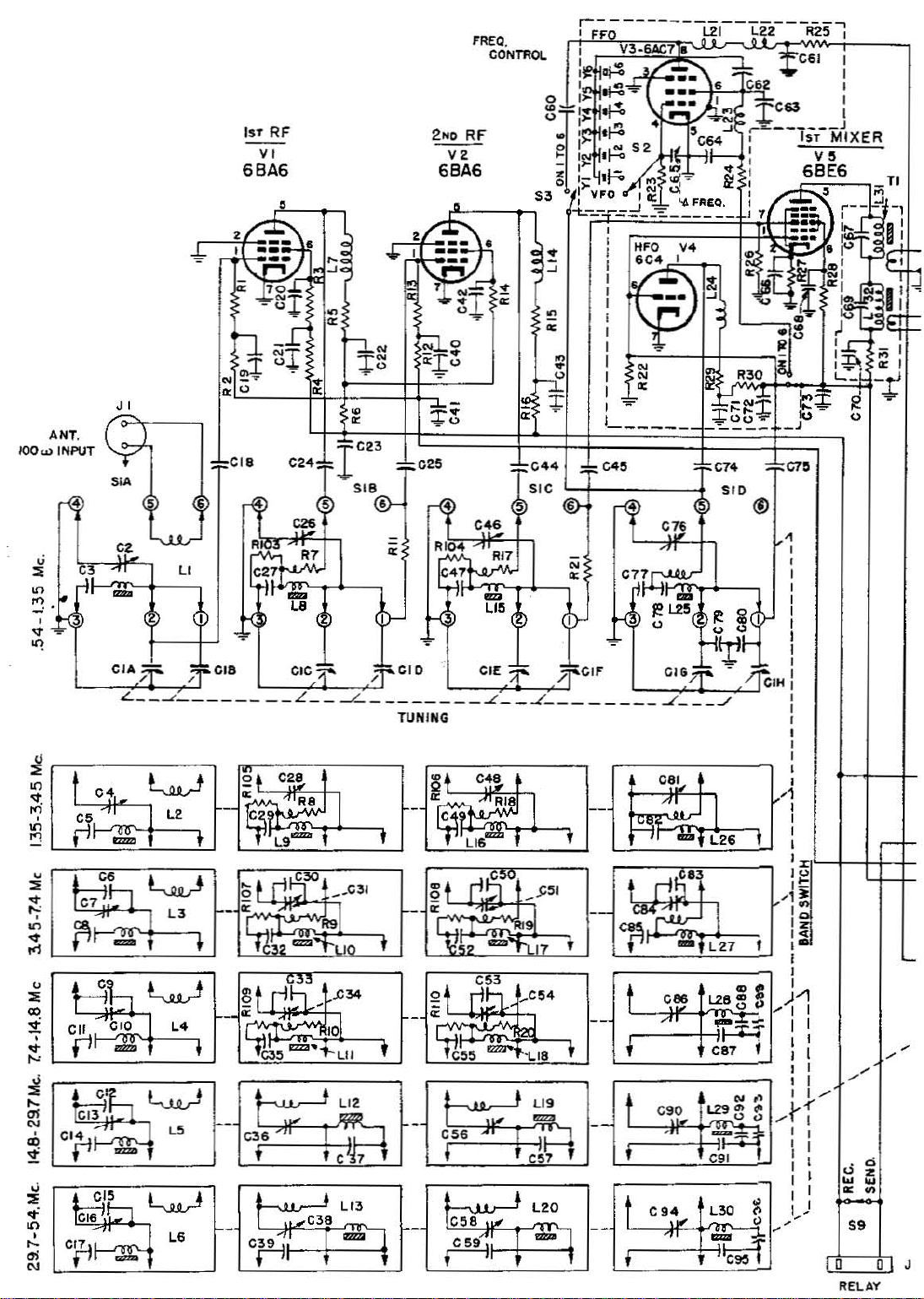
1ST
RF
VI
6BA6
~
V2
6BA6
,
•
•
,
u
~
"
~
'"
,
..
'1
~
:il
'.'
(
f2
~
CIA}"
L
__
...
..J
u
CI.
(0
I
~
cIa
-
L~-'-_'L,,9'-.:._·_!~,,_
_
C24
C26
I~
IIc27
§I
~,
t,l.""
~
L.
elc.1*"
C2.
r''=1
CI'ZZJ""I
.7
L
__
,
~1_C31
044
-C45
SIC
=-t--::---j
C4
•
"i'CIO
-L
TUNING r
1
__
,--,1
-
_
~,
In'
erE
..L__-"____
l!l~
.~~--~~==;-~::L~2~O=::;
r~
¥.,l;? IllZ/ll
@ If
r'"
/j'CIF
~t
1'7
,
--
" - ,
Li.
~L2',
~
-
_
-1
~
~
p~
074
mol
't1~~~'
Cl~;r.
SID
../
,
07.
<'J
•
,
,
I
,
i
~
,/
CIH!
:
I
,
I
I
,
'1
--
f-,j~§~IL-lt:j:+
:
.q
I -
I
"
c,.
err
~
fi
-
~
L.6
'2
030
, , ,
~
c~
t·
I
"'"
, ,
o~c
- • --
C!55
COO
~
l
C!58
l
-.J
uI'
C!54
1.18 ,
'9
__
, ,
L20
! I I I
I I C
--
I
C86
l28
~
5
)-1
'I
,---t-J'jTT
CBr.:
c~o
I
I.... 0
,
9411f'"
',"
,.---j,;-l~
N"
L29
en
·~n
C91
L30
-::1=
~
c)
~
I I
I I
I I
I
l,-(
.......
1 I
II
, : I
I I
I I
....1....
""
I
1
1.....-
)
S9
D
RELAY
J
D
Page 28

2ND
1ST
IF
VS
6BA6
TO
GATE
V7
6BA6
,
S!5A
//
/
/
(
i
Lj\
I
/".-'
L..::-......
"
SELECTIVITY
-<>.
" "
o_-.}
R47
"
sw.
.46
••
S
I
I
I
I
I
-'
T4
55.
IF
VIO
6BA6
,
_
_
1------
I
I
I
I
I
I
I
I
I Dl)!JJLE
---CONV£fIlSIOPl--
7
1-
,_4_",,-4/11<..
::;:
!~4*
J
SINGLE
I
.S4_7.4
I
I
..".
- - -
Cl02
COHVEltS10N
Me
----.
Ta
250
Z54~
210
.72
REGULATED
I~
14
o--!-. C - RECTIFIER
~12
1
~
511.
II
RECTIFIER Ree V
Vr9
--L.i.
!5R4GV../
~
~rJ'~
/50
20
6ALS
RaO
V.
__
RSI
RS
J4
117
::::=t
lO5o----!
~ ~
o
FI
t---11:::t:J~I
PI
l~
."",_"n,,,,_
;~~
;:;:
'~:Ir:~g
:i\;
~
SIO
~
-------------
tl
AI'
AC OUTLET
2~
I I
J5
D
I~
10;.;
IS
~Ia
17!;=-
GJIi
7.
5
7.5 V C
-~3--'4-~'~.--------J--;~,~~--
'"
V.
-f-. J
154
•••
~
~~
1.4a~ISTRF'2NDI'lF.+I'(j
;;",,'
l,)
3--",,4
3~
I
~:$
::I:::
~4
~
C155$
ISTMI)(
I--¥ _
CI56
CrRCUIT
l~
-4 3.S0SC.
.;f~O
CIS7::!::
DIAGRAM
,L~
+'J;U
:3.~,
-:;-
OF'
25-26
2:
.,
1
Page 29
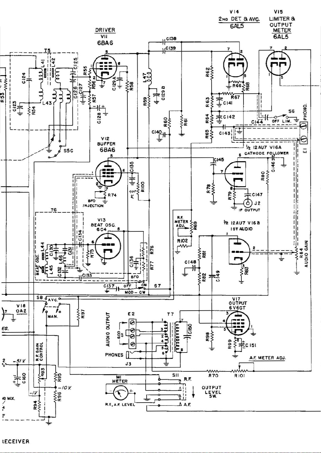
2MQ
VI'
DfT
6AL5
SAve.
VI5
UMlTERS
OUTPUT
METER
6AL5
, ,
- --_
......
5.
VI.
)1
.l.-
~
<G.
,
_51'1.
J~
+~u
Kl
MIX.
/
,
•
'-------~~
d!
"~r.-
"AN.
_.
."
cc
.
~
..
:3
cu
~
~
h
I
I
I
• I
•
~
I
r
~
•
~
-10
~
•
~
~;
~<
~
~
~
1~
~
~
0
~
~
CI!Jt-
.-
;.-
..
~
II I .
I 0
t
I
Lh.l
c.!.t.i~·
•
56
a
~O:-::L
~'
LIlli.
~
---vs
...
un!"
~
l!
·c
,
I~
I~
I
1
~
I~
I~
I
J
,
."
.2
J3
'"
i'"
'"
ow
ON
57
Ir
o ,
31
c.L
11
~
~
~
~
~
~
~
8
0
•
~
t
..
PHONES
r:
.,
METER
V.
~
I""
••.f.UYEL
..;..
I
,
,~
,
•
•
•
•
iF-
T
~
:E
I
I
-
.11
F~
Jr-
2
,~
ro
..
R.F.
--"
' I
II
II
,
"
A.F.
*
;;
~
~
N
: .
r~
•
•
~
R70
OUTPUT
LEVEL
'W.
VI7
OUTPUT
6V6GT
3
..
,-"":'-
••
.. ,
3
:~CI51
~
AF.
METER
\ I
RIO!
ADJ
•
tECEIVER
Page 30
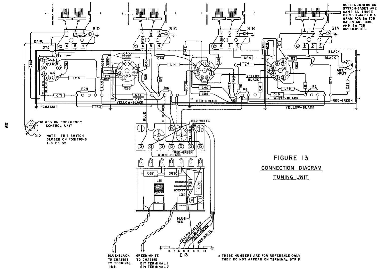
r---f-"-'
"""'''--±'I
C75
o!
JtJt:t=~S~l
B 5IA
NOTE: NUMBERS
SWITCH-IIASES
SAMEASTHOSE
ON
SCHEMATIC
GRAM
FOR
eASES
liNe
AND
SWITCH
...
SSEIoIBLIES.
ARE
DIA-
SWITCH
COIL
ON
O~
•
~
•
\CfiASSIS
~TO
~'3
~~~TORNotluE~~~l':NGT
NOTE:
CLOSEDONPOSITIONS
1~6
1..24 "
R29
-nm,-;--..,o~oi=~o;-7
.,
•
THIS
SWITCH
Of
52.
CIDI~/1,,1
I'
151
1151
1151
067',_
'"
L32V(
D
J=Gf
• 7 0
,
~
V2
. ([
• •
!!?
2.
040
C22.Q
REO-GIIEEN
,0
,"
,0
L I
'"
~BLACK
II:: R6
1:
r~!
0
CONNECTION
"
",
WHITE-IlLACK Y
YELLOW-BLACK
FIGURE
~.
13
DIAGRAM
TUNING
UNIT
":~:'lb
ANT.
INPUT
'(
REO-GREEN
IF
'/.Jk,
/'
II
~
~
BLUE-BLACK
TO
CHASSIS
T:l
TERMINAL
111011.
...P
~
GREEN·WHITE E
TO
CHASSIS
EI7
TERMIN,I,L
EI4
TERMINAL 7
BLUE·
RED
117654""'."
I
13
• THESE
NUMBERS
THEYDONOT
ARE
FOR
APPEARONTERMINAL
REfERENCE
ONLY
STRIP
Page 31
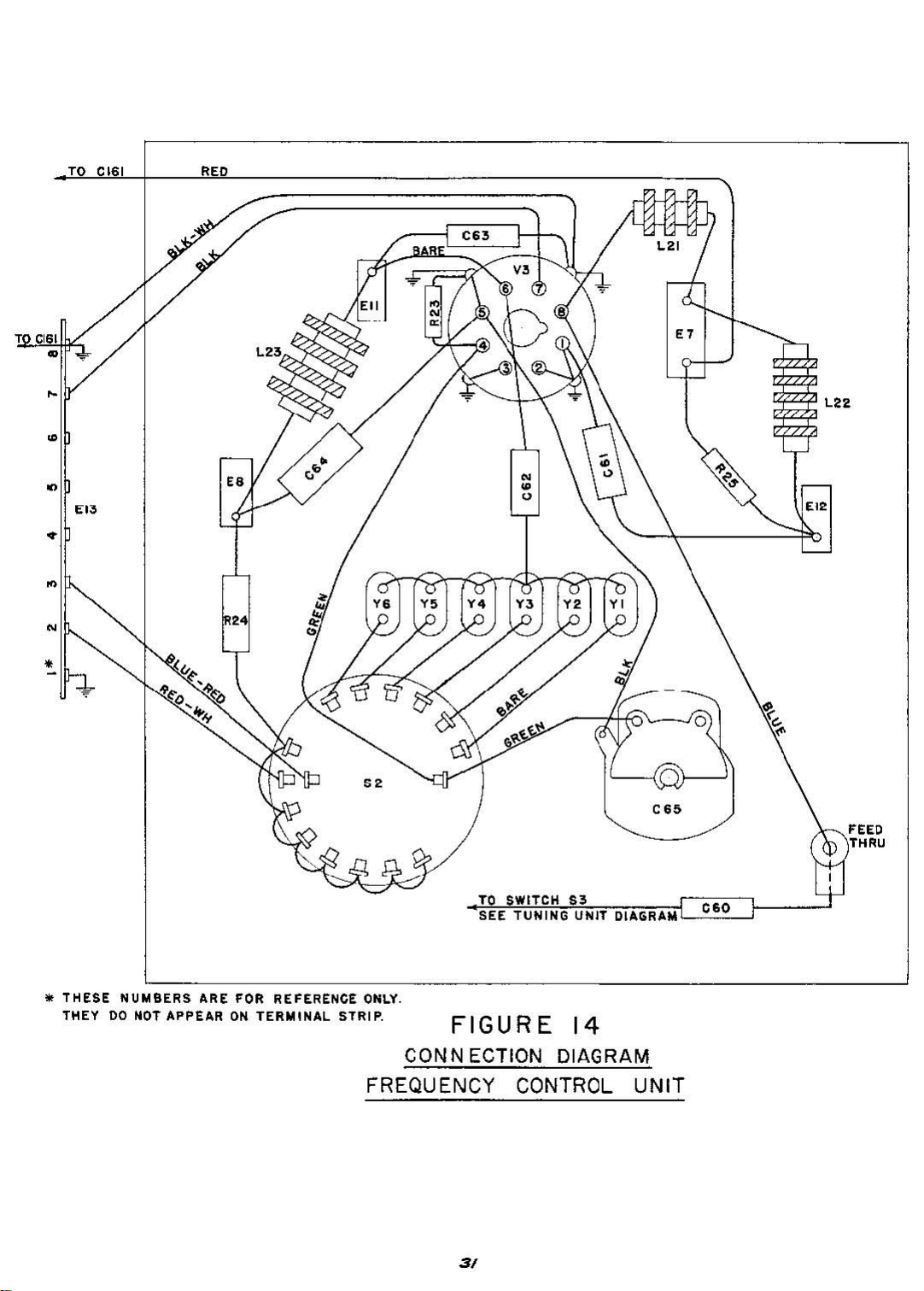
TO
CI61
T
CI61
G
REO
,
L2Z
•
G
EO>
E.
E"
•
~
N
•
-
..
•
THESE
THEY
NUMBERS
00
NOT APPEAR
ARE FOR REFERENCE
ON
TERMINAL
STRIP.
TO
ONLY.
SWITCH
SEE
TUNING
FIGURE
S3
UNIT
14
CONN [CTION DIAGRAM
FREQUENCY CONTROL
3/
DI,URAM
UNIT
060
Page 32
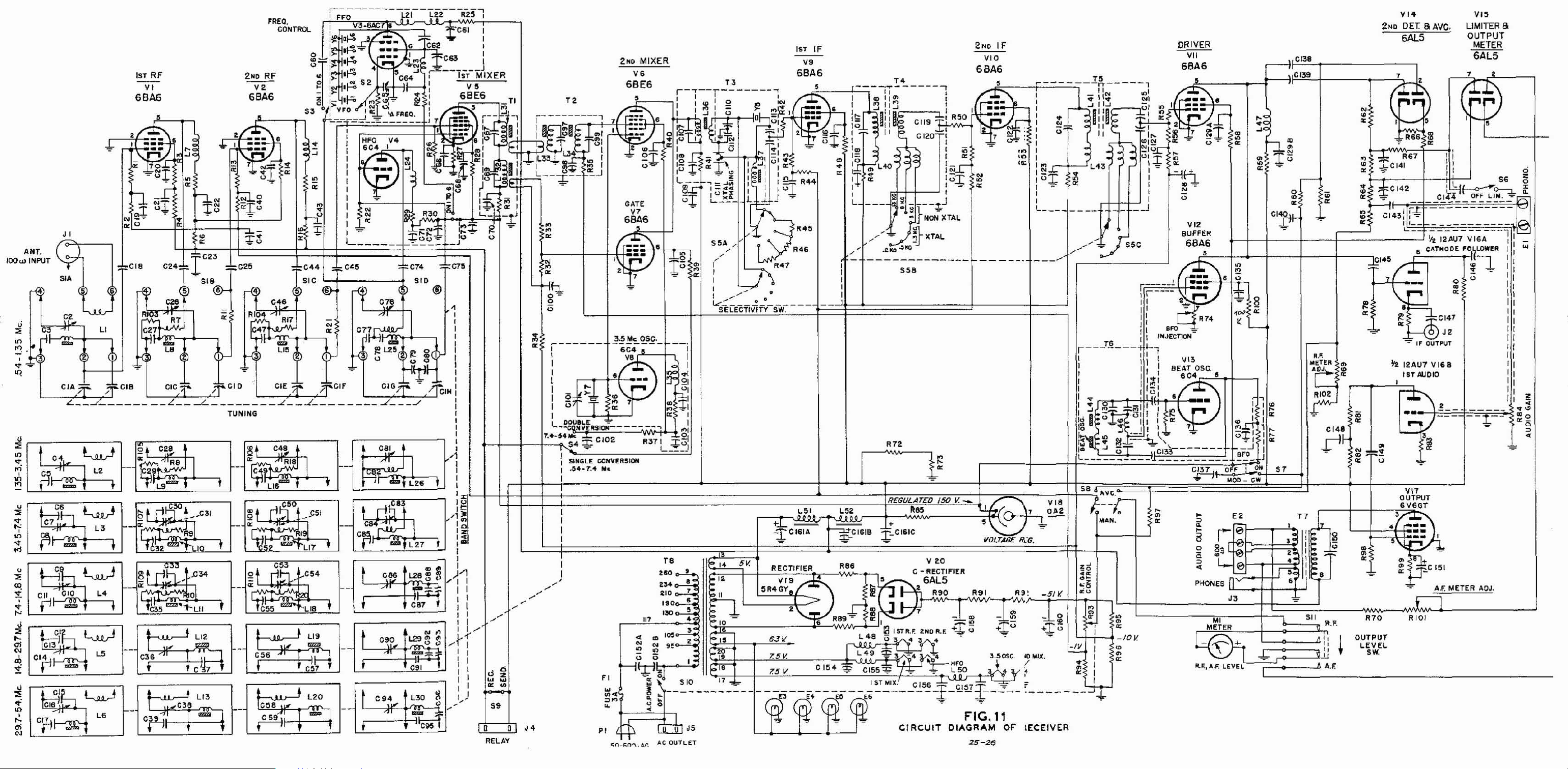
,
...
"1
C.~
C2
1ST
RF
V,
6BA6
2NO
V2
6BA6
Rf
1ST
VI4
2ND
DET a
Ave,
6AL5
If
0138
V
..
UMlTER8
OUTPUT
METER
6AL5
, ,
,
-
1;;;"10
~"'I'"'''
• 0
•
•
@
I
C•3
SIB@-
1)-
*'C
••
~
C44
SIC
fa
~
:f:
C4!5
FC74
SID
!J
C7.
(!)
o
C,.
(
(
LI
C24
C26
~"'R7
IC~!~
pr
'taa
"
..
"
,
"'
....
N
'"
'
CI.
Cl7
*i
fi
-
~
L6
! !
le58
.uJ'
C59
~'I
L'O
...
C9~
t
,
...
o;o_l;n
.....
tr.r.
AC
OUTLET
25-26
Page 33

r---j~
_
EI
,,
.-
"
J2
~~\
~
'''¥~
cb'
R69 '
BL
WHITE-BLACK
WH-GREEN
,
"
"
ACK
c
w
"
.,
CO2
" "
A
K-WHIT
REO-BLACK
'0
L.
.<
CI61
T6
~
~-----~
REO-WH
."
,
•
RE
"
®
9
"
alK
75
"
·El~
~
VI'
MAIN
o
o 0
OSCILLATOR
TERMINAL
LOCATEO
ON
WIRING
CABLE
o
NOTE:
ON
TUNING
BY
aANDSWITCH
e.~3
CL.OSED
1-2
CLOSED
o
o
o 0
REEN
BOARD
OVER
va
a
BOTTOMOFCHASSIS.
V6
BACK
fL-RED
SWITCHISMOUNTEO
UNIT
OPEftATED
BELOW
ABOVE 1,41010
O~
REO
SOCKETS
[!H~Qi.[D.J
7."
R3B
o
•
o
RB'
_____
~~"f'
L--il~
-GR
EI5
0128
0
\ V6 3
hie
CIOI
o
KT -
WHITE
,
N-
VE
LOW-R
'"
GREEN-WHITE:
FROM TUNING
UNIT.
•
,
2
,
:,
I
,=_=====~Y='''=\,~~E='
-
FIGURE NUMBER
~WHIT
BLACK-WHITE
B A
BLACI'\-WHI
====~~p,
12
7
BLUE
•
K-WHIT
,
,
•
•
"
I
•
,
~I
•
•
•
,
04
R73
•
•
,
9
;j<I
EI6
,,
•
>
•
"
•
B
i
-'==
"
'"
•
,
R A K
C109
"
•
1~~fi---/--_EI8;~
~~;i;;;;~4!'
'*
THESE
ONLY.
TERMINAL
I!.Ili.!
NUMBERS
THEY
DO
STRIP
ARE
NOT
APPEAR
<
•
~o.
~
RED-GREEN
FOR
REFERENCE
ON
59
27-28
CONNECTION DIAGRAM-RECEIVER CHASSIS
 Loading...