


1
-~-------
HQ-110A
COM'MUNICATIONS
RECEIVER
\
\
\
j
--lll
I
II
!I
I
,
-""'"
""
............
"--.
"'"
.
...
'
'
~
""',
...
...
-
~
I::
I -
I
L-
~I
TECHNICAL
DESCRIPTION
AND
OPERATING
INSTRUCTIONS
_
"",\
"-
\.
\~
\)
»
l\
,
/'
.!(
\
//
/
.'
k'
. I
Hammarlund
Manufacturing Company
A
Giannini Scientific Co.
53 West 23rd Street, New
York
10,
N.
Y.
Export Department: 13 East 40th Street, New
York
16,
N.
Y.
MANUAL
PART
NO,
41383-1
FREE DOWNLOAD
COURTESY OF N9SOR
WWW.HAMMARLUND.ORG
TIlE
HQ-IIOA
COMMUNICATIONS
RECEIVER
INSTRUCTION
AND
SERVICE
INFORMATION
FOR RECEIVERS STARTING WITH SERIAL #8900
,
ESTABLISHED
1910
ISSUE I
In
order
to
receive
the
full
unconditional
gO-day
warranty
against
defective
material
and
workmanship
in
this
receiver,
the
warranty
card
must
be
filled
out
and
mailed
within
two
weeks
of
purchase.
Please
refer
to
serial
number
of
warranty
in
correspondence.
I
,-.
THE
HAMMARLUND MANUFACTURING
CO.
A GIANNINI SCIENTIFIC
CO.
53
West 23rd Street New
York
10,
N.
Y.
FREE DOWNLOAD
COURTESY OF N9SOR
WWW.HAMMARLUND.ORG

m
Figure
J.
The HQ- JJ
OA
Communications
Receiver
TUBE
COMPLEMENT
Symbol
VI
V2
V3
V4
V5
V6
V7
V8
V9
VIO
VII
VI2
Type
6BZ6
6BE6
6BE6
I2AX7
6BA6
6AZ8
6BJ7
6AQ5
6BZ6
6C4
OB2
5U4-GB
Tube
Pentode
Pentagrid
Converter
Pentagrid
Converter
Twin
Triode
Pentode
Triode-Pentode
Triple
Diode
Pentode
Pentode
Triode
Gas
Filled
Diode
Twin
Diode
Function
RF
Amplifier
Mixer
Converter
Q-Multiplier,
First
AF
Amplifier
First
IF
Amplifier
Linear
Detector-Second
IF
Amplifier,
BFO
Detector, Noise
Limiter,
AVC
AF
Output
Crystal
Calibrator
Oscillator
HF
Oscillator
Voltage
Regulator
Rectifier
11
FREE DOWNLOAD
COURTESY OF N9SOR
WWW.HAMMARLUND.ORG
-
INTRODUCTION
The
Hammarlund
HQ-110A
is
an
all-new
amateur
communications
receiver
representing
entirely
new
concepts
in
electrical
and
mechanical
design.
It
will
provide
years
of
top
performance
with
minimum
maintenance.
The
HQ-110A
has a self-contained
power
supply
operating
from a 60
cps,
105-125
volt
AC
source.
Power
consumption
is
80
watts.
The
Hammarlund
HQ-110AC
incorporates a telechron
automatic
electric
clock-timer
in
its
design.
The
ex-
port
model,
HQ-llOAE,
now
available,
will
operate
from a 50
or
60
cps,
115-230
volt
AC
source,
5ee
Fig-
ure
13
for
Wiring
Instructions.
The
HQ-110A
is a superheterodyne
receiver
with
a
frequency
coverage
of
the
amateur
bands
as
follows:
160
meter
band,
1.8
to
2.0
mc,
calibrated
in
5
KC
divisions.
30
meter
band,
3.5
to
4.0
mc,
calibrated
in
5
KC
divisions.
40
meter
band
7.0
to
7.3
mc,
calibrated
in
5
KC
divisions
20
meter
band,
14.0
to
14.4
mc,
calibrated
in
5
KC
divisions
IS
meter
band,
21.0
to
21.6
mc,
calibrated
in
10
KC
divisions.
10
meter
band,
23.0
to
30.0
mc,
calibrated
in
20
KC
divisions.
6
meter
band,
50.0
to
54.0
mc,
calibrated
in
50
KC
divisions.
A 2
Meter
scale
is
provided
for
use
with a converter
which
has
an
output
in
the 6 meter
band.
Double
conversion
is
employed
for
the
40, 20,
IS,
10
and
6
meter
bands.
A
single
control
provides
extremely
fine
tuning
for
the
separation
of
crowded
signals. A very
high
sig-
nal-to-noise
ratio,
plus
the
famous
Hammarlund
noise
limiter
circuit,
permits
full
use
of
the
receiv-
er's
excellent
sensitivity
on
the
weakest
signal.
A
Q-Multiplier
is
provided
for
varying
the
selectivity
of
the
receiver.
A
new
audio
output
circuit
feature
is
the
Auto-Re-
sponse,
which
automatically
narrows
and
widens
the
frequency
range
of
the
audio
output,
according
to
the
gain
required.
This
feature
permits
higher
fidel·
ity
reception
on
stronger
signals,
while
providing
the
sharp
cutoff
required
in
receiving
communica-
tions
under
adverse
conditions. A second
advantage
of
the
Hammarlund
Auto-Response
is
the
rapid
damping
of
the
audio
power
in
the
speaker
voice
coil
which
greatly
minimizes
undesirable
speaker
"hangover."
The
receiver
may
be
used
with
either
speaker
or
headphones.
Fast
acting AVC
maintains
a
constant
audio
level.
Adequate
filtering
practically
eliminates
AC
power
ripple.
The
HQ-110A
is
equipped
with a stable
beat
fre-
quency
oscillator
which
provides
the
operator
with
a
continuous
range
of
audio
tones
when
receiving
telegraphic
code
signals.
When
used
in
conjunction
with
the
Q-Multiplier,
single
signal
reception
is
assured.
A 100
KC
crystal-controlled
oscillator
is
incorpor-
ated
to
provide
100
KC
check
points
for
precise
cali-
bration
on
all
seven
bands.
A
linear
detector
is
provided
for
the
optimum
re-
ception
of
55B
and
CW
signals.
An
"5"
.meter
is
provided
to
obtain
accurate
read-
ings
on
received
phone
signals
and
to
assure
"on-
the-nose"
tuning. A send-receive
switch
is
provided
to
silence
the
receiver
while
transmitting.
Large,
comfortable
controls
in
logical
groupings
are
provided
for
greatest
operating
ease.
The
new
futur-
istic
front
panel
is
clearly
marked
to
permit
full
at-
tention
to
the
operation
at
hand.
The
HQ-110A
was
designed
with
you
in
mind. You'II
have
many
hours
of
pleasure
and
use
in
operating
this
truly
fine
communications
instrument.
1
FREE DOWNLOAD
COURTESY OF N9SOR
WWW.HAMMARLUND.ORG
In
~
75FT
OVERALL--
RECEIVER
A
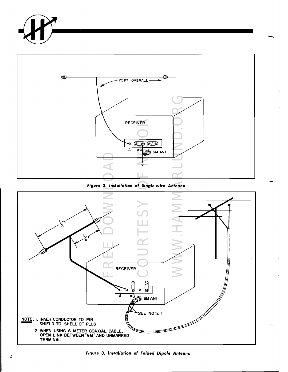
Figure 2. Installation
of
Single-wire
Antenna
NOTE: I.
INNER
CONDUCTOR
TO
PIN
= SHIELD
TO
SHELL
OF
PWG
2.
WHEN
USING
6 METER COAXIAL CABLE,
OPEN
LINK BETWEEN
"6M"
AND
UNMARKED
TERMINAL.
Figure
3.
Installation
of
Folded Dipole
Antenna
2
FREE DOWNLOAD
COURTESY OF N9SOR
WWW.HAMMARLUND.ORG
------------0
INSTALLATION
UNPACKING
Unpack
the
receiver
carefully.
Make
sure
the
tubes,
associated
tube
shields
and
pilot
lamps
are
in
place.
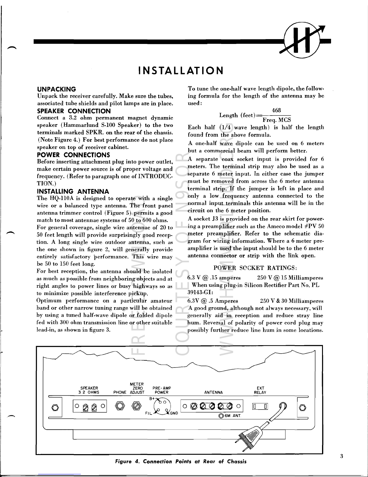
SPEAKER
CONNECTION
Connect
a 3.2
ohm
permanent
magnet
dynamic
speaker
(Hammarlund
S-100
Speaker)
to
the
two
terminals
marked
SPKR.
on
the
rear
of
the
chassis.
(Note
Figure
4.)
For
best
performance
do
not
place
speaker
on
top
of
receiver
cabinet.
POWER CONNECTIONS
Before
inserting
attachment
plug
into
power
outlet,
make
certain
power
source
is
of
proper
voltage
and
frequency.
(Refer
to
paragraph
one
of
INTRODUC-
TION.)
INSTALLING ANTENNA
-
The
HQ-IIOA
is
designed
to
operate
with a single
wire
or a balanced
type
antenna.
The
front
panel
antenna
trimmer
control
(Figure
5)
permits a good
match
to
most
antennae
systems
of
50
to
600
ohms.
For
general
coverage,
single
wire
antennae
of
20
to
50
feet
length
will
provide
surprisingly
good
recep-
tion. A long
single
wire
outdoor
antenna,
such
as
the
one
shown
in
figure
2,
will
generally
provide
entirely
satisfactory
performance.
This
wire
may
be
50
to
150
feet
long.
For
best
reception,
the
antenna
should
be
isolated
as
much
as
possible
from
neighboring
objects
and
at
right
angles
to
power
lines
or
busy
highways
so as
to
minimize
possible
interference
pickup.
Optimum
performance
on a particular
amateur
band
or
other
narrow
tuning
range
will
be
obtained
by
using a tuned
half-wave
dipole
or
folded
dipole
fed
with
300
ohm
transmission
line
or
other
suitable
lead-in,
as
shown
in
figure
3.
To
tune
the
one-half
wave
length
dipole,
the
follow-
ing
formula
for
the
length
of
the
antenna
may
be
used:
468
Length
(feet)
Freq.
MCS
Each
half (1/4
wave
length)
is
half
the
length
found
from
the
above
formula.
A
one-half
wave
dipole
can
be
used
on 6 meters
but a commercial
beam
will
perform
better.
A
separate
coax
socket
input
is
provided
for
6
meters.
The
terminal
strip
may
also
be
used
as a
separate 6 meter
input.
In
either
case
the
jumper
must
be
removed
from
across
the 6 meter
antenna
terminal
strip.
If
the
jumper
is
left
in
place
and
only a low
frequency
antenna
connected
to
the
normal
input
terminals
this antenna
will
be
in
the
circuit
on
the 6 meter
position.
A
socket
J3
is
provided
on
the
rear
skirt
for
power-
ing a preamplifier
such
as
the
Ameco
model
#PV
50
meter
preamplifier.
Refer
to
the
schematic
dia-
gram
for
wiring
information.
Where
a 6
meter
pre-
amplifier
is
used
the
input
should
be
to
the 6 meter
antenna
connector
or
strip
with
the
link
open.
POWER
SOCKET
RATINGS:
6.3 V @ .15
amperes
250 V @ 15
Milliamperes
When
using
plug-in
Silicon
Rectifier
Part
No.
PL
39143-GI:
6.3V
@
.5
Amperes
250 V & 30
Milliamperes
A
good
ground,
although
not
always
necessary,
will
generally
aid
in
reception
and
reduce
stray
line
hum.
Reversal
of
polarity
of
power
cord
plug
may
possibly
further
reduce
line
hum
in
some
locations.
,...-..
o
SPEAKER
32
OHMS PHONE
METER
ZERO
ADJUST
PRE - AMP
POWER
ANTENNA
EXT
RELAY
o
3
Figure
4.
Connection Points
at
Rear
of
Chassis
FREE DOWNLOAD
COURTESY OF N9SOR
WWW.HAMMARLUND.ORG

I
1-1
1
2
13--"';"'---
12
---~---!!i!.o=:!
!!::!::::i!+--
3
INDEX
NO.
2
3
4
5
6
7
11
10
CONTROL
CAL
SET
Control
"s"
Meter
(Carrier
Level)
FREQ.
Control (Q-MultipIier)
SELECTIVITY
Control (Q-MultipIier)
FUNCTION
Switch
AUDIO
GAIN
Control
LIM
Switch (Noise
Limiter)
9 8
INDEX
NO.
8
9
10
11
12
13
14
7
6 5
CONTROL
TUNING
RANGE
Switch
(Band
Selector)
MAN-AVC Switch
SENSITIVITY
Control
TUNING
Control
ANTENNA Trimmer
CW
PITCH
Control
(Beat
Frequency
Oscilla-
tor)
Telechron
Automatic
Clock
(Timer)
Figure
5.
Location
of
Controls
4
FREE DOWNLOAD
COURTESY OF N9SOR
WWW.HAMMARLUND.ORG

OPERATION
AM
RECEPTION
For
AM
reception
the
position
of
the
controls
should
be
as
follows:
FUNCTION
Switch
_._
Receive
(REC)
TUNING
RANGE
Switch
.. ..5et
to
desired
frequency
range
MAN
- A
VC
Switch
__
_ AVC
FREQ.
Control
_
Set
pointer
to
triangular
marker
CAL
SET
Control
.Set
to
vertical
marker
LIM
Switch
_
As
required
TUNING
Control
_
Tune
for
highest
"s"
meter
reading
on
signal
ANTENNA
Trimmer
Tune
for
highest
"s"
meter
reading
on
signal
SELECTIVITY
Control
Fully
counter-
clockwise*
SENSITIVITY
Control
._
Fully
clockwise**
AUDIO
GAIN
Control
_._
Adjust
for
required
level***
*Normally
for
AM
reception,
the
Q-Multiplier
is
switched
OFF
(fully
counterclockwise)
for
maximum
bandwidth.
However,
the
Q-Multi-
plier
may
be
useful
in
eliminating
interference
from
closely
adjacent
signals
at
some
sacrifice
in
the
fidelity.
The
bandwidth
is
narrowed
by
clockwise
rotation
of
the
SELECTIVITY
con-
trol
**For
normal
AM
reception,
the
SENSITIVITY
control
is
fully
clockwise.
The
"s"
meter
calibra-
tion
holds
only
in
this
position
on AVC
opera-
tion.
In
the
presence
of
extremely
strong
signals,
the
SENSITIVITY
control
may
be
reduced
to
prevent
overloading.
***A feature
of
the
audio
system
is
the
variable
negative
feedback
employed.
Maximum
feed-
back
is
provided
at
low
settings
of
the
AUDIO
GAIN
control
for
the
best
quality
reception
of
strong
signals. As
the
AUDIO
GAIN
control
is
increased,
the
feedback
decreases
so
that
on
re-
ception
of
weak
signals
additional
selectivity
is
provided
by
the
audio
system.
This
results
in
an
increased
signal-to-noise
ratio. A further
advan-
tage
is
the
critical
damping
of
the
speaker
for
elimination
of
speaker
"hangover."
This
up-
grades
the
reception
of
speech
and
decreases
the
noise
output
of
the
receiver. A further
advantage
is
the
reduction
of
distortion
at
low
settings
of
the
AUDIO
GAIN
control.
CODE
SIGNAL
RECEPTION
For
CW
code
reception
the
position
of
the
controls
should
be
as
follows:
FUNCTION
Switch
__
_CW-SSB
TUNING
RANGE
Switch
_Set
to
desired
frequency
range
MAN
- A
VC
Switch
_
MAN
FREQ.
Control
_
Set
pointer
to
triangular
marker*
CAL
SET
Control
5et
to
vertical
marker
CW
PITCH
Control
__
Pointer
on
tri-
angular
marker
for
zero
beat
tuning
and
then
offset
either
left
or
right
for
desired
pitch
TUNING
Control
__
Tune
for
zero
beat
ANTENNA
Trimmer
..
.....
_Tune
for
maximum
response
SELECTIVITY
Control
"ON"
and
advanced
as
required
**
SENSITIVITY
Control
Adjust
for
desired
output
level
AUDIO
GAIN
Control
_
Clockwise
to
12
or
2
o'clock
position
*The
FREQ.
control
will
peak
the
selectivity
curve
to
the
left
or
right
over
the
pass
band
of
the
IF
amplifier
permitting a high
degree
of
the
control
of
selectivity
for
closely
adjacent
interfering
signals.
**The
broadest
position
of
the
SELECTIVITY
control
(corresponding
to
a 6
db
bandpass
of
3
KCS)
is
with
the
control
turned
clockwise
just
sufficiently
to
operate
its
switch.
This
puts
the
Q-Multiplier
in
operation.
Further
clockwise
rotation
of
the
control
narrows
the
bandwidth
until a position
is
reached,
just
short
of
oscilla-
tion,
where
the
bandwidth
is
of
the
order
of
100
cycles.
The
control
should
be
adjusted
below
the
point
of
oscillation
and
to
the
desired
band-
width
as
required
by
interference.
SSB
RECEPTION
For
SSB
reception
the
position
of
the
controls
should
be
as follows:
FUNCTION
Switch
_ _ CW-SSB
TUNING
RANGE
Switch
_.5et
to
desired
frequency
range
MAN-A
VC
Switch
_ __.MAN
FREQ.
Control
__
Set
pointer
to
triangular
marker
CAL
SET
Control
Set
to
vertical
marker
5
FREE DOWNLOAD
COURTESY OF N9SOR
WWW.HAMMARLUND.ORG

IIi
TUNING
Control
Tune
for
maximum
clarity
ANTENNA
Trimmer
.Tune
for
maximum
response
SELECTIVITY
Control
_
"ON"
but
not
advanced
beyond
switch
*
SENSITIVITY
Control
_
As
required
**
AUDIO
GAIN
Control
Clockwise
to
12
or
2
o'clock
position
****
CW
PITCH
Control
_
Approximately
1
division
left
or
right****
*The
SELECTIVITY
control
should
only
be
advanced
beyond
the
switch
"ON"
position
if
required
to
increase
the
selectivity
due
to
interference.
**The
SENSITIVITY
control
should
be
advanced
only
sufficiently
to
provide
the
required
output.
The
use
of a minimum
SENSITIVITY
control
setting
insures
that
no
overload
distortion
oc-
curs
in
the
receiver.
***Operating
with
the
AUDIO
GAIN
control
advanced
1/2
to
2/3
rotation
insures
sufficient
power
output
while
permitting
the
reduced
SENSITIVITY
operation
described
above.
****The
CW
PITCH
control
is
set
approximately
1
division
to
the
right
or
left
of
the
triangular
marker,
depending
on
whether
the
upper
or
the
lower
side
band,
respectively,
is
transmitted.
The
CW
PITCH
control
is
adjusted
for
maxi-
mum
clarity,
once
the
signal
has
been
tuned
in.
There
will
be a correct
setting
of
this
control
for
each
sideband
and
once
these
two
settings
are
determined,
they
should
be
noted
for
future
use
in
SSB
reception.
CALIBRATE
For
dial
calibration
checking,
the
FUNCTION
switch
is
set
at
the
CAL
position
and
the
other
COH-
troIs
should
be
set
as
listed
under
CODE
SIGNAL
RECEPTION.
The
receiver
is
aligned
with
the
CAL
SET
control
set
at
the
vertical
marker
and
should
be
closely
correct.
The
CAL
SET
control
is
used
to
accurately
reset
the
dial
indicator
lines
if
they
are
found
to
be
slightly
off
calibration
at
any
point
on
the
dials
where
correct
calibration
is
desired.
The
receiver
is
tuned
to
produce a zero
beat
response
with
the
PITCH
control
set
at
the
triangular
marker,
on
any
100
KCS
multiple
in
the
desired
band.
The
CAL
SET
control
is
then
used
to
reset
the
dial
indicator
to
the
correct
marker.
If
the
dial
calibration
should
be
foun-d
to
be
beyond
the
range
of
the
CAL
SET
control,
the
HF
Oscillator
will
re-
quire
readjustment
(see
under
SERVICE
AND
RE-
ALIGNMENT)
.
On
switching
from
the
CW-SSB
position
to
the
CAL
position,
an
increase
in
level
will
be
noticed.
This
is
done
deliberately
to
provide
additional
gain
for
the
higher-order
harmonics
of
the
100
KCS
crystal
calibrator,
regardless
of
whether
the
receiver
is
in
MAN
or AVC
position.
Note
As
only
the
amateur
bands
are
covered
by
this
receiver
it
is
not
possible
to
compare
the
100
KCS
freq.
calibrator
against
WWV.
The
100
KCS
crystal-controlled
oscillator
has
been
accurately
set
at
the
factory.
This,
plus
the
fact
that a very
low
drift
.005%
crystal
is
employed,
will
insure
sufficient
accuracy
for
all
practical
purposes.
For
those
who
desire
frequency
ac-
curacy
of
the
crystal
calibrator
in
the
order
of
cycles,
the
procedure
outlined
on
Page
14
should
be
employed.
EXTERNAL
RELAY
CONNECTION
A
standard
power
receptable
is
provided
on
the
rear
apron
of
the
chassis
for
the
connection
of
an
ex-
ternal
relay-operated
switch.
This
receptacle
accom-
modates a standard
power
plug
and
when
so
used
the
SEND
position
of
the
FUNCTION
SWITCH
is
not
used.
A
jump~r
plug,
provided
for
normal
without
relay
switching,
is
removed
from
the
recep-
tacle
when
using
the
relay
switching.
The
usual
antenna
change-over
relay
equipped
with
a
set
of
normally
closed
contacts
is
suggested.
The
choice
of
this
relay
will
depend
on
the
particular
antenna
system
involved,
such
as
whether
a co-ax
relay
or
one
for
open
wire
line
is
employed.
In
either
case
the
extra
set
of
contacts
to
control
the
receiver
will
be
necessary.
TELECHRON
AUTOMATIC
CLOCK-TIMER
If
your
receiver
is
equipped
with
the
built-in
Tele-
chron
Automatic
Clock-Timer,
the
following
in-
structions
should
be
noted:
Every
radio-frequency
device
is
stable
only
at
pre-
determined
operating
temperatures.
In
order
to
eliminate
waiting
for
the
receiver
to
warmup
to
operating
temperature,
the
Telechron
Timer
auto-
matically
turns
on
the
receiver
ahead
of
anticipated
operating
time.
This
is
accomplished
by
setting
the
6
FREE DOWNLOAD
COURTESY OF N9SOR
WWW.HAMMARLUND.ORG

--
hand
of
the
timer
(small
knob
at
rear
of
receiver)
to
approximately
one-half
hour
before
operating
time.
The
front
panel
control
under
Timer
is
then
set
to
"Auto"
position.
The
function
switch
is
set
to
REC.
The
receiver
is
then
automatically
turned
on
at
the
desired
time.
The
clock
hands
are
set
by
the
rear
knob.
"Push
in"
and
turn
the
knob
to
set
the
switch
timing
hand
and
"pull
out"
and
turn
the
knob
to
set
the
clock
hands.
The
front
switch
is
set
to
AUTO
and
the
function
switch
is
set
to
REC.
when
it
is
desired
to
use
the
automatic
clock
switch
for
pre-warming
the
receiver
before
operation
or
for
use
as
an
alarm
to
turn
the
receiver
on
to a pre-tuned
station.
To
use
the
function
switch
normally,
the
clock
switch
should
be
left
in
the
ON
position.
The
clock
will
continue
to
run
as
long
as
the
re-
ceiver
line
cord
is
connected
to
the
power
outlet,
and
is
extremely
useful
for
checking
sign-in
periods
and
schedules.
If
your
receiver
is
not
equipped
with
the
standard
Telechron
Automatic
Clock-Timer,
and
you
would
care
to
have
the
accessory
added,
The
Clock
Kit,
with
full
installation
instructions,
may
be
pur-
chased
from
your
local
Hammarlund
dealer.
Instructions
for
connecting
the
standard
clock·timer
are
as
indicated
in
figure
12.
The
Export
Model
Clock-Timer
HQ-110AE
is
now
available
from
your
local
Hammarlund
Dealer.
This
automatic
Clock-Timer
will
operate
from
a 50-60
CPS,
115-230
Volt
AC
source.
Instructions
for
con-
necting
the
export
model
Clock-Timer
are
as
indi-
cated
in
Figure
13.
CIRCUIT THEORY
The
HQ-110A is a
superheterodyne
receiver
cover-
ing
the
6, 10, 15, 20, 40,
80.and
160
meter
amateur
frequency
bands.
Double
conversion
is
employed
in
the 6 through
40
meter
bands.
Twelve
tubes
are
used,
including
the
Rectifier
and
Voltage
Regulator
of
the
self-contained
power
supply.
The
circuitry
of
the
receiver
includes
a 100
KCS
crystal
calibrator,
a
Q-Multiplier
for
full
control
of
selectivity,
an
effec-
tive
noise
limiter
and a separate
highly
stable
Beat
Frequency
Oscillator.
PRESELECTION
The
antenna
input
coupling
and
RF
amplifier
stage
provide
the
necessary
preselection
and
gain
for
high
performance
and
rejection
of
undesired
signals.
The
high
signal
level
at
the
mixer
grid,
V2,
contributes
to a favorable
signal-to-noise
ratio.
Both
grid
and
plate
circuits
of
the
RF
stage
are
tuned;
individual
tuning
coils
are
selected
for
each
band.
The
antenna
compensating
capacitor,
adjustable
from
the
front
panel,
permits
the
receiver
to
be
resonated
for
optimum
performance
with
the
par-
ticular
antenna
in
use.
CONVERTER
STAGE
A
high
degree
of
oscillator
stability
is
attained
by
the
use
of a separate
mixer
(6BE6),
V2,
and
an
in-
dependent
oscillator
(6C4),
VI0.
The
output
signal
from
RF
amplifier,
VI,
is
hetero-
dyned
with
the
output
of
the
local
high
frequency
oscillator,
VlO,
and
electronically
combined
within
the
mixer
tube,
V2.
On
the
80
and
160
meter
bands,
the
local
oscillator
is 455
KCS
above
the
signal
frequency.
On
the
10
to
40
meter
bands,
the
local
HF
Oscillator
is 3035
KCS
above
the
signal
fre-
quency.
On
the
6'meter
band,
the
local
HF
Oscilla-
tor
is 3035
KCS
below
the
signal
frequency.
When
operating
in
the 6 to
40
meter
bands,
the
dif-
ference
frequency
of
3035
KCS
is
heterodyned
with
the
output
of
the
2580
KCS
crystal
controlled
oscil-
lator
and
electronically
combined
within
the
con-
verter
tube,
V3,
to
produce
the
455
KCS
final
inter-
mediate
frequency.
Low-loss
tube
sockets,
low-loss
phenolic,
temperature
compensating
capacitors,
and
stable,
coaxial
glass
trimmer
all
contribute
to
oscillator
stability.
Addi-
tional
frequency
stability
is
attained
by
applying
regulated
voltage
to
the
oscillator
circuit
and
by
the
rugged
construction
of
the
entire
HF
oscillator
sec-
tion
assembly.
Q·MULTIPLIER
The
Q-Multiplier
circuit
employed
in
this
receiver
provides a means
of
peaking
any
signal
within
the
pass
band
of
the
IF
amplifier.
The
degree
of
peak-
ing
is
controlled
by
the
SELECTIVITY
control.
The
bandwidth
varies
from 3 KCS
with
the
SELECTIV.
ITY
control
switch
just
"ON"
to
approximately
100
7
FREE DOWNLOAD
COURTESY OF N9SOR
WWW.HAMMARLUND.ORG
cps
with
the
control
just
below
the
oscillation
point.
If
interference
is
experienced
caused
by
two
stations
operating
very
close
to
one
another,
the
Q-Multi-
plier
may
be
employed
under
these
circumstances
to
minimize,
if
not
eliminate,
the
interference
by
the
improved
selectivity
or'
the
decreased
bandwidth
proper
adjustment
will
provide.
The
proper
use
of
the
Q-Multiplier
can
actually
enhance
many
times
the
results
obtained
with
the
receiver.
In
view
of
this,
it
is
suggested
that a little
time
be
spent
in
learning
just
how
to
properly
adjust
the
Q-Multi-
plier
frequency
and
selectivity
controls
under
differ·
ent
receiving
conditions.
As
the
Q.Multiplier
SELECTIVITY
control
is
advanced, a decided
de-
crease
in
noise
will
be
apparent.
This
is
due
to
the
narrowing of
the
pass
band.
On
AM
pbone
signals
this
control
will
usually
be
between
the 7 and
II
o'clock
positions.
The
FREQUENCY
control
should
then
be
adjusted
for
clarity
of
signal
or
for
minimum
adjacent
channel
interference.
The
SELECTIVITY
control
may
be
advanced
progres-
sively
more
for
SSB
and
CW
reception.
The
more
this
control
is
advanced,
the
more
critical
the
set-
ting
of
the
FREQUENCY
control
becomes.
The
CW
PITCH
control
will
also affect
the
Q-Multiplier
FREQUENCY
control
setting.
Advancing
the
SELECTIVITY
control
too
far
will
cause
the
Q-
Multiplier
to
oscillate.
This
should
be
avoided
and
the
best
setting
of
this
control
for
CW
reception
is
just
below
the
oscillation
point,
where
maximum
peaking
occurs.
The
Q-Multiplier
is a
very
handy
tool
in
the
hands
of
an
experienced
operator
and,
unfortunately,
it
is
beyond
the
scope
of
this
instruc.
tion
manual
to
attempt
to
be
more
definite
than
we
have.
IF
AMPLIFIER
Nine
stable
tuned
circuits,
in
three
stages
of
IF
am-
plification,
V3, V5,
and
V6A,
contribute
to
sensi-
tivity
and
selectivity.
On
the
80
and
160
meter
bands,
the
Intermediate
frequency
is 455 KCS.
On
the 6 to
40
meter
bands,
the
first
conversion
is
to
an
Intermediate
frequency
of
3035 KCS,
employing
two
tuned
circuits
and
the
second
conversion
is
to
the
455
KCS
Intermediate
frequency
employing
seven
tuned
circuits.
Iron
core
permeability-tuned
transformers
improve
performance
and
add
to
the
ease
of
adjustment.
AVC
SYSTEM
Automatic
Volume
Control
minimizes
fading
and
signal
strength
variations
by
controlling
the
gain
of
the
RF
stage,
VI,
and
the
IF
stage, V5. As a
result,
a
comfortable
and
constant
level
of
audio
is
main-
tained.
The AVC
voltage
for
the
RF
Amplifier
tube,
VI,
is
provided
with a delay
voltage
which
prevents
the
AVC
from
operating
on
the
RF
Amplifier
tube
on
extremely
weak
signals,
thus
maintaining
the
maximum
sensitivity
and
signal-to-noise
ratio.
"5"
METER
(CARRIER
LEVEL)
The
"S",
or
Tuning,
Meter
is
provided
to
assist
in
tuning
and
to
give
an
indication
of
relative
signal
strength.
Because
the
meter
readings
are
propor-
tional
to
AVC voltage,
it
is
operative
only
in
the
AVC
position
and
on
AM
reception.
In
the
MAN
position
of
the
MAN-A
VC
switch,
the
meter
pointer
will
not
indicate
the
signal
strength.
However,
the
meter
pointer
will
assume
various
positions,
includ.
ing
slightly
off scale,
depending
on
the
setting
of
the
SENSITIVITY
control
and
the
FUNCTION
switch.
In
any
operating
position
of
the
FUNCTION
switch,
receiver
overload
is
indicated
by a reverse
reading
of
the
meter.
The
meter,
which
is
calibrated
to
40
db
over
S-9, is
factory
adjusted
so
that a signal
input
of
approxi-
mately
50
microvolts
gives a
reading
of
S-9.
Each
"s"
unit
indicates
a 6
db
increase,
equivalent
to
doubling
signal
strength.
Should
meter
readjust-
ment
be
necessary:
1.
Set
FUNCTION
switch
to
REC.
2.
Set
front
panel
SENSITIVITY
control
to
"10."
3.
With
receiver
off,
mechanically
zero
pointer
with
a fine
screwdriver.
4.
With
AVC
on
and
the
ANT.
terminals
shorted,
adjust
the
pointer
to
zero
with
ZERO
AD}
potentiometer
R19.
DETECTOR
AND
NOISE
LIMITER
One
section
of
the
6BJ7
tube,
V7, is
used
for
the
sec-
ond
detector
and
AVC
system
for
the
IF
amplifier.
This
system
produces a minimum
of
distortion.
8
FREE DOWNLOAD
COURTESY OF N9SOR
WWW.HAMMARLUND.ORG

+4
+2
0
-2
-4
..
-6
.!
u
>.
-9
(,)
0
0
-10
0
-
E
-12
0
~
tIl
-14
a
-16
-18
-20
-22
10
~1
I-Ill~
~
I:
~.
~
....
.,~
IIIl
_.
~
,..
,
,~
~
"'IIIl
"
,
L
..
/
,
,
.......
~
.#
"
,
~
4
~
I~~
~
•
,
II....
~r
HQ-llOA
Audio
Characteristic
.,~
A--Max.
AF
Gain
Control
If
IJ
B ---
AF
Gain
Approx.
25%
of
rotation
I~
from
Min.
Simulating
Average
J
Setting
for
local
Broadcast
~
Stations
(IV
at
Antenna
Input)
Output
at
1000
CPS = 500
MW
,
A
Input
.10 V Across
AF
Gain
Control
Con-
~
stant
J
B
Input
1.4 V Across
AF
GAIN
Control
Con-
I'.
stant
If
A
10
1
10
3
Frequency
in
Cycles
Per
Second
Figure 6.
Auto-Response
Curve
One
section
of
the
V7
operates
as a series,
self·ad·
justing
noise
limiter.
It
will
reduce
automobile
ig-
nition
and
other
types
of
impulse
noise
to a minimum.
Intelligibility
is
not
affected
by
the
noise
limiter,
although
it
may
be
switched
off
if
desired.
The
third
section
of
the
V7
provides
delayed AVC
for
tbe
RF
amplifier
tube.
BEAT
FREQUENCY
OSCILLATOR
(BFO)
The
triode
section
of
the
(6AZ8) V6B is
used
for
the
beat
frequency
oscillator.
The
CW
PITCH
con·
trol
is
used
to
vary
the
beat
tone.
Each
calibration
division
of
this
control
represents
approximately
1000 cycles.
When
receiving
single
side
band
trans-
mission,
the
generally
accepted
procedure
of
setting
the
beat
frequency
oscillator
approximately
2000
cycles
above
or
below
zero
beat
should
be
employed.
In
other
words,
if
the
beat
frequency
oscillator
CW
PITCH
control
is
set
two
degrees
clockwise
or
coun-
terclockwise
from
the
center
position,
optimum
single
side
band
reception
will
usually
be
obtained.
Whether
the
beat
frequency
oscillator
control
will
be
set
clockwise
from
zero
beat
will
depend
on
whether
upper
or
lower
side
band
is
being
trans-
mitted.
If
the
beat
frequency
oscillator
is
on
the
wrong
side
of
zero
beat,
it
will
be
impossible
to
obtain
intelligibility
of
the
single
side
band
signal
when
the
dial
is
tuned
very
slowly
through
the
single
side
band
signal.
Should
such a condition
arise,
merely
rotate
the
CW
PITCH
control
from
the
two
degrees
counterclockwise
to
the
two
degrees
clockwise
position
and
then
very
carefully
adjust
the
tuning
for
intelligible
speech.
Here
again
ex-
perience
is
the
best
teacher.
The
stability
of
both
the
high
frequency
oscillator
employed
in
this
receiver
plus
the
excellent
mechanical
rigidity
will
provide
excellent
single
side
band
reception.
Refer
to
the
above
paragraph
on
the
Q-Multiplier
for
im-
proved
single
side
band
reception.
CRYSTAL
CALIBRATOR
A
(6BZ6)
tube,
V9, a
hermetically
sealed
quartz
crystal
unit
and
associated
components,
provide
a
highly
stable
100
KC
crystal-controlled
oscillator.
9
FREE DOWNLOAD
COURTESY OF N9SOR
WWW.HAMMARLUND.ORG

An
adjustable
ceramic
trimmer
capacitor
is
pro-
vided
for
accurately
adjusting
the
oscillator
fre-
quency
against
an
external
standard
frequency
such
as
WWV.
It
provides
signal
markers
at
100
KC
in-
tervals
throughout
the
tuning
range
of
the
receiver.
I.INEAR
DETECTOR
The
pentode
section
of
the
(6AZ8)
V6A
functions
as a
linear
detector
for
CW
and
SSB
reception,
re-
sulting
in a clear
undistorted
beat
note
on
CW
and
greater
ease
of
tuning
and
freedom
from
interfer-
ence
on
SSB
reception.
AUDIO
AMPLIFIER
The
first
audio
stage
is a
resistance
coupled
voltage
amplifier
employing
the
other
section
of
the
(I2AX7)
V4B.
The
audio
output
stage
is a
(6AQ5)
beam
power
amplifier,
V8,
providing
an
undistorted
output
level
of
at
least
one
watt.
SUGGESTED
PROCEDURE
FOR
EI.IMINATING
COMMON
TROUBLES
1.
Most
of
the
trouble
that
has
developed
has
been
due
to
one
or
more
defective
tubes.
In
the
event
your
receiver
has
excessive
hum
or
erratic
"S"
meter
operation,
the
two
tuhes
most
likely
to
cause
this
condition
is V7
in
the
schematic
dia-
gram
on
Page
19
of
our
Instruction
Manual,
this
is a
6Bj7
or
V6A,
the
6AZ8
tube
type
may
also
develop
internal
shorts.
2.
Failure
of
the
"Q"
multiplier
to
operate
prop-
erly
or
another
possible
source
of
excessive
hum
may
be
due
entirely
to
the
12AX7,
V4A
and
V4B,
since
this
is a
combined
"Q"
multiplier
tube
and
first
audio
amplifier.
Please
do
not
rely
too
much
on
testing
the
tubes
in a tube
tester
unless
they
are
completely
dead,
when
internal
shorting
occurs,
there
is a
possibility
that a tube
tester
will
not
prove
reliable.
This
is
due
to
the
fact
that
most
tube
testers
do
not
pro-
vide a means
of
testing
excessive
heater
to
cath-
ode
leakage,
which
is
the
most
common
cause
of
hum
complaints.
It
is
therefore,
suggested
that
any
suspicious
tube
be
replaced
with a new
one,
sinc~
this
is
by
far
the
best
method
of
defi.
nitely
eliminating
this
possible
cause
of
com·
plaint.
3.
Excessive
oscillator
drift
which
would
be
most
noticeable
on
all
of
the
high
frequency
bands
plus a microphonic
condition
is
usually
the
re-
sult
of a poor
type
6C4
high
frequency
oscillator
or
VI0
in
the
schematic
diagram.
This
tube
is
also
capable
of
producing a poor
beat
note
that
may
have a ripple
in
it,
especially
noticeable
on
the
high
frequency
bands.
4.
Excessive
drift
can
also
be
attributed
to a poor
6BE6
employed
in
position
V2.
In
addition,
the
6BE6
employed
in
V2
can
also
cause
hum
modu-
lation
which
will
be
most
noticeable
on
the
two
high
frequency
band~.
Sometimes
merely
inter-
changing
the 2 6BE6
tubes
employed
in
Posi-
tions
V2
and
V3
may
produce a noticeable
im-
provement.
If
this
is
not
the
case,
we
would
sug-
gest
the
purchase
of
another
6BE6.
5.
It
is
normal
for
less
output
to
be
obtained
in
the
CW
ISSB
position
than
in
the
Receive
or
Cali-
brate
position.
To
compensate
for
the
slight
loss
in
level,
merely
advance
the
audio
control
should
this
be
required.
CALI
BRA
TION COMPLAINTS:
Please
remember
that
the
100
kc
calibrator
was
built
into
the
HQ-IIOA
receiver
as a
means
of
de-
tecting
dial
error.
The
incorporation
of
the
100
kc
crystal
oscillator
does
not
mean
that
you
will
find
the
100
kc
markers
exactly
at
100
kc
intervals,
inso-
far
as
dial
reading
are
concerned.
Obviously,
if
the
100
kc
calibrator
would
line
up
at
each
of
the
100
kc
dial
markers,
there
would
be
no
point
in
incor-
porating
the
100
kc
crystal
calibrator.
Dial
error
in
the
order
of 5 to
10
kc
for
the
lower
frequency
bands,
and
25
to
50
kc
error
on
the
10
and 6 meter
bands,
is
within
our
production
tolerance.
The
pro-
cedure
for
correcting
frequency
deviations
in
excess
of
those
previously
specified
will
usually
involve
only a minor
adjustment
of
the
high
frequency
oscillator
trimmer
capacitor.
Please
refer
to
Pages
II
thru
14
of
your
instruction
manual
where
the
various
alignment
points
are
clearly
indicated.
All
of
the
oscillator
trimmer
ad-
justments
are
clearly
marked
in
figure
8,
and
obvi-
ously
the
proper
trimmer
for
the
particular
band
is
the
only
adjustment
to
make.
Please
be
sure,
there-
fore,
before
attempting
to
make
minor
frequency
(Continued
on
page
20)
10
FREE DOWNLOAD
COURTESY OF N9SOR
WWW.HAMMARLUND.ORG

SERVICE
AND ALIGNMENT
PROCEDURE
NOTE
Before
servicing
this
receiver,
disconnect
from
power
source
and
remove
all
lead·
wires
attached
to
terminal
connections
at
rear
of
chassis
apron.
Carefully
turn
the
receiver
up
onto
the
front
panel
face
on a smooth
clean
surface.
Remove
the
two
No.
10
hex
machine
screws
at
the
extreme
ends
of
the
chassis
apron
at
the
rear
of
the
cabinet,
and
the
knob
from
the
clock
adjustment
shaft
if
receiver
is
so
equipped.
Lift
cabinet
straight
up
and
off
of
chassis.
To
reassemble,
use
reverse
procedure.
ADJUST
OSC SLUGS AND
TRIMMERS
AT
INDICATED
FREQUENCIES
FROM
TOP
ANTENNA
ADJUSTMENTS
RF
ADJUSTMENTS -MCS
CRYSTAL
IF
ADJUST-
MENTS
455
KCS
/21
7 1.8
TOP
SLUG
\
28
14
3.5
BOTTOM SLUG
3.5
21
MCS
CALIBRATOR
TRI
MMER
C36
/28
7.0
VI2
7 14
21
28
OSCILLATOR
ADJUSTMENTS
MCS
TOP BOTTOM
1.8
3.5
\ 2 4
7.3
14.4
21.6
30
54/
IF
ADJUSTMENTS
455
KCS
TOP
HF
OSCILLATOR
MCS
3035
KCS
BOTTOM
Figure 7. Top
View
of Chassis
II
FREE DOWNLOAD
COURTESY OF N9SOR
WWW.HAMMARLUND.ORG

IF
ALIGNMENT
Note
Use a
non-metallic
alignment
tool.
such
as
General
Cement
Co. No. 5097,
or
equal.
a.
Connect
the
output
cable
of
a 455
KCS
unmodu-
lated,
signal
generator
to
the
bus
lead
of
the
(6BE6)
V2
mixer
grid.
The
frequency
accuracy
of
the
generator
may
be
checked
with
sufficient
precision
by
picking
up
its
second
harmonic
(910
KCS)
in
any
receiver
whose
calibration
at
910
KCS
has
been
checked
as
correct
and
then
adjust-
ing
the
generator
frequency.
b.
Connect
a DC
vacuum
tube
voltmeter,
set
for
negative
voltage
reading
to
terminal 2 of
the
T5
IF
transfonner
and
chassis
ground.
c.
Set
the
receiver
controls
as follows:
CAL
SET
control
on
marker
FUNCTION
switch
on
REC.
Tuning
dial
on
1.8
mc
Noise
limiter
(LM)
switch
on
OFF
AUDIO
GAIN
control
at
minimum
SELECTIVITY
control
OFF
TUNING
RANGE
switch
on
1.8 - 2.0
mc
MAN
• AVC
switch
on
MAN.
SENSITIVITY
control
on 3 from
maximum
d.
During
alignment,
adjust
the
generator
output
and
the
SENSITIVITY
control
to
prevent
over-
loading.
Final
adjustment
should
be
made
with
the
SENSITIVITY
control
at
approximately
the
RF
/,-------------------,
2 4
7.3
14.4
21.6
30
54
OSC
50
MCS
RF
50
MCS
Figure 8. Bottom
View
of
Chassis
.1
12
FREE DOWNLOAD
COURTESY OF N9SOR
WWW.HAMMARLUND.ORG

third
indice
from
its
maximum
(clockwise)
posi-
h.
All
RF
and
oscillator
slug
adjustments
are
made
tion.
Adjust
each
of
the
three
IF
transformers,
from
the
top
of
the
shield
cans. 50-54
mcs,
RF
T3,
T4
and
T5,
for
maximum
meter
reading.
coils
do
not
have
slugs.
The
RF
coil
of
this
hand
Topside
adjustments
are
secondaries
or
grid
cir-
is
"knifed"
for
adjustment
of
inductance. A slight
cuits;
hottom
of
chassis
adjustments
are
prima-
spreading
of
the
turns
decreases
the
inductance.
rie
or
plate
circuits.
Adjust
the
top
slugs
of
Tl
Pushing
the
turns
slightly
closer
together
increas-
and
T2
for
maximum
Meter
Reading.
es
the
inductance.
The
OSC
coil
slug
for
this
hand
e.
Turn
the
SELECTIVITY
control
clockwise
to
a
is
at
the
underside
of
the
chassis.
position
helow
the
oscillating
point.
With
its
col-
c.
Connect
the
unmodulated,
signal
generator
out-
lar
set-screw
loosened
to
permit
the
frequency
put
cahle
to
the
antenna
and
ground
terminals
of
shaft
to
turn
without
hindrance
hy
the
stop,
ad-
the
receiver,
with
the A terminal
adjacent
to
the
just
the
FREQ.
control
to
ohtain a maximum
G
terminal
jumped
together.
Leave
the
vacuum-
meter
indication.
The
input
signal
must
he
ad-
tuhe
voltmeter
connected
as
for
IF
alignment.
justed
to a value
just
sufficient
to
ohtain a good
d.
Set
the
controls
the
same
as
for
IF
alignment,
meter
swing.
This
adjustment
is
the
center
fre-
"c."
ahove.
Adjust
the
SENSITIVITY
control
as
quency
of
the
pass
hand.
While
the
meter
is
at
required
to
ohtain
a sufficient
voltmeter
reading
maximum,
turn
the
collar
so
that
the
long
set
and
to
prevent
overloading.
Set
the
CAL
SET
con·
screw
is
in a position
180
degrees
directly
oppo-
trol
to
the
vertical
marker.
site
the
stop
lug.
Holding
it
in
this
position,
e.
The
oscillator
adjustment
is
made
first.
The
RF
tighten
the
set
screw,
making
sure
that
the
shaft
is
adjusted
next
to
ohtain
maximum
amplitude.
has
not
turned
hy
checking
the
zero
setting.
The
antenna
slugs
are
adjusted
last. A certain
f.
Turn
the
FUNCTION
switch
to
CW-SSB
and
amount
of
interaction
will
occur
hetween
the
os·
with
the
CW
PITCH
control
stop
collar
loosened,
cillator
and
RF
adjustments,
particularly
on
the
adjust
the
CW
PITCH
control
for
zero
heat.
higher
frequency
hands.
Final
adjustment
should
Turn
the
collar
so
that
the
long
set
screw
is
in
a
he
accomplished
hy
comhined
or
alternate
ad-
position
180
degrees
from
the
stop
lug.
Holding
justment
of
the
oscillator
and
RF
for
maximum
it
in
this
position,
tighten
the
set
screws,
making
amplitude.
sure
that
the
shaft
has
not
turned
from
the
zero
Note
heat
position.
The
trimmer
adjustments,
if
required,
should
g.
Turn
the
FUNCTION
switch
to
REC
and
the
he
the
final
adjustments
for
each
hand.
other
controls
as
shown
under
"c."
Set
the
TUN-
r.
Note
that
the
oscillator
frequency
in
the
HQ-
ING
RANGE
switch
to
7.0 - 7.3 MCS.
Set
the
un-
BOA
is
on
the
high
side
of
the
signal
frequency,
modulated
signal
generator
frequency
to
3035
except
on
the 6 meter
hand,
50-54 mcs,
where
it
KCS.
Using a non-metallic
alignment
tool,
such
is
on
the
low
side
of
the
signal.
Therefore,
it
is
as
General
Cement
Co.
No.
8282,
or
equal,
ad-
necessary
to
make
sure
that
the
oscillator
fre-
just
the
hottom
cores
of
the
transformers
Tl
and
quency
is
not
adjusted
helow
the
signal
frequency
T2
for
maximum
meter
reading.
During
this
a-
which
would
he
an
image
response
of
the
signal
lignment,
adjust
the
generator
output
and
the
on
all
hands
except
50-54
mcs
where
the
reverse
SENSITIVITY
control
to
prevent
overloading.
is
true.
h.
With
the
MAN -AVC
switch
on
AVC,
the
SEN-
g.
It
will
he
necessary
to
repeat
low
and
high
end
SITIVITY
control
at
maximum,
with
grid,
pin
1,
alignment
adjustments
of
each
hand
since
the
of
the
VI
amplifier
tuhe
grounded,
and
with
no
adjustments
are
interdependent.
The
process
signal
input,
adjust
the
METER
ZERO
ADJUST.
should
he
repeated
until
maximum
amplitude
is
potentiometer
at
the
rear
of
the
chassis
for
a
ohtained
at
hoth
alignment
frequencies
of
each
reading
of
zero
on
the
"S"
meter.
hand.
RF
ALIGNMENT
h.
On
the
6-meter
hand, a shift
in
oscillator
fre-
Note
quency
occurs
upon
replacing
the
receiver
in
the
Use a
non-metallic
alignment
tool
such
as
cahinet,
with
the
result
that
the
dial
reads
ap-
General
Cement
Co.
No.
8282,
or
equal.
proximately
50
KCS,
or
one
division
low.
This
a.
The
slugs
and
trimmers,
having heen
factory
ad-
condition
may
he
corrected
as
follows:
justed,
should
require a minimum
amount
of
(1)
After
alignment
in
the
normal
manner
with
adjustment
for
any
realignment.
the
receiver
out
of
the
cahinet,
adjust
the
13
FREE DOWNLOAD
COURTESY OF N9SOR
WWW.HAMMARLUND.ORG
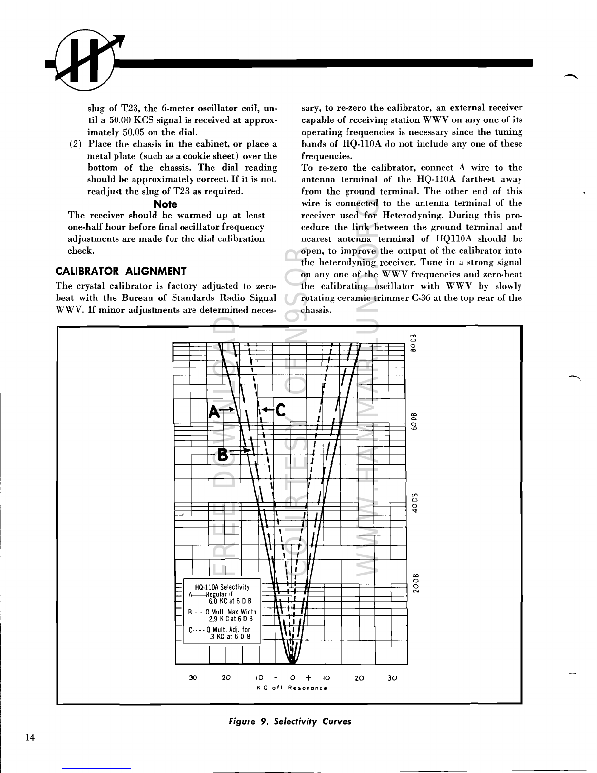
slug
of
T23,
the
6-meter
oscillator
coil,
un·
til
a 50.00
KCS
signal
is
received
at
approx-
imately
50.05
on
the
dial.
(2)
Place
the
chassis
in
the
cabinet,
or
place
a
metal
plate
(such
as a
cookie
sheet)
over
the
bottom
of
the
chassis.
The
dial
reading
should
be
approximately
correct.
If
it
is
not,
readjust
the
slug
of
T23
as
required.
Note
The
receiver
should
be
warmed
up
at
least
one-half
hour
before
final
oscillator
frequency
adjustments
are
made
for
the
dial
calibration
check.
CALIBRATOR ALIGNMENT
The
crystal
calibrator
is
factory
adjusted
to
zero-
beat
with
the
Bureau
of
Standards
Radio
Signal
WWV.
If
minor
adjustments
are
determined
neces-
sary,
to
re-zero
the
calibrator,
an
external
receiver
capable
of
receiving
station
WWV
on
anyone
of
its
operating
frequencies
is
necessary
since
the
tuning
bands
of
HQ-llOA
do
not
include
anyone
of
these
frequencies.
To
re-zero
the
calibrator,
connect A wire
to
the
antenna
terminal
of
the
HQ-IlOA
farthest
away
from
the
ground
terminal.
The
other
end
of
this
wire
is
connected
to
the
antenna
terminal
of
the
receiver
used
for
Heterodyning.
During
this
pro-
cedure
the
link
between
the
ground
terminal
and
nearest
antenna
terminal
of
HQIlOA
should
be
open,
to
improve
the
output
of
the
calibrator
into
the
heterodyning
receiver.
Tune
in a strong
signal
on
anyone
of
the
WWV
frequencies
and
zero-beat
the
calibrating
oscillator
with
WWV
by
slowly
rotating
ceramic
trimmer
C-36
at
the
top
rear
of
the
chassis.
~
-
-
-
-
-
\
, ,
I I
\
\
I
I I
\ \
I
..
\
,
C!
I
/
A-
\
,+-
,
,
I
, ,
E
s-
..-,
,
;
I I
\
\
,
, I
\
\
,
I
\
1\
\
, I I
I'
,
,
\
,
I
,
,
,
I
\'
,
,
\
,
\
,
,
\
,
I
,
HQ·ll0A
Selectivity
A
Regular
if
6.0
KC
at
6 DB
B - - Q
Mull.
Max
Width
,
I
2.9 KCat 6 DB
'I
C-··· QMull.
Adj.
for
\\
'I
.3
KC
at
6 D B
V
I
I
30
20
10
0 +
10
K C
off
Resonance
20
30
cr>
o
o
N
cr>
o
o
'<f
co
a
co
C)
o
<Xl
Figure 9.
Selectivity
Curves
14
FREE DOWNLOAD
COURTESY OF N9SOR
WWW.HAMMARLUND.ORG
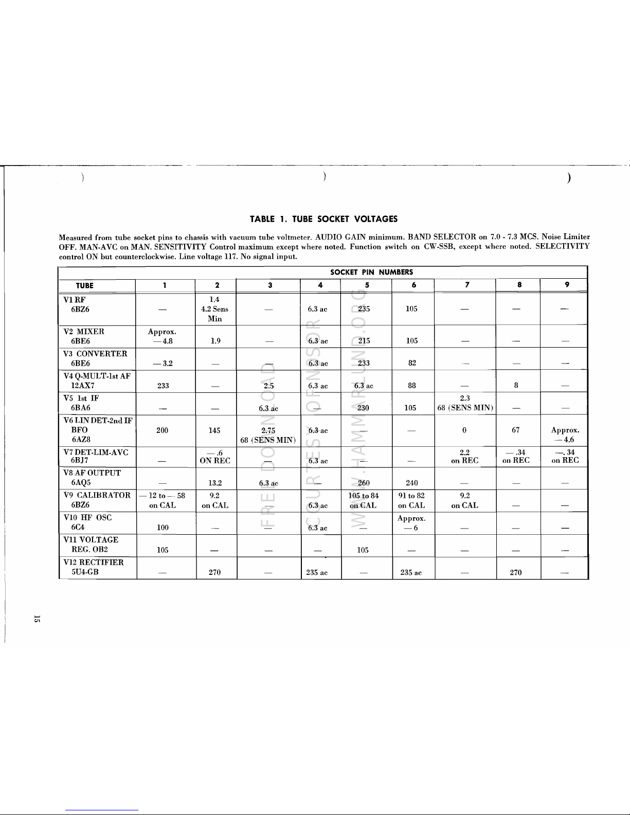
~=----
i
--~--~~---~_
..
)
)
)
TABLE
1.
TUBE
SOCKET
VOLTAGES
Measured from
tube
socket pins to chassis with vacuum
tube
voltmeter. AUDIO GAIN
minimum.
BAND SELECTOR
on
7.0 -7.3
MCS. Noise
Limiter
OFF. MAN-AVC
on
MAN. SENSITIVITY Control
maximum
except where noted.
Function
switch
on
CW.SSB, except where noted. SELECTIVITY
control ON
but
counterclockwise.
Line
voltage
II7.
No signal
input.
SOCKET
PIN
NUMBERS
TUBE
1 2 3
4 5 6
7 8
9
VIRF
1.4
6BZ6
-
4.2 Sens
-
6.3
ac 235
105
-
-
-
Min
V2
MIXER
6BE6
Approx.
-4.8
1.9
-
6.3
ac
215 105
-
-
-
V3
CONVERTER
6BE6
-3.2
-
-
6.3
ac
233
82
-
-
-
V4
Q-MULT-Ist AF
12AX7
233
-
2.5
6.3
ac
6.3 ac 88
-
8
-
V5
1st
IF
6BA6
-
-
6.3
ac
-
230 105
2.3
68
(SENS MIN)
-
-
V6
LIN
DET-2nd
IF
BFO
200
145 2.75
6.3
ac
-
-
0
67
Approx.
6AZ8
68
(SENS MIN)
-4.6
V7
DET-LIM-AVC
-.6
2.2
-.34
-.34
6BJ7
-
ONREC
-
6.3
ac
-
-
onREC
onREC onREC
V8AFOUTPUT
6AQ5
-
13.2 6.3 ac
-
260
240
-
-
-
V9
CALIBRATOR
-12
to-
58
9.2
105 to 84
91
to
82
9.2
6BZ6
on CAL
on
CAL
---
6.3 ac
on CAL
on
CAL
on
CAL
-
-
VIO
HF
OSC
6C4
100
- -
6.3
ac
--
Approx.
-6
- -
-
VII
VOLTAGE
REG.OB2
105
-
- -
105
- - -
-
VI2
RECTIFIER
5U4-GB
-
270
-
235 ac
-
235
ac
-
270
-
"'"'
CJl
FREE DOWNLOAD
COURTESY OF N9SOR
WWW.HAMMARLUND.ORG

......
0\
TABLE
2.
TUBE
SOCKET
RESISTANCES
Measured from
tube
socket pins
to
chassis
with
vacuum
tube
ohmmeter
with
pin
1 of V6, 6AZ8,
temporarily
grounded except
as
noted. AUDIO GAIN
ON
but
counterclockwise; Noise
Limiter
switch
ON;
SENSITIVITY
control
maximum
except
where
noted;
MAN - AVC
on
MAN; FUNCTION
switch
on
CW-SSB except where
noted;
TUNING
RANGE
on
7.0 - 7.3 MCS.
SOCKET
PIN
NUMBERS
TUBE
1
2 3
4
5
6
7 a
9
VI
RF
180
6BZ6
470K
1.7K Sens 0
-
4.7K
8.7K
0
-
-
Min
V2
MIXER
6BE6
22K
160 0
-
15K
8.7K
0
-
-
V3
CONVERTER
6BE6
22K
1.6 0
-
5.7K
12K 0 -
-
V4 Q MULT-lst AF
14.3K
12AX7
5.7K
2.2
Meg 4.3K Sel
-
-
505K
1 Meg
2.2K
0
max
150
V5
1st
IF
lOOK
0
-
0
5.7K
8.7K
10K Sens
- -
6BA6
mIn
V6 LIN. DET-2nd
200
lOOK
IFBFO
4.7K*
38K 10K Sens
-
0
110K Sens
0
52K
47K
6AZ8
mIn
min
V7
DET-LIM·A
VC
6BJ7 0
195K
0
-
0
470K
ONAVC
4.7K
2.2
Meg
2.2
Meg
V8
AF OUTPUT
6AQ5
500K
430
-
0
5.3K
4.7K
500K
-
-
V9
CALIBRATOR
Inf Inf
6BZ6
470K
4.7K
0
-
475Kon
105Kon
4.7K
-
-
Cal Cal
V10HF
OSC
6C4 9.7K
-
0
-
-
47K
0
-
-
V11
VOLTAGE
REG.OB2
8.7K
-
-
-
8.7K
-
0
-
-
V12
RECTIFIER
5U4-GB
-
5.1K
-
60
-
63
0
5.1K
-
Note*
With pin 1
of
V6
ungrounded and with pin 6 of
va,
6AQ5
grounded.
)
"
)
)
FREE DOWNLOAD
COURTESY OF N9SOR
WWW.HAMMARLUND.ORG
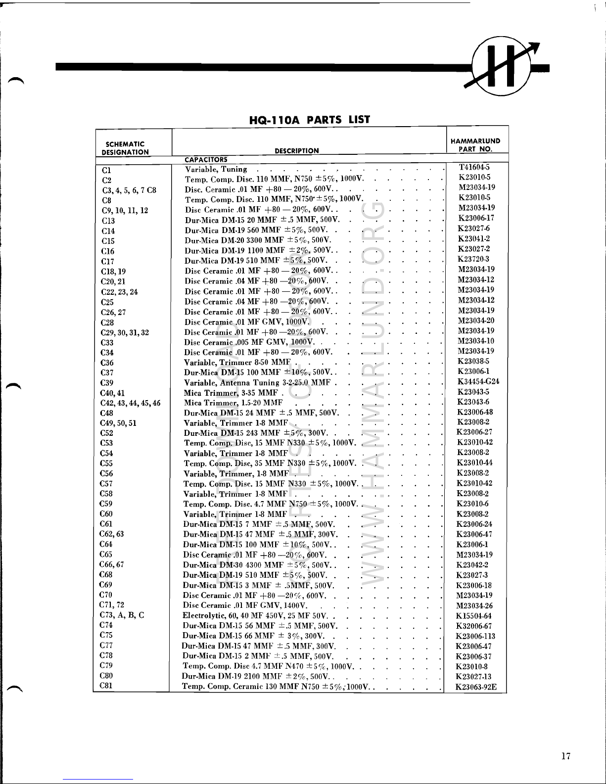
,.
----------------0
HQ·ll0A
PARTS
LIST
SCHEMATIC
IDESIGNATION
DESCRIPTION
CAPACITORS
Variable,
Tuning
Cl
Temp.
Compo
Oisc.
110
MMF, N750 ±5o/c, 1000V.
C2
Oisc. Ceramic
.01
MF
+80
-
200/0,
600V
..
C3, 4,
5,6,7
C8
Temp.
Compo
Oisc.
110
MMF, N750' ±
50/0,
1000V.
C8
Oisc Ceramic
.01
MF
+80
-
200/0,
600V
..
C9, 10, 11,
12
Our·Mica OM·15
20
MMF
±.5
MMF, 500V.
C13
Our·Mica OM·19
560
MMF ±
50/0,
500V.
C14
Our-Mica OM·20 3300 MMF ± 5
%,
500V.
C15
Our·Mica OM-19 1100 MMF ±
20/0,
500V
..
C16
Our-Mica OM·19
510
MMF
±5%,
500V.
C17
Oisc Ceramic
.01
MF
+80
-
200/0,
600V
..
C18,19
Oisc Ceramic
.04
MF
+80
-200/0, 600V.
C20,21
Oisc Ceramic
.01
MF
+80 -20%,
600V
..
C22,23,24
Oisc Ceramic
.04
MF
+80
-20%,
600V.
C25
Oisc Ceramic
.01
MF
+80
-
200/0,
600V
..
C26,27
Oisc Ceramic
.01
MF
GMV, 1000V.
C28
Oisc Ceramic
.01
MF
+80
-20%,
600V.
C29,
30,
31,
32
Oisc Ceramic
.005
MF GMV, 1000V.
C33
Oisc Ceramic
.01
MF
+80 -20%,
600V.
C34
Variable,
Trimmer
8·50
MMF .
C36
Our·Mica OM·15
100
MMF
±10%,
500V
..
C37
Variable, Antenna
Tuning
3-2·25.0
MMF .
C39
C40,41 Mica
Trimmer,
3·35 MMF .
Mica
Trimmer,
1.5-20
MMF
C42,43,44,45,46
Our·Mica
OM-15
24
MMF
±.5
MMF,500V.
C48
C49,
50,
51
Variable,
Trimmer
1-8
MMF
Our·Mica
OM-15
243
MMF
±5%,
300V.
C52
Temp.
Compo
Oisc,
15
MMF N330
±50/0,
1000V.
C53
C54
Variable,
Trimmer
1·8 MMF
Temp.
Compo
Disc,
35
MMF N330
±50/0,
1000V.
C55
C56 Variable,
Trimmer,
1·8 MMF
C57
Temp. Compo Oisc.
15
MMF N330
±50/0,
1000V
..
C58
Variable,
Trimmer
1·8
MMF
C59
Temp. Compo Oisc.
4.7
MMF N750
±50/0,
1000V
..
C60
Variable,
Trimmer
1-8
MMF
C61
Our-Mica
OM-15
7 MMF
±.5
MMF, 500V.
C62,63
Our-Mica OM.15
47
MMF
±.5
MMF, 300V.
..
C64
Our-Mica
OM-15
100
MMF ±
10%,
500V
..
C65
Oisc Ceramic
.01
MF
+80
-20%,
600V.
C66,67
Our·Mica OM-30
4300
MMF
±5%,
500V
..
C68
Our-Mica
OM-19
510
MMF
±50/0,
500V.
C69
Our-Mica
OM-15
3 MMF ± .5MMF,500V.
C70
Oisc Ceramic
.01
MF
+80
-20%,
600V.
C7l,72
Oisc Ceramic
.01
MF GMV, 1400V.
cn, A, B, C
Electrolytic, 60,
40
MF 450V,
25
MF
50V.
C74
Our-Mica OM·15
56
MMF
±.5
MMF, 500V.
C75
Our-Mica
OM-15
66
MMF ±
3%,
300V.
cn
Our-Mica OM·15
47
MMF
±.5
MMF, 300V.
C78
Our-Mica OM·15 2 MMF
±.5
MMF,500V.
C79
Temp.
Compo
Oisc
4.7
MMF N470
±5%,
1000V.
C80
Our-Mica
OM-19
2100
MMF
±2%,
500V
..
C81
Temp.
Compo
Ceramic
130
MMF N750
±5%;1000V
..
I
HAMMARLUND
PART NO.
T41604·5
K23010·5
M23034·19
K23010·5
M23034.19
K23006·17
K23027-6
K23041·2
K23027·2
K23720-3
M23034·19
M23034·12
M23034-19
M23034·12
M23034·19
M23034·20
M23034·19
M23034·10
M23034·19
K23038-5
K23006-1
K34454-G24
K23043·5
K23043-6
K23006·48
K23008-2
K23006·27
K23010-42
K23008·2
K2301044
K23008-2
K2301042
K23008-2
K23010-6
K23008-2
K23006·24
K23006·47
K23006-1
M23034·19
K23042-2
K23027·3
K23006-18
M23034-19
M23034·26
K15504·64
K32006·67
K23006·113
K23006·47
K23006-37
K23010·8
K23027·13
K23063-92E
17
FREE DOWNLOAD
COURTESY OF N9SOR
WWW.HAMMARLUND.ORG
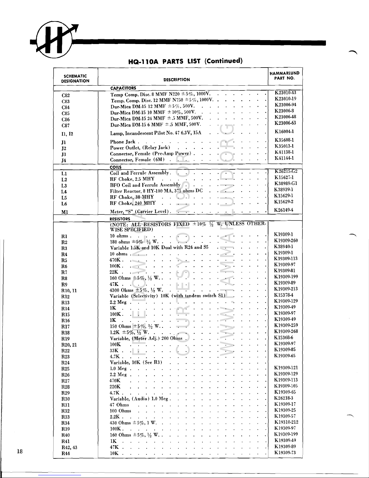
HQ-ll0A
PARTS
LIST
(Continued)
SCHEMATIC
DESIGNATION
DESCRIPTION
HAMMARLUND
PART
NO.
CAPACITORS
C82
C83
C84
C85
C86
C87
11,12
J1
J2
J3
14
LI
L2
L3
L4
L5
L6
MI
R1
R2
R3
R4
R5
R6
R7
R8
R9
RIO,
11
R12
R13
RI4
R15
R16
R17
R18
R19
R20,
21
R22
R23
R24
R25
R26
R27
R28
R29
R30
R31
R32
R33
R34
R39
R40
R41
R42,43
R44
Temp
Compo
Disc. 8 MMF N220
±50/0,
IOOOV.
Temp.
Compo
Oisc.I2
MMF
N750
±5o/c,
IOOOV
.•
Our.Mica OM·I5
12
MMF ±5o/c, 500V.
Our.Mica OM·I5
10
MMF ±
100/0,
500V.
Our.Mica OM·I5
24
MMF
±.5
MMF, 500V.
Our.Mica OM·I5 6 MMF
±.5
MMF, 500V.
Lamp, Incandescent
Pilot
No.
47
6.3V, 15A
Phone
Jack.
Power
Outlet, (Relay
Jack)
Connector, Female (Pre·Amp
Power)
.
Connector, Female (6M)
COILS
Coil
and
Ferrule
Assembly.
RF
Choke,
2.5
MHY
BFO Coil
and
Ferrule
Assembly
Filter
Reactor, 8 HY·100 MA,
375
ohms OC
RF
Choke,
38
MHY
RF
Choke,
240
MHY
Meter,
"S"
(Carrier
Level) .
RESISTORS
(NOTE:
ALL RESISTORS
FIXEO
±10%
!,6
W.
UNLESS
OTHER·
WISE
SPECIFIEO)
10
ohms.
180
ohms
±5%
% W.
Variable
l.5K
and 10K Oual with R24
and
S5
10
ohms.
470K.
lOOK.
22K
160 Ohms
±50/0,
lh
W
..
47K
4300
Ohms ± 5
0/0,
!,6
W.
Variable (Selectivity) 10K (with tandem switch
SI)
2.2
Meg
IK
lOOK.
IK
150
Ohms
±50/0,
!,6
W
..
1.2K
±5%,
!,6
W.
Variable,
(Meter
Adj.)
200
Ohms
lOOK
33K
4.7K.
Variable, 10K (See R3)
1.0
Meg
2.2
Meg
470K
220K
4.7K.
Variable,
(Audio)
1.0
Meg.
47
Ohms
100
Ohms
2.2K.
430
Ohms ±
50/0,
1 W.
lOOK.
160
Ohms
±5%,
!,6
W
..
1K
47K
10K
K230IO·43
K230IO·19
K23006·94
K23006.8
K23006·48
K23006·63
KI6004·1
K35608·1
K35013·1
K41138.1
K41144·1
K26215·G2
KI5627·1
K38989.G1
K38939·1
KI5629·1
K15629·2
K26149·4
K19309·1
K19309·260
K38940·1
K19309·1
K19309·113
K19309·97
K19309·81
K19309·199
K19309·89
K19309·213
KI5378-4
K19309·129
K19309-49
K19309·97
K19309·49
K19309·259
KI9309·268
K15368·6
K19309·97
K19309·85
K19309·65
K19309·121
K19309·129
K19309·113
K19309·105
K19309·65
K26218·3
K19309·17
K19309·25
KI9309·57
K19310·212
K19309-97
K19309·199
K19309-49
KI9309·89
K19309·73
18
FREE DOWNLOAD
COURTESY OF N9SOR
WWW.HAMMARLUND.ORG
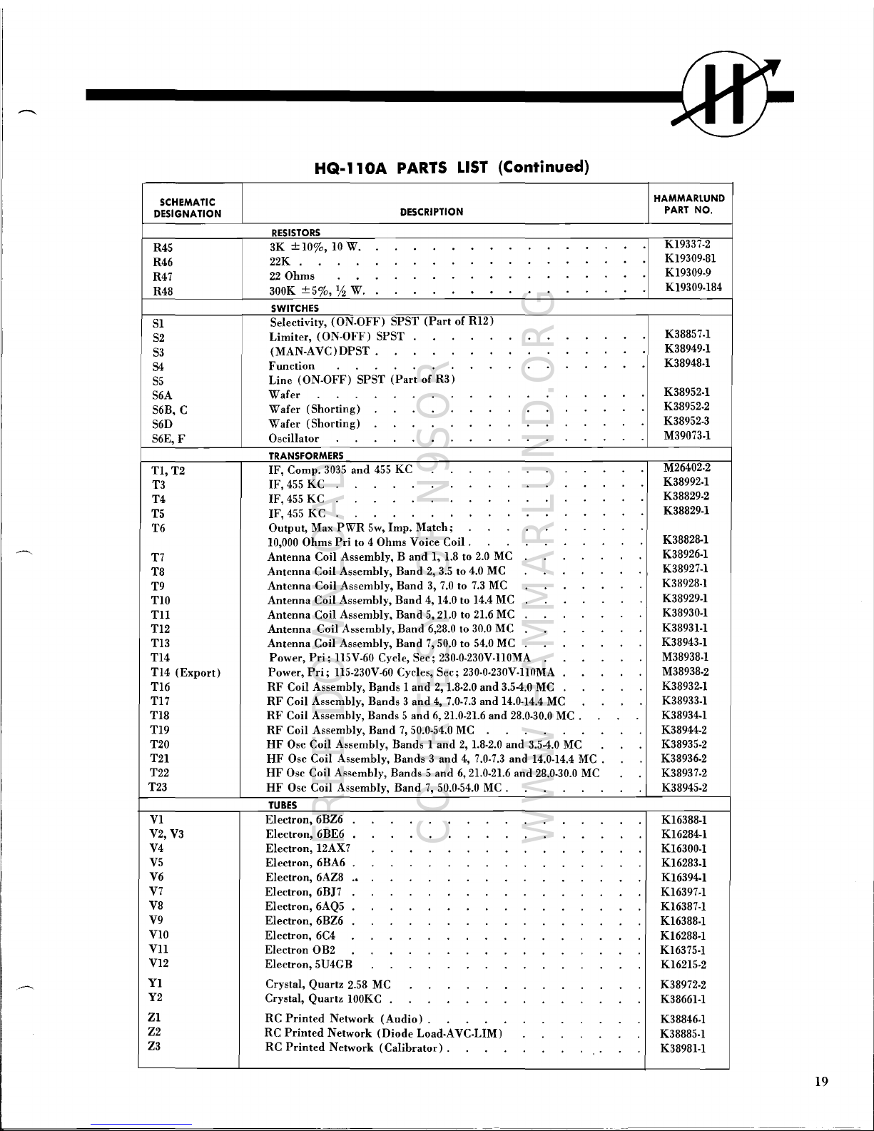
HQ·ll0A
PARTS
LIST
(Continued)
HAMMARLUND
SCHEMATIC
PART
NO.
DESCRIPTION
DESIGNATION
RESISTORS
K19337·2
3K
± 10%, 10W.
R45
K19309·81
22K
R46
K19309·9
22
Ohms
R47
K19309·184
300K
±5%,
Y2
W.
R48
SWITCHES
Selectivity, (ON.OFF) SPST
(Part
of R12)
SI
K38857·1
Limiter, (ON-OFF) SPST
S2
K38949·1
(MAN·AVC)DPST.
S3
K38948·1
Function
S5
54
Line (ON·OFF) SPST
(Part
of R3)
K38952·1
Wafer
S6A
K38952·2
Wafer (Shorting)
S6D
S6B, C
K38952·3
M39073-1
Wafer (Shorting)
Oscillator
S6E, F
TRANSFORMERS
M26402·2
IF,
Compo
3035
and
455
KC
TI,T2
K38992·1
IF,
455
KC
T4
T3
K38829·2
T5
IF,
455
KC
K38829·1
T6
IF,
455
KC
Output, Max
PWR
5w, Imp. Match;
10,000
Ohms
Pri
to 4 Ohms Voice Coil .
K38828-1
T7
K38926·1
K38927·1
Antenna Coil Assembly,
Band
1,
1.8
to
2.0
MC
Antenna Coil Assembly, Band
2,
3.5
to
4.0
MC
T9
T8
K38928-1
TIO
Antenna Coil Assembly, Band
3,
7.0
to
7.3
MC
K38929·1
TIl
Antenna Coil Assembly, Band
4,
14.0
to
14.4
MC
K38930·1
TI2
Antenna Coil Assembly, Band
5,
21.0
to
21.6
MC
K38931·1
T13
Antenna Coil Assembly, Band
6,28.0
to
30.0
MC
K38943·1
T14
Antenna Coil Assembly, Band 7,50.0 to
54.0
MC
M38938·1
T14
(Export)
Power,
Pri;
115V·60 Cycle, Sec; 230·0·230V·IlOMA
M38938·2
T16
Power,
Pri;
115·230V-60 Cycles, Sec; 230·0·230V·IIOMA
K38932·1
Tl7
RF
Coil Assembly, B,lnds I
and
2,
1.8·2.0
and
3.54.0
MC
K38933·1
T18
RF
Coil Assembly, Bands 3
and
4,
7.0·7.3
and
14.0-14.4
MC
K38934·1
T19
RF
Coil Assembly, Bands 5
and
6,
21.0-21.6
and
28.0·30.0
MC
.
RF
Coil Assembly, Band 7,50.0·54.0
MC
K38944·2
T20
HF
Osc Coil Assembly, Bands 1
and
2,
1.8·2.0 and 3.54.0
MC
K38935·2
T21
HF
Osc Coil Assembly, Bands 3
and
4,
7.0·7.3
and 14.0·14.4
MC
. K38936·2
T22
HF
Osc Coil Assembly, Bands 5
and
6,21.0.21.6
and
28.0·30.0
MC
K38937·2
T23
HF
Osc Coil Assembly, Band 7,50.0·54.0
MC
. K38945·2
TUBES
VI
Electron, 6BZ6
K16388·1
V2,
V3
Electron, 6BE6
K16284·1
V4
Electron, 12AX7
K16300·1
V5
Electron, 6BA6 .
K16283·1
V6
Electron, 6AZ8
..
K16394·1
V7
Electron, 6BJ7
K16397·1
V8
Electron, 6AQ5 K16387·1
V9
Electron, 6BZ6
K16388·1
VI0
Electron,
6C4
K16288·1
Vll
Electron OB2
K16375·1
V12
Electron,5U4GB
K16215·2
Yl
Crystal, Quartz 2.58
MC
K38972·2
Y2
Crystal, Quartz 100KC
K38661·1
ZI
RC
Printed
Network
(Audio)
.
K38846·1
Z2
RC
Printed
Network
(Diode
Load.AVC.LIM)
K38885·1
Z3
RC
Printed
Network
(Calibrator)
.
K38981·1
19
FREE DOWNLOAD
COURTESY OF N9SOR
WWW.HAMMARLUND.ORG

m
HQ·ll0A
PARTS
LIST
(Continued)
HAMMARLUND
SCHEMATIC
PART
NO.
DESCRIPTION
DESIGNATION
MISCELLANEOUS
ITEMS
K38874.G2
CMC (STD.)
Clock, Telechron Auto·Timer
K38874-G3
CMC
(EXPORT)
Clock, Telechron Auto·Timer (l15.230V) .
M38877-1
Crystal,
Panel
Clock Window
K26216-3
Knob,
%" Dia.
K26379-1
Clock Shaft .
K29619-9
Snap Button
K41140·1
Shell
K41139·1
Connector, Male
K35610·1
Plug
K26226-2
Knob, 2" Dia.,
White
Line
K26216-2
Knob,
%" Dia.
K26224-1
Knob,
I"
Dia.
K26229-1
Knob,
I
Va"
Dia.
(Poihter)
.
K26226·1
Knob,
2"
Dia.
41383·1
Instruction Manual Issue I
Continued
from
page
10
corrections,
that
the
proper
trimmer
is
selected,
then
make
the
adjustments
very
slowly
and
carefully.
This
procedure
is
only
being
incorporated
in
this
resume
for
the
experienced
amateur
operator,
in
an
effort
to
avoid
the
return
of
the
receiver
with
the
resultant
delay.
If
you
are
in
the
least
bit
hesitant
about
making
these
adjustments,
please
do
not
attempt
it.
We
might
also
point
out
at
this
time
that
any
minor
adjustments
of
the
oscillator
will
in
no
way
effect
the
tracking
of
the
oscillator
with
the
R.
F.
and
mixer
circuits
involving
complete
realign-
ment
of
the
front
end
of
the
receiver.
Complete
realignment
of
the
front
end
should
only
be
at-
tempted
when
the
necessary
equipment
and
knowl-
edge
is
available.
20
FREE DOWNLOAD
COURTESY OF N9SOR
WWW.HAMMARLUND.ORG
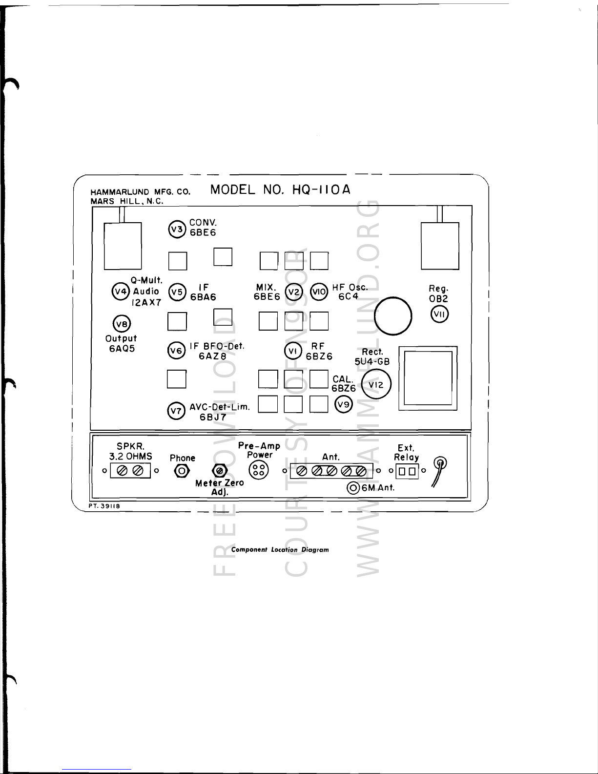
HAMMARLUND
MFG.
CO.
MODEL
NO.
HQ-IIOA
MARS
HILL,
N.C
II
Q·-Mult.
eAUdiO
12AX7
G)
Output
6AQ5
SPKR.
3.2
OHMS
01
@@
1
0
~CONV.
~6BE6
II
o
o
CIOO
Reg.
OB2
e
D
Reet.
5U4-GB
DDD~:}68
DDD8
Q
IF
BFO-Det.
v:.::J
6A
Z 8
D
G AVC-Det-Lim.
'-Y
6BJ7
D
@
6~~6
D
Pre-Amp
Ext.
Phone
Power Ant. Relay 1
@ @ @
01
@~~
1
0
o[[QJo
Met:~J~ero
@6M
Ant.
PT.
39118
'---------
-
--
-------
-
--
--------~
Component
Location Diagram
FREE DOWNLOAD
COURTESY OF N9SOR
WWW.HAMMARLUND.ORG
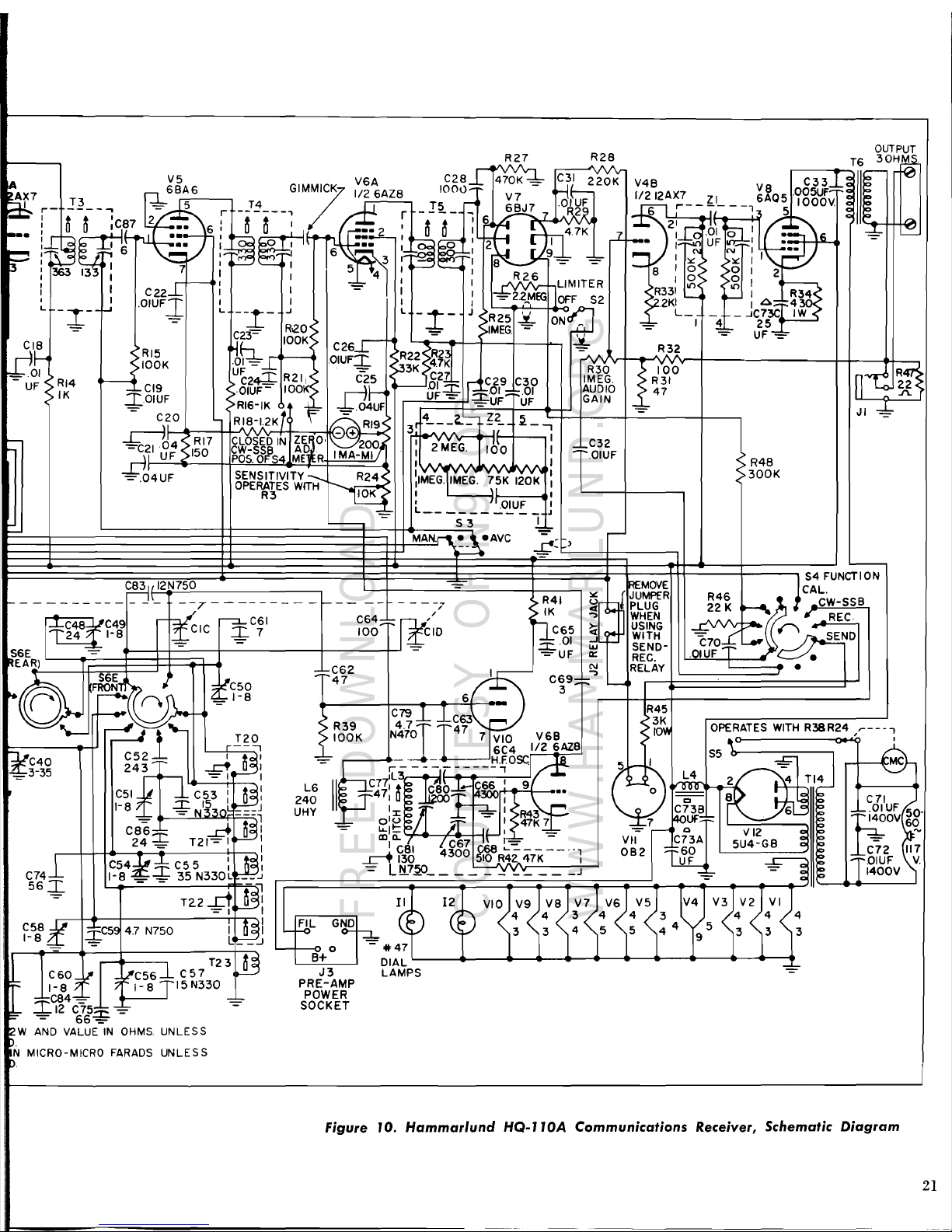
OUTPUT
R27 R28
T6
30HM
R48
>300K
-
Oll~
,0IUFI.
I
,>~.Z~>~~K
r'~"I\rlH"""""'!Y'r-t---------+~----<~--,
UF....J.... > =
).'3K
>"
R30
100
;n
>
CZ..J;:
R21,
> C25 C27 lr< C29
C30
IMEG.
>
R31
n-vr<'
R
·OIUF- lOOK>
.-f~
'--8~=E=-llxO'_:::
.01
AUDIO
c>
47
III
~
5{
< RI6-IK
-#=-
-:bci4UF
UF
UF
GAIN
~
-:b
RI8.-1.2K Ii
~RI9S
3114
_,-,=""
~2_
~_.,
JI
-=
Yo.
--+-)
'A
II
CLOSED
IN
ZE
0,
200J'
1
1
.
I C32
CW-SSB
AD.
I MA
MI
f I 2
MEG.
100
I
;:~'OIUF
POS.OFS4
ME
R - I I
SENSITIVITY..=:-:--,-
R24< IIMEGIMEG
'75K
'120K
I
OPEFW~ES
WITH
,--
~
: . .
\I
:
-=--
L
'~O.!.U~
_ 1
'----
-
S3
.!,,~
MA~eAVC
~:)
< RI5
>IOOK
~
CI9
I,.OIUF
-
C20
-.r:::-id4
< R
17
-CI~IUF'
">150
~4UF
~~~
jr;
6
363m
:
I
I
-~--I-'
~f
-
UF
<) RI4
< IK
'---
J
,S4 FUNCTION
R46
CAL.
22
K .........
~
.~C,""W,--S,,-,S:<..:B:..,
r"
,
REC.
.."f;;.')~
-(
n
~
(:70
L.-\
~END
.OIUF
•
•
~MOVE
[
JUMPfR
~
PLUG
WHEN
USING
WITH
SEND-
REC.
RELAY
:..:
~
..,
~
-J
W
II::
C\I
:>
R41
> IK
QC65
.:::r:
.01
=UF
CID
C8311 12N750
!----------
-
JI_
--7--------
-'-----
I
~C49
,--:::J.L'...
~C61
C64;:
1-
~-
1-8 .:t
CIC
I.
7
100
S6E~~==i=:~~~~~~-~~i------1~;-I--'
~EAR)
I
I----"-..
_,
....J!..
U
,..,...
L~_.'
I~"I·='
\6
-===-..'-
..
I I
aclf;;o
I
II
..,
-"
0 ' Z I
r--
UFI·'~;::::·
6
~
VOl"",
9 _ I
C\
N I
;~;;.I
:
~
'-
I
5_
43"
~~,
8 =
-.!o-
_ I
><: ><:
I I
r""""'"'"
I,
I I R2 6 8 I 0
>0'
2
I I I I \..,J::.YYY:
lLiMITER
<
R33:
~
>
~
I
~
: I
I:
-=
Z2~MEG
JOFF
52
92KI
'-
~:
A;:
f'~34
L.
--~-
..J L
-~
_ J <
R25
y <
L_
_ _
...JC73C
IW
-L
R"O <
ON
~_b-
I 4
25
- "
IMEG
= -
;;);.=-
UF
-=_~
~E.-
lOOK:
CZ6r-
)~~{
~
R3?
~
S6E
;:,~~2
C69;:~'"
L..-...4
6 _
3
"[J)..
'F:~
Ztj5g
L
R45
>3K
C79 T
>
R39
4.7
-!-
;:~C63
SIO~
OPE~TES
WITH
R38R24 ,"'---i
T20
> lOOK
N47j
47
7
VIO
V6B
6C4
1/2 6AZ8
'-..-
~l---
S5"
~
1it::l..!r=--rC-4-0-
.......
-t'
C52...;:::
~-a~
~
-"~---'H.F.OSC
4
1~3-35
243
~~:
~ I ~~rO:;
TI4J
~
C51
frr
C53
: I
~~:
L6
1lllHpcxtf
-
~~;:-;~~ ~ ~
..
-
1-8
..:r.
15
_L~J
240
1110
I
)_~vv
'..-~
:
.>
o c 8 :
I.
~II~
I::
......
01
UF
:~
50-,f,Z3B
6~1I!':.'
C71
- -1
UHY
~
oliS
;:~
=
1~~R7
~
7
rtUUF
~
E4_00V
69.
C86:::::r::L-
...,dl
D~I
-
u..1~
:!
1<
_
-=
----< Q V
12
~
.-
24
=
T21=1~:
lDlQ.
I..
C67 J
1~
-
6~2
;:C~6A
5U4-GB
~
C72
117
~
f!d
4300
~~124iK--·-1
L....!.LL
~
II:OIUF
V.
\ C
54
...u±
C55
:
J3:
=
LN.7.2.CL
'::!~
J
C74~
1-8'~
_
35
N330~
__
.J
- L... -
~
L
11400V
56~
- - !
51
II
12~
bVIO
V9
V8
V7
V6
V5 V4
V3
V'~
VI
T<?Z-£1LM:
G
('~
(b
4 4 3 4 4 3 4 4 4
A
L
'~r---,
~
" 3 3 4 5 5 4 4 5 3 3 3
f_
5
:!,
I~C5~
4.7
N750
~~J
,~
9
L-1----:9
0 -
.47
B+
DIAL
L---
......
-~~___4>___4-
V6A
C28~
(r)
;Z'O:
V4B
_~
V5
C33
~
feJ
6BA6
GIMMI/
1/2
6AZ8
IOOu~
V7
-
rJC
1/21ZAX7 ZI
aQ5
.005U";:
-~
~
5
----~
T3
r
_J~
, / I r
_I~_
~
6BJ7
7
.~~~~
~
r---7,---:" 5 1000Y.
~
~
o 0
;C,~7
Z
..
6:
0 0 I I
••
!!
:
~[Jftf-t
4.7K.J..
.---.
~
I.t---.
TI r
21~
01
:~
........-
......
~~-+_-
.....-.......
-____,.---.
C60_\.Jr
J3
LAMPS
~
-lJ'C56~
C57
T231J3
PRE-AMP
POWER
1-8 ?
"I
- 8 I 15N330
~C84~
-="=-
SOCKET
~
.I:.12
C75.x,
~
-=
=
66=
'2W
AND
VALUE
IN
OHMS
UNLESS
D.
N MICRO-MICRO
FARADS
UNLESS
P
Figure 10.
Hammarlund
HQ-llOA
Communications
Receiver, Schematic Diagram
21
FREE DOWNLOAD
COURTESY OF N9SOR
WWW.HAMMARLUND.ORG
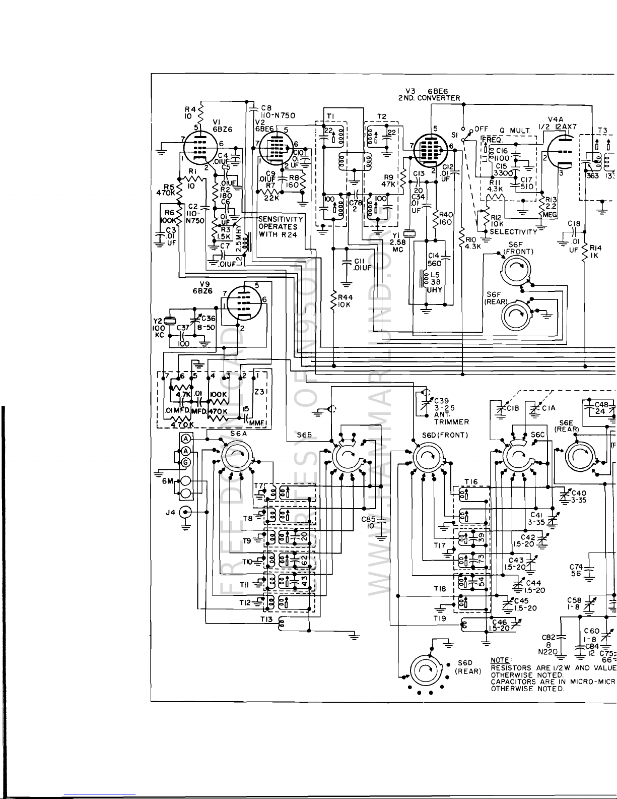
V3
68E6
2
NO.
CONVERTER
I i
V4A
1/2
12AF
T3
r-
-
I
I
I
I
I
I
I
I
I
I
I
I
L
CI8
-J!01
UF
R44
10K
--z--n
I
Z31
I
I
C85
10
1
C74
0
0
[
363 13:
-~-
RI4
IK
56
-=!=-
L.,
I
--=~~
~=-=
...
~
TI3
£560
~:
(REAR)
•
• •
•
C60
1- 8
C84-
.I..12
C75;
NOTE' =
66-:
RESISTORS
ARE
1/2 W
AND
VALUE
OTHERWISE NOTED.
CAPACITORS ARE
IN
MICRO-MICR
OTHERWISE NOTED.
FREE DOWNLOAD
COURTESY OF N9SOR
WWW.HAMMARLUND.ORG
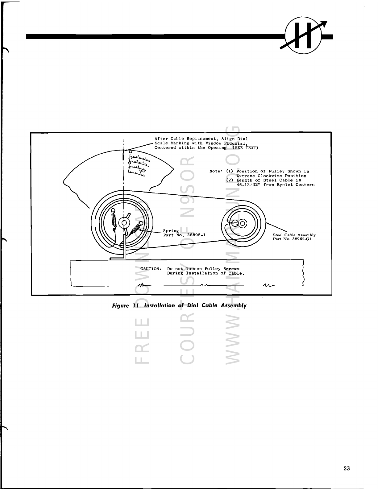
the
Opening.
(SEE TEXT)
Note:
(1)
Position
of
Pulley
Shown
Extreme
Clockwise
Position
(2)
Length
of
Steel
Cable
is
46-13/32"
from
Eyelet
Centers
Spring
Part
No.
38895-1
IIi
After
Cable
Replacement,
Align
Dial
Scale
Marking
with
Window
Fiducial,
Centered
within
in
CAUTION:
Do
not
loosen
Pulley
Screws
During
Installation
of
Cable.
Figure J
J.
Installation
of
Dial Cable
Assembly
23
FREE DOWNLOAD
COURTESY OF N9SOR
WWW.HAMMARLUND.ORG

__
_
m
I
I
\:------------
'\
: I
I
I
~-+-YELLOW-BLACK
I
I
I
())-+-+--+-
BLACK-WHITE
I
I
I
I
THIS POINT MUST
:
-*:~;~
..
I
I
BE
SOLDERED
A
'~/
L
J
RED-BLACK
:
(PLASTIC
LEAD)
'_
_
POWER TRANS.
f-.d:H-+------+-BLACK-YELLOW
BLACK
BLACK-GREEN
A.C.
LINE
SHORT
~CREW
1/4
LG.
T1NNERMAN NUT
PLACE BETWEEN
CLOCK PLATES
AT
POSITION A
A
ONLY
Figure J2.
Standard
Clock
(J
J5V
50
or
60
CPS)
Wiring
Diagram
24
FREE DOWNLOAD
COURTESY OF N9SOR
WWW.HAMMARLUND.ORG
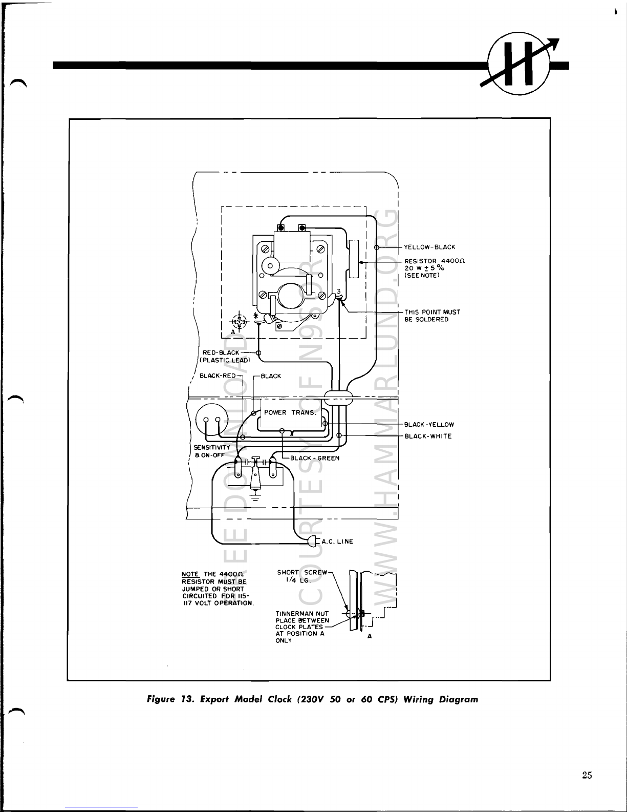
~-t--+-
RESISTOR
BLACK
'--------J-II--t-
THIS POINT MUST
~===e::;;:====~P\ttt----t
BLACK -YELLOW
I~~~=e:===~§§~~~~
~Pl-----t-BLACK-WHITE
RED-BLACK
(PLASTIC
LEAD)
I BLACK-RED
I
YE
LLOW-
BLACK
4400n
20
W + 5
0/
0
(SEE NOTE)
BE
SOLDERED
'---------"""'-J-
A.C.
LINE
NOTE THE
4400n.
SHORT
SCREW1--~
RESISTOR MUST BE
1/4
LG. I
JUMPED
OR
SHORT
I
CIRCUITED FOR
115-
117
VOLT OPERATION.
__
J
I
TINNERNAN
NUT -
__
J
PLACE I!ETWEEN J
CLOCK
PLATES AT POSITION A A
ONLY
Figure J
3.
Export
Model
Clock
(230V
50
or
60
CPS)
Wiring
Diagram
25
FREE DOWNLOAD
COURTESY OF N9SOR
WWW.HAMMARLUND.ORG

m
MEMORANDA
26
FREE DOWNLOAD
COURTESY OF N9SOR
WWW.HAMMARLUND.ORG
THE
HAMMARLUND
MANUFACTURING
COMPANY
Standard
Warranty
The Hammarlund Manufacturing Company, warrants this equipment to
be
free from defects
in workmanship
and
materials under normal
and
proper use
and
service for
the
uses
and
purposes for which it
is
designed,
and
agrees
to repair
or
replace, without charge, all parts
thereof showing such defects which
are
returned for inspection to
the
Company's factory,
transportation prepaid, within a period of
90
days
from
date
of delivery, provided such inspec-
tion discloses
to
the
satisfaction of
the
Company
that
the
defects
are
as
claimed,
and
provided
also,
that
the equipment
has
not been altered, repaired, subjected to misuse, negligence
or
accident,
or
damaged
by lightning, excessive current
or
othelWlse,
or
had
its serial number
or
any
part
thereof altered, defaced,
or
removed. Tubes shall
be
deemed to
be
covered by
the
manufacturer's
standard
warranty
applicable thereto,
and
such items shall
be
and
are
hereby
excluded from the provisions
of
this warranty. Pilot lamps.
and
fuses
are
not
guaranteed
for
length of service.
Except
as
herein specifically provided, no warranty, express
or
implied, other than
that
of
title, shall
apply
to
any
equipment sold hereunder.
In
no event shall the Company
be
liable
for
damages
by
reason
of
the
failure
of
the
equipment to function properly
or
for
any
consequential damages.
This
Warranty
is
valid for
the
original owner of the equipment,
and
is contingent upon receipt
of the Warranty Registration Card by
the
Company.
No
equipment shall
be
returned to the
factory for repairs under warranty unless written authorization
Is
obtained by
the
Company,
and
the
equipment
Is
shipped
prepaid
by
the
owner. The Company maintains Authorized
Service Stations, names
and
locations of which will
be
sent upon request of the owner.
The Hammarlund Manufacturing Company
A
Giannini
Scientific
Co.
53
West
23rd
Street,
New
York
10,
N.
Y.
Export Deportment,
13
East 40th Street,
New
York 16, N.
Y.
The poUcy
of
the Hammarlund Manufacturi"" Company,
i.
one
of
continued
im....-nt
in
de.ign
and
manufoclur.
wherever
and
when.ver
possibl.,
to
provide
thehi.h••t
attoinable
quality
and
performance.
Henc.,
spacifica-
Ii_,
flnI
.....
,
.tc.
are
subiect
to
change
without
notic.
and
without alSump-
tialt
by
Hammorlund
of
any
obligalion
or
re_nsibility
to
provide such
__
as
IlIGy
be
cha""ed,
added
or
dropped
from previous production
runs
of
this
.....
''''''.nt.
Hammarlund
Manufaduring
Company
A Giannini Scientific Co,
53 West 23rd Street, New
York
10,
N.
Y.
Export
Department:
13
East
40th
Street,
New
York
16,
N.
Y.
DO NOT MAKE
ANY
RETURNS
WITHOUT AUTHORIZA'nON FROM
EITHER
NEW YORK
OFFICE
OR
FACTORY.
ALL
AUTHORIZED
RETURNS
SHOULD
BE
SHIPPED
TOFACTORYr HAMMARLUND MANUFACTURING
CO., MARS HILL, NORTH CAROLINA. DO NOT
SHIP
TO NEW YORK
OFFICE.
FREE DOWNLOAD
COURTESY OF N9SOR
WWW.HAMMARLUND.ORG

ESTABLISHED
1910
ISSUE
7
62
MANUAL
PART NO.
41383·1
FREE DOWNLOAD
COURTESY OF N9SOR
WWW.HAMMARLUND.ORG
 Loading...