


\
~,
"',
'\
\
'\
\
\
\
\
I(
. \
jt
//
//
I::
AND
.-
O~.RATING
l
I
INSTRUCTIONS
D.SCRI.-TION
----~---
I
HQ-IO
A
(
COMMUNICATIONS
»
\.
RECEIVER
~
\
\
~
Hammarlund Manufaduring Company
A Giannini Scientific Co.
73-88
HAMMARLUND
DRIVE
MARS
HILL.
NORTH
CAROLINA
9001-06-00005
FREE DOWNLOAD
COURTESY OF N9SOR
WWW.HAMMARLUND.ORG

THE
HQ-IOOA
SERIES
COMMUNICATIONS
RECEIVERS
INSTRUCTION
AND
SERVICE
INFORMATION
ESTABUSHED
19]0
ISSUE
3
1r1
order
to
receive the
full
unconditional
gO-day
warranty against
defective material
arJd
workmanship in this receiver, the warranty
card must
be
filled
out and mailed
within
two weeks
of
purchase.
Please
refer
to
serial number of warranty in correspondence.
THE
HAMMARLUND MANUFACTURING CO.
73-88
Harnrnarlund
Drive
Mars
Hill,
North
Carolina
28754
II
I
FREE DOWNLOAD
COURTESY OF N9SOR
WWW.HAMMARLUND.ORG

@
....................................
..-
Figure
I.
Tbe
HQ·IOOA
Receiver
TUBE
AND
DIODE
COMPLEMENT
Symbol
Type Tube
Function
VI
6BZ6
Pentode
RF
Amplifier
V2
6BE6
Pentagrid
Converter
Mixer
V3
6C4
Triode
HF
Os
cillator
V4A
1!212AX7
Triode
First
AF
Amplifier
V4B
1!212AX7
Triode
Q-Multiplier
V5
6BA6
Remote
Cutoff
Pentode
First
IF
Amplifier
v6
6BA6
Remote
Cutoff
Pentode
Second
IF
Amplifier
V7
6BV8
Twin
Diode,
Triode
Detector,
Serie s Nois e Limiter,
BFO
V8
6AQ5
Beam
Power
Amplifier
Audio
Power
Output
V9
OB2
Gas
Filled
Diode
Voltage
Regulator
CRI
Cer
72c
Diode,
Silicon
Rectifier
CR2
Cer
72c
Diode,
Silicon
Rectifier
ii
FREE DOWNLOAD
COURTESY OF N9SOR
WWW.HAMMARLUND.ORG

INTRODUCTION
The
Hammarlund
HQ-l
OOA
is
an
all-new
communications
receive
r
representing
entirely
new
concepts
in
electrical
and
mechanical
design.
It
will
provide
years
of
top
performance
with
minimum
maintenance.
The
HQ-100A
series
receivers
have a self-contained
power
supply
and
a
universal
transformer
capable
of
operation
from a 117
volt
60
cp/s
or
220/230
volt
50/60
cp/s
source,
provided
the
proper
adapter
plug
(P2)
is
installed.
The
HQ-lOOA
is a superheterodyne
receiver
with a frequency
cover-
age
continuously
tunable
from
540
KCS
to
30
MCS
with
extremely
fine
control
in
separation
of
crowded
signals.
A
very
high
signal-to-noise
ratio
plus
the
famous
Hammarlund
noise
limiter
circuit,
permits
full
use
of
the
receiver's
excellent
sensitivity
on
the
weakest
signals.
A
Q-Multiplier
is
provided
for
varying
the
selectivity
of
the
receiver.
Red
segments
on
the
main
tuning
dial
indicate
wherein
the
majority
of
the
international
short
wave
stations
can
be
located.
Electrical
band
spread
tuning
is
provided
with
direct
calibration
eve
ry
10
KCS
on
80,
40,
and
20
meter
bands;
every
20
KCS
on
the
15
meter
band
and
every
50
KCS
on
the
10
meter
band.
In
addition,
an
arbitrary
band
spread
logging
scale
is
provided
for
use
throughout
the
tuning
range
of
the
receiver.
CB
Channels
are
also
indicated.
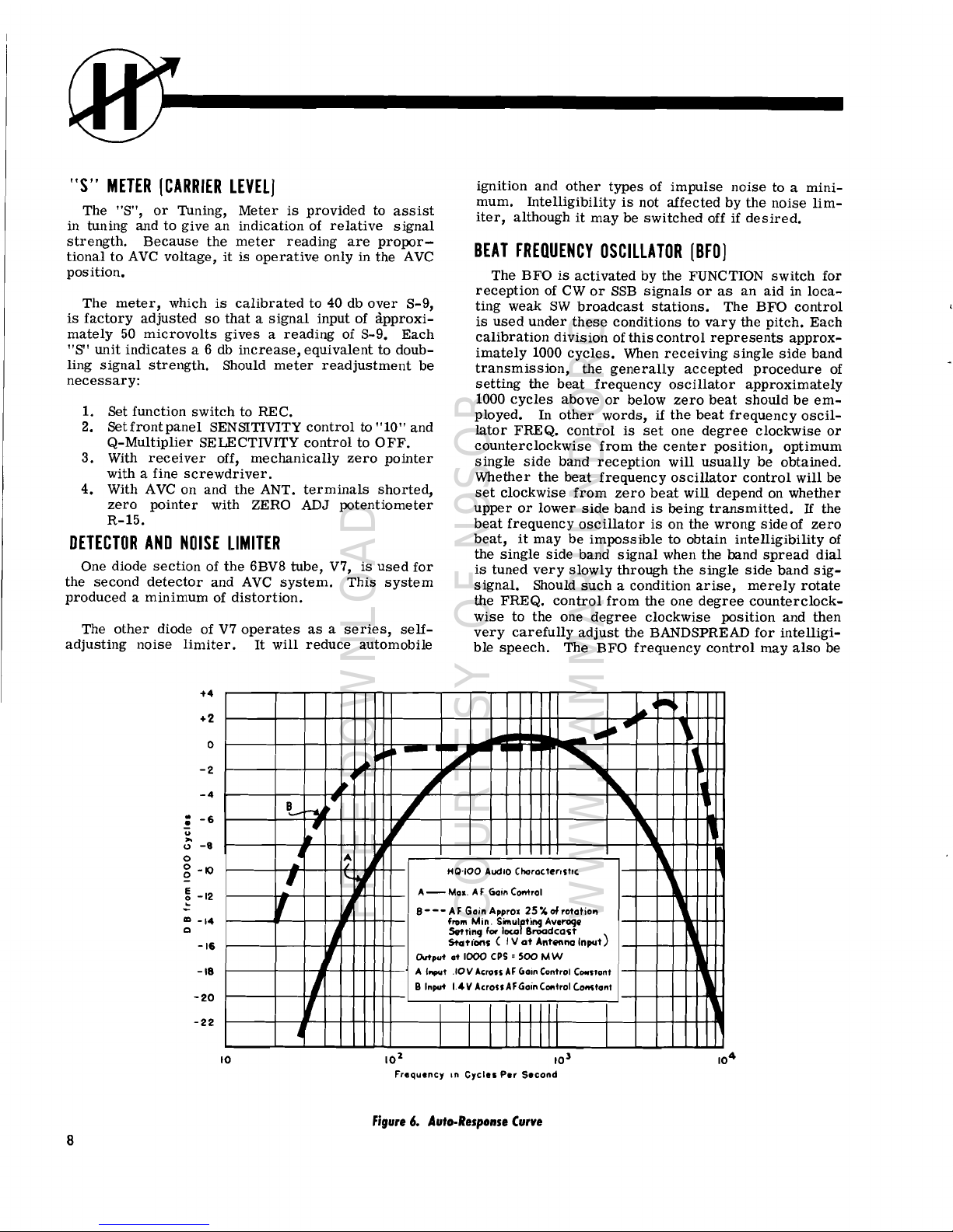
A
new
audio
output
circuit
feature
is
the
Auto-Response
which
auto-
matically
narrows
and
widens
the
frequency
range
of
the
audio
output,
depending
upon
the
gain
required.
This
feature
permits
the
receiver
to
be
used
as a high-fidelity
receiver
on
stronger
signals,
while
pro-
viding
the
sharp
cutoff
required
in
receiving
communication
b"gnals.
A
second
advantage
of
the
Hammarlund
Auto-Response
is
the
rapid
damping
of
the
audio
power
in
the
speaker
voice
coil
which
greatly
min-
imizes
undesirable
speaker
"hangover."
The
receiver
may
be
used
with
eithe r speaker
or
headphone
s.
Fast
acting
AVC
maintains a constant
audio
leveL
Adequate
filtering
practically
eliminates
AC
power
ripple.
The
HQ-lOOA
is
equipped
with a stable
beatfrequency
oscillator
which
provides
the
operator
with a continuous
range
of
audio
tones
when
re-
cei
ving
telegraph
code
signals,
or
excellent
single -side
band
reception.
An
"S"
meter
is
provided
to
obtain
accurate
reading
on
received
phone
signals
and
to
assure
"on-the-nose"
tuning.
A
send-receive
switch
is
provided
to
silence
the
receiver
while
transmitting.
Large,
comfortable
controls
in
logical
groupings
are
provided
for
greate
st
operating
ease.
The
new
futuristic
front
panel
is
clearly
marked
to
permit
full
attention
to
the
operating
at
hand.
The
HQ-lOOA
was
designed
with
you
in
mind.
You'll
have
many
hours
of
pleasure
and
use
in
operating
this
truly
fine
communications
instrument.
1
FREE DOWNLOAD
COURTESY OF N9SOR
WWW.HAMMARLUND.ORG

RECEIVER
figure
2.
Installation
of
Single-wire
Antenna
300
OHM
TV
TWIN LEAD
RECEIVER
figure
3.
Installation
of
folded
Dipole
Antenna
2
FREE DOWNLOAD
COURTESY OF N9SOR
WWW.HAMMARLUND.ORG
INSTALLATION
UNPACKING
Unpack
the
receiver
carefully.
Make
sure
the
tubes,
associated
tube
shields
and
pilot
lamps
are
in
place.
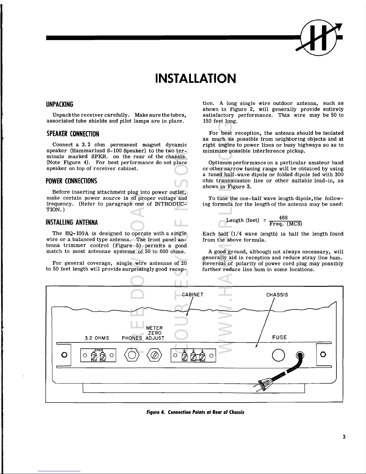
SPEAKER
CONNECriON
Connect a 3.2
ohm
permanent
magnet
dynamic
speaker
(Hammar
lund
S-100
Speaker)
to
the
two
ter-
minals
marked
SPKR.
on
the
rear
of
the
chassis.
(Note
Figure
4).
For
best
performance
do not
place
speaker
on
top
of
receiver
cabinet.
POWER
CONNEUIONS
Before
inserting
attachment
plug into
power
outlet,
make
certain
power
source
is
of
proper
voltage
and
frequency.
(Refer
to
paragraph
one of INTRODUC-
TION. )
INSTALLING
ANTENNA
The
HQ-100A
is
designed
to
operate
with a
single
wire
or a balanced
type
antenna.
The
front
panel
an-
tenna
trimmer
control
(Figure
5)
permits
a good
match
to
most
antennae
systems
of 50
to
600
ohms.
For
general
coverage,
single
wire
antennae
of 20
to
50
feet
length
will
provide
surprisingly
good
recep-
tion.
A long
single
wire
outdoor
antenna,
such
as
shown
in
Figure
2,
will
generally
provide
entirely
satisfactory
performance.
This
wire
may
be
50
to
150
feet
long.
For
best
reception,
the
antenna
should
be
isolated
as
much
as
possible
from
neighboring
objects
and
at
right
angles
to
power
lines
or
busy
highways
so
as
to
minimize
possible
interference
pickup.
Optimum
performance
on a
particular
amateur
band
or
other
narrow
tuning
range
will
be
obtained
by
using
a
tuned
half-wave
dipole
or
folded
dipole
fed with 300
ohm
transmission
line
or
other
suitable
lead-in,
as
shown
in
Figure
3.
To
tune
the
one-half
wave
length
dipole,
the
follow-
ing
formula
for
the
length
of
the
antenna
may
be
used:
Length
(feet) =
Fre~~8(MCS)
Each
half
(1/4
wave length)
is
half
the
length
found
from
the
above
formula.
A good
ground,
although
not
always
necessary,
will
generally
aid
in
reception
and
reduce
stray
line
hum.
Reversal
of
polarity
of
power
cord
plug
may
possibly
further
reduce
line hum in
some
locations.
CABINET
CHASSIS
o
METER
ZERO
3.2
OHMS PHONES ADJUST
o
o
figure
4.
Connection
Points
at
Rear
of
Chassis
3
FREE DOWNLOAD
COURTESY OF N9SOR
WWW.HAMMARLUND.ORG

®--------------
17
1
2
3
INDEX
NO.
1
2
3
4
5
6
7
8
INDEX
CONTROL
NO.
Automatic
Clock-Timer
Control
9
Function
Switch
10
ANTENNA
Trimmer
11
MAIN TUNING
Control
12
SENSITIVITY
Control
13
MAN.
-AVC
Switch
14
Band
Selector
Switch
15
Noise
Limiter
Switch
16
17
Figure
5.
location
of
Controls
CONTROL
AUDIO GAIN
Control
Electrical
BAND
SPREAD
Control
SELECTIVITY
Control,
Q -
Multiplier
Frequency
Control,
Q -
Multiplier
"S"
Meter
Electrical
Band
Spread
Dial
BFO
Frequency
Control
Main
Tuning
Dial
Telechron
Automatic
Clock-Time.
j
I
I
I
.'
4
FREE DOWNLOAD
COURTESY OF N9SOR
WWW.HAMMARLUND.ORG
OPERATION
Basically,
all
that
is
necessary
to
operate a radio
receiver
are
the
tuning
and
volume
controls.
The
addi-
tional
controls
found
on
the
front
panel
of a communica-
tions
receiver
such
as
the
HQ-100A,
control
functions
which
greatly
improve
operating
performance
and
make
possible
reception
of
oth~rwise
unintelligible
signals.
NORMAL
CONTROL
SETTINGS
For
"normal"
operation
such
as
broadcast,
short
wave
listening,
etc
.•
the
position
of
the
various
con-
trols
should
be
as
follows:
Function
Switch
. .
·
Receive
(REC.)
ANTENNA
Trimmer
·
Tune
for
highest
"S"
meter
reading
on
sig-
nal.
MAIN TUNING
Control
. . .
Tune
for
highest
"S"
meter
reading
on
sig-
nal.
SENSITIVITY
Control
·
Fully
clockwise
MAN. -AVC
Switch.
.
· AVC
Band
Selector
(TUNING.
·
Set
to
desired
frequen-
RANGE MCS)
Switch
cy
range.
Noise
Limiter
Switch
·
OFF
AUDIO GAIN
Control.
·
Adjust
for
proper
lev-
el.
BAND
SPREAD
Control.
·
Set
counterclockwise
to
"100"
on
band
spread
dial.
SELECTIVITY
Control
. . .
OFF
Frequency
(FREQ. ) Control . Set
pointer
to
trian-
gular
marking.
CODE
SIGNAL
RECEPTION
For
reception
of
code
signals,
the
controls
should
be
set
as
follows:
Function
Switch
. .
·
BFO
ANTENNA
Trimmer
·
Peak
for
maximum
out-
put
on
"S"
meter.
MAIN TUNING
Control
·
Peak
for
maximum
out-
put
on
"S"
,meter.
SENSITIVITY
Control
Adjust
for
desired
out-
put
level.
MAN. -AVC
Switch
.
Manual
(MAN.)
Band
Selector
(TUNING
Set
to
desired
frequen-
RANGE MCS)
Switch
cy
range.
Noise
Limiter
Switch
.
OFF
or
ON
as
required
by
local
noise
condi-
tions.
AUDIO GAIN
Control
.
2/3
to
3/4
clockwise
ro-
tation.
SELECTIVITY
Control
ON
position
BFO
FREQ
Control.
Tune
signal
to
zerobeat
with
pointer
on
zero
and
then
offset
either
left
or
right
for
des
ired
pitch.
FUNUION
SWITCH
Three
operating
and
an
OFF
position
are
provided.
For
AM
reception
the
REC
position
is
used.
CW
or
SSB
signals
may
be
received
with
the
FUNCTION
switch
on
BFO.
If
the
receiver
is
used
with a trans-
mitter
the
switch
should
be
in the SEND
position.
SINGLE
SIDE
BAND
OPERATION
The
setting
of
the
controls
for
Single Side
Band
reception
is
the
same
as
for
CW
reception
with
the
BFO
being
used
for
carrier
reinsertion.
The
BFO
fre-
quency
control
should
be
set
approximately
2-1/2
divisions
to
the
left
or
right
of
the
zero
indice,
de-
pending
upon
whether
the
upper
or
lower
sideband
intelligence
is
desired.
Final
tuning
should
be
accom-
plished
with
the
BAND
SPREAD
control
in
order
that
proper
speech
registry
be
achieved.
BAND
SPREAD
OPERATION
The
BAND
SPREAD
control
may
be
used
for
fine
tun-
ing
by Betting
it
at
apprOXimately gO'on
the
band
spread
5
FREE DOWNLOAD
COURTESY OF N9SOR
WWW.HAMMARLUND.ORG

m
dial
and tuning in the
signal
with
the
MAIN
TUNING
control.
Final
peaking of
the
signal
is
then
accom-
plished
by
adjustment
of the BAND SPREAD
control.
It
should
be
understood
that
the
setting
of
the
BAND
SPREAD
control
will
affect
the Main
Dial
calibration
in
that a higher
frequency
setting
of
the
main
tuning
dial
will
be
required.
Rotating
the
band
spread
dial
from
100
toward 0 tunes
the
receiver
to a lower
frequency.
For
Band
Spread
operation
in the
amateur
bands,
the
following
procedure
must
be
followed:
The
main
tuning
dial
is
set
to
the
line
marking
the
high
frequency
(right-
hand end) of a
given
amateur
band.
The
Band
Spread
tuning and
calibration
may
then
be
accomplished
solely
with
the
BAND SPREAD
control
and
dial.
20BS
SWITCH
POSITION
A
separate
switch
position
is
provided
on
the
TUNING RANGE
control
for
spreading
the
20-meter
band.
This
switches
in
another
band
spread
capacitor
for
optimum
spreading
of
this
band.
TElECHRON
AUTOMATIC
TIMER
If
your
receiver
is
equipped
with the
built-in
24
hour
Telechron
Automatic
Clock-Timer,
the
following
instructions
should be
noted:
Every
radio-frequency
device
is
stable
only
at
pre-
determined
operating
temperatures.
In
order
to
elim-
in
ate
waiting
for
receiver
to
warm-up
to
operating
temperature,'
the
Telechron'Timer
automatically
turns
on the
receiver
ahead
of
anticipated
operating
time.
This
is
accomplished
by
setting
the hand of the
timer
(small
knob
at
rear
of
receiver)
to
approximately
one-
half
hour
before
operating
hour.
The
front
panel
con-
trol
under
Timer
is
then
set
to
"Auto"
position.
The
function
switch
is
set
to REC. The
receiver
is
then
automatically
turned
on
at
the
desired
time.
The
clock
hands
are
set
by
the
rear
knob.
Push
in
on
the
knob to
set
the
switch
timing
hand and
pull
out
on the knob to
set
the
clock
hands.
The
front
switch
is
setto
AUTO and
the
operation
switch
is
set
to REC.
when
it
is
desired
to
use
the
automatic
clock
switch
for
pre-warming
the
receiver
before
operation
or
for
use
as
an
alarm
to
turn
the
receiver
on to a
pre-tuned
station.
To
use
the
operation
switch
normally,
the
clock
switch
should
be
left
in
the
ON
position.
The
clock
will continue to
run
as
long
as
the
receiver
line
cord
is
connected
to
the
power
outlet,
and
is
ex-
tremelyusefulfor
checking
sign-in
periods
and
sched-
ules.
If
your
receiver
is
not equipped with the
Telechron
Automatic
Clock-Timer,
and you would
care
to
have the
accessory
added,
clock
kits,
with
full
installation
instructions.
may
be
had
by
writing
Harnmarlund
Manufacturing
Co.
73-88
Harnrnarlund
Drive,
Mars
Hill,
North
Carolina
or
by
contacting
the
nearest
Harnrnarlund
dealer.
POSSI
BlE
RECEIVER
01
FFI
(Ul
TI
ES
1.
If,
upon
turning
the
function
switch
from
"off"
distortion
is
preferable
to
excessive
pulse
type
to
"receive"
position,
the
dials
are
not
illumi-
noise,
such
as
ignition
interference.
nated
and
the
receiver
fails
to
operate
after
two
minutes,
this
indicates
that
the
clock
timer
3.
Erratic S meter
performance,
lack
of
sufficient
switch
just
above
the
function
switch
is
nat·in
variation,
etc.,
is
usually
due
to
the
two 6BA6
the
proper
position.
This
switch
should
always
tubes
employed
in
the S meter
circuit.
These
be
in the
ON
position
unless
auto
timer
is
em-
are
the
tw06BA6tubes,
V5 and V6, in
the
sche-
ployed.
matic
diagram.
Merely
interchanging
these
tubes
will
sometimes
provide
sufficient
im-
provement.
Replacing
one
or
both
may
be
found
2.
Excessive
hum
or
failure
of
the
Qmultiplier
to
advisable
before
suspecting
other
troubles.
operate
properly
will
usually
be
due to a
de-
fective
12AX7
type
tube.
Such a
defective
tube
4.
Excessive
drift,
after
allowing
sufficient
time
may
test
good in a
tube
tester
but
be
unsatis-
for
warm
up,
may
be
due
to a poor
type
6C4
factory
because
of
higher
than
normal
heater-
tube, V3, in
the
diagram
or
6BE6, V2,
in
the
to-cathode
leakage.
Poor
noise
limiter
action
schematic
diagram.
is
usually
due
to a poor
or
defective
6BV8
type
tube.
The
use ofthe
noise
limiter
will
result
in
Ninety-nine
percent
of
all
receiver
trouble
has
been
some
distortion
which
must
be
tolerated
for
found
to
be
due
to
one
or
more
defective
tubes.
This
most
efficient
noise
limiting.
Because
of
this"
can
undoubtedly b e
attributed
to
the
rough
handling
when
listening
to
broadcast
stations
or
oth'er
equipments
receive
in
shipment.
Please,
therefore,
strong
local
signals,
the
noise
limiter
switch
be
sure
to
follow
the
above
suggestions
in addition to
should
be
in
the
"off"
position
unless
the
slight
haVing
all
tubes
tested
before
writing
the
Home Office.
6
FREE DOWNLOAD
COURTESY OF N9SOR
WWW.HAMMARLUND.ORG
CIRCUIT
THEORY
The HQ-100A
basically a single
conversion,
four-
band,
superheterodyne
receiver
with a noise
limiter
.Its
circuitry
incorporates a Q-Multiplier
for
full
control
of
selectivity
and a
stable,
beat
frequency
oscillator.
PRESELEGION
The
antenna
input
coupling and
RF
amplifier
stage
provide
the
necessary
preselection
and
gain
for
high
performance
and
rejection
of
undesired
signals.
The
high
signal
level
at
the
mixer
grid,
V2,
contributes
to a favorable
signal-to-noise
ratio.
Both
grid
and
plate
circuits
of
the
RF
stage
are
tuned;
individual
tuning
coils
are
selected
for
each
band.
The
antenna
compensating
compacitor,
adjustable
from
the
front
panel,
permits
the
receiver
to
be
resonated
for
optimum
performance
with
the
par-
ticular
antenna
in
use.
CONVERTER
STAGE
A high
degree
of
oscillator
stability
is
attained
by
the
use
of a
separate
mixer
(6BE6), V2,
and
an
inde-
pendent
oscillator
(6C4), V3.
The
output
signal
from
RF
amplifier
Vl
is
heter-
odyned with
the
output of
the
local
high
frequency
oscillator,
V3,
and
electronically
combined
within
the
mixer
tube,
V2,. On
the
four
frequency
ranges
the
local
oscillator
is
455
KCS
above
the
signal
fre-
quency.
Low-loss
tube
sockets,
low-loss,
phenolic
temper-
ature
compensating
capacitors,
and
stable,
coaxial
trimmers
all
contribute
to
oscillator
stability.
Addi-
tional
frequency
stability
is
attained
by
applying
regu-
lated
voltage
to
the
oscillator
circuit
and
by
the
rugged
construction
of
the
entire
HF
oscillator
section
as-
sembly.
Q
MULTIPLIER
The
Q-Multiplier
frequency
control
prOVides a
means
of
peaking
any
signal
within the
pass
band
of
the
IF
amplifier.
The
degree
of
peaking
is
controlled
by the SELECTIVITY
control.
This
same
SELECTI-
VITY
control
when
turned
completely
counter-clock-
wise
disconnects
the
Q-Multiplier.
If
interference
is
experienced,
either
between
sta-
tions
close
to one
another
or
from
an
interfering
SW
signal,
gradually
advance
the
Q-Multiplier
selectivity
control
from
its
normally
off
or
extreme
counterclock-
wise
position.
This
will
result
in
increased
selecti-
vity
by
producing a spike
of
narrow
bandwith
that
is
adjustable
from
approximately 3 KCS
to 100
cycles
in width. The
narrowest
bandwith
being
obtained
by
adjustment
of
the
Q-Multiplier
selectivity
control
to
the
point
just
below
that
which would
cause
the
Q-Multiplier
to
break
into
self-oscillation
as
evi-
denced
by
the
receiver
blocking with a
resultant
loss
of
volume.
The
Q-Multiplier
is
generally
never
employed
on
the
standard
broadcast
band
or
when
short
wave
broadcast
stations
are
being
received.
The
use
of
the
Q-Multiplier
under
these
circumstances
will only
result
in
limiting
the
frequency
response
of the
broad-
cast
band and
short
wave
broadcast
stations
in view
of
the
very
narrow
band width
that
is
provided
by
the
Q-Multiplier.
Of
course,
the
SELECTIVITY
control
will
make
it
possible
to
control
this
response
charac-
teristic.
If,
by
chance,
when
receiving
foreign
short
wave
broadcast
stations
interference
is
experienced
caused
by two
stations
operating
very
close
to
one
another,
the
Q-Multiplier
maybe
employed
under
these
circumstances
to
minimize,
if
not
eliminate,
the
inter-
ference
by
the
improved
selectiVity
or
decreased
band
width
proper
adjustment
will
provide.
The
proper
use
of
the
Q-Multiplier
can
actually
enhance
many
times
the
result
obtained with
this
receiver.
In
view of this"
it
is
suggested
that a little
time
be
spent
in
learning
just
how
to
properly
adjust
the
Q-Multiplier
frequency
and
selectivity
controls
under
different
receiving
condi-
tions.
As
the
Q-Multiplier
SELECTIVITY
control
is
advanced, a
decided
decrease
in
noise
will
be
ap-
parent.
This
is
due
to
the
narrowing
of
the
pass
band.
On
AM
phone
signals
this
control
will
usually
be
be-
tween
the 7 and
11
o'clock
positions.
The
FREQUEN-
CY
control
should
then
be
adjusted
for
clarity
of
sig-
nal
or
for
minimum
adjacent
channel
interference.
The
SELECTIVITY
control
may
be
advanced
progres-
sively
more
for
SSB and
CW
reception.
The
more
this
c·ontrol
is
advanced,
the
more
critical
the
setting
of
the
FREQUENCY
control
becomes.
Advancing
the
SELECTIVITY
control
too
far
will
cause
the
Q-Multi-
plier
to
oscillate.
This
should
be
avoided.
The
Q-
Multiplier
is a very
handy
tool
in
the
hands
of
an
experienced
operator
and,
unfortunately,
it
is
beyond
the
scope
of
this
instruction
manual
to
attempt
to
be
more
definite
than
we
have.
IF
AMPLIFIER
Seven,
stable
tuned
circuits,
in two
stages
of
IF
amplification
(V5
and
V6),
contribute
to
sensitivity
and
selectivity.
Iron
core
permeability-tuned
trans-
formers
improve
performance
and add
to
the
ease
of
adjustment.
The
intermediate
frequency
is
455 KCS,
the EIA
standard.
Ave
SYSTEM
Automatic Volume
Control
minimizes
fading and
signal
strength
variations
by
controlling
the
gain of
the
RF
stage
Vl
and
the
IF
stage
V5.
As
a
result,
a
comfortable
and
constant
level
of audio
is
maintained.
7
FREE DOWNLOAD
COURTESY OF N9SOR
WWW.HAMMARLUND.ORG
"S"
METER
ICARRIER
LEVEl]
The "S",
or
Tuning,
Meter
is
provided
to
assist
in tuning and
to
give
an
indication of
relative
signal
strength.
Because
the
meter
reading
are
propor-
tional
to
AVC
voltage,
it
is
operative
only
in the
AVC
position.
The
meter,
which
is
calibrated
to 40 db
over
S-9,
is
factory
adjusted
so
that a signal
input of
approxi-
mately
50
microvolts
gives a reading
of S-9.
Each
"S"
unit
indicates
a 6 db
increase,
eqUivalent to
doub-
ling
signal
strength.
Should
meter
readjustment
be
necessary:
L Set function
switch
to REC.
2.
Set
front
panel
SENSITIVITY
control
to
"10"
and
Q-Multiplier
SELECTIVITY
control
to
OFF.
3.
With
receiver
off,
mechanically
zero
pointer
with a fine
screwdriver.
4.
With A
VC
on and
the
ANT.
terminals
shorted,
zero
pointer
with ZERO ADJ
potentiometer
R-15.
DETECTOR
AND
NOISE
LIMITER
One diode
section
of
the
6BV8 tube, V7,
is
used
for
the
second
detector
and
AVC
system.
This
system
produced a minimum
of
distortion.
The
other
diode of
V7
operates
as a series,
self-
adjusting
noise
limiter.
It
will
reduce
automobile
+4
+2
0
-2
-4
•
-6
~
u
...
<J
-9
0
g
-10
~
-12
~
lD
-14
0
-16
-18
-20
-22
ignition and
other
types
of
impulse
noise
to a mll1l-
mum.
Intelligibility
is
not
affected
by
the
noise
lim-
iter,
although
it
may
be
switched
off if
desired.
BEAT
FREQUENCY
OSCILLATOR
IBFO]
The
BFO
is
activated
by the FUNCTION
switch
for
reception
of CW
or
SSB
signals
or
as
an
aid
in
loca-
ting
weak
SW
broadcast
stations.
The
BFO
control
is
used
under
these
conditions
to
vary
the
pitch.
Each
calibration
diVision of
this
control
represents
approx-
imately
1000
cycles.
When
receiving
single
side
band
transmission,
the
generally
accepted
procedure
of
setting
the
beat
frequency
oscillator
approximately
1000
cycles
above
or
below
zero
beat
should
be
em-
ployed. In
other
words,
if
the
beat
frequency
oscil-
lator
FREQ.
control
is
set
one
degree
clockwise
or
counterclockwise
from
the
center
position,
optimum
single
side
band
reception
will
usually
be
obtained.
Whether
the
beat
frequency
oscillator
control
will
be
set
clockwise
from
zero
beat
will depend on
whether
upper
or
lower
side
band
is
being
transmitted.
If
the
beat
frequency
oscillator
is
on
the
wrong
side
of
zero
beat,
it
may
be
impossible
to obtain
intelligibility
of
the
single
side
band
signal
when
the
band
spread
dial
is
tuned
very
slowly
through
the
single
Side band
sig-
signal.
Should
such
a condition
arise,
merely
rotate
the FREQ.
control
from
the
one
degree
counterclock-
wise
to the one
degree
clockwise
position
and
then
very
carefully
adjust
the BANDSPREAD
for
intelligi-
ble
speech.
The
BFO
frequency
control
may
also
be
16
1
IIIIl
--
,-.
~
J
-
~
,..
...
"'
I'
,
~P"
~
,
L
-.....
..-
/
,
.~
"
I'
..4
A
~
~
,
I
....
~
HQ'IOO AudiO
Chara"er'lt"
\.
A -
Ma
•. A F Gain Comrol
I(
~
8 - - - AF Gain Appro.
2S
~
of
r.tali."
I~
fro
..
Min. Simulrting
Averaq41
IJ
Settin9
for
11><0
8roadcal;t
~
StcItiont
( IV
at
A"t4lll"a
In""t
)
,
Output
.,1000
CPS'
500
MW
~
I
A
I_t
.10 V
A,rou
AF
Cla,n
Control
Cow
..
ont
B Input 1.4V
A"auAFGoinC
...
lrol
C.OIl1OIo"I
,
~
10
10
1
10)
Frequency
,n
Cycles
Per
Second
figure
6.
Auto-Response
Cur"e
8
FREE DOWNLOAD
COURTESY OF N9SOR
WWW.HAMMARLUND.ORG

----------------@
employed
as
a fine
tuning
adjustment
to
obtain
desired
speech
quality.
Here
again
experience
is
the
best
teacher.
The
stability
of
both
the
high
frequency
os-
cillator
and
the
beat
frequency
oscillator
employed
in
this
receiver
plus
the
excellent
mechanical
rigi-
dity
will
prOVide
excellent
single
side
band
reception.
Refer
to
the
paragraph
on the
Q-Multiplier
operation
for
increase
selectivity
or
narrowing
of
the
passband
usually
permissable
with
CW
and
sideband
reception.
It
may
be
found
desirable
to
place
the
function
switch
on
BFa
while
tuning
to
aide
in
locating
weak
signals.
As a
result
of
activating
the
BFO,
each
carrier
tuned
in
will
produce a beat
note
or
whistle
easily
discern-
able.
If
a phone
signal
is
located
in
this
manner,
adjust
the
bands
pre
ad
tuning
control
for
the
lower
pitch
tone
or
zero
beat.
This
will
result
in
centering
the
desired
phone
signal
and
now
placing
the
function
switch
on
REC
will
allow
for
normal
AM
operation.
AUDIO
AMPI.IFIER
The
first
audio
stage
is a resistance
coupled
voltage
amplifier
employing
the
other
section
of
the
l2AX7
(V4B).
The
audio
output
stage
is
a 6AQ5
beam
power
amplifier
(V8) prOViding
an
undistorted
output
level
of
at
least
one
watt.
A
feature
ofthe
audio
system
is
the
variable
negative
feedback
employed
(see
Auto-Response
Curve,
Figure
6).
Maximum
feedback
is
provided
at
low
settings
of
the
AUDIO GAIN
control
for
the
fine
quality
reception
of
local
broadcast
and
strong
short
wave
stations.
As
the
AUDIO GAIN
control
is
increased,
the
feedback
decreases
so
that
on
reception
of
weak
signals
addi-
tional
selectivity
is
prOVided by
the
audio
section.
This
results
in
an
increased
signal-to-noise
ratio. A further
advantage
is
the
critical
damping
of
the
speaker
for
elimination
of
speaker
"hangover".
This
upgrades
the
reception
of
speech
and
music
and
decreases
the
noise
output of
the
receiver.
A
further
advantage
is
the
reduction
of
distortion
at
lower
settings
of
the
AUDIO GAIN
control.
ACCESSORIES
A
Now you
can
get
even
more
out
of
your
HQ-lOOA
This
is
not
usually
required
by
the
average
short
receiver!
wave
listener,
although
it
will
prove
an
aid
as a means
of
correcting
for
possible
dial
error.
The
amateur
operator
will
find
this
of
most
value
The
XC-lOO
Crystal
Calibrator
is
available,
pro-
since
the
100
KCS
checkpoints
this
unit
provides,
will
viding
checkpoints
every
100 KCs
within
the
range
of
make
it
possible
to
accurately
set
amateur
band
edges.
the
receiver.
This
will
result
in
improving
the
accuracy
of
the
am-
ateur
band
spread
dial,
by
determining
the
exact
set-
ting
of
the
main
tuning
dial.
The
kit
is
qUickly
and
easily
installed.
It
is
com-
plete
with
eas
y-to-follow
instructions
,operating
switch
and
mounting
hardware.
9
FREE DOWNLOAD
COURTESY OF N9SOR
WWW.HAMMARLUND.ORG

®--------------
SERVICE
AND
REALIGNMENT
PROCEDURE
NOTE
To
service
this
receiver,
disconnect
from
power
source
and
remove
all
leadwires
attached
to
terminal
connections
at
rear
of
chassis
apron.
Carefully
turn
the
receiver
up onto
the
front
panel
face
on a
smooth
clean
surf~ce.
Remove
the
two #10 hex
machine
screws
at
the
extreme
ends
of
the
chassis
apron
at
the
rear
of
the
cabinet,
and the knob
from
the
clock
adjustment
shaft ifreceiver
is
so
equipped.
Lift
cabinet
straight
up
and
off of
chassis.
To
reassemble,
use
reverse
procedure.
ANTENNA
ADJUSTME.II.IS
/ ADJUST
SUJG
AT
4MC ADJUST
SWG
AT
1.2
M.C
ADJUST
SLUG AT
L65
Me
ADJUST
SWG
AT IOMC \
WITH
ANT.
CAPACITOR
WITH
ANT.
CAPACITOR
WITH
ANT. CAPACITOR
WITH
ANT.
CAPACITOR
NEAR
MID. CAPACITY
NEAR
M I
N.CAPACITY
NEAR
MID. CAPACITY
NEAR
MID
CAPACITY
•
IF
ADJUSTMENTS
TOP
SLUG
ADJUST
AT
AT
1.65
MC
FOR MAX.
AT
4MC
BOTTOM
BOTTOM
SLUG
ADJUST
TOP
SWG
ADJUST
4MC
BOTTOM
SLUG
AMPLITUDE
SWG
ADJUST AT
TOP
SLUG
ADJUST
AT
ADJUST
AT
10
MC
10
MC
.6MC
BOTTOM
SLUG
\.\...
-J/
'\
ADJUST AT
1.65MC
R F
ADJUSTMENTS
H F
OSc.
ADJUSTMENTS
figure
7.
)'op
View
of
Chassis
I
10
FREE DOWNLOAD
COURTESY OF N9SOR
WWW.HAMMARLUND.ORG

IF
ALIGNMENT
NOTE
Use a non-
metallic
alignment
tool
such
as
Gen-
eral
Cement
Co. No. 5097,
or
equal.
a.
Connect
the
output
cable
of a 455 KCS
unmodu-
lated.
signal
generator
to
the
bus
lead
of
the
6BE6
mixer
gnd.
The
frequency
accuracy
of
the
generator
may
be
checked
with
sufficient
precision
by
picking
up
its
second
harmonic
(910 KCS)
in
any
receiver
whose
calibration
at
910 KCS
has
been
checked
as
correct
and
then
adjusting
the
generator
frequency.
b.
Connect
aDC
vacuum
tube
voltmeter,
set
for
neg-
ati
ve
voltage
reading
to
pin S of
the
V7, 6BVS
socket.
c.
Set
the
receiver
controls
as
follows:
BAND
SPREAD
dial
on 100
Function
switch
on
REC.
Main
tuning
dial
on
. 54
MC
Noise
limiter
switch
on
OFF
AUDIO GAIN
control
at
minimum
SELECTIVITY
control
on
OFF
Band
selector
switch
on . 54 - 1. 6 MC
MAN.
-AVe
switch
on MAN.
SENSITIVITY
control
on 3
from
maximum.
d.
During
alignment,
adjust
the
generator
output
and
the
SENSITIVITY
control
to
prevent
over-
loading.
Final
adjustment
should
be
made
with
the
SENSITIVITY
control
at
approximately
the
third
indice
from
its
maximum
(clockwise)
posi-
tion.
Adjust
each
of
the
three
IF
transformers
fo,('
maximum
meter
reading.
Topside
adjust-
ments
(Figure
7)
are
secondaries
or
grid
cir-
figure
B.
Bottom
View
of
Chassis
11
FREE DOWNLOAD
COURTESY OF N9SOR
WWW.HAMMARLUND.ORG

@--------------
cuits;
bottom
of
chassis
adjustments
(Figure
8)
are
primaries
or
plate
circuits.
e.
Turn
the
Q-MULTI.
ON
and
adjust
the
SELEC-
TIVITY
control
clockwise
to a
position
below
the
oscillating
point.
With
its
panel
bushing
nut
loosened
to
permit
the
frequency
shaft
to
turn
without
hindrance
by
the
stop,
adjust
the
FREQ.
control
to
obtain a maximum
meter
indication.
The
input
signal
must
be
adjusted
to a value
just
sufficient
to
obtain a good
meter
swing.
This
adjustment
is
the
center
frequency
of
the
pass
band.
While
the
meter
is
at
maximum,
turn
the
stop
lug to a
position
180
degrees
directly
opposite
the
stop
pin
in
the
frequency
shaft.
Holding
it
in
this
position,
tighten
the
bushing
in
the
nut
making
sure
that
the
shaft
or
the
stop
lug
have
not
turned bychecking
the
zero
setting.
f.
Turn
FUNCTION
switch
to
BFO.
With
the
BFO
frequency
control
on ZERO
adjust
the
slug
in
L7
for
ZERO
beat
with
the
AVC-MAN
switch
on
MAN
position
and
the
SENSITIVITY
control
adjusted
at a position
below
overload.
g.
With
the
MAN.
-AVCswitchon
AVC,
the
SENSI-
TIVITY
control
at
maximum,
with
grid
pin 1 of
the
V5
amplifier
tube
grounded,
and
with
no
signal
input,
adjust
the
METER
ZERO ADJUST.
pot
at
the
rear
of
the
chassis
(Figure
4)
for
a
reading
of
zero
on
the
"8"
meter.
RF
ALIGNMENT
NOTE
Use a non-metallic
alignment
tool
such
as
Gen-
eral
Cement
Co. No. 8282,
or
equal.
a.
The
slugs
and
trimmers,
having
been
factory
adjusted,
should
require a minimum
amount
of
adjustment
for
any
realignment.
b.
All
RF
and
oscillator
slug
adjustments
are
made
from
the
top
of
the
shield
cans.
See
Figure
7.
c.
Connect
the
unmodulated,
signal
generator
out-
put
cable
to
the
antenna
and
ground
terminals
of
the
receiver,
with
the A terminal
adjacent
to
the G terminal
jumped
together.
See
Figure
4.
d.
Set
the
controls
the
same
as
for
IF
alignment
above.
Adjust
the
SENSITIVITY
control
as
re-
quired
to
obtain a sufficient
voltmeter
read-
ing
and
to
prevent
overloading.
e.
The
oscillator
adjustment
is
made
first.
The
RF
is
adjusted
next
to
obtain
maximum
ampli-
tude.
The
antenna
slugs
are
adjusted
last.
A
certain
amount
of
interaction
will
occur
between
the
oscillator
and
RF
adjustments,
partiCUlarly
on
the
higher
frequency
bands.
Final
adjust-
ment
should
be
accomplished
by
combined
or
alternate
adjustment
of
the
oscillator
and
RF
for
maximum
amplitude.
NOTE
The
trimmer
adjustments,
if
required,
should
be
the
final
adjustment
for
each
band.
See
Fig-
ure 8 for
location
of
trimmers.
There
is
no
RF
amplifier
adjustment
for
the
. 54 - 1. 6 MCband.
f.
Note
that
the
oscillator
frequency
in
the
HQ-100
is
always
on
the
high
side
of
the
signal
frequency
by 455 MCS.
Therefore,
it
is
necessary
to
make
sure
that
the
oscillator
frequency
is
not
adjusted
below
the
signal
frequency
which
would
be
an
image
response
of
the
signal.
g.
It
will
be
necessary
to
repeat
low
and
high
end
alignment
adjustments
of
each
band
since
the
adjustments
are
interdependent.
The
process
should
be
repeated
until
maximum
amplitude
is
obtained
at
both
alignment
frequencies
of
each
band.
NOTE
The
receiver
should
be
warmed
up
at
least
one-half
hour
before
final
oscillator
frequency
adjustments
are
made
for
the
dial
calibration
check.
DIAL
CAI.IBRATION
a.
Use a crystal
calibrator
haVing 100
KCS
and
1000
KCS
output.
Set
the
arbitrary
band
spread
dial
scale
to
100.
Set
the
function
switch
to
BFO.
Set
the
BFO
FREQ.
control
to
zero.
Set
the
SELECTIVITY
control
toOFF.
Set
the
MAN.
-AVC
switch
to
MAN.
b.
Check
to
see
that
the
frequencies
at
or
near
the
alignment
frequencies
are
"on
the
line."
If
not,
make
minor
adjustments
of
the
slugs
and
trim-
mers
(Figures 7 and
8)
to
make
them
correct.
CAUTION
Weaker
signals
will
be
observed
at
dial
settings
apprOXimately 10 KC8
above
each
calibration
dial
marking.
These
are
image
signals
from
1
MC
above
the
desired
signal
and
may
be
re-
cognized
by
their
somewhat
weaker
strength
and
may
be
further
reduced
by
proper
adjust-
ment
of
the
gain
controls.
They
will,
of
course,
be
more
noticeable
on
the
higher
bands.
Keeping
the
antenna
tuned
will
help.
12
FREE DOWNLOAD
COURTESY OF N9SOR
WWW.HAMMARLUND.ORG

CI)
Cl
o
eX)
co
o
o
~
co
o
o
N
20
30
--.
,
II
, ,
--,
,
•
.
•
I
1\
,
\
j
I{
\
,
I I
\
\
IT
117
\
\ \
II
I
A-++\
,
\
..
C
I
1/
\
I
,
I
,
,
--.
--,
--,
,
--,
"
I!t
i
II
I~
\
\ I
II I
\'
\
I!
1'7
,
\
1\
\
I j
7
I
,
1\ \
T
"
,
-,
TT
\
\
,
.1
~\
\
,
/I
\'
\
,
,,'/
\
I
\
,
,
~
,
,
1\
I
,
l=
HO-IOO
Selectivity
,
l-
•
I'
I-
A
-Regular
if
" I
II
I-
6.0
KC
at
6 DB
,\
.
I j
I-
1\\
~
I 1
~
B-
-0
Mult.
Max.width
2.9
KCat6DB
h:
,,
r-
c----Q
Mutt. Adj'd
for
\\
,
I
I,
-
.3
KC
016
DB
~I
V
30
20
10
0 + 10
K C
off
Resonance
Figure
9.
Se'ectivity
Curves
13
FREE DOWNLOAD
COURTESY OF N9SOR
WWW.HAMMARLUND.ORG

:i;:
TABLE
1.
TUBE
SOCKET
VOLTAGES
MEASURED
FROM
TUBE
SOCKET
PINS
TO
CHASSIS WITH VTVM AUDIO GAIN MINIMUM. BAND SWITCH ON 10 TO 30
Me.
LIMITER
OFF.
AVC-MAN SWITCH ON MAN.
SENSITIVITY
MAX.
OPERATION
SWITCH ON
REC.
Q-MULTIPLIER
OFF.
LINE
VOLTAGE
117. NO SIGNAL
INPUT.
TUBE
SOCKET
PIN NUMBERS
SOCKET
NO.
1
2
3 4
5
6 7 8
9
V1RF
6BZ6
V2 MIXER
6BE6
V3
HFO
6C4
V4
12AX7
Q
MULT.
1st
A-F
V5
1st
IF
6BA6
V6
2nd
IF
6BA6
V7 6BV8
DET
LIM AVC
BFO
VB
6AQ5
AUDIO
OUTPUT
V9
OA2
V-R
1.8
6.3
AC
210
105
-6
1.3
6.3
AC
205
70
90
6.3
AC
90
-3
TO
-9
90
1.5
60
6.3
AC
200
100
-8
BFO
ON 110
BFO
ON
6.3
AC
6.3
AC
200
1.2
AC
95
-.2
-9
BFO
ON
105
13
6.3
AC
105
210
205
FREE DOWNLOAD
COURTESY OF N9SOR
WWW.HAMMARLUND.ORG

TABLE
2.
TUBE
SOCKET
RESISTANCES
BAND
SWITCH
ON
10-30
MC.
MEASURED
FROM
TUBE
SOCKET
PINS
TO
CHASSIS. AUDIO GAIN MAXIMUM.
OPERATIONS
SWITCH
ON
REC.
BFO
OFF.
LIMITER
ON.
SENSITIVITY
MAXIMUM.
AVC-MAN
ON MAN.
TUBE
SOCKET
PIN
NUMBERS
SOCKET
NO.
-
1
2
3 4
5
6
7
8 9
VI
RF
10K
6BZ6
2.4M
ON AVC
180
0 0
.5
MEG
.5
MEG
0
V2
MIXER
6BE6
22K 180
0
0
.5
MEG
.5
MEG
0
V3
HFO
6C4
.5
MEG
INF
0 0
.5
MEG
47K
0
V412AX7
6800
Q
MULT.
1st
AF
.5
MEG
2.2
MEG
16KSEL
OFF
0 0
.5
MEG
1
MEG
2200
0
V5
1st
IF
0
180
6BA6
2.4M
ON AVC
0 0 0
.5
MEG
.5
MEG
10K
MIN
SENS
-
V6
2nd
IF
200
6BA6
470K
0 0
0
.5
MEG
.5
MEG
10K
MIN
SENS
-
V7
6BV8
DET
LIM
AVC
BFO
0
lOOK
.5
MEG
0
3.3
120 K
0
2.2
MEG
190 K
BFa
ON
lOOK
LIM
OFF
V86AQ5
AUDIO
OUTPUT
.5
MEG
430
0 0
.5
MEG
.5
MEG
.5
MEG
V9
OA2
V-R
.5
MEG
0
INF
0
.5
MEG
INF
0
.....
CJ1
FREE DOWNLOAD
COURTESY OF N9SOR
WWW.HAMMARLUND.ORG
m
Sche=atic
Designation
C1, Athru
C
C2, Athru
F
C3
C4,
5,
6,
7,8,9,10,
15,19,30,31,32,
34,35,36,41,48
Cll,
12,
13
C16,
17,
18
C20,21,22,23
C24
C25
C26,57
C27
C28
C29
C33,
45,
46
C38
C38A
C38B
C38C
C42
C43,44
C47
C49,50
C51
C52
C53
C54
C55
C56
C58
C59
C60
Ll
L2
L3
L4
L5
L6
L7
Rl,32
R2
R3
R4,
10
R5
R6,33
R8
R9,34
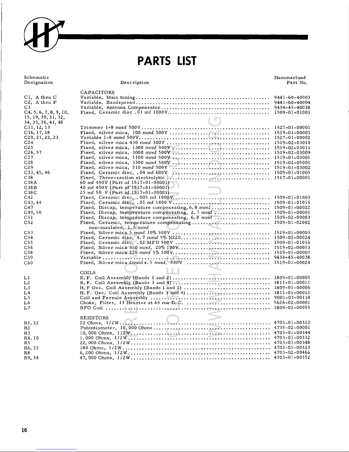
PARTS
LIST
Description
CAPACITORS
Variable,
Main
tuning
..•••.....•......•..•.•.....•.•.....•..•....•...
Variable,
Bandspread
..........•....•..............•.............••.•
Variable,
Antenna
Co=pensator
...•..•.•....•.......•.................
Fixed,
Ceramic
disc.
01
mf
1000V
.
Trimmer
1-8
mmf
500V
..........•.••.....•.•.......•..
"
......•..•..
Fixed,
silver
mica,
100
mmf
500V
...•.....•.••......•....•..•....•.•.
Variable
1-8
mmf
500V
...•...••...•...••....•••.•.•...•...
'
.••......•.
Fixed,
silver
mica
430
mmf
300V
...••......•.....•......•.••.•.•••...
Fixed,
silver
mica,
1300
mmf
500V
.....•...............•......•......
Fixed,
silver
mica,
3000
mrnf
500V
.....•...•••......•.......••...•...
Fixed,
silver
mica,
1100
mrnf
500V
..•....•.•...........•..•••...•••..
Fixed,
silver
mica,
3300
=mf
500V
..•....••.....••......•••........•.
Fixed,
silver
=ica,
510
=mf
500V
..•..................••......•••...
Fixed,
Ceramic
disc,
.04
mf
600V
.•...•••..•....•....•.......••....•
Fixed,
Three-section
electrolytic
....••.•••••.•.....•.......•...••••..
60
rnf
450V
(Part
of
1517-01-00001)
40
rnf
450V
(Part
of
1517-01-00001)
25
mf
50 V (Part
of
1517-01-00001)
Fixed,
Ceramic
disc,
.005
mf
1000V
....•......•......•..•.....•.•..•..
Fixed,
Ceramic
disc,
. 01
rnf
1400 V.........•••......•.....•.•..•.•...
Fixed,
Discap,
temperature
compensating,
6.8
mmf
............••..•....
Fixed,
Discap,
temperature
compensating,
2.7
=mf
.......•.....•....••
Fixed,
Discap,
te=perature
compensating,
6.8
mmf
..•..............•.•
Fixed,
Ceramic,
temperature
compensating
..••.
'"
...
'"
....•.•.•••...
non-insulated,
1,
5
mmf
Fixed,
Silver
mica 5 mmf
10%
500V
....•.....•......•.............•...
Fixed,
Ceramic
disc,
4.7
mmf
5%
N220
..•....
,.
.•....•.............•...
Fixed,
Ceramic
disc,
.02
MFD
500V
..•.•......•................••.••.
Fixed,
Silver
mica
350
mmf,
20%
100V
....•...••..........•............
Fixed,
Silver
mica
220
mmf
5%
500V
....•....••.......................•
Variable
....•......
'"
.••............•....•...........
"
•.....•.....
Fixed,
Silver
mica
2mrnf
±.
5
mmf,
500V
......•..•...••..••..•.••.•...
COILS
R.
F.
Coil
Assembly
(Bands 1 and
2)
........•..•.•......
,
...••......••.
R.
F.
Coil
Assembly
(Bands 3 and
4)
.....•.....••....
,
.•.•........••....
H. F Osc.
Coil
Assembly
(Bands 1 and
2)
...••••.......•....••.•....•.••
H.
F.
Osc.
Coil
Assembly
(Bands 3 and
4)
..•.•.••....••....•.•.•.••....
Coil
and
Ferrule
Assembly
..•......••...••.....•.............•.•.•••.
Choke,
Filter,
13
Henries
at
65
ma
D. C......••.•.•...•...•....•••....
BFO
Coil
.•...••.•.•......•...••.•.•..•..•.•.•..••........•••.••••••
RESISTORS
22
Ohms, 1/2W
.....•.•...........••.•.••..•......•.•......•.•.......
Potentiometer,
10,000
Ohms
.......•.........••.•..•....•..••...•.....
10,000
Ohms,
1/2W
...•...•....•.•...•.•..••...•.••.........•....•..•
1,000
Ohms,
1/2W
.••.........•.....••..••....••.•...•.....•...•.....
22,000
Ohms,
1/2W
.•....•..........•.....•...........•.........•..••
180
Ohms,
1/2W
.•...............•......•...•.........•.....•.....•..
6,200
Ohms, 1/2W
.•..•.•.........•....•..•.•..•..•....•...•.•..•....
47,000
Ohms,
1/2W
.................•..•••....•.........•.•••••..•.•.
Hammarlund
Part
No.
9441-60-40003
9441-60-40004
9434-45-40038
1509-01-01001
1527-01-00001
1519-01-00001
1527-01-00002
1519-02-03010
1519-02-03011
1519-02-03009
1519-01-03001
1519-02-05001
1519-01-03002
1509-01-01005
1517-01-00001
1509-01-01003
1509-01-01015
1509-01-00022
1509-01-00001
1509-02-00003
1509-01-02002
1519-01-00003
1509-02-00024
1509-01-01016
1519-02-00053
1519-01-00007
9434-45-40038
1519-01-00024
1809-01-00005
1811-01-00011
1809-01-00006
1811-01-00012
9001-03-00118
5626-02-00001
1804-02-00055
4703-01-00312
4735-02-00001
4703-01-00344
4703-01-00332
4703-01-00348
4703-01-00323
4703-02-00466
4703-01-00352
16
FREE DOWNLOAD
COURTESY OF N9SOR
WWW.HAMMARLUND.ORG
------------------@
Schematic
Designation
R11
R12
R13
R14,
16,
21, 29,
35
R15
R17
R19
R20
R27
R28
R30
R31
R36
R37
R38
R39
R40
SlA,
SIB
SIC
S2
S3
S4
S5
Tl
T2
T3
T4
T5,
6, 7
T8
T9
CRl,2
Fl
Fl
II,2
Jl
Ml
P2
P2
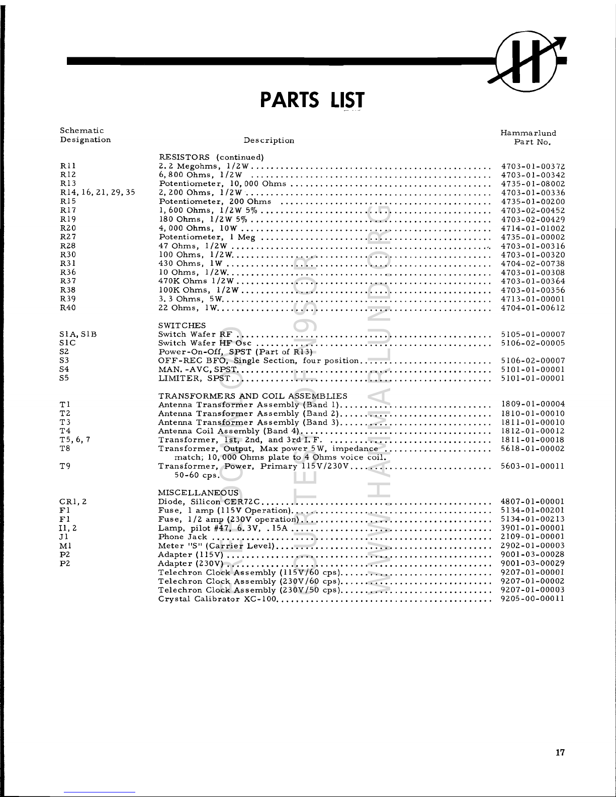
PARTS
LIST
Description
RESISTORS
(continued)
2.2
Megohms,
1/2W
.
6,8000hms,l/2W
.....•................•..........................
Potentiometer,
10,000
Ohms
.................•.......................
2,200
Ohms, 1/2W"
" .
Potentiometer,
200
Ohms
.....................•.....................
1,600
Ohms,
1/2W
5%
.••.....................•......................
180
Ohms,
1/2W
5%
.•...................•.................•.........
4,000
Ohms,
lOW
.
Potentiometer,
1
Meg
•..............................................
47
Ohms,
1/2W
..........................•.........................
'.
100
Ohms,
1/2W
............•...•....................................
430
Ohms,
1W
..........•...........................................
10
Ohms,
1/2W
.....••...........................................•...
470K
Ohms
1/2W
...•...............••.••.•....•.......•....•........
lOOK
Ohms,
1/2W
..........••.•••••..........•.................•...•
3.3
Ohms,
5W
........••....•.•......................................
22
Ohms,
1W
.....•.••.•.••...........................•.....•........
SWITCHES
Switch
Wafer
RF
.......•..................................•.•.•••...
Switch
Wafer
HF
Osc
.............•..•••....••.••......•.•...........
Power-On-Off,
SPST
(Part
of
R13)
OFF-REC
BFO,
Single
Section,
four
position
...•.•.....•••.•.••....•...
MAN.
-AVC,
SPST
...••••.••••..•......••.•..••••..•.•••••••••••.•....
LIMITER,
SPST
........•.•..•.............................••.•......
TRANSFORMERS
AND
COIL
ASSEMBLIES
Antenna
Transformer
Assembly
(Band 1).•..••••••..•.••.......•.•.....
Antenna
Transformer
Assembly
(Band
2)
..............................•
Antenna
Transformer
Assembly
(Band 3)......•........................
Antenna
Coil
Assembly
(Band
4)
..•••...•..............................
Transformer,
1st,
2nd,
and
3rd
1.
F.
..
.
Transformer,
Output,
Max
power
5W,
impedance
.
match;
10,000
Ohms
plate
to 4 Ohms
voice
coil.
Transformer,
Power,
Primary
115V
/230V
....................•.•.••.•.
50-60
cps.
MISCELLANEOUS
Diode,
Silicon
CER72C
.•........•••..........•..........•............
Fuse, 1 amp
(115V
Operation)
......••................•••.•.•..........
Fuse,
1/2
amp
(230V
operation)
..•••••.••.........•..•..•••.•••.•.....
Lamp,
pilot
#47,
6.3V, . 15A
.•......••.••......•..........••••••.....
Phone
Jack
..............•.•........•.•....................•..••.•..
Meter
"s"
(Carrier
Level)
...•..•••..••......••.•••...........•..•.•••
Adapter
(115V)
.•....•.•••••....•...••••......•.....•..•..••••......•
Adapter
(230V)
.......••••••..•..••••.•....•..•.•.....••••.........••
Telechron
Clock
Assembly
(115V/60
cps)
.••.•••..•..........•.•••••...•
Telechron
Clock
Assembly
(230V
/60
cps)
.•.................••.•••••.•..
Telechron
Clock
Assembly
(230V
/50
cps)
"
.•.•...............•
Crystal
Calibrator
XC-I00
...•••••......•.••••.•.•...........••.••.•..
Hammarlund
Part
No.
4703-01-00372
4703-01-00342
4735-01-08002
4703-01-00336
4735-01-00200
4703-02-00452
4703-02-00429
4714-01-01002
4735-01-00002
4703-01-00316
4703-01-00320
4704-02-00738
4703-01-00308
4703-01-00364
4703-01-00356
4713-01-00001
4704-01-00612
5105-01-00007
5106-02-00005
5106-02-00007
5101-01-00001
5101-01-00001
1809-01-00004
1810-01-00010
1811-01-00010
1812-01-00012
1811-01-00018
5618-01-00002
5603-01-00011
4807-01-00001
5134-01-00201
5134-01-00213
3901-01-00001
2109-01-00001
2902-01-00003
9001-03-00028
9001-03-00029
9207-01-00001
9207-01-00002
9207-01-00003
9205
-00-000
11
17
FREE DOWNLOAD
COURTESY OF N9SOR
WWW.HAMMARLUND.ORG

m
ADDITIONAL
HINTS
FOR
THE
NOVICE
AND
SHORT
WAVE
I.ISTENER
A
voltage
reading
of 45 -
50
volts
may
be
obtained
between
the
chassis
and a ground
as
the
result
of
the
two
power
line
by-pass
condensers
that
are
connected
across
the
power
line
with
the
center
tap
grounded.
Since we
are
dealing
with AC,
these
capacitors
will
look
like
resistors
to a volt
meter.
This
will
also
produce a slight
shock
if
the
chassis
is
not
grounded,
and one
happens
to
contact a grounded
object,
and
the
chassis
or
any
exposed
part
of
the
receiver.
This
al-
so
will
account
for a slight
spark,
if
the
receiver
is
connected
to
the
power
line
and
the
ground
connection
is
made.
For
protection
a good ground
should
always
be
employed.
In
using
the
receiver
for
CW,
or
with
the BFO,
it
is
absolutely
necessary
to
take
the
receiver
out
of
the
AVC
position
and
put
it
into the Manual
position.
Failure
to
do
this
will
result
in
the
receiver
blocking
and
erratic
action
of
the S
meter.
The S meter
is
only
usable
in
the
AVe
position.
When
using
BFO,
the
audio
control
should
be
used
at
2/3
to
3/4
rotation
clockwise
position
and
the
RFsensitivity
control
em-
ployed
as a means
of
adjusting
volume.
When
employing
the Q multiplier
for
phone
use
the
function
switch
will,
of
course,
be
in
the REC
posi-
tion
and
it
is
advisable
to
start
with the Q mUltiplier
selectivity
control
in
the
10
to
12
0'
clock
position.
If
this
control
is
advanced
past
approximately
the 2
o'clock
position,
the Q
multiplier
may
go into
oscil-
lation
resulting
in the blocking of
the
receiver.
For
use
on phone
the Q multiplier
selectivity
control,
will
also
usually
be employed
between
maximum
counter
clock
wise
position
and
approximately
straight
up.
Beyond
this
point
or
even
at
approximately
the
straight
up
position
the
receiver
is
usually
so
selective
that
it
is
capable
of
wiping
the
modulation
off
the
carrier
by
actually
rejecting
the
side
bands.
For
normal
phone
use
or
broadcast
reception
the
selectivity
control
should
always
be
employed
in
the
OFF
counter
clock
wise
position,
since
this
results
in
the
operation
of
a
switch
which
disconnects
the Q multiplier
from
the
IF
system.
If
it
is
desirable
to
use
the
BFO
to
locate a station
when tuning
for
weak
signals,
after
the
carrier
is
tuned
in,
merely
rotate
the function
switch
from
the
BFO
position
to
the
Receiver
position
which will
re-
sult
in
turning
off the
BFO
for
phone
reception.
If
interference
is
experienced
either
between
stations
close
to
one
another,
or
an
interfering
CW
signal,
turn
the Q multiplier
selectivity
control.
Gradually
advance
the Q
multiplier
selectiVity
control
which
will
result
in
increasing
the
selectivity
by
producing
a
spike
of
narrow
band width
that
is
adjustable
from
apprOXimately 3 kc to 100
cycles
in width.
This
spike
can
be
moved
around
within
the
IF
pass
band
that
is
nominally
apprOXimately 6 kc wige.
The
frequency
control
is
the
means
for
varying
the
position
of
this
spike.
Assuming
that
the
selectivity
control
is
ad-
jus
ted
to
produce a spike
1 kc wide and
also
ass
uming
that
the band width
of
the
IF
system
is
6 kc wide,
it
can
be
appreciated
that
the
shape
of the
IF
system
response
curve
can be
varied
by
moving
the
1 kc
band
width
anywhere
within the 6 kc band width.
This
will
produce a valley
on
either
side
of
the
spike
or
peak.
By
proper
tuning,
therefore,
of
the
band
spread
dial
and the
frequency
control
of
the Q multiplier,
it
should
be
apparent
that
an
interfering
signal
may
be
placed
in a
valley
and the
desired
signal
on the
peak,
with
the
net
result
of
decreasing
the
strength
or
elim-
inating
the
signal
that
is
in
the
valley,
without
seri-
ously
affecting
the
deSired
signal
intelligibility.
Since
the
use
of
the Q multiplier
naturally
means
narrower
band
Width, itshould
only
be
employed
when
interference
is
present.
Never
use
the Q multiplier
on
the
broadcast
band
unless
you
are
hunting
weak
DX
signals
and
are
therefore
not
after
maximum
fidelity
response.
The
same,
more
or
less,
applies
to
short
wave
broadcast
listening.
Here
the
use
of
the Q mul-
tiplier
in
addition
to functioning
as
previously
de-
scribed
may
also
prove
advantageous
from a noise
reduction
standpoint
as a direct
result
of
the
de-
creased
band width.
18
FREE DOWNLOAD
COURTESY OF N9SOR
WWW.HAMMARLUND.ORG

------------@
MEMORANDA
FREE DOWNLOAD
COURTESY OF N9SOR
WWW.HAMMARLUND.ORG

N
o
HAMMARLUND
MFG.
CO.
MODEL
NO.
HQ-IOOA-
MARS
HILL.
N.C
0
0
0
HF
€V
IF
OSC.@
e
MIX.
~
BFO
V5
6BA6
SBES
I-j
SC4
V4 Audio
Re~.
c::
'2AX7D
tJj
0
0
OOB
e
V6
IF
M
e e
E)tBis
t"'
Output
SBAS
o
SAQ5
D
0 0
(")
;J>
I-j
8DET-
LIM.-BFO
H
SBve
o
D
0
®
z
SPKR.
Meter
Zero
Fuse
3.2
OHMS
Phone
Adj
Ant.
@
1
01
e e
]0
(9)
01
e
<+>
881
0
PT.
2418-02-00006
FREE DOWNLOAD
COURTESY OF N9SOR
WWW.HAMMARLUND.ORG
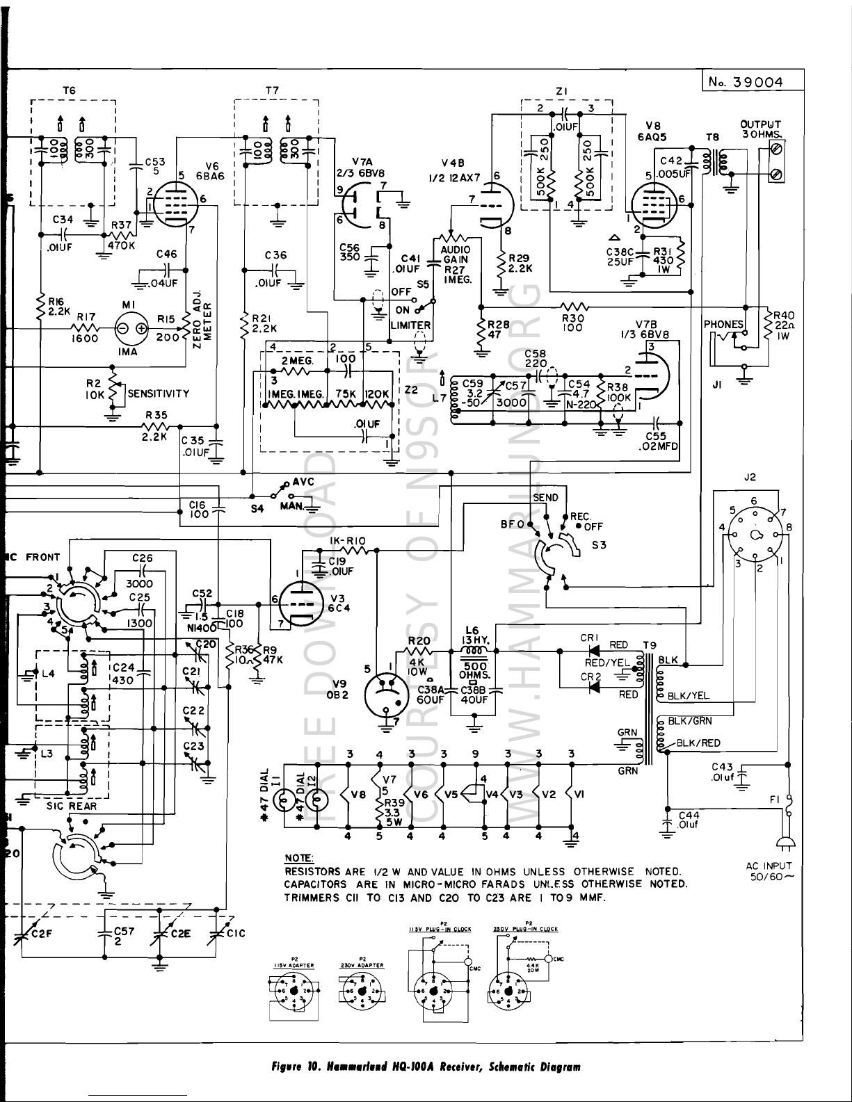
- - - - - -
>R40
>22n
>
IW
p~~
JI *
VS
OUTPl:JT
6AC5
T8
30H~
5.~~2J:::::~IIr-
~
I
(S.~_::
6
.J,.
'-=-
~~-
2
A
_--,
C3SC-:::
R31
25UF-'-
430
IW
A
I
.OIUF
:
I,......."..
~
I 0 0 I
I::~I/')
~;;:::::
I
INN
I:l'
:l'
I
I
0<
< 0 I
I
~
> <
~
I
1'--
I
4~
I
L
....J
~
S
112
12AX7 _ 6
7 _
.....
l;;s
vvv
C56 r
AUDIO
350
I
.0T~~
::~~~
S5
IMEG.
,',
OFF
6
9 7
~
C36
~th-
-
:i
ON~~
R
21
- LIMITER
<
2.2K
(\
r+-4-----~--
5-_...,...L
I 2MEG.
Iqp
,=
.--'1'+-.3.JV\.
vvf\vr-
......
-",
I~
.-+----.
I
I r
I IMEG.IMEG.
7..
5
A
K
12P~
I
Z2
I
TVV
v
vv:
: I
'~IUF:
I
L
C35
I
-::::-
.OIUF
T7
:-------
--,
: a
~
i
,--
__
---l--.-------..
:~~~:
I I
I I
I I
L- -
-r
--~
2.2K
R2
S
10K
tJSENSITIVITY
-=-
R
35
- A A A
-;
>RI6
MI
00::
>2.2K
RI7
RI5 <
«w
01-
1600
+
o::W
200<
w::iE
IMA
N
T6
r-------.,
, I
:
~
a :
:::~g~~g:::
,
~
~;I
::;;;:C53 V6
• ~ __
--l
j
~15
~~
6:A6
C34
- R37
II
- A = 7
.OIUF
470K
-=~
C46
-f=.oJt;
J2
SEND
~7
fREe
~:
6:~
BFO r
~e____.-0:-F3----__+......,
4
~~,'
IK-
filS,>
AVC
M~
S4
.C
FRONT
I
C~6
J- CI9
I •
"""'TIlr-
I
~.OIUF
2
l-t;)
3000
~-
.....
--~.((~
.... --\\
C25
Cr,2
6f::--
V3
__
~.\\\'I.
u.·._
....
fL
~l
CIS
---
6C4
r--
~~
......
13--1~_0
.
·H-+-:-NI7<~;'
....
06...,SOO
7
...-------------.
?b~::~
V7A
V4B
213
6BVS
GRN
GRN
~
0(
,....
RED
3
J
V2 <VI
33 9 3
3
•
7
c
C3SAfc;r
60UF
40UF
3 4
V9
OB2
....J
~d
~'
/
~
= «
~
\"V7
~
(10
0.",
VB
5
V6
.,.
\!
.,.
))
>R39
.,.
>3.3
5W
"9
20
r--
...
----~
.
let
1\,
~
L4
~
II
IC24
C21
=1
~
1430
~'
I a I
'"
~II
I
C22
L
__
~",,\_J
"u
r--
"
I
dt
:
""-
~
"II
~23
=,L3
.......:"
I
~
I
r,j--+----.-t-+-+~~
I
ct
I
l~_~
I c
II
I
--'-- _
__.J
-==
SIC
REAR
"
r----+-I~
.l"~>--~
....
\ •
..;r---++--,
~o
~
---7---
--------7
~R36>R9
>IOJ\,~47K
'
5
~
I I
J
-=-
R
20
I
4K
v
lOW..
454
4
N01E:
L6
.!l!:!,:!.
~.
OHMS.
No.
39004
ZI
r-2-~/-
-3--
1
BlK/YEl
BLK/GRN
.....
BLK/RED
C43
±
,Oluf~
FI
j
C44
RESISTORS
ARE
1/2 W
AND
VALUE
IN
OHMS
UNLESS OTHERWISE
NOTED.
50/60~
CAPACITORS
ARE
IN
MICRO-MICRO FARADS UNLESS OTHERWISE NOTED.
TRIMMERS
CII
TO
CI3
AND
C20
TO
C23
ARE I
TO
9 MMF.
~
~
~.Oluf
5 4 4
AC
INPUT
_I~L_
-
-,-.~/
--7
,VC2F
..,~~57
}~C2E
}~IC
fig."
10.
H
••••rl••
"
HQ·,OOA
R,c,iver,
Scltematic
Diagram
FREE DOWNLOAD
COURTESY OF N9SOR
WWW.HAMMARLUND.ORG

__
!if.
-
-I~
1 T·5
T
r---
.
=
.bJ.I~~F
~!:;M~n~~~~
rC
-a--a-
-1
:
I
~
IlL
I I
~U:
"Q" I
C28
= I
i*6
~
..
=:I
I ',;r.. I V4A -
r<'l
I
V5
::=~
6~f6
,5
MULT.JP
I
3300
C2\~
I I 1/212AX7l I
I
6B:6,.:-_~,
6
I
/::~
S2
R~
~
.'1
~
I
rl
I
L
__
7H(r'~::-==~~'6
"
:6
.8
. 4
~.>510
12R'2
1
5
---
.JI
I
-.-
r
m~.:JJ
\'GL. ---
~JMEG.~
2
---
I
L
-
-.1-
-
~
I
C3'
I
zp
, .> -
7r
3 =
=
7
Hr
r----,
~
RI3
.OIUf
C31
R6·~O,~:=hc'0:=
•
10K
~
C30
180
.~
.O'UFI
SELECTIVITY
-.ej~
-=.E:-
"='~
=
.01
UF
~·~~t(F
::!:-
RI4
• R8 >R16
:
6.2K
•
2.2K
>2.2K
C45
fl~UFRI9
•
-
180>
"'---l--+--
C33-±-
•
04UF
:f:.
C5 _
C32..,!,o
.0IUF.,J
.0IUF~
R5
•• 22K
•
R3
10K
-::~
C8
SIC
FRONT
SIA FRONT SIB
FRONT
.01
UF
T
L-
...-----
....1
...-------eJ--l1..l
--------,
C
17
"'ML~I
~~~,~>--I--I
C50
2
...---_.:2
...
v""""","' -----,
R4
~
..d~~"""'"
'\
\.
_
.....
..
n._".........
__
--,
IK > = 100
~ll
..
3
5:_.f1\\
U
2.~
+
......4 \.,
./'" •
"""--4
\.'- A
.....
-+----,
N220
c
~~1;;--7""':"":-:"":-=l---+-+-+-""
~t~
~~'c;~~j~=1_~_~-+----,
~~
__
=~?-'"i'~'-f-=-""~---+--+-""
IT~
~
L2
~~
:
~=LJ_~
-~
~I:
L
__
~!-J
;;-='-=f.=o=l---+-..
L--+-~4~
~=-=_~=
~
=~
~.E:"
I\~
~
LI
lj
t :
iTt
~ ~ 3 ~
CI5
I
~
I ~
+-
_
~'
~II
I
....
.......
'-----i
.....
-i--.....-=-+-+-+-H--.. I
SIA REAR
~C6
OI~F
L._
-
.~
,IOIUF
.
.-------+-t-+-'
r-')~
...
~32
0:
~
~
SIBREARnq~·
~-+-+-'
..L--
=
.--
C7
.:r::..OIUF
,,----=7------------
....
----
- -
-----r---7--------------7-
·-€fL3
I
I
J
~;B._.
;~~A
~~~-
-~~3---
---
--~~~4~ -?V;:D-~~;C
--
)V~;--
--
--~k?:F-'
9.5TOzv IO.lTOlEl5;-
IIT0360 / 3.2T052
68NPO'
'" /
-==-
ANTENNA
FREE DOWNLOAD
COURTESY OF N9SOR
WWW.HAMMARLUND.ORG

THE
HAMMARLUND
MANUFACTURING
COMPANY
Standard
Warranty
The Hammarlund Manufacturing Company, warrants this equipment to
be
free from defects
in workmanship
and
materials under normal
and
proper use
and
service for
the
uses
and
purposes for which it
is
designed,
and
agrees
to repair
or
replace, without charge, all parts
thereof showing such defects which
are
returned for Inspection to
the
Company's factory,
transportation prepaid, within a period of
90
days
from
date
of
delivery, provided such Inspec-
tion discloses to the satisfaction of
the
Company
that
the defects
are
as
claimed,
and
provided
also,
that
the equipment
has
not been altered, repaired, subjected to misuse, negligence or
accident,
or
damaged
by lightning, excessive current
or
otherwise, or
had
its serial number
or
any
part
thereof altered, defaced,
or
removed. Tubes shall
be
deemed to
be
covered
by
the
manufacturer's
standard
warranty
applicable thereto,
and
such Items shall
be
and
are
hereby
excluded from the provisions of this warranty. Pilot lamps
and
fuses
are
not
guaranteed
for
length of service.
Except
as
herein specifically provided, no warranty, express or implied, other
than
that
of
title, shall
apply
to
any
equipment sold hereunder.
In
no event shall the Company
be
liable
for
damages
by
reason of
the
failure
of
the equipment to function properly
or
for
any
consequential
damages.
This
Warranty
Is
valid for
the
original owner of the equipment,
and
Is
contingent upon receipt
of the Warranty Registration Card by
the
Company. No equipment shall
be
returned to the
factory for repairs under
warranty
unless
wri"en
authorization
is
obtained by the Company,
and
the
equipment
is
shipped
prepaid
by
the
owner. The Company maintains Authorized
Service Stations, names
and
locations of which will
be
sent upon request of the owner.
The Hammarlund Manufacturing Company
A
Giannini
Sci.ntific
Co.
73·88
Hammarlund
Drive,
Mars
Hill,
N.
C.
Expo"
Departmant:
13
East 40th St,eet, New Yo,k 16, N.
Y.
Th.
policy
of
tha Hammarlu.... Manufacturing Campony, is
ona
of
continuad
improvemant in dooign
and
manufacture
wharever
and
whanaver possibla,
to
provida tha
higha.t
attainobla
quality a .... porformanca. Hanca, .pacifica-
tion., finishOl, ate.
are
subject
to
maltJa
without notice a .... without
a.sump-
tion
by
Hammarlund
of
any obligatIon
or
responsibility to provide
sum
features CIS may
...
manged,
odded
or
dropped
from previous production
runo
of
thi.
aqulpment.
Hammarlund
Manufacturing
Company
A Giannini Scientific Co.
73-88
Hammarlund
Drive.
Mars
Hill.
N.
C.
Export
Department:
13 East
40th
Str.et,
New
York
16,
N.
Y.
DO
NOT
MAKE
ANY
RETURNS
WITHOUT AUTHORIZATION FROM
THE
FACTORY.
ALL
AUTHORIZED
RETURNS
SHOULD
BE
SHIPPED
TO
HAMMAR-
LUND
MANUFACTURING CO.,
ATTN.
CUSTOMER
SERVICE,
MARS
HILL,
NORTH
CAROLINA.
FREE DOWNLOAD
COURTESY OF N9SOR
WWW.HAMMARLUND.ORG

---
-----~-----.-..~~~~----~~------~----
ESTABLISHED
r9ro
FREE DOWNLOAD
COURTESY OF N9SOR
WWW.HAMMARLUND.ORG
 Loading...