


Ref. 2035481/03.08-en
15202-10
/i
HD 8 VV
HD 10C VV
Applying from factory No. H1700001
Operating instructions
with safety notes

© HAMM AG 2009
The disclosure as well as the duplication of this document, the use and the forwarding of its contents, are forbidden as far as not expressively permitted. Violations will cause indemnities. All rights with respect
to patent, utility sample or design patent registration reserved.
HAMM AG
D-95633 Tirschenreuth/Germany
P .O. Box 1160
Telephone +49-96 31/80-0
Fax +49 96 31/80 120
www.hamm.eu

© HAMM AG 2009 I
/i
Operating instructions
with safety notes
Tandem Roller
HD 8 VV
HD 10C VV
HAMM AG • D-95633 Tirschenreuth/Germany • P. O. Box 1160 • Telephone +49 96 31/80-0 • Fax +49 96 31/80 120

II © HAMM AG 2009
TABLE OF CONTENTS
Table of contents
1 GENERAL 1
1.1 Introduction 1
1.1.1 General 1
1.1.2 Foreword to the operating instructions 2
1.1.3 Special identifications in the text 3
1.2 Use 4
1.2.1 Intended use 4
1.3 Notes 5
1.3.1 Indications on sound and vibration 5
1.3.2 Installation instructions for safe ty device ROPS
anti-rollover bar 6
1.3.3 Safety 7
1.3.4 Fuel 15
1.4 Identification of the roller 16
1.4.1 Type sign, VIN. 16
1.5 Technical data 16
1.5.1 Loading and transport 16
1.5.2 Dimension sheet HD 8 VV 18
1.5.3 Dimension sheet HD 10C VV 19
1.5.4 Technical data HD 8 VV 20
1.5.5 Technical data HD 10C VV 22
2 OPERATION 24
2.1 Control and operation elements 24
2.1.1 General 24
2.1.2 Overview 24
2.1.3 Description of elements 28
2.2 Driving 41
2.2.1 General 41
2.2.2 Precaution measures prior to machine start 43
2.2.3 Start of engine 44
2.2.4 Driving 46
2.2.5 Driving with vibration 46
2.2.6 Stop, switch off engine, leave machine 48
2.2.7 Operation monitoring 49
2.2.8 Towing 50
2.2.9 Water irrigation 52

© HAMM AG 2009 III
TABLE OF CONTENTS
3 MAINTENANCE 54
3.1 Introduction 54
3.1.1 General 54
3.1.2 Notes on spare parts ordering 55
3.1.3 Safety 56
3.1.4 Use of biologic hydraulic oil 57
3.1.5 Refrigerant conditioning 57
3.2 Lubrication indications 58
3.2.1 Viscosity - temperature range 58
3.2.2 Lubricants used in delivery status 59
3.3 Maintenance overview 60
3.3.1 Maintenance plan 60
3.3.2 Required maintenance parts HD 8 VV, HD 10C VV (3W35) 61
3.3.3 Maintenance parts (Service kits) HD 8 VV,
HD 10C VV (3W35) 61
3.3.4 Required maintenance parts HD 8 VV, HD 10C VV (3W35) 62
3.3.5 Maintenance parts (Service kits) HD 8 VV,
HD 10C VV (3W35) 62
3.4 Running-in regulations 63
3.4.1 After 50 operating hours 63
3.5 Operation monitoring 64
3.5.1 Operation monitoring 64
3.5.2 Dry air filter 64
3.6 Maintenance once every 10 operating hours 65
3.6.1 Maintenance points at the engine for engine oil change 65
3.6.2 Check and clean dry air filter 65
3.6.3 Control of oil level in the hydraulic oil tank 66
3.6.4 Control of refrigerant level for engine cooling system 66
3.6.5 Control of parking brake and EMERGENCY STOP
function (NOT-STOP) 67
3.6.6 Clean the water filter for the pressure irrigation system 67
3.6.7 Cleaning the spay nozzles 68
3.7 Maintenance once every 250 operating hours 69
3.7.1 Lubricate articulated frame steering joint 69
3.7.2 Lubrication of steering cylinder rod 69
3.7.3 Control of radiator 70
3.7.4 Control of the scrapers 70
3.8 Maintenance once every 500 operating hours 71
3.8.1 Replacing the filter insert for the hydraulic system 71
3.8.2 Replacing the preliminary fuel filter 71
3.9 Maintenance once every 2000 operating hours,
at least once a year 73
3.9.1 Replacement of hydraulic oil 73
3.9.2 Changing the refrigerant 74
3.9.3 Cleaning the water irrigation system 76
3.9.4 Visual inspection of hydraulic system 76
4TABLES 77
4.1 Diagnostic Code 77

IV © HAMM AG 2009
TABLE OF CONTENTS

© HAMM AG 2009 1
GENERAL
1 GENERAL
1.1 INTRODUCTION
1.1.1 General
You have purchased a HAMM Quality product.
All parts of this machine have been tested and
verified carefully. They correspond to the quality you expect.
This machine has been built according to the
current state-of-the-art and the current safety
regulations. However it is indispensable to
read and to observe the safety notes a s well as
the operating and the maintenance instructions
prior to start-up. Every inappropriate use, or
use not according to the intended use, of the
machine will cause:
• Dangers to life and health of the user or to
third parties
• Impairment of the machine and further
properties of the user
• Dangers to the efficient work of the machine
The operating instructions of the combustion
engine is a part of the overall operating inst ructions. Maintenance and care of the engine
have to be performed according to these operating instructions. Any safety notes have to be
followed.
Even if the regulations for safety, use and
maintenance are followed, residual dangers
will remain. Due to the high operating weight
and to the high distance of gravity centres of
the machine, there is considerable danger of
tilting, in particular during travels in transversal
direction to slopes. The smooth surface of the
drums or the tyres, respectively, decreases lateral stability of wet, uneven ground. Operation
is not admitted on snow and ice. When driving
on hard surfaces, and in particular when driving in transversal direction so slopes, lateral
stability is decreased when the vibration is
switched on (danger of falling).
The high reliability of the machine is preserved
through correct use and careful maintenance.
This includes the use of the obligatory operating resources and the use of original HAMM
spare parts.
This manual will introduce you to the operation
of the machine. You will find the following in it:
• Regulations for your safety
• The introduction of the machine and its
characteristics
• The operation
• The maintenance instruct ions
• Indication on spare parts management
and customer service
Our representations will help you to keep your
roller in perfect operating condition.
Our representations will be at your disposition
with consulting and service even after the warranty period. They will provide our original
HAMM spare parts which do not only correspond to the technical requirements but also
ensure exchangeability and quality.
Our customer service training centre holds
courses for roller drivers.
It will give drivers:
• General safety information
• Information on use and maintenance of
the machine
• Information on the practical use of the roller
• Information of a more rational use with
add-on devices
Furthermore, our specialist sales advisors are
always at your disposition. They will offer you
the optimum product solution for your application. The safety, operation and maintenance
notes included in this manual are intended to
be used by roller drivers and mechanics.
Thus, keep this manual always at hand!

GENERAL
2 © HAMM AG 2009
1.1.2 Foreword to the operating
instructions
These operating instructions shall facilitate the
introduction to the machine and the use of thei r
intended operational possibilities.
The operating instructions includes valuable in formation in order to operate the machine safe ly, appropriately and economically. The observation of the operating instructions will help to
avoid dangers, decrease repair cost and do wntimes, and to increase reliability and lifetime of
the machine.
These operating instructions must be updated
with instructions due to existing national accident prevention and environment protection
regulations.
The operating instructions must always be
present at the place of utilisation of the machine.
The operating instructions of the combustion
engine are a part of the overall operating instructions of the machine. Maintenance and
care of the engine have to be performed according to these operating instructions. Any
safety notes have to be followed.
These operating instructions must be read and
applied by all persons ordered with works with
or on the machine, e.g.
• Operation including care, disposal of operating supply or auxiliary substances
• Servicing (maintenance, inspection, repair) and/or
• Transport.
Apart from these operating instructions and the
binding accident prevention regulations applying in the country of use and at the place of utilisation, also the generally accepted specialist
rules for appropriate and safe work have to be
observed.

© HAMM AG 2009 3
GENERAL
1.1.3 Special identifications in the text
The following symbols or notes are used for
the identification of text which do not apply to
all machine variants:
/i
/i
/i
Positions in figures
The positions in the figures are represented
with letters and numbers. The positions identified with letters in alphabetical order are only
explained in the corresponding text segment,
beginning new for each single figure. The positions identified with numbers correspond to the
numbering of the plates for operating elements, control devices and switches. They are
identical to the numbers of the individual operating and control elements. In the describing
text, these position numbers are in brackets.
Among other things, this ensures that important and additional information can be found
immediately and without difficulties in the descriptions of the elements.
All rights reserved
No part of this publication my be reproduced,
processed, copied and/or published in any way
(imprint, photocopy, microfiche or any other
procedures) without the written consent of
HAMM. This also applies to the corresponding
drawings and schemes.
HAMM reserves the right to change individual
parts at any time without previously informing
the customer. The contents of this publication
can also be changed without prior announcement.
This publication applies to the standard design
of the previously listed machine types. Therefore it is possible that these instruct ions include
descriptions of components not installed in
your machine. HAMM does not accept liability
for possible damages resulting from the application of this publication on machines deviating from the standard design.
Please contact to the customer service of your
supplier for all information about adjustment,
maintenance or repair work not included in this
publication.
Only for machines with CE equipment
Only for machines without CE equipment
Option Special equipm en t

GENERAL
4 © HAMM AG 2009
1.2 USE
1.2.1 Intended use
The machine may only be deployed on surfaces that can support it. It is intended solely for
deployment for compressing loose surfaces,
road foundations, road surfaces and similar
compactible foundations. Any other deployment or a deployment beyond this is not
deemed as intended. The manufacturer/supplier is not liable for any damage resulting from
this. The user will bear the complete risk.
The intended use also includes the observance of the operating instructions as well as
the compliance with the inspection and maintenance requirements set out by the manufacturer.
This machine has been built according to the
state-of-the-art and the generally accepted
safety regulations. However, danger for life
and health of the user or impairment of the machine and of other objects can arise during the
use of the machine.
This machine ma y only be used in technic ally
unobjectionable condition, as well as according
to the intended use, and aware of safet y issues
and possible dangers, always observing the
operating instructions. All safety devices removed for transport purposes (anti-rollover device ROPS, handles, silencers etc.) must be installed to the machine prior to using it. In particular, any troubles which could have effect on
safety must be eliminated immediately.
Arbitrary changes will exclude the manufacturer's liability for any damage resulting from this.

© HAMM AG 2009 5
GENERAL
1.3 NOTES
1.3.1 Indications on sound and
vibration
The subsequently listed sound and vibration
indications correspond to the requirements of
the CE Machinery Directive in the version
2006/42/EG.
The sound emission of the machine was measured according to the CE Sound Emission Directive in the version 2000/14/EG.
Sound indication for driver's seat
The sound pressure level at the place of the
operator, required according to Appendix 1,
section 1.7.4.2 of the CE Machinery Directive,
is:
HD 8 VV....... .. .. ....................... L
pA
= 84 dB(A)
HD 10C VV ............................. L
pA
= 84 dB(A)
Sound emission of the machine
The sound power level of the machine, required according to Appendix 2 of the CE
Sound Emission Directive, is:
HD 8 VV............................... L
WA
= 106 dB(A)
HD 10C VV .......................... L
WA
= 106 dB(A)
Vibration indication
The vibration indications for the whole-body vibration on the driver's seat, requ ir ed accord ing
to Appendix 1, section 3.6.3.1 of the CE Machinery Directive (weighted effective acceleration calculated according to ISO 2631 part 1),
are:
HD 8 VV.... ..........................................0.3 m/s
2
HD 10C VV ..................... ... .................0.3 m/s
2
GENERAL
6 © HAMM AG 2009
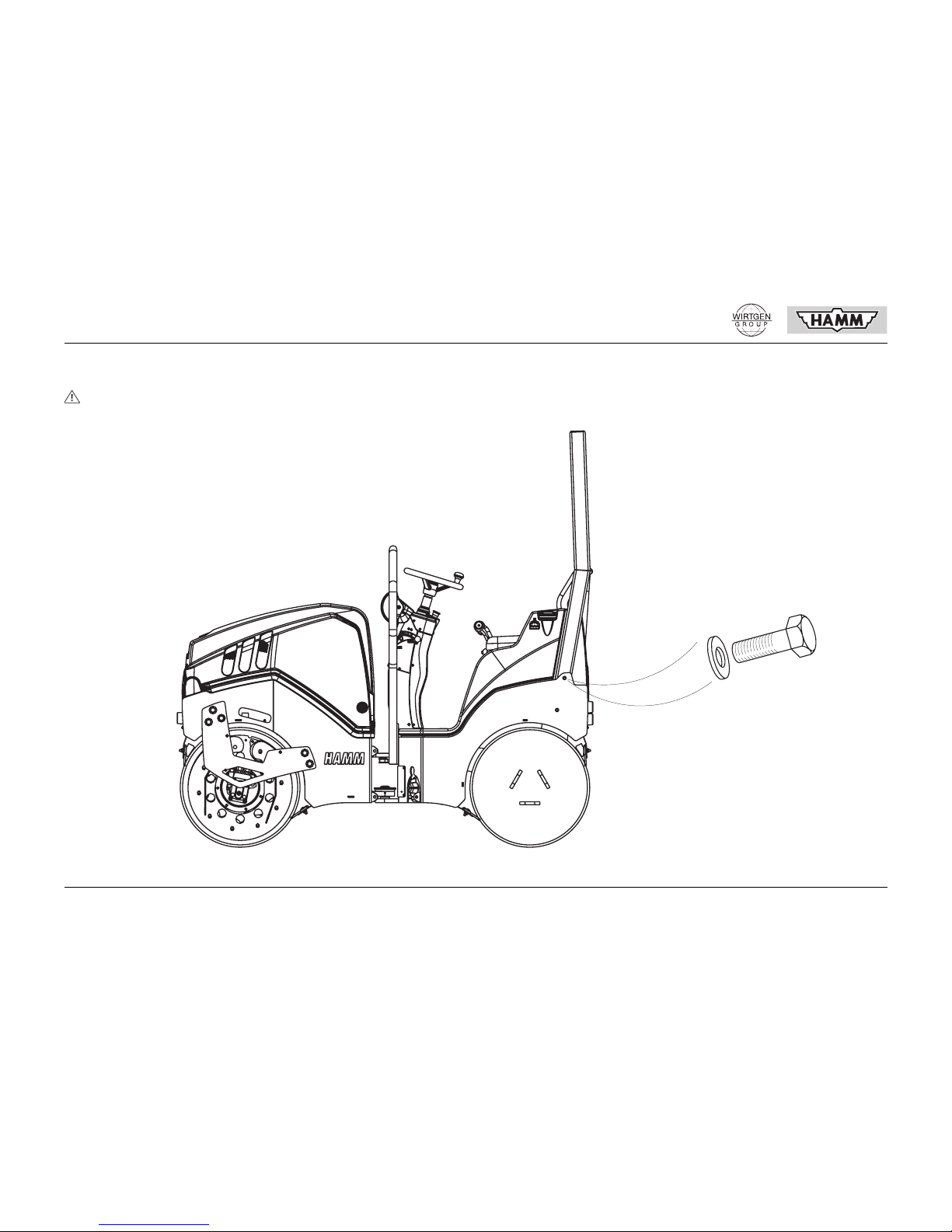
1.3.2 Installation instructions for safety device ROPS anti-rollover bar
The machine may only be operated with installed anti-roll over device!
10081-10
M16x50
Mt 209 Nm

© HAMM AG 2009 7
GENERAL
1.3.3 Safety
The safety notes summary applies to several machine types with different equipment.
Thus, it may be possible that some safety
notes are listed which do not apply to your
machine type.
Warning notes and symbols
The following denominations or symbols are
used in the operation instructions for indications of special importance. Please disclose
these safety instructions also to other users.
Principle; intended use
• This machine has been built according to
the state-of-the-art and the generally accepted safety regulations. However, danger for life and health of the user or impairment of the machine and of other objects
can arise during the use of the machine.
• This machine may only be used in technically unobjectionable condition, as well as
according to the intended use, and aware
of safety issues and possible dangers, always observing the operating instructions.
All safety devices removed for transport
purposes (anti-rollover device ROPS, handles, silencers etc.) must be installed to
the machine prior to using it. In particular,
any troubles which could have effect on
safety must be eliminated immediately.
• Arbitrary changes will exclude the manufacturer's liability for any damage resulting
from this.
• The machine may only be deployed on
surfaces that can support it. It is intended
solely for deployment for compressing
loose surfaces, road foundations, road
surfaces and similar compactable foundations. Any other deployment or a deployment beyond this is not deemed as intended. The manufacturer/supplier is not liable
for any damage resulting from this. The
user will bear the complete risk.
• The intended use also includes the observance of the operating instructions as
well as the compliance with the inspection
and maintenance requirements set out by
the manufacturer.
Immediate danger; possible consequences:
Death or very severe injuries.
Possibly dangerous situation; possible
consequences:
Death or very severe injuries.
Dangerous situation; possible consequences:
Light or insignificant injuries, warning of
property damage.
Possibly detrimental situation; possible
consequences:
The product or things in its surrounding
may be damaged.
Hints on application and useful information.
No information warning against a dangerous or detrimental situation.

GENERAL
8 © HAMM AG 2009
Organisational measures
• The operating instructions must always be
stored readily available at the place of application of the machine (in the tool case or
in the container for this purpose).
• The operating instructions of the combustion engine are a part of the overall operating instructions of the machine.
• The generally applying legal and other
binding accident prevention and environment protection regulations must be observed and instructed supplementary to
the operating instructions.
• Such duties may also concern, e.g., the
handling of hazardous substances or the
disposition/wearing of personal protection
equipment, as well as provisions of traffic
law or occupational health regulations.
• The operating i nst ructi ons mus t be s upple mented by instructions for taking into account factory-related particularities, including supervision and notification duties.
• The personnel ordered to perform activities with this machine must have read
these operating instructions, and in particular the safety section. It is too late to do
this during work. This is particularly true
for staff only working occasionally on the
machine, e.g. for repair and maintenance.
• The safety and danger awareness of the
personnel during work, taking into account
the operating instructions, must be controlled at least from time to time.
• The personnel must not wear open long
hair, loose-fitting clothes, or jewelry, including rings. Danger of injury due to
catching or pulling-in.
• Personal protection equipment must be
used as far as necessary or as required by
regulations.
• All safety and danger indications at the
machine must be observed.
• All safety and danger indications on/at the
machine must be kept complete and legible.
• Any changes, conversions, add-ons to the
machine, which could impair safety, must
not be performed without the approval of
the manufacturer. This also applies to the
installation and the adjustment of safety
devices and valves as well as for welding
on load-bearing parts.
• S pare parts must comply with the technical
requirements determined by the manufacturer. This is always ensured for original
spare parts.
• Hydraulic hoses must be replaced in the
defined or appropriate intervals, even if
safety-relevant defects cannot be detected.
• Any intervals for recurring inspections/
tests defined or indicated in the operating
instructions must be kept.
• A workshop equipment corresponding to
the work is absolutely necessary for performing servicing work.
• The installation of tires requires sufficient
knowledge and appropriate mounting
tools.
• The storage places and the use of fire extinguishers must be announced.
• Fire alarm and fire extinguishing possibilities must be observed.

© HAMM AG 2009 9
GENERAL
Selection and qualification of staff; general
duties
• Any work with or on the mach ine must only
be performed by appropriate and reliable
staff. The minimum legal age must be observed.
• Only trained or instructed staff may be
used.
• The responsibili ty of the st af f for operat ion ,
maintenance and servicing must be clearly
defined.
• It must be ensured that the machine is only operated by staff ordered to do this.
• The responsibility of the machine operator
- also with respect to traffic regulations must be defined; these must allow him or
her to reject unsafe instructions of third
parties.
• Any staff to be trained, instructed, taughtin, or any staff within a general education
measure, may only work on the machine
under the continuous supervision of an experienced person.
• Any work on electrical equipment of the
machine may only be performed by a specialised electrician or by instructed persons under the supervision of a specialised electrician and according to the rules
of electric engineering.
• Any work on suspensions, braking and
steering installations may only be performed by specialised staff trained for this.
• Only staff with specialist knowledge and
experience of hydraulics may work on hydraulic installations.
Safety notes on certain operation phases
Normal operation
• All working modes which are questionable
with respect to safety must not be performed.
• The operator mus t get familiar to the working environment at the place of utilisation
prior to the start of wor k. The work ing envi ronment includes e.g. the obstacles in the
working and traffic area, the load carrying
capacity of the underground and necessary safeguarding of the working site towards public traffic.
• Measures must be taken which only allow
the operation of the machine in a safe and
functional condition. Only operate the machine if all protection devices and safetyrelated devices, e.g. detachable protection
equipment, EMERGENCY STOP devices
(NOT-STOP), sound protection devices,
aspiration devices, are existing and operative.
• The machine must be inspected with respect to visually detectable damages and
defects at least once per shift. Any occurred changes (including changes of the
operational behaviour) must be notified
immediately to the responsible entity/person. If necessary, immediately shut down
and secure the machine.
• In case of malfunctions, the machine must
immediately be shut down and secured.
Have the malfunction eliminated immediately.
• Starting the engine and conducting the
machine may only be performed from the
drivers seat. Do not start the engine by
short-circuiting the electric connections at
the starter, since the machine could immediately start moving. Also, the function of
the starter protection switch must not be
overridden.
• Get familiar with all devices and operating
elements as well as with the functions of
these prior to starting the engine. It is too
late to do this during work.
• The acceleration and braking behaviour of
the machine are influenced by viscous hydraulic oil. For this reason, warm up the
machine during the warming phase with
moderate speed and low load until the hydraulic oil has heated to 20 °C (68 °F).
• Always wear a safety belt during travel.
• Never adjust the driver's seat during travel.
• The vibration function must never be used
in the immediate vicinity of buildings (danger of collapse). Prior to switching on the
vibration function, ensure that any lines
laid in the underground (gas, water, sewage, electricity lines) are not damaged or
destroyed.
• Observe all switching processes and control displays according to the operating instructions.
• Prior to starting the machine ensure that
nobody can be put into danger by the
starting of the machine.

GENERAL
10 © HAMM AG 2009
• Prior to driveaway, check for persons in
the immediate vicinity of the machine.
• Prior to driveaway/start of work, check
whether the brakes, the EMERGENCY
STOP device (NOT-STOP), the steering
system, and the signaling and illumination
installations are operative.
• Check for sufficient vision. Adjust necessary mirrors correctly.
• Prior to driveaway, always check the accident-safe storage of accessories. Lift attached add-on devices off the ground.
• Never leave the driver's stand during travel.
• In emergency situations and when
there is a danger, bring the machine to an
immediate stop by operating the EMERGENCY STOP switch (NOT-STOP).
• Do not use the EMERGENCY STOP
switch (NOT-ST OP) as service brake.
• In emergency situations and when
there is a danger, bring the machine to an
immediate stop by operating the parking
brake!
• Do not use the parking brake as the
service brake.
• When driving on public roads and places,
observe the applying traffic regulations
and bring the machine to an admissible
condition with respect to traffic law, if necessary.
• In case of bad visibility and in darkness always switch on the lights.
• It is forbidden to transpor t passengers.
• Always check for sufficient clearance
when passing underpasses, bridges, tunnels, overhead lines etc.
• Always keep sufficient distance to borders
of excavation pits and batters.
• Do not use any working procedure that
would impair the stability of the machine.
• The driving speed must always correspond to the conditions of the surroundings.
• Do not drive slopes in transversal direction; keep working equipment and loaded
goods always near to the ground, in particular when driving down slopes.
• Avoid driving sudden curves when driving
up or down slopes.
• Always switch to a lower gear before a
slope, never on the slope.
• Before leaving the driver's stand, always
prevent the machine making unintentional
movements (0 position lock engaged,
parking brake applied, engine switched
off).
• If the driver removes from the machine, he
or she must pull out the ignition key and
lock the cabin door and, if applicable, the
cabin doors or the dashboard cover.
• Lower down completely any installed additional devices prior to leaving th e machi ne.
• Never jump from the machine (risk of injury). Use the climbing steps and the grips.
• Disconnect the engine from electrical supply with the battery disconnector.
Special work in the scope of machine
utilisation, servicing work, as well as
troubleshooting during working
procedures; disposal
• Comply with adjustment, maintenanc e and
inspection work and schedules defined in
the operating instructions as well as with
indications on the replacement of parts/
partial equipment. Only specialised staff is
authorised to perform such works.
• Inform operating staff prior to the start of
special work and servicing work. Keep unauthorised persons off the machine during
these works. Denominate a supervisor.
• During all works concerning the operation,
the production adaptation, the conversion
or the adjustment of the machine and its
safety-related devices, as well as inspection, maintenance and repair, observe
processes for switching on and off according to the operating instructions as well as
the notes for servicing work.
• As far as necessary, safeguard the servicing area spaciously.
• Protect the machine against unexpected
starting during maintenance and repair
work.
For this:
• Lock the main command devices and
pull off the key
• Pull off the key from the battery dis-
connector and
• Attach a warning sign to the steering
wheel.

© HAMM AG 2009 11
GENERAL
• Generally, all maintenance and servicing
work may only be performed when the engine is at a standstill.
• Only open the engine hood when the engine is at a standstill.
• Keep away from moving, rotating or revolving parts; do not touch these (danger
of accidents).
• Only perform maintenance and servicing
work if the machine is parked on a level,
stable ground and if it is secured against
rolling away and buckling (danger of bruising).
• Perform maintenance and servicing work
below the lifted driver's stand only when
the lock is latched in. Engine bonnet always fully open (danger of life).
• After maintenance and servicing activities
that require the lifting of the driver's stand,
the driver's stand must be reattached/
screwed to the engine frames. This is the
only way to ensure the roll-ov er protection.
• Individual parts and bigger assemblies
must be attached carefully to lifting equipment and safeguarded in a way that no
danger can emanate from these. Only use
appropriate and technically unobjectionable lifting equipment as well as load-carrying equipment with sufficient loading capacity. Do not rest or work under suspended loads.
• Only order experienced persons with the
fixing of loads and the guidance of crane
operators. The guiding person must be in
visible range of the operator or have a
speaking contact to him or her.
• During installation work above body
height, use safe climbing aids and working
platforms intended for this purpose. Do not
use machine parts as climbing aids. In
case of maintenance work in greater
heights, wear fall protection. Keep all handles, steps, handrails, pedestals, platforms, ladders, free from dirt, snow and
ice.
• Clean all oil, fuel, and care agent residues
from the machine, in particular from connections and screwed connections, prior
to maintenance and repair work (fire hazard). Do not use aggressive cleaning
agents. Use fibre-free cleaning cloth.
• Prior to cleaning the machine with water,
vapour stream (pressure washer) or other
means of cleaning, cover/seal all apertures which must not be penetrated by water/steam/cleaning agent due to safety or
functionality reasons. Electric motors and
distribution cabinets are specially endangered in this respect.
• After cleaning, the covers/seals must be
taken off completely.
• After cleaning, check all fuel lines, engine
oil lines, and hydraulic liquid lines for
leaks, loose connections, chafe marks,
and damage. Eliminate detected defects
immediately.
• Always tighten any screwed connections
loosened during maintenance and servicing work.
• If the removal of safety devices is necessary for rigging, maintenance and repair,
the safety devices have to be re-installed
and checked immediately after the end of
the maintenance and repair work.
• Take care for a safe and environmentfriendly disposal of operating and auxiliary
substances, replaced parts and contaminated cleaning material.

GENERAL
12 © HAMM AG 2009
Notes with respect to special types of
danger
Electrical energy
• Only use original fuses with the correct
power value. Immediately shut down the
machine in case of troubles in the electric
power supply.
• During the start of the machine with battery connection cables, always connect
the positive pole to the positive pole and
the negative pole to the negative pole. Always connect the negative pole last and
disconnect it first.
• Keep sufficient distance between the machine and overhead voltage lines. During
works near electric overhead lines, the
equipment must not come near to the
overhead lines. Danger of life! Inform your self about safety distances to be kept.
• After touching high-voltage lines:
• Do not leave the machine
• Drive the machine out of the danger
area
• Warn surrounding persons not to
come nearer and not to touch the machine
• Have the voltage shut down
• Only leave the machine after it abso-
lutely sure that the touched/damaged
line is de-energised.
• Any work on electrical installations or operating resources may only be performed
by a specialised electrician or by instruct-
ed persons under the supervision of a specialised electrician and according to the
rules of electric engineering.
• During works at the electric installation,
the machine must be de-energised at the
battery disconnector or by disconnecting
the negative pole (earthing strip) at the
battery.
• Do not smoke during maintenance work at
the battery (danger of explosion). Keep
away igniting sparks or open flames.
• Dispose used batteries properly.
• The electrical equipment of a machine
must be inspected/tested regularly. Any
defects, as e.g. loose connections or burnt
cables, must be eliminated immediately.
• Only use tools insulated against voltage.
Gas, dust, vapour, smoke
• Only operate combustion engines and fuel-operated heating systems in sufficiently
ventilated areas. Take care for sufficient
ventilation before starting in closed rooms
(danger of poisoning). Observe t he regulations applying for the respective place of
application.
• The operation of the machine is inadmissible in places where flammable gases or
dusts can occur (e.g. near fuel storage areas, coal storage areas, cereals storage
areas, wood dust or similar).
• Unusual sounds and strong smoke exhaust of the engine during operation can
point to dangers. Find out the cause and
have the damage repaired.
• Welding, torching and grinding work may
only be performed at the machine if this is
expressivley admitted. There may be fire
and explosion hazard.
• Prior to welding, torching and grinding,
clean the machine and its surroundings
from dust and flammable substances and
take care for sufficient ventilation (danger
of explosion).
Hydraulic system, pneumatic system
• Only staff with specialist knowledge and
experience of hydraulics may work on hydraulic installations.
• All lines, hoses and screwed connections
must be checked for leaks and visible
damage (at least once per year). Damaged parts must be replaced immediately.
Further operation is inadmissible. Oil
spurting out can lead to injuries and fire.
• Liquids spurting out under high pressure
(hydraulic oil, fuel) can penetrate the skin.
In case of such injuries consult a doctor
immediately; otherwise, severe infections
may occur.
• Prior to work on hydraulic lines, safeguard
the machine against rolling away (parking
brake, wedges). Lower down add-on devices completely. Only then remove the
pressure from the lines.
• Remove the pressure from system sections to be opened and from pressure lines
(hydraulics, compressed air) according to
the assembly descriptions prior to beginning the repair work.

© HAMM AG 2009 13
GENERAL
• Lay and install hydraulic and compressed
air lines appropriately. Do not confuse connections. The fittings, the length and the
quality of the hose lines must comply with
the requirements.
Noise
• Sound protection devices at the machine
must be in protection position during operation.
Fuel, oils, greases and other chemical
substances
• Only appropriate and clean lubricants may
be used. Otherwise the guarantee becomes void.
• During the handling of oils, greases and
other chemical substances, observe the
safety regulations applying for the respective product.
• Do not heat oil above 160°C (320 °F); otherwise, oil or oil vapours may ignite.
• Prior to fil ling up fuel, switch of f engine and
heating and pull out the ignition key. Do
not fill up fuel in closed rooms. Wipe away
spilled fuel immediately.
• Be extremely careful when handling fuel increased fire hazard. Never fill up fuel
near open flames or igniting sparks. Do
not smoke during filling up!
• Be careful during the handling of brake fluid and battery acid (noxious and caustic).
• Be careful during the handling of hot operation and auxiliary materials (danger of
burning or scalding).
• Release emulsions for tires may only be
mixed from water and release concentrate
according to the indications of the release
agent manufacturer. The environment protection regulations must be observed.
Transport and towing
• Only tow, load and transport according to
the operating instructions.
• Only use appropriate transport means and
lifting hoist with sufficient load capacity.
Take into account the weight and the dimensions (technical data).
• Only use stable loading ramps with sufficient carrying capacity for loading. Take
care not to endanger persons by tilting or
sliding.
• Prior to loading ensure that the vehicle
(e.g. trailer, flat bed etc.) cannot tilt upwards when driving onto the loading area.
• Do not step or rest under suspended loads
(danger of life).
• Do not rest in the danger zone of the machine during the guidance and loading of
the machine (danger of life).
• Use the specified gantries.
• Drive the machine slowly onto or from the
loading area, respectively.
• Safeguard the machine with square timer,
wedges and tensioning ropes against
shifting. Safeguard the attenuation elements of the drum suspension against
overload by means of a support.
• Remove square timbers, wedges and tensioning ropes completely before unloading.
• All safety devices removed for transport
purposes (anti-rollover device ROPS, handles, silencers etc.) must be installed to
the machine prior to using it.

GENERAL
14 © HAMM AG 2009
• During towing, keep the specified transport position, the admissible speed and
the travel path.
ROPS cabin
• The machine frame must not be warped,
bent or cracked in the cabin fixing area
(deformation).
• The reinforcement elements of the ROPS
cabin must not show rust, damage, fissures or open fractures.
• All screwed connections of the reinforcement elements must comply with the given
specifications and must be screwed tightly
to each other (observe tightening torque
values).
• Bolts and nuts must not be damaged, bent
or deformed.
• Additional parts may not be installed to the
reinforcement elements without the manufacturer's approval.
• Any change to the reinforcement elements
which would decrease its strength, is inadmissible.
ROPS anti-rollover bar
• The machine frame must not be warped,
bent or cracked in the ROPS fixing area
(deformation).
• The ROPS must not show rust, damage,
fissures or open fractures.
• All screwed connections must comply with
the given specifications and must be
screwed tightly to each other (observe
tightening torque values).
• Bolts and nuts must not be damaged, bent
or deformed.
• Additional parts may not be installed without the manufacturer's approval.
• Any change which would decrease the
strength of the ROPS is inadmissible.

© HAMM AG 2009 15
GENERAL
1.3.4 Fuel
Only operate the diesel engine with common
diesel fuel with a sulphur content below 0.5 %.
In case of a higher sulphur content, the engine
oil change intervals must be shortened.
Admissible fuel specifications are:
• DIN EN 590
• JIS K 2204 Grade 1 and 2
• ASTM D 975-88: 1-D and 2-D
Marine Diesel Fuel, heating oils etc. may not
be used.
The stated engine oil change intervals require
a diesel fuel with a maximum sulphur content
of 0.5 % and a continuous ambient temperature of a minimum of -10 °C (14 °F).
For diesel fuels with a fuel content between
0.5 % and 1.0 %, or continuous ambient temperatures below -10 °C (14 °F), the engine oil
change intervals must be halved.
If diesel fuels with manufacturer-guaranteed
winter properties are used, additives can be
omitted until the guaranteed temperature is
reached.
In case of low temperatures, fluidity and filterability of the diesel fuel are insufficient (crystallised paraffins).
Therefore, diesel fuels with increased low temperature properties are available in winter
months. Prior to the cold period, ta ke car e t o fil l
up winter diesel fuel.
In order to maintain fluidity and filterability for
summer diesel fuel at low temperatures, a
quantity of engine petroleum, depending on
the external temperature (observe countryspecific regulations), or c ommonly available fuel additives, so-called flow improvers, must be
mixed into the vehicle tank. A dissolving of already crystallised parrafins is impossible.
A maximum of 30 % engine petroleum can be
added:
/i
At extremely low temperatures, add additive also to winter diesel fuel:
/i
The use of flow improvers keeps engine power
constant and allows the use of the vehicle also
for extremely low temperatures.
Observe the manufacturer's indications.
Danger of explosion! Increased fire hazard! Danger of intoxication!
Be careful during the handling of fuel!
Prior to refilling fuel, the diesel engine and
fuel-operated heating systems, if any,
must be shut down.
Do not fill up fuel in closed rooms.
Wipe away spilled fuel immediately. Do not
breathe in vapours.
Fuel is flammable and explosive. Thus,
avoid open flames or igniting sparks during fuel handling, or even near fuel. Do not
smoke! This also applies where the characteristic smell of fuel can be detected. In
case of fuel smells in the machine itself,
the cause must be detected and removed
immediately.
External temperature
(°C / °F)
Summer diesel fuel (%)
Addition
(%)
±0 to -9 (32 to 15.8) 80 20
-10 to -14 (14 to 6.8) 70 30
External temperature
(°C / °F)
Winter diesel
fuel (%)
Addition
(%)
-15 to -25 (5 to - 13) 70 30

GENERAL
16 © HAMM AG 2009
1.4 IDENTIFICATION OF THE
ROLLER
1.4.1 Type sign, VIN.
The unique identification of the roller is given
by the vehicle identification number (VIN). It
can be found on the type sign together with t he
type designation and the weight indications.
The type sign is fixed to the machine frame. It
must neither be changed nor removed.
If the type sign is not legible any longer, or if it
has been lost, a replacement type sign must
be ordered immediately at the HAMM customer service, stating the VIN embossed into the
right front part of the machine frame, and fixed
to the machine.
1.5 TECHNICAL DATA
1.5.1 Loading and transport
When loading rollers onto lorries, trailers or
semitrailers, it is very important to secure the
load properly. The duty for tie-down on street
vehicles arises from StVO § 22, StVO § 23,
HGB § 412 as well as from VDI guideline2700.
Sufficient knowledge about the loading of vehicles as well as about their behaviour under
load are required for loading and transporting
the machine. The machine may only be loaded
by trained loading staff. It must be fixed to the
vehicle in an form-locked or friction-locked and
transport-safe way. The machine must not
change its position of the vehicle duri ng normal
traffic loads. Emergency braking, change manoeuvres and uneven grounds count among
normal traffic loads. If it is impossible to secure
the machine properly onto the vehicle, of if the
loading vehicle shows visible defects which do
not ensure safe transport, loading must not be
performed.
The relevant accident prevention regulations
as well as further generally acknowledged
safety and traffic-related rules must be complied with.
• Weight and dimensions (technical data).
• It is very important to use a loading ramp
when loading the machine onto a lorry.
• If necessary, support the loading area to
the floor in order to prevent the vehicle
(trailer) from tilting upwards when the r oller
is driven onto the loading platform.
• Only use appropriate gantries or planks.
When driving the roller up the loading area, take care that the drums or tires have
appropriate contact.
• Gantries and planks must be free from
grease, dirt, ice etc.
• Drive the machine slowly onto the loading
area with ¾ diesel engine speed.
• On rubber wheel rollers with tyre inflation
system, the tyre pressure must be set to
6 bar (87 psi). The actuation element for
tire filling must set the the centre position
after that.
• Shut down the machine and secure
against unauthorised start (see section
“Stopping, shutting down the engine, leaving the machine”).
• In case of rollers with articulated steering,
the steering blocking must always be activated for transport.
• Secure the drums or tires with wedges
against shifting.
• Lash the machine with appropriate lashing
devices onto the loading area, using only
the marked lashing lugs (see figure).
• In case of crane loading, only fix ropes to
the marked lifting lugs.
Please state the VIN and the type designation of your machine for every spare part
order.

© HAMM AG 2009 17
GENERAL
• Remove wedges and lashing devices
completely before unloading. Unblock
steering system by unblocking the articulated frame steering block.
• All safety devices removed for transport
purposes (anti-rollover device ROPS, handles, silencers etc.) must be installed to
the machine prior to using it.
• Drive the roller slowly and carefully from
the loading area.
Load securing
• Position 2 wedges at each axis, as far to
the outside as possible, flushing with drum
or tyre, and fix them with 3 nails each to
the loading area.
• The lashing devices A and B must be fixed
to the lashing point of the machine and at
the vehicle. The permitted tractive force
must be at least 2000 daN also at the lashing point.
The arrangement of the lashing devices shown
in the figure must be realised on both sides.
10080-10
1 m
A
1 m
B
(39.37")
(39.37")

GENERAL
18 © HAMM AG 2009
1.5.2 Dimension sheet HD 8 VV
10078-10
(26.7" )
(85.7" )
(59.1" )
(24.4"
)
(9.1")
(24.4")
(56.7" )
(57.1" )
(61.4" )
(84.8" )
(31.5")
(33.7")
(2.2")
(90.0" )
(57.3" )
800 56
856
679
1500
230
2155
1440
1450
Ø620
Ø 620
1560
2177
2285
1456

© HAMM AG 2009 19
GENERAL
1.5.3 Dimension sheet HD 10C VV
10079-10
(26.7")
(85.7")
(59.1")
(24.4")
(9.1")
(24.4")
(56.7")
(57.1")
(61.4")
(84.8")
(39.4")
(41.7")
(2.4")
(90.0")
(57.3")
1000
60
1060
679
1500
230
2155
1440
1450
Ø 620
Ø620
1560
2177
2285
1456

20 © HAMM AG 2009
GENERAL
1.5.4 Technical data HD 8 VV
/i
/i
/i
/i
Dimensions and weights
Empty weight 1295 kg (2855 lbs)
Operational weight 1445 kg (3186 lbs)
Front axle load 710 kg (1566 lbs)
Rear axle load 735 kg (1621 lbs)
Vibration front/back
Drum width/working width 800/856 mm (31.5 /33.70")
Turning radius outside/inside 2960/2104 mm (116.54/82.83")
Drum diameter 620 mm (24.41”)
Filling quantities
Fuel tank 30.00 l (7.92 US gal.)
Engine (for oil change) 4.00 l (1.06 US gal.)
Refrigerant 5.50 l (1.45 US gal.)
Oil container for hydraulic installation 26.00 l (6.86 US gal.)
Water container - irrigation for front and rear drum 75.00 l (19.8 US gal.)
Engine
Hatz diesel engine, four-stroke, 3 cylinders, liquid cooled, type 3W35
Power acc. to ISO 14396 15.7 kW/2700 rpm

© HAMM AG 2009 21
GENERAL
/i
/i
/i
Electrical equipment
Operation voltage 12 V
Battery 12 volts/66 Ah
Drive
Hydrostatic drive, continuous, one-lever-operation 4x4
Speed 0-10 km/h (0-6.2 mph)
Gradeability with vibration up to 30 %
Gradeability without vibration up to 40 %
Vibration
Direct hydrostatic drive. Automatic vibration shut-off during reverse and at excessive speed.
Frequency/amplitude max. 62 Hz/0.45 mm (3720VPM/0.02")
Steering
Hydrostatic articulated frame steering.
Service brake
During operation, the machine is braked with the hydrostatic drive. Wear-free braking.
Parking brake
Spring-operated brake acting upon each hydromotor of the drive. Manually and automatically.
EMERGENCY STOP brake (NOT-STOP)
By hydrostatic drive and spring-operated brakes.
Water irrigation
Pressure irrigation, manual operation and automatic interval system.
Special equipment
On request, the machine can be equipped with extensive special equipment.
Changes in design, weight and dimensions reserved.

22 © HAMM AG 2009
GENERAL
1.5.5 Technical data HD 10C VV
/i
/i
/i
/i
Dimensions and weights
Empty weight 1425 kg (3142 lbs)
Operational weight 1575 kg (3473 lbs)
Front axle load 770 kg (1698 lbs)
Rear axle load 805 kg (1775 lbs)
Vibration front/back
Drum width/working width 1000/1060 mm (39/41.73")
Turning radius outside/inside 3060/200 2 mm (120.47/78.82")
Drum diameter 620 mm (24.41”)
Filling quantities
Fuel tank 30.00 l (7.92 US gal.)
Engine (for oil change) 4.00 l (1.06 US gal.)
Refrigerant 5.50 l (1.45 US gal.)
Oil container for hydraulic installation 26.00 l (6.86 US gal.)
Water container - irrigation for front and rear drum 75.00 l (19.8 US gal.)
Engine
Hatz diesel engine, four-stroke, 3 cylinders, liquid cooled, type 3W35
Power acc. to ISO 14396 15.7 kW/2700 rpm

© HAMM AG 2009 23
GENERAL
/i
/i
/i
Electrical equipment
Operation voltage 12 V
Battery 12 volts/66 Ah
Drive
Hydrostatic drive, continuous, one-lever-operation 4x4
Speed 0-10 km/h (0-6.2 mph)
Gradeability with vibration up to 30 %
Gradeability without vibration up to 40 %
Vibration
Direct hydrostatic drive. Automatic vibration shut-off during reverse and at excessive speed.
Frequency/amplitude max. 62 Hz/0.45 mm (3720VPM/0.02")
Steering
Hydrostatic articulated frame steering.
Service brake
During operation, the machine is braked with the hydrostatic drive. Wear-free braking.
Parking brake
Spring-operated brake acting upon each hydromotor of the drive. Manually and automatically.
EMERGENCY STOP brake (NOT-STOP)
By hydrostatic drive and spring-operated brakes.
Water irrigation
Pressure irrigation, manual operation and automatic interval system.
Special equipment
On request, the machine can be equipped with extensive special equipment.
Changes in design, weight and dimensions reserved.

OPERATION
24 © HAMM AG 2009
2 OPERATION
2.1 CONTROL AND
OPERATION ELEMENTS
2.1.1 General
These operating instructions apply to several
types of this series. Therefore it is possi ble that
these instructions include descriptions of operation elements not installed in your machine.
The position numbers refer to the description
of the individual elements in this cha pter. In the
text for operation and maintenance, these position numbers are in brackets.
2.1.2 Overview
302 EMERGENCY STOP switch
(NOT-STOP)
501 Driving lever
503 Multifunctional grip
Vibrator OFF-ON
504 Engine speed
10082-10
302 503
501
504

© HAMM AG 2009 25
OPERATION
302 EMERGENCY STOP switch
(NOT-STOP)
310 Key switch electric system/engine star t
501 Driving lever
503 Multifunctional grip
Vibrator OFF-ON
504 Engine speed
10083-10
302
504 503
501
310

OPERATION
26 © HAMM AG 2009
101 Operation hours counter display
118 Display of diagnostic code
201 Illuminated display for charging current
202 Illuminated display for engine oil pressure
203 Illuminated display for air filter
205 Function not existing
207 Illuminated display for water irrigation
216 Illuminated display for cold start assistance
(option)
219 Illuminated display for working lights (option)
221 Function not existing
222 Illuminated display amplitude vibration
activated
228 Illuminated display for engine temperature
229 Illuminated display for hydraulic system oil
temperature
231 Illuminated display for vibrator preselection
vibration deactivated
232 Illuminated display for irrigation level
233 Illuminated display for headlights (option)
301 Signal horn pushbutton
303 Turning light pushbutton (option)
304 Parking brake pushbutton
305 Warning lights pushbutton (option)
307 Headlights pushbutton (option)
309 Working lights pushbutton (option)
311 Rotating beacon pushbutton (option)
312 Vibration pushbutton
316 Vibrator preselector pushbutton
317 Water irrigation pushbutton
318 Function not existing
319 Vibration mode manual-automatic
pushbutton
373 Irrigation level pushbutton

© HAMM AG 2009 27
OPERATION
520 Seat adjustment weight
521 Seat adjustment forward - backward
522 Seat adjustment backrest
15015-10
520
522
521

OPERATION
28 © HAMM AG 2009
2.1.3 Description of elements
The positions identified with numbers correspond to the numbering of the plates for operating elements, control devices and switches.
They are identical to the numbers of the individual operating and control elements. In the
describing text, these position numbers are in
brackets. Among other things, this ensures that
important and additional information can be
found immediately and without diff icultie s in the
descriptions of the elements.
101 Operation hours counter display
Registers the operating hours of the running
diesel engine. Maintenance work has to be
carried out according to the accumulated operating hours.
118 Display of diagnostic code
During operation, machine malfunctions are
displayed by flashing indicators. A number
code identifies the corresponding malfunction.
After switching on the electric system, an
internal test code is displayed for 2 seconds.
0101-102
1/10h
After switching on the electric system, an
internal test code is displayed for 2 seconds.
See also section 4.1 Diagnostic Code in
the operating instructions.
0118-100

© HAMM AG 2009 29
OPERATION
201 Illuminated display for charging
current
When the electric system is switched on (key
switch (310) in position I) and the engine does
not run, this indicator must be illuminated. Af te r
the start of the engine the illumination must go
out. Lighting up during operation indicates
missing charging current. At the same time an
acoustic signals sounds.
202 Illuminated display for engine oil
pressure
When the electric system is switched on (key
switch (310) in position I) and the engine does
not run, this indicator must flash.
After the start of the engine the illumination
must go out. Flashing during operation indicates insufficient o il p ress ure. At t he same t ime
an acoustic signals sounds. Shut down the engine, determine and eliminate the cause.
A flashing indicator with warm engine and idle
speed is admissible, if the indicat or stop s fla shing when the engine speed increases.
203 Illuminated display for air filter
Flashing during operation indicates a clogged
air filter cartridge. At the same ti me an acoustic
signals sounds.
0201-104 0202-104 0203-104

OPERATION
30 © HAMM AG 2009
207 Illuminated display for water irrigation
The indicator lights up when the water pump
runs during water irrigation.
216 Illuminated display for cold start
assistance (option)
When the electric system is switched on (key
switch (310) in position I), this indicator lights
up. The illumination goes out when the starting
temperature is reached. Start the diesel engine.
219 Illuminated display for working lights
(option)
This indicator lights up when the working lights
are switched on.
0207-103 0216-103 0219-101

© HAMM AG 2009 31
OPERATION
222 Illuminated display amplitude
vibration activated
This indicator lights up when the vibration system is activated.
228 Illuminated display for engine
temperature
Flashing during operation indicates overheating of the diesel engine. At the same time an
acoustic signals sounds. Determine and eliminate the cause for overheating.
229 Illuminated display for hydraulic
system oil temperature
Flashing during operation indicates hydraulic
oil overheating. At the same time an acoustic
signals sounds. Determine and eliminate the
cause for overheating.
0222-101 0228-100 0229-100

OPERATION
32 © HAMM AG 2009
231 Illuminated display for vibrator
preselection vibration deactivated
This illuminated indicator indicates a pre-selected vibrator in case of de-activated vibration.
232 Illuminated display for irrigation level
This indicator lights up when the irrigation system is switched on. It indicates the irrigation
level.
233 Illuminated display for headlights
(option)
This indicator lights up when the lighting is
switched on.
0231-100 0232-100 0233-100

© HAMM AG 2009 33
OPERATION
301 Signal horn pushbutton
The signal horn sound as long as this pushbutton is pressed.
On........................................................PRESS
302 EMERGENCY STOP switch
(NOT-STOP)
When the EMERGENCY STOP switch (NOTSTOP) is pressed, the hydraulic drive is
stopped, the vibration system is shut down, the
diesel engine is shut off, and the hydraulic
brakes are activated (illuminated indicators
(201, 202) active).
On.........................................................DOWN
To disengage the switch knob, turn it clockwise. The illuminated indicators remain active.
Off............................................................... UP
Initial position:
• Latch driving lever (501) in position 0.
• Switch off vibration with pushbutton (312)
(illuminated indicator (222) inactive).
• Release EMERGENCY STOP switch
(NOT-STOP).
• Start the diesel engine.
0301-102
Danger of injuries!
The roller stops immediately without any
delay!
Do not use the service brake!
0302-100
After actuating the EMERGENCY STOP
switch (NOT-STOP), the machine must be
brought to its initial position. If the engine
is started with the EMERGENCY STOP
switch (NOT-STOP) pressed, the engine
will not start for safety reasons.

OPERATION
34 © HAMM AG 2009
303 Turning light pushbutton (option)
The arrows indicate the actuation direction for
the corresponding turning direction of the machine.
When a turning light is switched on, the control
light at the active pushbutton flashes.
On........................................................PRESS
Off ...........................................PRESS AGAIN
304 Parking brake pushbutton
Pressing the pushbutton applies or releases
the parking brake.
Applied................................................. PRESS
(Control light lights up)
Released..................................PRESS AGAIN
(Control light goes out)
305 Warning lights pushbutton (option)
Pressing the pushbutton switches the warning
lights on or off.
On........................................................PRESS
(Control light flashes)
Off .......................................... PRESS AGAIN
(Control light goes out)
0303-106
Use only for stopping and parking the machine. This is not a service brake! Check
operation daily!
0304-102
Check the correct function of the warning
lights prior to starting the engi ne!
0305-104

© HAMM AG 2009 35
OPERATION
307 Headlights pushbutton (option)
When the electric system is switched off (key
switch (310) in position 0) and this pushbutton
is pressed, only the parking lights are switched
on or off.
When the electric system is switched on (key
switch (310) in position I) and this pushbutton
is pressed, the headlights are switched on or
off.
On........................................................PRESS
(Illuminated indicator (233) lights up)
Off ...........................................PRESS AGAIN
(Illuminated indicator (233) goes out)
309 Working lights pushbutton (option)
Pressing the pushbutton switches the working
lights on or off.
On........................................................PRESS
(Illuminated indicator (219) lights up)
Off ...........................................PRESS AGAIN
(Illuminated indicator (219) goes out)
310 Key switch electric system/engine
start
The electrical components are supplied with
power through the key switch, and the Diesel
engine is started and stopped.
Key position 0
Electric system............................... ...........OFF
Diesel engine ...................................... ... STOP
(Key released)
Key position I
Electric system............................... .............ON
Key position II ............... .................. PREHEAT
Key position III ............ .. .. ....... ENGINE START
(Key turns back to position I after starting)
0307-103 0309-100
0310-100

OPERATION
36 © HAMM AG 2009
311 Rotating beacon pushbutton (option)
Pressing the pushbutton switches the rotating
beacon on or off.
On........................................................PRESS
(Control light lights up)
Off ...........................................PRESS AGAIN
(Control light goes out)
312 Vibration pushbutton
Pressing the pushbutton activates or deactivates the vibration system.
Activation .............................................PRESS
(Illuminated indicator (222) lights up)
Deactivation ............................ PRESS AGAIN
(Illuminated indicator (231) lights up)
When the vibration system is activated, the vi-
brator can be switched on or off at the multifunctional grip (503).
When the engine is at a standstill and the
electric system is switched on for a longer
period (key position I), the battery discharges rapidly.
If the engine is started with the EMERGENCY STOP switch (NOT-STOP)
pressed, the engine will not start for safety
reasons. To activate the machine:
• Latch driving lever in position 0.
• Release EMERGENCY STOP switch
(NOT-STOP).
0311-105
Danger of collapse!
Do not switch on the vibration system near
buildings!
0312-106

© HAMM AG 2009 37
OPERATION
316 Vibrator preselector pushbutton
When this pushbutton is pressed, the vibrator
in the front drum, in the rear drum, or in both
drums, is preselected.
This illuminated indicator (symbol withou t oscil lation) indicates a pre-selected vibrator in case
of de-activated vibration. Each actuation of the
pushbutton switches one step ahead in the circulation.
Front vibrator........................................PRESS
Rear vibrator ............................PRESS AGAIN
Double vibrator.........................PRESS AGAIN
If the vibration system is activated with pushbutton (312), the illuminated indicator changes
over to Vibration activated (symbol with oscillation).
317 Water irrigation pushbutton
Pressing the pushbutton switches the water irrigation system on or off. Water consumption is
optimised via a multi-stage automatic interval
system. The irrigation levels can be selected
with pushbuttons (373).
On........................................................PRESS
Off ...........................................PRESS AGAIN
Continuous pressing of the pushbutton will
cause permanent water irrigation. As long as
the pushbutton is pressed, the pump runs in
continuous operation.
Continuous
operation.................PRESS CONTINUOUSLY
319 Vibration mode manual-automatic
pushbutton
The pushbutton sets the operating mode for
the vibration system. The vibrator can be
switched on or off manually or automatically.
Manually...............................................PRESS
(Upper control light lights up)
The vibration can be switched on or off at any
time with the pushbutton on the multifunctional
grip (503).
Automatically........................... PRESS AGAIN
(Lower control light lights up)
0316-105
When the machine is at a standstill, the irrigation system is without function.
0317-104 0319-104

OPERATION
38 © HAMM AG 2009
The switching on and off of the vibr ation i s cou pled to the road speed. When the admissible
road speed with vibration (8 km/h (4.97 mph))
is exceeded, vibration is switched off.
Braking
(below 1.5 km/h (0.93 mph)).....................OFF
Acceleration
(more than 0.5 km/h (0.31 mph)) ...............ON
Driving
(more than 8.0 km/h (4.97 mph))..............OFF
The vibration can be switched on or off at any
time with the pushbutton on the multifunctional
grip.
373 Irrigation level pushbutton
When the water irrigation system is switched
on, water consumption can be selected from
three irrigation levels. An illuminated indicator
indicates the selected level. Each actuation of
the pushbutton causes a level increment.
Increase level....................................PRESS +
Decrease level ...................................PRESS -
501 Driving lever
The driving lever determines the driving direction and speed.
Forward movement ........... .. .......to the FRONT
Backward movement ..................to the BACK
Braking.................................... to the CENTRE
Stopping ................ ........................... CENTRE
The speed is proportionate to the magnitude of
the lever displacement.
Move the lever evenly and uninterruptedly. In
ascending or descending slopes, reduce the
driving speed at the driving lever and increase
engine speed.
The automatic mode must be activated
with the pushbutton at the multifunctional
grip (503) after initial switc h ing on.
0373-100 0501-106

© HAMM AG 2009 39
OPERATION
503 Mult ifunctional grip
Vibration
When the vibration system is activated, the vibrator can be switched on or off at the pushbutton A at any time.
Vibrator on .................. .........................PRESS
Vibrator off ................. .. ... ........PRESS AGAIN
504 Engine speed
The speed of the diesel engine can be regulated between idle speed and maximum speed
using the adjustment lever .
Idle speed .. ...............................................MIN
max. speed ................... .. ... ...................... MAX
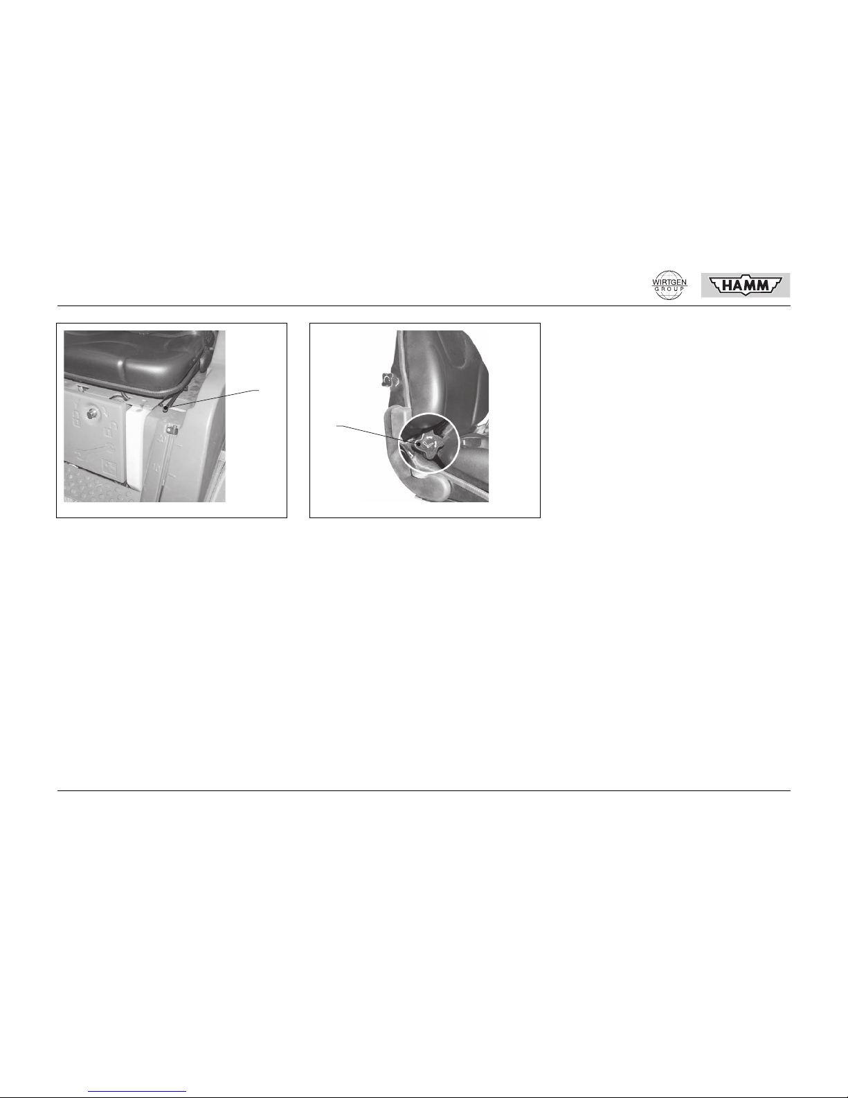
520 Seat adjustment weight
In order to absorb impulsive machine movements using the installed attenuation system,
this must be adjusted to the weight of the driver. The pretension of the attenuation system
can be adjusted continuously to a driver's
weight between 50 kg (110 lbs) and
120 kg (265 lbs) by turning the hand wheel to
the left or to the right.
0503-108
A
0504-104
MIN
MAX
0520-104
520
OPERATION
40 © HAMM AG 2009
521 Seat adjustment forward - backward
After lifting the lever, the upper part of the seat
can be shifted in forward or backward direction
in increments of 15 mm (0.59").
522 Seat adjustment backrest
The inclination of the backrest can be adjusted
in forward or backward direction by turning the
handwheel.
0521-103
521
0522-103
522

© HAMM AG 2009 41
OPERATION
2.2 DRIVING
2.2.1 General
What must be done prior to start of work?
• Perform control and maintenance works
(see maintenance section).
• Keep step-on surfaces and driver's stand
free from stumbling hazards, grease, dirt,
ice etc.
• Check the turning lights (303) and warning
lights (305), as well as the signal horn
(301) and the illumination (307).
• Check the parking br ake (304) .
•
• Never drive the machine until the fuel tank
is empty. Check the filling level of the fuel
tank in time. Fill up fuel tank in the
evening; this avoids the precipitation of
condensed water in the empty tank.
Fill up to the lower edge of the f ill i ng spout.
Only use clean fuel!
• Check the filling level of the water t ank. Fill
up to the lower edge of the filling spout.
Use clean water only!
Danger of accidents by operating errors!
Prior to every start-up:
Check the machine for operational and
traffic safety!
Read and observe the operating instructions and the safety notes!
Danger of explosion and increased fire
hazard during fuel handling!
Only fill up fuel when the engine is at a
standstill. Do not smoke during the fillingup process!
Never fill up fuel near open flames or igniting sparks. Do not fill up fuel in closed
rooms!
Notes on filling up fuel, see section “Fuel”.

OPERATION
42 © HAMM AG 2009
Symbols for operating substances
The filling places for operating substances on
the machine are identified with symbols. According to machine type and equipment, the
following symbols are attached to the machine:
A Fuel
B Water irrigation
C Additive irrigation
02460-13
A
B
C

© HAMM AG 2009 43
OPERATION
2.2.2 Precaution measures prior to
machine start
The machine may only be started and driven
by specialist persons authorised to do so.
Danger of accidents and danger of injuries!
The operator must get familiar to the working environment at the place of utilisation
prior to the start of work. The worki ng environment includes e.g. obstacles in the
working and traffic area, the load carrying
capacity of the underground and necessary safeguarding towards public traffic.
Make yourself familiar with all devices and
operating elements of the machine and the
function of these. It is too late to do this
during work.
Ensure that nobody is in front of, under, or
behind the machine. Do not allow anybody
to stay in the danger zone of the machine.
Ensure sufficient sight, adjust necessary
mirrors correctly.
Keep operation and safety signs clean. Illegible or lost signs must be replaced immediately.
After maintenance and repair work requiring a removal of the driver's cabin/ROPS
anti-rollover device, the driver's cabin/
ROPS anti-rollover device must be
screwed again securely to the machine
frame. This is the only way to ensure the
roll-over protection.
After maintenance work, check that all
tools have been removed from the machine and that all protection devices have
been re-attached and are in protection position.
The diesel engine may only be started
from the driver's seat. The engi ne must not
be started by short-circuiting the electric
contacts at the starter.

OPERATION
44 © HAMM AG 2009
2.2.3 Start of engine
Initial position before start ing
Set the operating elements to their initial position prior to the start of the engine.
• Engine speed (504).............................MIN
• Driving lever (501).......................CENTRE
• Vibration (312) ..................................OFF
• Parking brake (304) ...................APPLIED
• EMERGENCY STOP
(NOT-STOP) (302) ...............................UP
Start of engine
• Engine speed (504)...................¼ to MAX
• Key switch (310)...............................0 → I
(Electrical system ON)
When the key switch is turned to position I, all
illuminated indicators light up shortly for function control purposes.
• Key switch........................................I → III
When the engine is running,
• the illuminated indicator for charging current (201)
• the illuminated indicator for engine oil
pressure (202)
must go out.
Danger of intoxication!
Combustion engines and fuel-operated
heating systems may only be operated in
sufficiently ventilated areas. Take care for
sufficient ventilation prior to starting.
Engine starting with maximum engine
speed can lead to engine damage or damage at the hydraulic system.
The starting process may last 20 seconds
as a maximum; otherwise, the starter will
be overheated and destroyed. There must
be pauses between the individual starting
processes in order to allow the starter to
cool down. If the engine doesn't start after
two starting attempts, find out and eliminate the cause. Observe the instruction
manual of the engine.
The engine cannot be started by towing,
because the hydrostatic drive acts as a
brake when the feeding pressure is missing. Drive component damage would be
the consequence.
Only when the driving lever is in centre position, is the start connected to the key
switch via the starter protection device.
This is the only way to start the engine.
15000-10
302 310
504 503
501

© HAMM AG 2009 45
OPERATION
Before driveaway
• The acceleration and braking behaviour of
the machine are influenced by viscous hydraulic oil. In case of low external temperatures, in particular for temperatures below 0 °C (32 °F), wait a few minutes after
starting the engine until driveaway.
Warm up the machine during the warming
phase with moderate speed and low load
until the oil in the hydraulic system has
heated to 20 °C (68 °F).
• If the machine is fro zen to t he gr ound, t ake
care that no clods of earth stick to the
drum, as these could damage the scrapers. Therefore, park the machine on
planks or dry gravel if frost is likely!
Danger of accidents!
Always use safety belt!
Danger of falling!
For machines with driver's cabin, the lower
door parts must always be closed during
driving operation!
Always use safety belt!
Danger of accidents and danger of injuries!
It is forbidden to transport passengers.
Lift attached add-on devices off the
ground.
Prior to driveaway, check for persons in
the immediate vicinity of the machine.
In emergency situations and when there is
a danger, bring the machine to an immediate stop by operating the EMERGENCY
STOP switch (NOT-STOP).
Do not use the EMERGENCY STOP
switch (NOT-STOP) as operation brake.
The driving speed must always correspond to the conditions of the surroundings.
With increasing power requirements, take
back the driving lever correspondingl y (decrease driving speed); otherwise, the engine could stall.
In case of malfunctions at the steering or
braking systems, immediately stop the machine and have the malfunctions eliminated.
Never leave the driver's stand during travel.
At borders of excavation pits and batters,
drive the machine in a way that it cannot
slide or tilt.
Always check for sufficient clearance
when passing underpasses, bridges, tunnels, overhead lines etc.
Do not use any working procedure that
would impair the stability of the machine.
Avoid sudden curves when driving upward
or downward slopes and during driving in
transversal direction so slopes (danger of
tilting).
The smooth surface of the drums decreases lateral stability in case of wet, uneven
ground. Operation of the machine is not
admitted on snow and ice.

OPERATION
46 © HAMM AG 2009
2.2.4 Driving
• Engine speed (504)...........................MAX
• Parking brake (304)...............RELEASED
• Driving lever (501) ..............to the FRONT
or .........................................to the BACK
2.2.5 Driving with vibration
When the vibration system is switched on, the
drum will vibrate according to the speed of the
vibrator. This hammering wil l increa se the compacting force of the machine several times
over.
Vibration may only used at maximum diesel
engine speed and can be operated as single or
double vibration.
An elastic suspension of the drums prevents
the transfer of vibration oscillations to the machine frame.
If intensive compacting with few transitions
shall be obtained during earth-moving work,
the machine must roll over the material to be
compacted with low driving speed and excite
and compact it with the correspon ding frequency.
Only when the driver is on his/her seat an d
the driving lever is in centre position, will
driving operation be possible.
Do not switch off the key switch (310) during travel (key position 0).
15000-10
302 310
504 503
501
Danger of collapse!
Vibration must not be used in the immediate vicinity of buildings or bridges as these
can be damaged or destroyed by the vibration oscillation.
Danger of explosion!
Prior to switching on the vibration function,
it must be ensured that lines laid in the underground (gas, water, sewage, electricity
lines) cannot be damaged or destroyed by
the vibration oscillations.
Danger of falling!
The oscillating drum decreases road adhesion. When driving on hard surfaces, and
in particular when driving in transversal direction to slopes, lateral stability is decreased.

© HAMM AG 2009 47
OPERATION
When pushbutton (316) is pressed, the vibrato r
in the front drum, in the rear drum, or in both
drums, is preselected.
This illuminated indicator (symbol withou t oscil lation) indicates a pre-selected vibrator in case
of de-activated vibration. Each actuation of the
pushbutton switches one step ahead in the circulation.
Front vibrator........................................PRESS
Rear vibrator ............................PRESS AGAIN
Double vibrator.........................PRESS AGAIN
If the vibration system is activated with pushbutton (312), the illuminated indicator changes
over to Vibration activated (symbol with oscillation).
Activation .............................................PRESS
Deactivation .............................PRESS AGAIN
When the vibration system is activated, the vibrator can be switched on or off at any time
with the pushbutton at the multifunctional grip
(503).
The pushbutton (319) sets the operating mode
for the vibration system. The vibrator can be
switched on or off manually or automatically.
Manually...............................................PRESS
(Upper control light lights up)
The vibration can be switched on or off at any
time with the pushbutton on the multifunctional
grip (503).
Automatically............................PRESS AGAIN
(Lower control light lights up)
The switching on and off of the vibrat io n is coupled to the road speed. When the admissible
road speed with vibration (8 km/h (4.97 mph))
is exceeded, vibration is switched off.
Braking
(below 1.5 km/h (0.93 mph)) ..................... OFF
Acceleration
(more than 0.5 km/h (0.31 mph)) ...............ON
Driving
(more than 8.0 km/h (4.97 mph)) ..............OFF
The vibration can be switched on or off at any
time with the pushbutton on the multifunctional
grip.
15000-10
302 310
504 503
501
The automatic mode must be activated
with the pushbutton at the multifunctional
grip (503) after initial switching on.

OPERATION
48 © HAMM AG 2009
2.2.6 Stop, switch off engine, leave
machine
Stop
• Vibra tion (312) ..................................OFF
• Driving lever (501).......................CENTRE
The hydrostatic drive brings the machine to a
stop.
Before switching off the engine
• Vibration (312) ..................................OFF
• Parking brake (304) ...................APPLIED
• Engine speed (504).............................MIN
• Fully lower at t ached acces sory equ ipment .
Switch off engine
• Key switch (310) ...............................I → 0
Leaving the machine
The driver may only leave the machine when
orderly parked. Traffic regulations have to be
observed as well.
Before leaving the machine, the driver must
ensure that
• the parking brake is applied (304), installed add-on devices are lowered, and
that the engine is shut off.
• the key switch (310) is in latch position 0
and the ignition switch is pulled off.
• the cabin doors or t he dashbo ard cove r, as
well as all cladding covers are locked.
• the machine is secured against rolling
away with a wedge, in particular on
slopes.
• the machine does not obstruct the traffic
on public roads. If this cannot be avoided,
set up warning signs (illumination) according to safety regulations.
Danger of accidents and danger of injuries!
When leaving the driver's stand, even for
only a short time, the driver must shut
down the engine!
Carry out maintenance work only when th e
engine is stopped!
15000-10
302 310
504 503
501
Do not switch off engine from full load operation, instead, let it run for 1-2 minutes
with idle speed for temperature compensation purposes.
When the engine is at a standstill and the
electric system is switched on for a longer
period (key position I), the battery discharges rapidly.
Danger of falling!
Do not park the machine on batters or batter edges. Do not park the machine on
loose or shortly dumped ground. On
slopes, always park the machine on the
hillside and secure it against rolling away
with a wedge.

© HAMM AG 2009 49
OPERATION
2.2.7 Operation monitoring
Observe the control and indication instruments
on the dashboard from time to time.
If an illuminated indicator or the Diagnostic
Code indicator indicates a malfunction, find out
and eliminate the cause.
If an acoustic signal sounds, immediately shut
down the engine.
Check the filling level for operating substances
(fuel, water, additive). Fill up tanks in time.
Never drive the machine until the fuel tank is
empty.
The alternator is driven by a drive belt. If the
drive belt tears, the battery charging current is
interrupted. The illuminated indicator for charging current (201) lights up. Switch off the engine immediately to prevent battery discharge.
Replace defect drive belt by a new one.
Observe the following items in order to maintain a proper function of the alternator:
• Do not interrupt the connection between
battery and alternator when the engine is
running.
• Do not confuse battery connections.
• Remove the earthing strip from the battery
strip during welding work.
In order to protect electronic components as e.
g. central control unit, monitor unit, sensor s, relays etc., all connectors must be pulled out prior to welding work; otherwise, the electronic
components will be destroyed. The negative
pole must be applied directly to the constructive part to be welded. Take care for a good
contact!

OPERATION
50 © HAMM AG 2009
2.2.8 Towing
Towing of the machine assumes sufficient
knowledge of the functioning of the hydrostatic
drive and the operation of the spring locked
multiple disc brake. The preparations for towing may only be carried out by experienced
personnel who are aware of the dangers. The
machine may only be towed using the towing
points A and only with a towing bar. Replace
damaged pipes and hoses from which oil leaks
before towing (environment protection).
Before towing
• Driving lever (501).......................CENTRE
• Shut down diesel engine, if still functional.
• Secure machine against rolling away with
wedges or blocks.
• Separate the hydrostatic drive power train.
• Release parking brakes.
• Tow using towing bar only (brakes not
functional).
Towing
The machine may only be towed with the engine at a standstill and with low speed (1 km/h
(0.6 mph)). The maximum towing distance is
500 m (0.3 miles).
After towing
• Secure machine against rolling away with
wedges or blocks.
• Reconnect the hydrostatic drive power
train.
• Make parkin g brake oper ational.
• Remove towing bar.
Separate the hydrost atic drive power train
Only if the oil flow can circulate without pressure in the hydraulic system, can the machine
be towed.
• Loosen counternut A.
• Loosen Allen head screw B by three complete turns to the left.
10182-10
A
Do not screw out the screw by more than
three turns out of the housing; otherwise,
hydraulic oil may flow out between screw
and housing or air may enter into the system.
15016-10
B
A

© HAMM AG 2009 51
OPERATION
Reestablish the hydrostatic dri ve power
train
• Screw in the Allen head screw until the
stop.
• Tighten the counternut.
Making the parking brakes inoperational
• Apply the articulated frame steering blocking.
• Loosen screw A and screw out by hand
until a resistance can be noted (approximately 5 turns).
• Release the spring-operated brakes by
turning the steering wheel to the left until
increased turning power is required.
During towing, the spring-operated brakes
must be kept open by repeated releasing with
the steering wheel due to interior leaks.
Make parking brake operational
• Screw in screw A up to the valve seat
(max. 30 Nm).
• Release the articulated frame steering
blocking.
Danger of accidents!
The brake is out of function! The pretensioning power of the spring-operated
brakes may only be reduced for towing
purposes.
10085-10 15115-10
A

OPERATION
52 © HAMM AG 2009
2.2.9 Water irrigation
The pressure irrigation ensures a reliable
moistening of the drums during blacktop works
and thus prevents bituminous materials from
adhering to the drums. An electric water pump
supplies the irrigation system with water so
that the water consumption can be optimally
adjusted to the deployment conditions using
the installed automatic irrigation system. A
multilevel automatic interval system determines the minimum use of water for optimum
drum moisturing, using a combination of spray
quantity and pump pause time. The water
pump can also be switched manually to continuous operation at any time. The water irrigation
control is switched off at a road speed of less
than 0.5 km/h (0.31 mph). A high-volume, rustproof water filter, arranged upstream the water
pump, prevents a premature contamination of
pump, lines and spraying nozzles, thus ensuring a trouble-free operation. The filter maintenance depends on the purity of the water used.
The automatic water irrigation system is
switched on with pushbutton (317), for which
the illuminated indicator (232) shows the current irrigation level. As long as the pushbutton
is pressed, the pump runs in continuous operation. The pushbuttons (373) allow to increase
(+) or decrease (-) water consumpti on. The il luminated indicator (207) indicates that the water
pump is supplying.
Spray nozzle check when engine is at a
standstill
The following preconditions must be met for a
functional check of the spray nozzles during
machine standstill:
• EMERGENCY STOP switch
(NOT-STO P) (302)........................PRESS
• Parking brake (304) ...................APPLIED
• Engine stopped
• Electrical system (310).........................ON
• Driving lever (501) max.......to the FRONT
• Pushbutton (317).................................ON
If these preconditions are met, the water pump
runs in interval operation with the selected irrigation level.
When the machine is at a standstill, the interval irrigation system is without function.
15000-10
302 310
504 503
501

© HAMM AG 2009 53
OPERATION
To switch off:
• Pushbutton (317)...............................OFF
• Driving lever (501).......................CENTRE
• EMERGENCY STOP switch
(NOT-STOP) (302)............................... UP
On risk of frost
Frozen water leads to damage to the irrigation
system. Therefore, it must be drained before
frost begins.
• Screw up filter head A at the water tank
and remove it together with the pressure
spring (observe sealing ring on filter head) .
• Pull the filter insert from the water tank.
• Unscrew lateral collar nut from the spray
nozzles C and remove together with valve
seat B and membrane. Reassemble
spraying nozzle after emptying the nozzle
casing.
• Clean filter insert, pressure spring, and filter head and store in tool cabinet.
• Re-fit fil ter insert, pressure spring and fil ter
head only before starting work.
10088-10
A
15002-10
C
B

MAINTENANCE
54 © HAMM AG 2009
3 MAINTENANCE
3.1 INTRODUCTION
3.1.1 General
This machine requires care and maintenance
like any other technical device. The extent and
the frequency of the maintenance work depends essentially of the operating and deployment conditions, which are very different in
many cases. In case of more difficult operating
conditions, the machine must have maintenance in shorter intervals as sche duled for nor mal operation.
The maintenance intervals are determined according to the running time of the operation
hours counter; for this, additional maintenance
work has to be performed during the running-in
time according to the running-in regulations.
The works necessary for care and the conservation of the operational safety of the machine
are listed in the following sections. The running-in regulations, the maintenance intervals
and the care measures for the diesel engine
can be found in the operating instructions of
the engine manufacturer and must be observed.
Specialist knowledge is necessary for the execution of some inspection and maintenance
works; these cannot be given in the scope of
these operating instructions. We recommend
to have these works performed by trained specialised staff.

© HAMM AG 2009 55
MAINTENANCE
3.1.2 Notes on spare parts ordering
Notes on spare parts ordering
The components of a HAMM roller are deliberately selected by our engineers. If you use
original HAMM spare part s exclusi vely, you can
be sure that your roller will bring ultimate performance and best use.
Please contact an agency in your area; only
here can you find original HAMM spare parts
which guarantee quality.
If you wish, our customer service network can
put installers at your disposition who are familiar with the machine and the latest enhancements.
Ordering data
• Name and address of company
• Machine type and VIN
• Image No. and designation of the image or
text page of the spare parts list
• Part No., designation and required quantity
• Shipment address, i. e. station post office
of destination, if the spare parts are not to
be delivered to your company site but instead to a construction site
• Specification on dispatch type, i.e. railway
express etc.
Customer service
A world-wide, small-meshed network of authorised dealers and service stations ensures a
fast, flawless and high-quality HAMM customer
service.
If you use this service you can benefit from important advantages:
• Proper repair
• Trained mechanics
•Fast repair
• Short downtime of your machine
• Guarantee an work performed
• Guarantee on installed original HAMM
spare parts
in other words: low cost, best service in return.
In order to have your HAMM roller always
optimally operative, we recommend that
you keep the necessary maintenance
parts listed in 3.2.2 always in stock.

MAINTENANCE
56 © HAMM AG 2009
3.1.3 Safety
Carry out maintenance work only when the engine is stopped. Only open the engine hood
when the engine is at a standstill. Keep away
from moving, rotating or revolving parts; do not
touch these (danger of accidents).
Only perform oil change when the engine has
operating temperature. Danger of burning or
scalding.
Perform maintenance works on the engine exclusively according to the operating instructions of the manufacturer.
Any work in the danger area of the articulated
frame steering may only be performed with the
engine at a standstill and with the electric system switched off. Prior to start of work, pull off
the key from the battery disconnector (if existing). If a battery disconnector doesn't exist, remove the earthing strap from the battery (danger of life). If the machine is equipped with a
locking device for the articulated frame steering, it must be latched prior to start of work.
The machine must stand on level ground for
the control of liquid levels or for the change of
liquids (fuel, oil, refrigerant, water). This is the
only way to enable an exact determination of
liquid quantities.
In order to protect electronic components as e.
g. central control unit, monitor unit, sen sors, re lays etc., all connectors must be pulled out pri-
or to welding work; otherwise, the electronic
components will be destroyed. The negative
pole must be applied directly to the constructive part to be welded. Take care for a good
contact!
Articulated frame steering blocking device latched
Articulated frame steering blocking device released
Danger of accidents and danger of injuries!
Observe safety and accident prevention
regulations.
Only appropriate and clean lubricants may
be used. Otherwise the guarantee becomes void.
10085-10
10084-10

© HAMM AG 2009 57
MAINTENANCE
3.1.4 Use of biologic hydraulic oil
The hydraulic system of the machine is generally filled with mineral oil in factory. All maintenance intervals given in these maintenance instructions are related to mineral oil.
The use of biological hydraulic oil is admissible
under the following circumstances:
• Only biological oil on the basis of special
synthetic saturated complex esters may
be used. The products used and recommended by HAMM can be taken from the
lubricant indications 3.2.2. Other oils used
must correspond to the specifications of
the oil above mentioned. The neutralisation value (oil acid) may not be bigg er than
2.
• When the hydraulic oil is changed (biological oil replaces mineral oil or vice versa),
all filters in the oil circuit must be changed
after 50 operating hours. After that, the filter change intervals given in this instructions apply again.
• Used biological oil must be disposed at a
reliable place of disposal, just like mineral
oil.
3.1.5 Refrigerant conditioning
For liquid-cooled engines, special care must
be taken for the conditioning and the control of
the refrigerant; otherwise, corrosion, cavitation
and freezing can cause motor damage.
The conditioning of the refrigerant is performed
by adding a cooling system protection agent to
the refrigerant.
The cooling system requires constant monitoring. Apart from the control of the refrigerant
level, this also implies the verification of the
concentration of the cooling system protection
agent.
The concentration of the cooling system protection agent can be done with commercially
available test devices (example: gefo
glycomat ®).
The concentration of the cooling system protection agent in the refrigerant should not exceed or fall short of the following values:
/i
The products used and recommended by
HAMM (free from nitrites, amines and phosphates) can be taken from the lubricant indications 3.2.2. The factory-filled refrigerant mixture consist of 40 % cooling system protection
agent and 60 % water. This guarantees freezing protection up to -25 °C (-13 °F). The cooling system protection agent can be purchased
from the HAMM customer service, ordering
No. 313238.
The use of the cooling system protection agent
offers effective protection against corrosion,
cavitation and freezing.
Cooling system protection agent Water
max. 45 Vol. % 55 %
min. 35 Vol. % 65 %

MAINTENANCE
58 © HAMM AG 2009
3.2 LUBRICATION
INDICATIONS
3.2.1 Viscosity - temperature range
The viscosity of lubricant oil changes with the
temperature. The ambient temperature at the
place of utilisation determines the selection of
the viscosity class (SAE class).
The chart only applies to engine oil.
/i
02452-10
30
25
20
15
10
5
0 °C
-5
-10
-15
-20
-25
-30
SAE 0W-30
SAE 0W-40
SAE 5W-30
SAE 5W-40
SAE 10W-30
SAE 10W-40
SAE 15W-40
SAE 20W-50
nur mit Vorwärmen
only with engine preheater
seulement avec préchauffage moteur
Quality Viscosity Identification
Engine oil
The oil quality must correspond to the
API classification.
CG-4 or higher see chart
Hydraulic oil
Viscosity is determined according to
DIN standard 51519
(ISO-VG: viscosity grade).
HLP
Conditions
VG 22 arctic
VG 32 winter
VG 46 summer
VG 68 tropical
VG 100 extreme heat
Special oil
Only HAMM special oil is admissible.
Order No. 1238051
Gear oil with Limited Slip additions.
The oil quality must correspond to the
API classification.
API GL-5 SAE 85W-90
Refrigerant for liquid-cooled engines.
Mixture: 40 % refrigerate concentrate, 60 % water.
Lubricating grease
Lithium soaped multipurpose grease with high-pressure additives.
Temperature application range -25 °C (-13 °F) - +120 °C (+248 °F)

© HAMM AG 2009 59
MAINTENANCE
3.2.2 Lubricants used in delivery status
The machine is delivered with the products listed below. These products have been extensively tested by HAMM prior to their release and should be
used preferably. If products of other manufacturers shall be used, they must be equivalent to the products listed below with respect to quality and viscosity!
/i
Identification Designation Quality Viscosity
Designation of
manufacturer
Manufacturer
Engine oil
261149
API SAE 15W-40 Delvac MX MOBIL
Hydraulic oil (mineral oil)
261165
HLP ISO VG 46 AZOLLA AF 46 TOTAL
Hydraulic oil (biological
hydraulic oil)
1229028
synthetic, saturated
complex ester
ISO VG 46 Panolin HLP Synth 46 PANOLIN
Special oil
1238051
1238051 HAMM
Gear oil
261157
API GL-5 SAE 85W-90 EP-B 85W-90 TOTAL
Engine refrigerant
313238
free from nitrite, amine and
phosphate
Thermofreeze plus TOTAL
Lubricating grease
261858
lithium soaped multipur-
pose grease with high-pres-
sure additives
Multis EP2 TOTAL

60 © HAMM AG 2009
MAINTENANCE
3.3 MAINTENANCE OVERVIEW
3.3.1 Maintenance plan
/i
Observe the maintenance intervals of the running-in regulations 3.4!
Engine maintenance: see operating instructions for engine!
Point of maintenance Monitoring
see section
once every 10
operating hours
see section
once every 250
operating hours
see section
once every 500
operating hours
see section
once every 1000
operating hours
see section
once every 2000
operating hours
see section
Operation monitoring 3.5.1
Dry air filter 3.5.2 A 3.6.2
Hydraulic oil A 3.6.3 D 3.9.1
Refrigerant A 3.6.4 D 3.9.2
EMERGENCY STOP
(NOT-STOP)/parking brake
A 3.6.5
Water filter B 3.6.6
Spray nozzles B 3.6.7
Articulated frame steering joint C 3.7.1
Steering cylinder rod C 3.7.2
Radiator A 3.7.3
Scraper A 3.7.4
Filter insert hydraulic system D 3.8.1
Preliminary fuel filter D 3.8.2
Water irrigation insta lla tion B 3.9.3
A = check, B = clean, C = grease, D = replace

© HAMM AG 2009 61
MAINTENANCE
3.3.2 Required maintenance parts HD 8 VV, HD 10C VV (3W35)
H1700001 ⇒ H1701269
/i
3.3.3 Maintenance parts (Service kits) HD 8 VV, HD 10C VV (3W35)
/i
Quantity Maintenance part
first time
after
maintenance intervals in operating hours
once every
250
once every
500
once every
1000
once every
2000
4.0 l (1.06 US gal.) Engine oil 50 D D D D D
26.0 l (6.86 US gal.) Hydraulic oil D
5.5 l (1.45 US gal.) Refrigerant D
1 V-belt Alternator 2035686 ADD
2 Air filter cartridge 1302272 ADDD
1 Filter cartridge Lubricating oil 2044150 50 D D D D
1 Filter cartridge Fuel 1302191 50 D D D D
1 Preliminary fuel filter 2027225 50 D D D D
1 Seal Valve cover 2035675 50 D D D D
1 Filter insert Hydraulic system 2038889 50 D D D D
1 Filter insert Water filter 2033909 A
A = check, replace if necessary, D = replace
1 All required maintenance parts for the corresponding maintenance intervals 2044219 2044220 2044221 2044222

62 © HAMM AG 2009
MAINTENANCE
3.3.4 Required maintenance parts HD 8 VV, HD 10C VV (3W35)
H1701270 ⇒
/i
3.3.5 Maintenance parts (Service kits) HD 8 VV, HD 10C VV (3W35)
/i
Quantity Maintenance part
first time
after
maintenance intervals in operating hours
once every
250
once every
500
once every
1000
once every
2000
4.0 l (1.06 US gal.) Engine oil 50 D D D D D
26.0 l (6.86 US gal.) Hydraulic oil D
5.5 l (1.45 US gal.) Refrigerant D
1 V-belt Alternator 2035686 ADD
2 Air filter cartridge 1302272 ADDD
1 Filter cartridge Lubricating oil 2044150 50 D D D D
1 Filter cartridge Fuel 2057140 50 D D D D
1 Preliminary fuel filter 2027225 50 D D D D
1 Seal Valve cover 2035675 50 D D D D
1 Filter insert Hydraulic system 2038889 50 D D D D
1 Filter insert Water filter 2033909 A
A = check, replace if necessary, D = replace
1 All required maintenance parts for the corresponding maintenance intervals 2057805 2057806 2057807 2057808

© HAMM AG 2009 63
MAINTENANCE
3.4 RUNNING-IN REGULATIONS
(see also engine operating instructions)
3.4.1 After 50 operating hours
Diesel engine maintenance
• Replace lubricating oil
• Replace lubricating oil filter cartridge
• Replace fuel filter cartridge
• Replace preliminary fuel filter cartridge
• Check valve clearance
Maintenance of hydraulic installation
• Replace hydraulic oil filter

MAINTENANCE
64 © HAMM AG 2009
3.5 OPERATION MONITORING
(see also engine operating instructions)
3.5.1 Operation monitoring
When the electric system is switched on with
the key switch (310), all illuminated indicators
are activated for approx. 2seconds for function
control purposes. Check whether all illuminated indicators are operable. Observe the cont rol
and indication instruments from time to time. If
a illuminated indicator indicates a failure, determine and remove the cause. You can find an
exact description of the elements in the operating instructions, section 2.1.3.
3.5.2 Dry air filter
The operability of the air filter is monitored by
an electric contamination indicator. Only if the
illuminated indicator (203) flashes must the air
filter cartridge be replaced (see maintenance
once every 10 operating hours).

© HAMM AG 2009 65
MAINTENANCE
3.6 MAINTENANCE ONCE EVERY 10 OPERATING HOURS
(see also engine operating instructions)
3.6.1 Maintenance points at the
engine for engine oil change
The running-in regulations, the maintenance
intervals and the care measures for the diesel
engine can be found in the operating instructions of the engine manufacturer and must be
observed.
• A Oil filling spout
• B Oil dipstick
• C Oil drain screw
3.6.2 Check and clean dry air filter
The operability control of the ai r fi lt er cart ridges
must be performed prior to start of work with
the diesel engine running.
• Shortly rev up the diesel engine to maximum speed.
If the illuminated indicator (203) does not light
up, both filter cartridges are still completely operable. If the illuminated indicator flashes, both
air filter cartridges must be replaced. Observe
the engine operation instructions!
Replacement of air filter cartridges
• Open the clamps A at the air filter housing
and and remove dust collector B in upward
direction.
• Check seals, replace if necessary.
Only lubricants with this identification are
admissible, see lubricant indications 3.2.
15003-10
B
A
C
15004-10
C
AB

MAINTENANCE
66 © HAMM AG 2009
• Clean the inside of the dust col lectors.
• Replace air filter cartridges C.
• Install in reverse order.
3.6.3 Control of oil level in the
hydraulic oil tank
• Perform this control only when the engine
is cold.
• Unscrew purge filter A.
• Correct oil level: Between the Min. and
Max. there is a mark on the dipstick which
applies when the purge filter is screwed in
Do not exceed this o il le v e l!
• Fill in appropriate oil if the oil level is low.
• In case of bigger oil losses, find out and
eliminate the cause.
3.6.4 Control of refrigerant level for
engine cooling system
• Only check the refrigerant level when the
engine is cold.
• Correct refrigerant level: Between the Min.
and Max. mark at the compensation tank.
• In case of a lack of refrigerant, only fill up
refrigerant with the specified concentration.
• In case of bigger refrigerant losses, find
out and eliminate the cause.
Only lubricants with this identification are
admissible, see lubricant indications 3.2.
15114-10
MAX
MIN
A
Only lubricants with this identification are
admissible, see lubricant indications 3.2.
15072-10

© HAMM AG 2009 67
MAINTENANCE
3.6.5 Control of parking brake and
EMERGENCY STOP function
(NOT-STOP)
• Apply parking brake (304).
• Push the driving lever (501) shortly in forward direction.
If the drive blocks, the parking brake works
properly. If the machine moves even if the
parking brake is applied, the brake must be inspected or replaced.
• Press the EMERGENCY STOP switch
(NOT-STOP) (302). The drive doesn't react to movements of the driving lever
(501).
• Bring the machine to its ini tial positi on (see
control and operating elements No. 302).
3.6.6 Clean the water filter for the
pressure irrigation system
• Unscrew the filter head A at the water
tank.
• Pull the filter insert with the pressure
spring out of the water tank and clean it.
Re-assemble in reverse order.
Danger of accidents and danger of injuries!
For this maintenance work, the drive must
be actuated. Take care that nobody stays
in the danger zone of the machine. Observe safety regulations!
Only trained specialised staff may perform
works at the parking brake!
Call your customer service for works at the
parking brake!
15000-10
302 310
504 503
501
10088-10
A

MAINTENANCE
68 © HAMM AG 2009
3.6.7 Cleaning the spay nozzles
• Loosen the collar nut A and remove it together with spray nozzle B and filter C.
• Remove the filter and the spray nozzle
from the collar nut and clean them.
• Unscrew collar nut D.
• Remove valve insert E and membrane F.
• Flush the casing G with the wat er irr iga tion
system switched on.
Re-assemble in reverse order.
05316-10
DGE F
C
B
A

© HAMM AG 2009 69
MAINTENANCE
3.7 MAINTENANCE ONCE EVERY 250 OPERATING HOURS
(see also engine operating instructions)
Perform all maintenance work as described
under 10 operating hours. Additionally:
3.7.1 Lubricate articulated frame
steering joint
• Lubricate lubricating nipple A.
3.7.2 Lubrication of steering cylinder
rod
• Lubricate lubrica ti ng nipple A.
Danger of injuries!
Any work in the danger area of the articulated frame steering may only be performed with the engine at a standstill and
with the electric system switched off. Furthermore, the articulated frame steering
blocking device must be latched.
Only lubricants with this identification are
admissible, see lubricant indications 3.2.
15005-10
A
Danger of injuries!
Any work in the danger area of the articulated frame steering may only be performed with the engine at a standstill and
with the electric system switched off! Furthermore, the articulated frame steering
blocking device must be latched.
Only lubricants with this identification are
admissible, see lubricant indications 3.2.
15006-10
A

MAINTENANCE
70 © HAMM AG 2009
3.7.3 Control of radiator
• Check the cooling fins of the radiators for
contamination.
If the cooling fins are contaminated they must
be cleaned thoroughly and immediately.
• Clean the radiator with a pressure washer.
3.7.4 Control of the scrapers
Check whether the scrapers have proper contact to the drums. Adjust if necessary.
• Loosen hexagon screws A.
• Push the scraper console to the drum until
the scrapers make contact.
• Tighten the hexagon screws.
15007-10 15008-10
A

© HAMM AG 2009 71
MAINTENANCE
3.8 MAINTENANCE ONCE EVERY 500 OPERATING HOURS
(see also engine operating instructions)
Perform all maintenance work as described
under 10 and 250 operating hours. Additionally:
3.8.1 Replacing the filter insert for the
hydraulic system
• Unscrew the cup-shaped housing.
• Pull the filter insert from the filter head and
replace with a new one.
• Clean the inside of the cup-shaped housing from dirt deposits, screw it back to the
filter head and tighten.
3.8.2 Replacing the preliminary fuel
filter
• Loosen the hose clamps B on both sides
and pull off the fuel hose from the used filter A.
• Plug on new the filter and tighten the hose
clamps. Observe the flow direction!
Danger of burning or scalding!
15121-10
Increased fire hazard during fuel handling!
Do not smoke! No open fire during works
at the fuel system! Catch spilling fuel, do
not let it seep away into the ground!
15009-10
BAB

MAINTENANCE
72 © HAMM AG 2009
Bleeding the fuel system:
To avoid damage to the diesel engine, the fuel
filter must be drained at the drain valve from
time to time depending on the water content in
the fuel.
Purging of the fuel system is performed by
starting the Diesel engine. For t his, sever al
starting attempts may be necessary. The
starting process may last 20 seconds as a
maximum; otherwise, the starter winding
will be overheated and destroyed. There
must be pauses of a minimum of one
minute between the individual starting
processes in order to allow the starter to
cool down.

© HAMM AG 2009 73
MAINTENANCE
3.9 MAINTENANCE ONCE EVERY 2000 OPERATING HOURS, AT LEAST ONCE A YEAR
(see also engine operating instructions)
Perform all maintenance work as described
under 10, 250 and 500 operating hours. Additionally:
General:
After longer standstill periods (e.g. winter)
perform the following maintenance works
prior to start of usage. Condensed water
and dirt deposits can impair the function of
the engine and of the hydraulic system.
3.9.1 Replacement of hydraulic oil
• Unscrew purge filter A.
• Screw out oil drain screw B at the bottom
of the oil tank and let the used oil dr ain out.
• Screw in oil drain screw and tighten.
• Fill up specified oil through filling spout.
• Correct oil level: Between the Min. and
Max. there is a mark on the dipstick which
applies when the purge filter is screwed in
Do not exceed this oil level!
• Start the engine, actuate driving lever
(501) with low engine speed until the drive
activates, furthermore actuate the steering.
• Pipes and hoses are filled with oil and
purged.
• Check oil level with the motor at a stand-
still, please fill up oil as necessary.
Danger of burning or scalding!
Do not use cleaning rag for cleaning!
Catch used oil in a receptacle and dispose
of properly! Do not let it seep away into the
ground!
15114-10
MAX
MIN
A
15010-10
B

MAINTENANCE
74 © HAMM AG 2009
• Check the hydraulic system for leaks.
3.9.2 Changing the refrigerant
• Open the cap A at the compensation tank
B.
• Screw out the drain screw at the bottom of
the radiator or remove the lower refrigerant hose from the radiator and let the refrigerant drain into a provided receptacl e.
• Drain the engine block C according to the
indications of the engine operating instructions.
• Screw in the plug screws tightl y.
Avoid subsequent damage! After a damage to the hydraulic system, with a foreign
object having entered the oil circuit, the
entire hydraulic system must be cleaned.
This work may only be performed by
trained specialised personnel! Call the
customer service!
After that, replace all suction filters, return
filters or pressure filters in the hydraulic
system after 50 and after 125 operating
hours.
Only lubricants with this identification are
admissible, see lubricant indications 3.2.
Never open the cap of the compensation
tank when the engine is hot!
Danger of burning or scalding by boiling
refrigerant!
It is absolutely necessary to observe the
engine operation instructions! Dispose of
refrigerant properly! Only change the refrigerant when the engine is cold!
15079-10
B
A
15012-10
C

© HAMM AG 2009 75
MAINTENANCE
• Open the hollow screw D of the purge line
at the engine block by three turns (do not
remove!). Hol d up the screw-in fi tting E at
the hexagon!
• Fill new, properly mixed refrigerant into the
filling spout A of the compensation tank,
until refrigerant spills from the hollow
screw.
• Tighten the hollow screw.
• Fill up refrigerant up to the max. mark of
the compensation tank B.
• Close the filling spout.
• Start the engine and bring it to operating
temperature (thermostat opens).
• Shut down the engine.
• Check refrigerant level when the motor is
cold, fill up as necessary.
• Correct refrigerant level: Between the Min.
and Max. mark at the compensation tank
B.
15013-10
DE
Only lubricants with this identification are
admissible, see lubricant indications 3.2.

MAINTENANCE
76 © HAMM AG 2009
3.9.3 Cleaning the water irrigation
system
• Remove the valve insert A with the mem-
brane as well as the spray nozzles B with
filter from the spray nozzle casing.
• Screw up filter head at the water tank and
remove it together with the pressure spri ng
(observe sealing ring on filter head).
• Pull the filter insert from the water tank.
• Clean water tank thoroughly with pressure
washer (if available) or water jet.
• Flush the spray nozzle housings and the
hoses.
Re-assemble in reverse order. Clean water filter and spray nozzles according to section 3.6.
3.9.4 Visual inspection of hydraulic
system
Check all lines, hoses and screwed connections regularly (at least once a year) for leaks
and visible damage. Damaged parts must be
replaced immediately. Further operation is inadmissible. Oil spurting out can lead to injuries
and fire.
See also section 2.2.9 Water irrigation in
the operating instructions.
15014-10
BA

© HAMM AG 2009 77
TABLES
4TABLES
4.1 DIAGNOSTIC CODE
/i
00 no malfunction
01 Reversing lights (option)
Short-circuit
03 Left working lamp (option)
Short-circuit
05 Right working lamp (option)
Short-circuit
07 Drum illumination (option)
Short-circuit
11 Left headlight (option)
Short-circuit
13 Right headlight (option)
Short-circuit
18 Rear vibration solenoid or amplitude solenoid
Short-circuit, line rupture
19 Rear vibration solenoid
Short-circuit, line rupture
21 EMERGENCY STOP solenoid (NOT-STO P) or
front vibration solenoid
Short-circuit, line rupture
22 EMERGENCY STOP solenoid (NOT-STOP)
Short-circuit, line rupture
23 Front vibration solenoid
Short-circuit, line rupture
26 Rotating beacon (option)
Short-circuit
27 Water irrigation pump
Line rupture
28 Water irrigation pump
Short-circuit
29 Alternator
Short-circuit, line rupture
30 Parking light
Short-circuit

TABLES
78 © HAMM AG 2009
Notes
 Loading...