


Wireless Access Point 300
802.11n Wireless with 4 Port 10/100 Switch
User Manual
HNW300APN
www.hamletcom.com

Wireless Access Point HNW300APN
User Manual 2
INDEX
1. Introduction..........................................................................................6
1.1 System Requirements....................................................................................................................... 6
1.2 Package Contents ............................................................................................................................. 6
2. Specification ........................................................................................ 7
2.1 LED Meaning ..................................................................................................................................... 7
2.2 Connectors......................................................................................................................................... 8
3. Installation & Setup .............................................................................9
3.1 Connection of Access Point.............................................................................................................. 9
4. Configuration Procedures ................................................................ 10
4.1 Windows 98SE/ME/2000/XP .......................................................................................................... 10
4.2 Windows Vista 32/64....................................................................................................................... 12
4.3 Windows 7 32/64 ............................................................................................................................. 15
5. Access Point Configuration .............................................................17
6. Connect Wirelessly............................................................................ 21
7. Web Configuration............................................................................. 23
7.1 Accessing the Web Interface.......................................................................................................... 23
8. Quick Setup........................................................................................24
8.1 Operation Mode Setup .................................................................................................................... 25
8.2 WAN Interface Setup ...................................................................................................................... 27
8.3 Wireless Basic Setup ...................................................................................................................... 32
8.4 Wireless Security Setup.................................................................................................................. 41
9. Operation Mode ................................................................................. 53
9.1 Setting Operation Mode .................................................................................................................. 53
10. Wireless Network............................................................................. 54
10.1 Basic Settings ................................................................................................................................ 54
10.2 Advanced Settings ........................................................................................................................ 56
10.3 Security .......................................................................................................................................... 57
10.4 Access Control .............................................................................................................................. 63
10.5 WDS settings ................................................................................................................................. 66
10.6 Mesh settings................................................................................................................................. 74
10.7 WPS ............................................................................................................................................... 83
10.8 Operations of AP - AP being an enrollee..................................................................................... 87
10.9 Operations of AP - AP being a registrar ...................................................................................... 96
10.10 Wireless Schedule .................................................................................................................... 100
11. LAN Interface .................................................................................101
11.1 LAN Interface Setup.................................................................................................................... 101
11.2 Changing the LAN IP address and subnet mask ...................................................................... 103
11.3 Show Client .................................................................................................................................. 105
12. WAN Interface ................................................................................106
12.1 Configuring Static IP connection ................................................................................................ 109
12.2 Configuring DHCP Client connection ......................................................................................... 111
12.3 Configuring PPPoE connection ..................................................................................................113
12.4 Configuring PPTP connection .................................................................................................... 115
12.5 Configuring L2TP connection .....................................................................................................117
12.6 Clone MAC Address.................................................................................................................... 118
13. Port Filtering .................................................................................. 120
13.1 Port filtering for TCP port 80 ....................................................................................................... 121

Wireless Access Point HNW300APN
User Manual 3
13.2 Port filtering for UDP port 53 ...................................................................................................... 122
14. IP Filtering ......................................................................................123
14.1 IP filtering for TCP with specified IP........................................................................................... 124
14.2 IP filtering for UDP with specified IP .......................................................................................... 125
14.3 IP filtering for both TCP and UDP with specified IP.................................................................. 126
15. MAC Filtering .................................................................................127
15.1 MAC filtering for specified MAC Address .................................................................................. 128
16. Port Forwarding ............................................................................. 129
16.1 Port Forwarding for TCP with specified IP ................................................................................ 130
16.2 Port Forwarding for UDP with specified IP ................................................................................ 131
17. URL Filtering ..................................................................................132
17.1 URL filtering for specified URL Address .................................................................................... 133
18. DMZ .................................................................................................134
18.1 DMZ Host IP Address ................................................................................................................. 135
19. VLAN ...............................................................................................136
20. QoS..................................................................................................137
21. Status .............................................................................................. 138
22. Statistics ......................................................................................... 139
23. Dynamic DNS .................................................................................140
23.1 Configure DynDNS...................................................................................................................... 142
23.2 Configure TZO ............................................................................................................................. 143
24. Time Zone Setting.......................................................................... 144
SNTP Server and SNTP Client Configuration settings ..................................................................... 144
25. Denial-of-Service ...........................................................................145
26. Log ..................................................................................................147
System Log .......................................................................................................................................... 147
27. Firmware Update............................................................................ 149
27.1 About firmware versions ............................................................................................................. 149
27.2 Manually updating firmware........................................................................................................ 149
28. Save/Reload Settings ....................................................................150
28.1 Save Settings to File ...................................................................................................................150
28.2 Load Settings from File ............................................................................................................... 152
28.3 Resetting to Defaults................................................................................................................... 153
29. Password ........................................................................................ 155
29.1 Setting your username and password ....................................................................................... 155
30. Logout............................................................................................. 157
A Configuring your Computers........................................................ 158
Configuring Ethernet PCs ................................................................................................................... 158
B IP Addresses, Network Masks, and Subnets .............................. 159
IP Addresses........................................................................................................................................ 159
Subnet masks ...................................................................................................................................... 160
C UPnP Control Point Software on Windows XP ...........................161
UPnP Control Point Software on Windows XP with Firewall............................................................ 161

Wireless Access Point HNW300APN
User Manual 4
D Troubleshooting............................................................................. 164
Troubleshooting Suggestions ............................................................................................................. 164
Diagnosing Problem using IP Utilities ................................................................................................ 165
E Glossary ..........................................................................................167

Wireless Access Point HNW300APN
User Manual 5
Dear Customer,
thanks for choosing an Hamlet product. Please carefully follow the instructions for its use and
maintenance and, once this item has run its life span, we kindly ask You to dispose of it in an
environmentally friendly way, by putting it in the separate bins for electrical/electronic waste, or to bring
it back to your retailer who will collect it for free.
Responsibility Statement
The European importer declares that this product is compliant with CE standards. Importer references
and contact details available on www.hamletcom.com in the “About Us” section.
The importer for Italy is:
Careca Italia S.p.A.
VAT number 02078660350
www.careca.com
In order to reduce paper consumption we only printed a concise version of CE declaration of conformity
and Quick installation guide.
Full compliance declaration and product documentation will be available contacting us at
info@hamletcom.com specifying product code and documentation required.
We inform You this product is manufactured with materials and components in compliance with RoHS
directives: 2002/95/CE; with RAEE Directives: 2003/96/CE, Italian Legislative Decree 2005/151 and
following EEC Directives: ETSI EN 300 328 V1.7.1 (2006-10), ETSI EN 301-489-17: V1.3.2 (2008-04),
ETSI EN 301-489-1: V1.8.1 (2008-04), IEC EN 60950-1: 2001 + A11: 2004, ETSI EN 300 386 V1.3.3
(2005-04).
CE Mark Warning
This is a Class B product. In a domestic environment, this product may cause radio interference, in
which case the user may be required to take adequate measures.
Trademarks
All trademarks and company names mentioned in this manual are used for description purpose only
and remain property of their respective owners.
Changes
The material in this document is for information only and subject to change without notice. While
reasonable efforts have been made in the preparation of this document to assure its accuracy, Hamlet
assumes no liability resulting from errors or omissions in this document, or from the use of the
information contained herein. Hamlet reserves the right to make changes or revisions in the product
design or the product manual without reservation and without obligation to notify any person of such
revisions and changes.

Wireless Access Point HNW300APN
User Manual 6
1. Introduction
The Hamlet HNW300APN is a 300Mbit Wireless Access Point based on IEEE 802.11n Wi-Fi standard with
a built in 4-port fast Ethernet Switch. It offers the easiest way to share and extend your high-speed
DSL/Cable Modem Internet connection, either with or without wires. Network Address Translation (NAT)
and VPN pass-through provide your network protection from hackers, while WEP and WPA encryption
guard your wireless network for maximum privacy.
1.1 System Requirements
• A computer with pre-installed ethernet adapter
• Pentium 200MHz processor or above
• Windows 98SE / Windows Me / Windows 2000 / Windows XP / Windows Vista and Windows 7
• 64MB of RAM or above
• 25MB free disk space
1.2 Package Contents
• 802.11n Wireless Access Point
• CD-ROM (Software & Manual)
• Quick Installation Guide
• Ethernet Cable (RJ-45)
• Power Adaptor
Wireless Access Point HNW300APN
User Manual 7
2. Specification
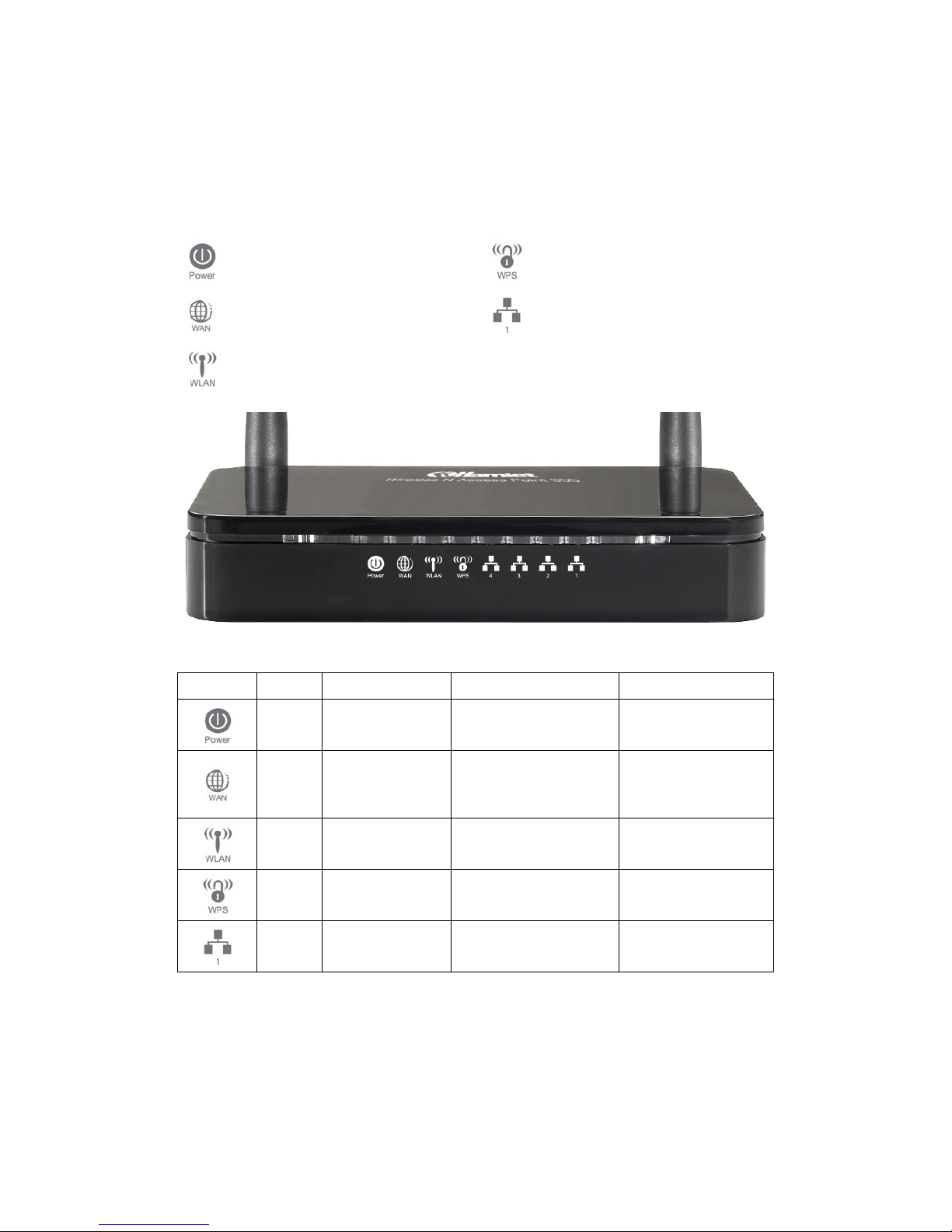
2.1 LED Meaning
The Access Point has indicator lights on the front side. Please see below for an explanation of the
function of each indicator light.
Power indicator
WPS Active indicator
WAN Active indicator
Ethernet Active indicator
Wireless Active indicator
Table 1. LED function
Label Color On Flash Off
Green Ready
Waiting for device
ready
Power Off
Green
The device has a
WAN IP address
from xDSL/Cable
Modem
Transmit / Receive
Data
No WAN IP address
from xDSL/Cable
Modem
Green WLAN Ready
Transmit / Receive
Data
WLAN Off
Green N/A
Start WPS peer within 2
minutes
WPS Idle
Green
Ethernet
Connected
Transmit / Receive
Data
Ethernet
Disconnected

Wireless Access Point HNW300APN
User Manual 8
2.2 Connectors
The below table shows the function of each connector and switch of the device.
CONNECTOR DESCRIPTION
ANTENNA ANTENNA
ON/OFF
SWITCH
Power on/off the device
POWER Connects to the supplied power cable
LAN 4/3/2/1 Connects the device via Ethernet to up to four PCs on your LAN
WAN Connects the device via Ethernet to xDSL / Cable Modem
WLAN Press this button for at least two full second to turn off/on wireless signals
WPS Press this button for at least three full seconds and the WPS LED will flash to start WPS.
Figure1. Rear View of the Wireless ADSL2+ Router
Figure2. WPS and WLAN button
Figure3. RESET button

Wireless Access Point HNW300APN
User Manual 9
3. Installation & Setup
Follow each step carefully and only go to the next step once you have completed the previous one.
Note: Be sure that you are well insulated from any power source to avoid electricity shock.
Note: Use only the manufacturer-approved power supply that shipped with the Access point.
1. Connect the power to the Access Point by plugging the power supply into an appropriate
electrical outlet.
2. If the Power LED is off, refer to “Troubleshooting” for information.
3.1 Connection of Access Point
1. Connect the supplied RJ45 Ethernet cable from your PC's Ethernet port to any of the 4 802.11n
Wireless Access Point's WAN Ports.
2. Connect the supplied RJ45 Ethernet cable from your xDSL/Cable Modem's Ethernet port to
802.11n Access Point's WAN Port.
3. Connect the power adapter to the power inlet “Power” of the 802.11n Access Point and turn the
power switch “ON/OFF Switch” of your 802.11n Access Point on.

Wireless Access Point HNW300APN
User Manual 10
4. Configuration Procedures
Before starting the Access Point configuration, please kindly configure the PC computer as below, to
have automatic IP address / DNS Server.
4.1 Windows 98SE/ME/2000/XP
1. Click on “Start” > “Control Panel” (in Classic View). In the Control Panel; double click on
“Network Connections” to continue.
2. Single right click on “Local Area connection”, then click “Properties”.
Wireless Access Point HNW300APN
User Manual 11
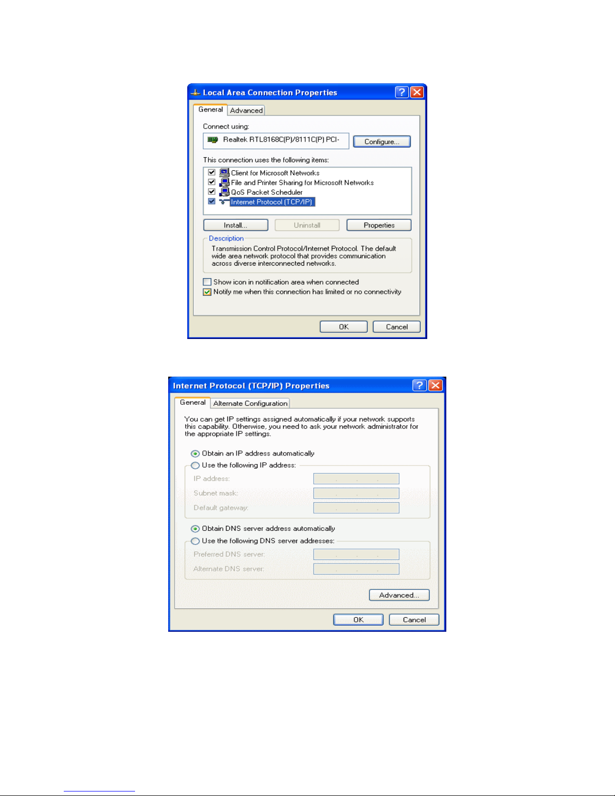
3. Double click on “Internet Protocol (TCP/IP)”.
4. Check “Obtain an IP address automatically” and “Obtain DNS server address automatically”
then click on “OK” to continue.
5. Click “Show icon in notification area when connected” (see screen image in 3. above) then
click on “OK” to complete the setup procedures.

Wireless Access Point HNW300APN
User Manual 12
4.2 Windows Vista 32/64
1. Click on “Start” > “Control Panel” > “Network and Sharing Center”.
2. In the Manage network connections, click on “Manage network connections” to continue.

Wireless Access Point HNW300APN
User Manual 13
3. Single right click on “Local Area connection”, then click “Properties”.
4. The screen will display the information “User Account Control” and click “Continue” to continue.
5. Double click on “Internet Protocol Version 4 (TCP/IPv4)”.

Wireless Access Point HNW300APN
User Manual 14
6. Check “Obtain an IP address automatically” and “Obtain DNS server address automatically”
then click on “OK” to continue.
Wireless Access Point HNW300APN
User Manual 15
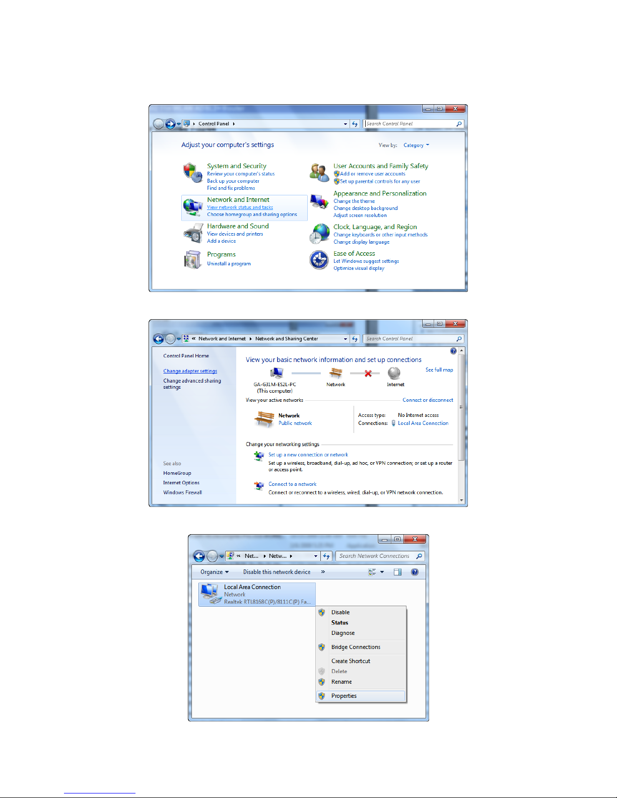
4.3 Windows 7 32/64
1. Click on “Start” > “Control Panel” (in Category View) > “View network status and tasks”.
2. In the Control Panel Home, click on “Change adapter settings” to continue.
3. Single right click on “Local Area Connection”, then click “Properties”.
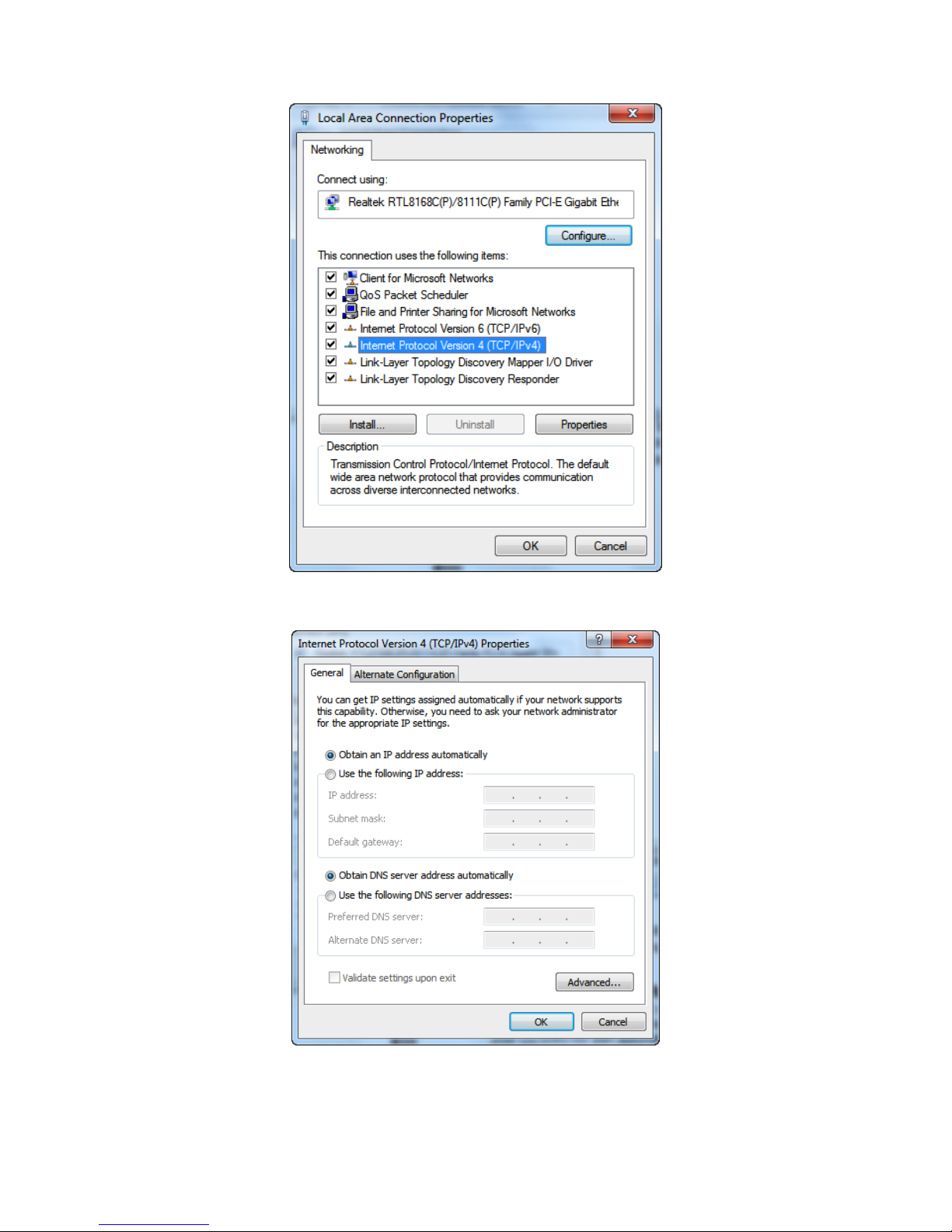
4. Double click on “Internet Protocol Version 4 (TCP/IPv4)”.
Wireless Access Point HNW300APN
User Manual 16
5. Check “Obtain an IP address automatically” and “Obtain DNS server address automatically”
then click on “OK” to continue.
Wireless Access Point HNW300APN
User Manual 17
5. Access Point Configuration
1. Please insert the supplied CD into your CD-ROM drive.
2. The CD should auto-start, displaying the window shown in 3 below. If your CD does not start
automatically, go to Windows Explorer, Select your CD drive and double click “autorun.exe”.
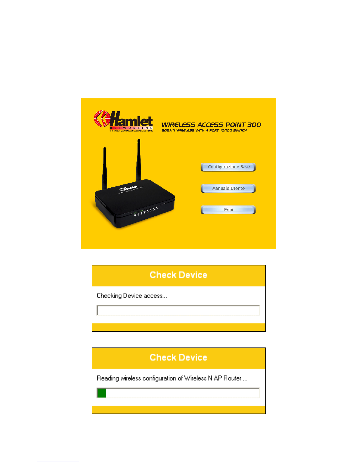
3. The screen below will appear. To configure the device, please click “Easy Configuration” button
and follow the steps illustrated in the following pages.
4. The Easy Configuration program is checking device access.
5. The Easy Configuration program is reading the wireless configuration.
Wireless Access Point HNW300APN
User Manual 18
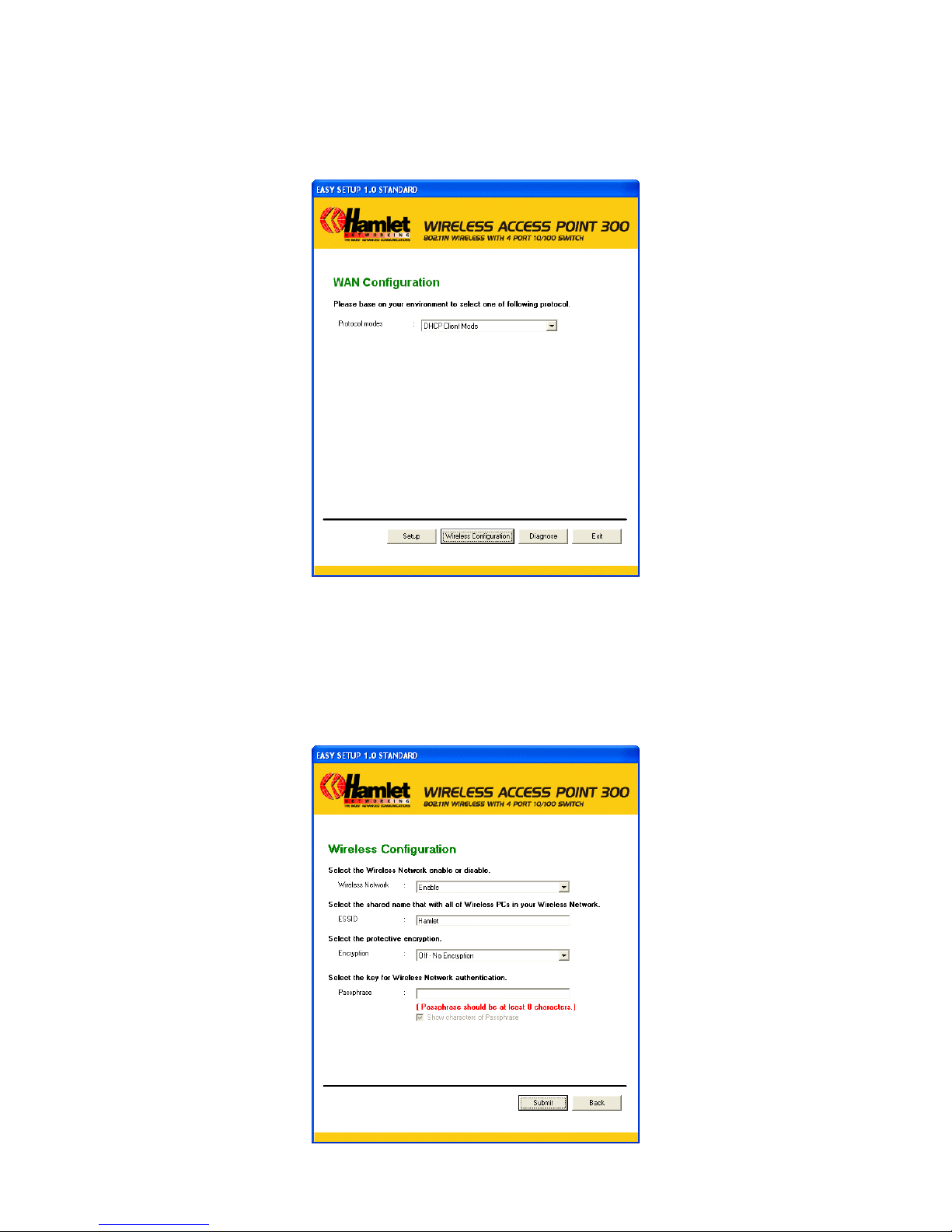
6. Select the Protocol mode Fixed IP, DHCP client or PPPoE Mode and enter related parameters that
your ISP (Internet Services Provider) or Network Administrator provided and then click “Wireless
Configuration“.
7. Please enter the “ESSID” if you want to change the default settings (Network= Enable, ESSID =
Hamlet).
8. Choose the Encryption type if necessary, as Off – No Encryption (Default) / 64 Bit Encryption /
128 Bit Encryption / Wi-Fi Protected Access (TKIP) / Wi-Fi Protected Access2 (AES-CCMP) and
WPA Mixed Mode. For example, you choose the WPA Mixed Mode type and configure
Passphrase.
9. Please click “Submit” button to continue.

Wireless Access Point HNW300APN
User Manual 19
10. Please click “Setup” button, when the procedure is completed, it will start to configure the device
for a while.
11. Now, checking Access Point hardware connection, Internet settings, WLAN settings, and
connection status.
12. Easy setup configuration completed. Click on "Close" to exit this program.

Wireless Access Point HNW300APN
User Manual 20
13. Click on "Exit" to exit this program.
14. Now, the Access Point has been configured completely, and suitable for Wireless and Internet
Connections.

Wireless Access Point HNW300APN
User Manual 21
6. Connect Wirelessly
Now that the Easy configuration setup is completed, you can connect wirelessly to your Wireless
Access Point. Follow the steps below to create a new wireless connection.
1. Double click on the wireless icon on your computer and search for the wireless network that you
enter ESSID name.
2. Click on the wireless network that you enter ESSID name to connect.
3. If the wireless network isn’t encrypted, click on “Connect Anyway" to connect.

Wireless Access Point HNW300APN
User Manual 22
4. If the wireless network is encrypted, enter the network key that belongs to your Encryption type and
Passphrase. You can later change this network key via the wireless configuration menu.
5. Click on "Connect" or "Apply".
Now, your wireless connection to the Access Point has been configured and you are able to connect to
ISP / Website.

Wireless Access Point HNW300APN
User Manual 23
7. Web Configuration
The embedded web configuration allows you to manage the Access Point from anywhere through a
common web browser such as Internet Explorer or Firefox. Please note that JavaScript must be
enabled.
7.1 Accessing the Web Interface
1. Make sure your Access Points properly connected.
2. Prepare your computer/computer network to connect to
the Access Point.
3. Launch your web browser and type
“http://192.168.1.254” in the address bar.
4. An Enter Network Password window displays. Enter the
user name (“admin” is the default), password (“hamlet” is
the default) and click OK.
5. You should now see the Status page of the Router.

Wireless Access Point HNW300APN
User Manual 24
8. Quick Setup
You can use “Quick Setup” to setup the Access Point as follows, and the Access Point will connect to
the Internet. From the left-hand menu, click on Quick Setup. The following page is displayed:
Figure 1: Quick Setup page

Wireless Access Point HNW300APN
User Manual 25
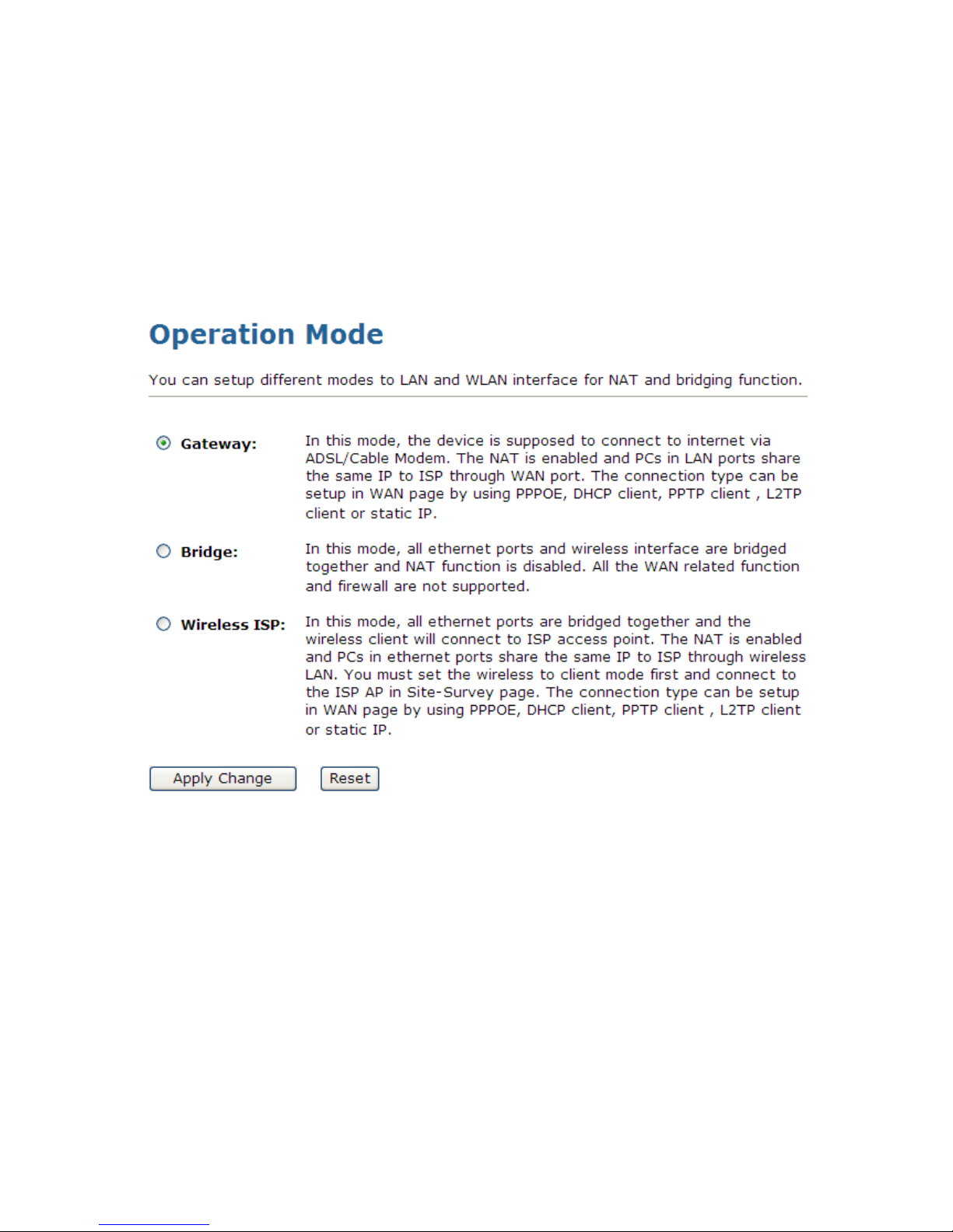
8.1 Operation Mode Setup
You can setup different modes to LAN and WLAN interface for NAT function.
Gateway
In this mode, the device is supposed to connect to internet via ADSL/Cable Modem. The NAT is enabled
and PCs in four LAN ports share the same IP to ISP through WAN port. The connection type can be setup
in WAN page by using PPPoE, DHCP client or static IP.
To change the Operation Mode:
1. From the left-hand menu, click on Quick Setup. The following page is displayed:
2. Click on the ratio of Gateway and then click on Next>>.

Wireless Access Point HNW300APN
User Manual 26
Wireless ISP
In this mode, all Ethernet ports are bridged together and the wireless client will connect to ISP access point.
The NAT is enabled and PCs in Ethernet ports share the same IP to ISP through wireless LAN. You must
set the wireless to client mode first and connect to the ISP AP in Site-Survey page. The connection type can
be setup in WAN page by using PPPOE, DHCP client or static IP.
To change the Operation Mode:
1. From the left-hand menu, click on Quick Setup. The following page is displayed:
2. Click on the ratio of Wireless ISP and then click on Next>>.
Wireless Access Point HNW300APN
User Manual 27
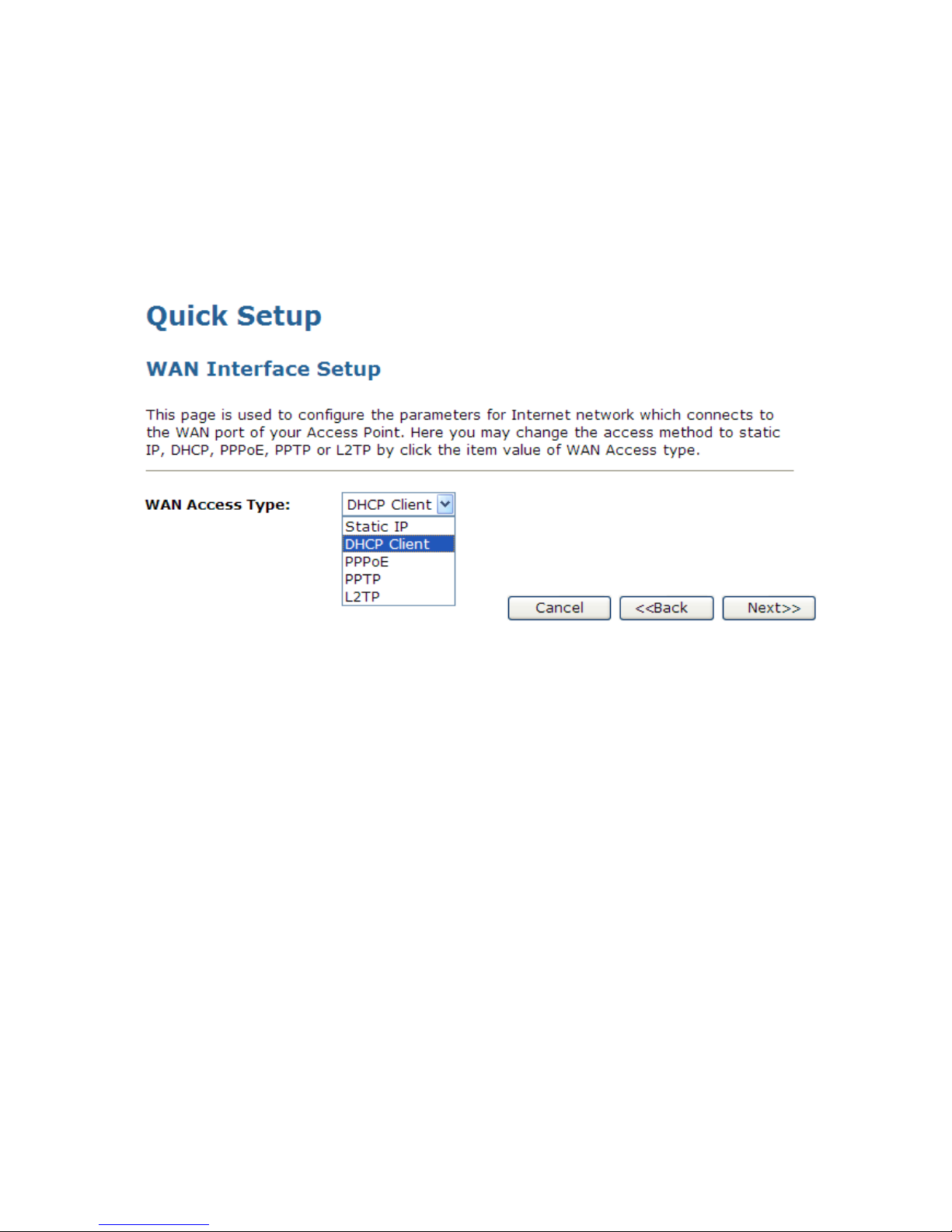
8.2 WAN Interface Setup
This page is used to configure the parameters for Internet network which connects to the WAN port of your
Access Point. Here you may change the access method to static IP, DHCP, or PPPoE by click the item
value of WAN Access type.
To change the WAN Access Type:
1. From the WAN Access Type drop-down list, select Static IP, DHCP Client, PPPoE, PPTP, or L2TP
setting determined by your Network Administrator or ISP.
2. Click Next>>.

Wireless Access Point HNW300APN
User Manual 28
Static IP
In this mode, the device is supposed to connect to internet via ADSL/Cable Modem. The NAT is enabled
and PCs in four LAN ports share the same IP to ISP through WAN port. The connection type can be setup
in WAN page by using static IP.
1. From the WAN Access Type drop-down list, select Static IP setting determined by your Network
Administrator or ISP.
2. Enter IP Address for example 172.1.1.1.
3. Enter Subnet Mask for example 255.255.255.0.
4. Enter Default Gateway for example 172.1.1.254.
5. Enter DNS for example 172.1.1.254.
6. Click Next>>.

Wireless Access Point HNW300APN
User Manual 29
DHCP Client
1. From the WAN Access Type drop-down list, select DHCP Client setting determined by your Network
Administrator or ISP.
2. Click Next>>.
PPPoE
1. From the WAN Access Type drop-down list, select PPPoE setting determined by your Network
Administrator or ISP.
2. Enter User Name for example 1234.
3. Enter Password for example 1234.
4. Click Next>>.

Wireless Access Point HNW300APN
User Manual 30
PPTP
1. From the WAN Access Type drop-down list, select PPTP setting determined by your Network
Administrator or ISP.
2. Enter Server IP Address for example 172.1.1.1 determined by your Network Administrator or ISP.
3. Enter User Name for example 1234 determined by your Network Administrator or ISP.
4. Enter Password for example 1234 determined by your Network Administrator or ISP.
5. Click Next>>.
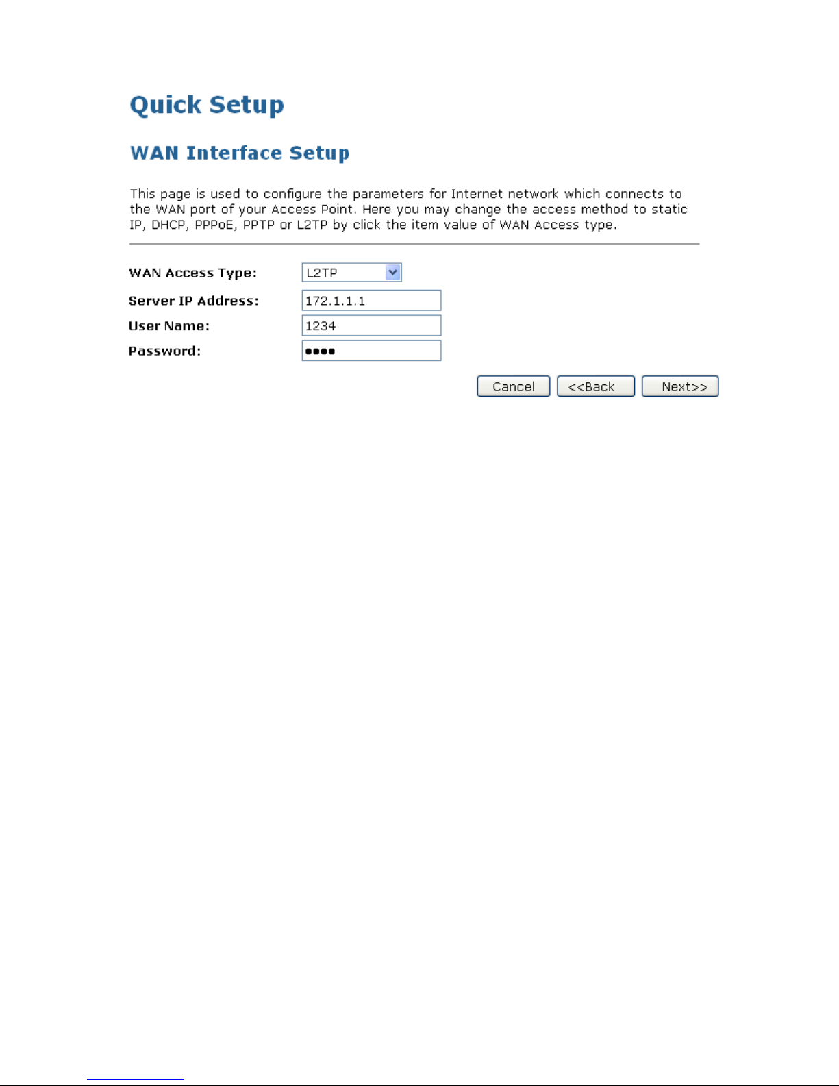
L2TP
1. From the WAN Access Type drop-down list, select L2TP setting determined by your Network
Administrator or ISP.
2. Enter Server IP Address for example 172.1.1.1 determined by your Network Administrator or ISP.
3. Enter User Name for example 1234 determined by your Network Administrator or ISP.
4. Enter Password for example 1234 determined by your Network Administrator or ISP.
5. Click Next>>.
Wireless Access Point HNW300APN
User Manual 31

Wireless Access Point HNW300APN
User Manual 32
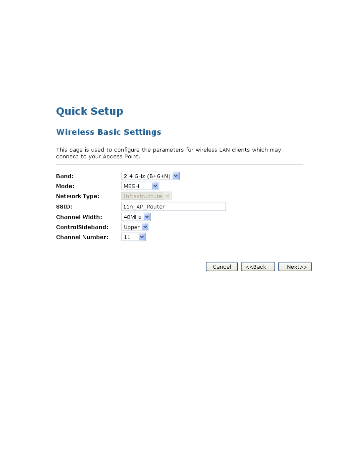
8.3 Wireless Basic Setup
This page is used to configure the parameters for wireless LAN clients which may connect to your Access
Point.

Wireless Access Point HNW300APN
User Manual 33
AP (Access Point)
Access Point is used to configure the parameters for wireless LAN clients who may connect to your Access
Point.
1. From the Band drop-down list, select a Band.
2. From the Mode drop-down list, select AP setting.
3. Enter SSID for example 11n_AP_Router.
4. From the Channel Width drop-down list, select a Channel Width.
5. From the ControlSideband drop-down list, select a ControlSideband.
6. From the Channel Number drop-down list, select a Channel Number.
7. Click Next>>.

Wireless Access Point HNW300APN
User Manual 34
Client
This page is used to configure the parameters for wireless LAN clients which may connect to your Access
Point.
1. From the Band drop-down list, select a Band.
2. From the Mode drop-down list, select Client setting.
3. From the Network Type drop-down list, select a Type.
4. Enter SSID for example 11n_AP_Router.
5. Click Next>>.

Wireless Access Point HNW300APN
User Manual 35
WDS (Wireless Distribution System)
WDS stands for Wireless Distribution System. It enables the access points (APs) to be connected
wirelessly. Integrated Access Device can also provide you services of WDS.
Note: Integrated Access Device that supports WDS does not support security systems like WEP, WPA or
WPA-Enterprise on a WDS network:
Sometimes you want to establish a multi-access point wireless network in your home or office, but you don’t
have Ethernet cabling running to the locations where you want to add the extra AP. After all, you may be
using wireless because you don’t have wires in place already.
One way to overcome this problem is to use a system built into Wireless Gateway that is known as Wireless
Distribution System (WDS).
WDS basically creates a mesh network by providing a mechanism for access points to “talk” to each other
as well as sending data to devices associated with them.
Note: WDS is based on some standardized 802.11 protocols, but there is no standardized way of
implementing it that works across different AP and router vendors. So if you have a Wireless Gateway in
one location and you want to create a WDS link to a other brand of router in another location (just to pick
two brands at random), you probably won’t be able to get it to work. You have your best luck when you use
equipment from the same manufacturer
Note: When you use WDS as a repeater system, as described below, it effectively halves the data rate for
clients connected to Integrated Wireless Gateway. That’s because every bit of data needs to be sent twice
(data is received by the AP and then retransmitted).
To configure WDS, you need to modify some settings on each AP within the network. Your exact steps (and
the verbiage used) will vary from vendor to vendor. Generally, you’ll see some settings like the following:

Wireless Access Point HNW300APN
User Manual 36
Main WDS station:
One of your WDS stations is the main base station for the WDS network. This AP is connected directly to
your Internet connection, or connected to your router via a wired connection. The main station is the bridge
to your Internet connection that all wireless traffic eventually flows through.
Repeater WDS stations:
In a simple, two-AP WDS network, the other “unwired” AP is a repeater. The repeater receives data from
the main base station and relays the data to the wireless clients associated to the repeater station (and vice
versa for data coming from the clients). If you have more than two APs, remote APs may be repeaters, or
they may be relays that provide an intermediate stopping point for data if the repeater is too far away from
the main station to communicate.
When you configure your main or base WDS station, take note of the channel you’re set to and the ESSID
or network name of your network. If your AP has any kind of channel auto configuration function that
changes channels based on network conditions, be sure to disable this feature. If your main WDS station is
also your network’s router, make sure it’s set up to distribute IP addresses in the network.
Note: Write down or otherwise take note of the MAC addresses of all of your WDS stations — many
configuration software systems require you to know these addresses to make the configuration settings
work. Write down the wireless MAC address (it’s often on a sticker) and not the Ethernet MAC address
Turn on the WDS functionality in your main station (it’s often labeled WDS, or may say something like
Enable This Base Station As a WDS Main Base Station — that’s the wording Apple uses for their AirPort
Extreme products). When you turn on this functionality, the configuration software may ask you to identify
the remote repeater(s). Have the MAC addresses of those repeaters handy in case you need them.
Depending upon how your software works, you may have to separately access the configuration software
on the remote repeater APs to turn on WDS. Here are a few things to remember:
• You need to assign any other WDS stations to the same channel that your main base station is
using. This is counterintuitive to many folks who have had the 802.11b/g “use channels 1, 6, and
11 and keep your APs on different channels” mantra driven into their heads for a long time!
• You set the ESSID of the remote location(s) using either a unique name or by using the same
ESSID as you use for your main base station. (Whoa, our heads just exploded!) Using the same
ESSID (a “roaming” network) is pretty cool. You associate with one AP one time and then your PC
or Mac can associate with any AP on your WDS network without you having to do anything — it’s
more seamless this way. But remember, you don’t have to do this — you can give each AP a
unique ESSID and just configure your computer to associate with them according to your
preference.
• Make sure you turn off any routing or DHCP functionality in the remote repeater stations. All of this
functionality should be performed in the main base station or the network’s main router.

Wireless Access Point HNW300APN
User Manual 37
WDS (Wireless Distribution System) only
1. From the Band drop-down list, select a Band.
2. From the Mode drop-down list, select WDS setting.
3. From the Channel Width drop-down list, select a Channel Width.
4. From the ControlSideband drop-down list, select a ControlSideband.
5. From the Channel Number drop-down list, select a Channel Number.
6. Click Next>>.

Wireless Access Point HNW300APN
User Manual 38
AP (Access Point) + WDS (Wireless Distribution System)
Access Point is used to configure the parameters for wireless LAN clients which may connect to your
Access Point.
1. From the Band drop-down list, select a Band.
2. From the Mode drop-down list, select AP+WDS setting.
3. Enter SSID for example 11n_AP_Router.
4. From the Channel Width drop-down list, select a Channel Width.
5. From the ControlSideband drop-down list, select a ControlSideband.
6. From the Channel Number drop-down list, select a Channel Number.
7. Click Next>>.
Wireless Access Point HNW300APN
User Manual 39
MESH only
1. From the Band drop-down list, select a Band.
2. From the Mode drop-down list, select MESH setting.
3. From the Channel Width drop-down list, select a Channel Width.
4. From the ControlSideband drop-down list, select a ControlSideband.
5. From the Channel Number drop-down list, select a Channel Number.
6. Click Next>>.

Wireless Access Point HNW300APN
User Manual 40
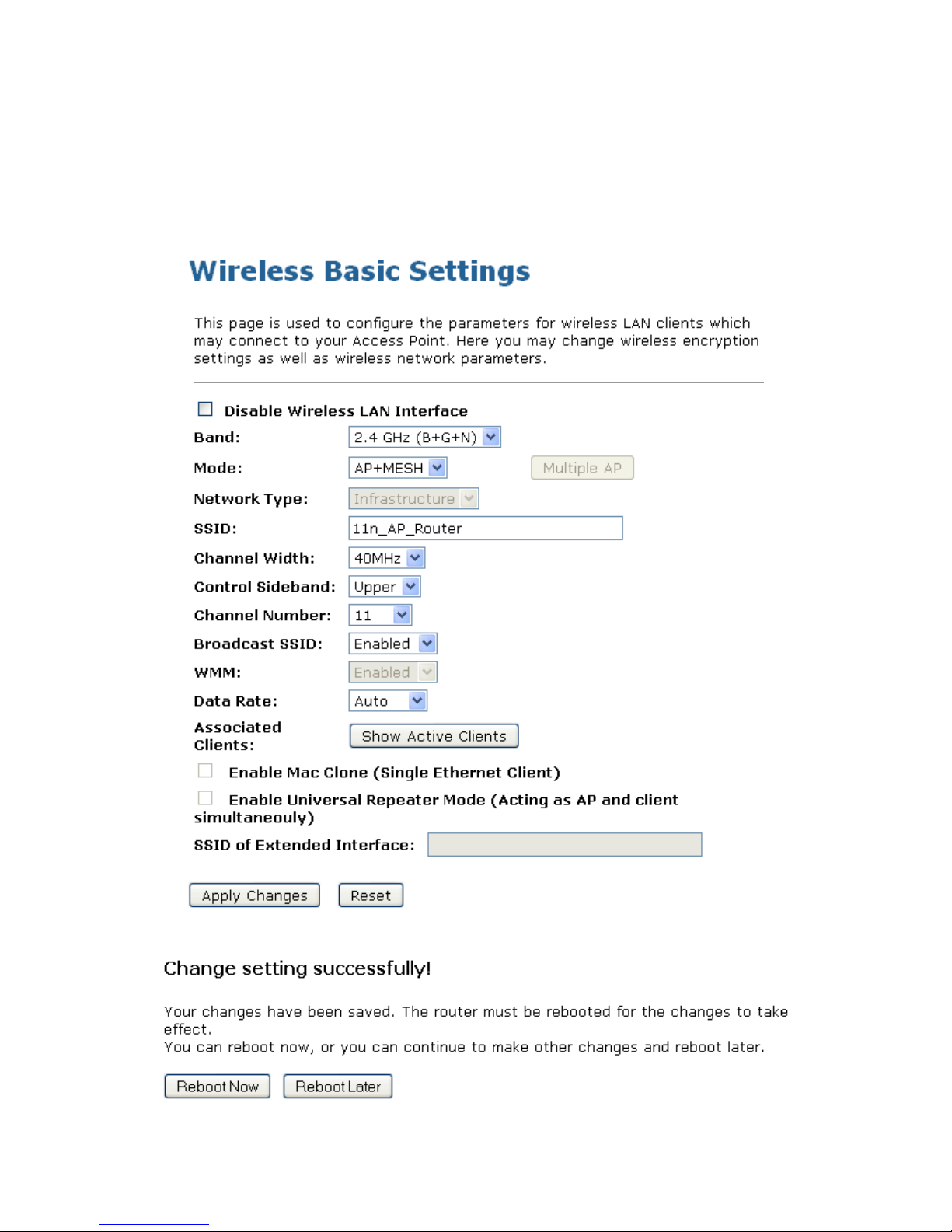
AP (Access Point) + MESH
Access Point is used to configure the parameters for wireless LAN clients which may connect to your
Access Point.
1. From the Band drop-down list, select a Band.
2. From the Mode drop-down list, select AP+MESH setting.
3. Enter SSID for example 11n_AP_Router.
4. From the Channel Width drop-down list, select a Channel Width.
5. From the ControlSideband drop-down list, select a ControlSideband.
6. From the Channel Number drop-down list, select a Channel Number.
7. Click Next>>.
Wireless Access Point HNW300APN
User Manual 41
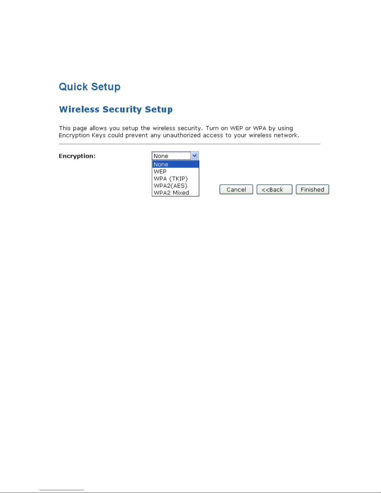
8.4 Wireless Security Setup
This page allows you setup the wireless security. Turn on WEP or WPA by using Encryption Keys could
prevent any unauthorized access to your wireless network.
You can protect your wireless data from potential eavesdroppers by encrypting wireless data transmissions.
An eavesdropper might set up a compatible wireless adapter within range of your device and attempt to
access your network. Data encryption is the translation of data into a form that cannot be easily understood
by unauthorized users.
There are two methods of wireless security to choose from:
• Wired Equivalent Privacy (WEP); data is encrypted into blocks of either 64 bits length or 128 bits length.
The encrypted data can only be sent and received by users with access to a private network key. Each
PC on your wireless network must be manually configured with the same key as your device in order to
allow wireless encrypted data transmissions. Eavesdroppers cannot access your network if they do not
know your private key. WEP is considered to be a low security option.
• Wi-Fi Protected Access (WPA); provides a stronger data encryption method (called Temporal Key
Integrity Protocol (TKIP)). It runs in a special, easy-to-set-up home mode called Pre-Shared Key (PSK)
that allows you to manually enter a pass phrase on all the devices in your wireless network. WPA data
encryption is based on a WPA master key. The master key is derived from the pass phrase and the
network name (SSID) of the device.
To configure security, choose one of the following options:
• If you do not want to use Wireless Network security, From the Encryption drop-down list, select None
setting and then click Finished. None is the default setting, but you are strongly recommended to use
wireless network security on your device.
• If you want to use WEP 64bit ASCII (5 characters) data encryption, follow the instructions in Configuring
64bit ASCII (5 characters) encryption.
• If you want to use WEP 64bit Hex (10 characters) data encryption, follow the instructions in Configuring
WEP 64bit Hex (10 characters) security.
• If you want to use WEP 128bit ASCII (5 characters) data encryption, follow the instructions in
Configuring WEP 128bit ASCII (5 characters) security.
• If you want to use WEP 128bit Hex (10 characters) data encryption, follow the instructions in
Configuring WEP 128bit Hex (10 characters) security.
• If you want to use WPA1 - Wi-Fi Protected Access 1 (TKIP) Passphrase encryption, follow the
instructions in Configuring WPA (TKIP) Passphrase security.
• If you want to use WPA1 - Wi-Fi Protected Access 1 (TKIP) HEX (64 characters) encryption, follow the
instructions in Configuring WPA (TKIP) HEX (64 characters) security.

Wireless Access Point HNW300APN
User Manual 42
• If you want to use WPA2 (AES) - Wi-Fi Protected Access 2 (AES) Passphrase encryption, follow the
instructions in Configuring WPA2 (AES) Passphrase security.
• If you want to use WPA2 (AES) - Wi-Fi Protected Access 2 (AES) HEX (64 characters) encryption,
follow the instructions in Configuring WPA2 (AES) HEX (64 characters) security.
• If you want to use WPA2 Mixed- Wi-Fi Protected Access 2 (Mixed) Passphrase encryption, follow the
instructions in Configuring WPA2 (Mixed) Passphrase security.
• If you want to use WPA2 Mixed- Wi-Fi Protected Access 2 (Mixed) HEX (64 characters) encryption,
follow the instructions in Configuring WPA2 (Mixed) HEX (64 characters) security.
Wireless Access Point HNW300APN
User Manual 43
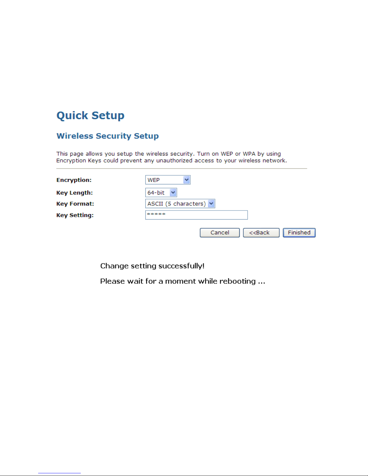
Configuring WEP 64bit ASCII (5 characters) security
The example set in this section is for 64bit encryption.
1. From the Encryption drop-down list, select WEP setting.
2. From the Key Length drop-down list, select 64-bit setting.
3. From the Key Format drop-down list, select ASCII (5 characters) setting.
4. Type the Key Setting.
5. Click Finished.
6. Change setting successfully! Please wait for a moment while rebooting.

Wireless Access Point HNW300APN
User Manual 44
Configuring WEP 64bit Hex (10 characters) security
The example set in this section is for 64bit encryption.
1. From the Encryption drop-down list, select WEP setting.
2. From the Key Length drop-down list, select 64-bit setting.
3. From the Key Format drop-down list, select Hex (10 characters) setting.
4. Type the Key Setting.
5. Click Finished.
6. Change setting successfully! Please wait for a moment while rebooting.

Wireless Access Point HNW300APN
User Manual 45
Configuring WEP 128bit ASCII (13 characters) security
The example set in this section is for 128bit encryption.
1. From the Encryption drop-down list, select WEP setting.
2. From the Key Length drop-down list, select 128-bit setting.
3. From the Key Format drop-down list, select ASCII (13 characters) setting.
4. Type the Key Setting.
5. Click Finished.
6. Change setting successfully! Please wait for a moment while rebooting.

Wireless Access Point HNW300APN
User Manual 46
Configuring WEP 128bit Hex (26 characters) security
The example set in this section is for 128bit encryption.
1. From the Encryption drop-down list, select WEP setting.
2. From the Key Length drop-down list, select 128-bit setting.
3. From the Key Format drop-down list, select Hex (26 characters) setting.
4. Type the Key Setting.
5. Click Finished.
6. Change setting successfully! Please wait for a moment while rebooting.

Wireless Access Point HNW300APN
User Manual 47
Configuring WPA (TKIP) Passphrase security
The example set in this section is for WPA (TKIP) Passphrase encryption.
1. From the Encryption drop-down list, select WPA (TKIP) setting.
2. From the Pre-Shared Key Format drop-down list, select Passphrase setting.
3. Type the Pre-Shared Key.
4. Click Finished.
5. Change setting successfully! Please wait for a moment while rebooting.
Wireless Access Point HNW300APN
User Manual 48
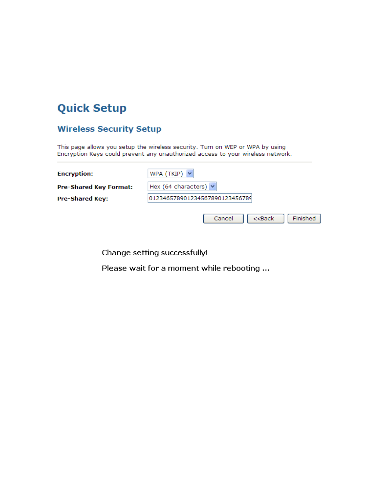
Configuring WPA (TKIP) HEX (64 characters) security
The example set in this section is for WPA (TKIP) HEX (64 characters) encryption.
1. From the Encryption drop-down list, select WPA (TKIP) setting.
2. From the Pre-Shared Key Format drop-down list, select HEX (64 characters) setting.
3. Type the Pre-Shared Key.
4. Click Finished.
5. Change setting successfully! Please wait for a moment while rebooting.

Wireless Access Point HNW300APN
User Manual 49
Configuring WPA2 (AES) Passphrase security
The example set in this section is for WPA2 (AES) Passphrase encryption.
1. From the Encryption drop-down list, select WPA2 (AES) setting.
2. From the Pre-Shared Key Format drop-down list, select Passphrase setting.
3. Type the Pre-Shared Key.
4. Click Finished.
5. Change setting successfully! Please wait for a moment while rebooting.

Wireless Access Point HNW300APN
User Manual 50
Configuring WPA2 (AES) HEX (64 characters) security
The example set in this section is for WPA2 (AES) HEX (64 characters) encryption.
1. From the Encryption drop-down list, select WPA2 (AES) setting.
2. From the Pre-Shared Key Format drop-down list, select HEX (64 characters) setting.
3. Type the Pre-Shared Key.
4. Click Finished.
5. Change setting successfully! Please wait for a moment while rebooting.

Wireless Access Point HNW300APN
User Manual 51
Configuring WPA2 (Mixed) Passphrase security
The example set in this section is for WPA2 (Mixed) Passphrase encryption.
The WPA2 (Mixed) Passphrase encryption supports both WPA (TKIP) and WPA2 (AES).
1. From the Encryption drop-down list, select WPA2 (Mixed) setting.
2. From the Pre-Shared Key Format drop-down list, select Passphrase setting.
3. Type the Pre-Shared Key.
4. Click Finished.
5. Change setting successfully! Please wait for a moment while rebooting.

Wireless Access Point HNW300APN
User Manual 52
Configuring WPA2 (Mixed) HEX (64 characters) security
The example set in this section is for WPA2 (Mixed) HEX (64 characters) encryption.
The WPA2 (Mixed) HEX (64 characters) encryption supports both WPA (TKIP) and WPA2 (AES).
1. From the Encryption drop-down list, select WPA2 (Mixed) setting.
2. From the Pre-Shared Key Format drop-down list, select HEX (64 characters) setting.
3. Type the Pre-Shared Key.
4. Click Finished.
5. Change setting successfully! Please wait for a moment while rebooting.
Wireless Access Point HNW300APN
User Manual 53
9. Operation Mode
This chapter describes how to configure the way that your device connects to the Internet. There are three
options of Operation Mode: Gateway, Bridge and Wireless ISP.
9.1 Setting Operation Mode
To change the Operation Mode:
1. From the left-hand Operation Mode menu. The following page is displayed:
2. Click on the ratio of Gateway, Bridge or Wireless ISP and then click on Apply to active it.

Wireless Access Point HNW300APN
User Manual 54
10. Wireless Network
This chapter assumes that you have already set up your Wireless PCs and installed a compatible Wireless
card on your device. See Configuring Wireless PCs.
10.1 Basic Settings
The Wireless Network page allows you to configure the Wireless features of your device. To access the
Wireless Network Basic Settings page:
From the left-hand Wireless menu, click on Basic Settings. The following page is displayed:
Figure 2: Wireless Network page

Wireless Access Point HNW300APN
User Manual 55
Field Description
Disable
Wireless LAN
Interface
Enable/Disable the Wireless LAN Interface.
Default: Disable
Band Specify the WLAN Mode to 802.11b/g Mixed mode, 802.11b mode or
802.11g mode
Mode Configure the Wireless LAN Interface to AP, Client, WDS, AP + WDS,
MESH or AP + MESH mode
Network Type Configure the Network Type to Infrastructure or Ad hoc.
SSID Specify the network name.
Each Wireless LAN network uses a unique Network Name to identify the
network. This name is called the Service Set Identifier (SSID). When you
set up your wireless adapter, you specify the SSID. If you want to
connect to an existing network, you must use the name for that
network. If you are setting up your own network you can make up your
own name and use it on each computer. The name can be up to 20
characters long and contain letters and numbers.
Channel Width Choose a Channel Width from the pull-down menu.
Control
Sideband
Choose a Control Sideband from the pull-down menu.
Channel
Number
Choose a Channel Number from the pull-down menu.
Broadcast SSID Broadcast or Hide SSID to your Network.
Default: Enabled
WMM Enable/disable the Wi-Fi Multimedia (WMM) support.
Data Rate Select the Data Rate from the drop-down list
Associated
Clients
Show Active Wireless Client Table
This table shows the MAC address, transmission, receiption packet
counters and encrypted status for each associated wireless client.
Enable Mac
Clone (Single
Ethernet Client)
Enable Mac Clone (Single Ethernet Client)
Enable
Universal
Repeater Mode
Acting as AP and client simultaneously
SSID of
Extended
Interface
When mode is set to “AP” and URM (Universal Repeater Mode ) is
enabled, user should input SSID of another AP in the field of “SSID of
Extended Interface”. Please note, the channel number should be set to
the one, used by another AP because 8186 will share the same channel
between AP and URM interface (called as extended interface hereafter).

Wireless Access Point HNW300APN
User Manual 56
10.2 Advanced Settings
These settings are only for more technically advanced users who have a sufficient knowledge about
wireless LAN. These settings should not be changed unless you know what effect the changes will have on
your Access Point. To access the Wireless Network Advanced Settings page:
From the left-hand Wireless menu, click on Advanced Settings. The following page is displayed:
Field Description
Fragment
Threshold
When transmitting a packet over a network medium, sometimes the
packet is broken into several segments, if the size of packet exceeds
that allowed by the network medium.
The Fragmentation Threshold defines the number of bytes used for the
fragmentation boundary for directed messages.
RTS Threshold RTS stands for “Request to Send”. This parameter controls what size
data packet the low level RF protocol issues to an RTS packet. The
default is 2347.
Beacon Interval Choosing beacon period for improved response time for wireless http
clients.
Preamble Type Specify the Preamble type is short preamble or long preamble
IAPP Disable or Enable IAPP
Protection A protection mechanism prevents collisions among 802.11g nodes.
RF Output
Power
TX Power measurement.

Wireless Access Point HNW300APN
User Manual 57
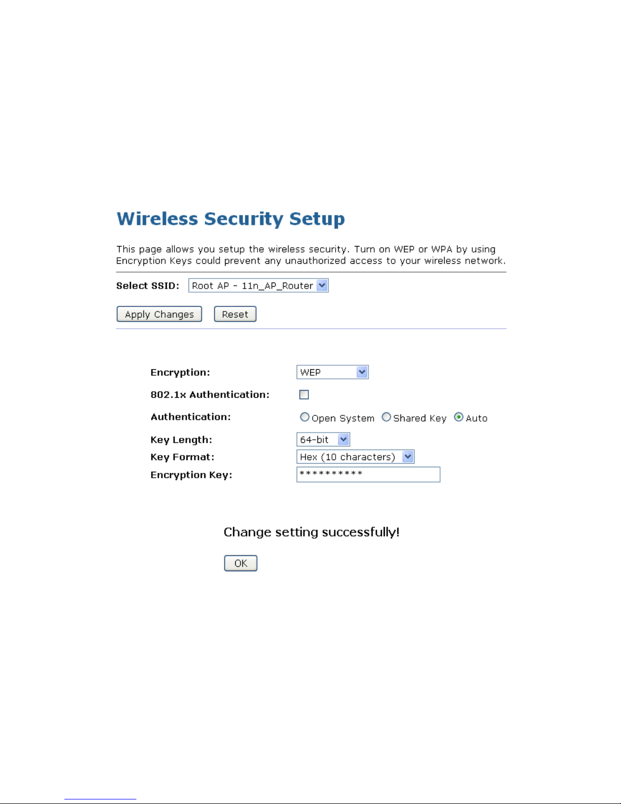
10.3 Security
This page allows you setup the wireless security. Turn on WEP or WPA by using Encryption Keys could
prevent any unauthorized access to your wireless network. To access the Wireless Network Security page:
From the left-hand Wireless menu, click on Security. The following page is displayed:
Field Description
Select SSID Select the SSID
Encryption Configure the Encryption to Disable, WEP, WPA , WPA2 or WPA-Mixed
Use 802.1x
Authentication
Use 802.1x Authentication by WEP 64bits or WEP 128bits
Authentication Configure the Authentication Mode to Open System, Shared Key or
Auto
Key Length Select the Key Length 64-bit or 128-bit
Key Format Select the Key Format ASCII (5 characters), Hex (10 characters), ASCII
(13 characters) or Hex (26 characters)
Encryption Key Enter the Encryption Key
WPA
Authentication
Mode
Configure the WPA Authentication Mode to Enterprise (RADIUS) or
Personal (Pre-Shared Key)
WPA Cipher
Suite
Configure the WPA Cipher Suite to TKIP and/or AES

Wireless Access Point HNW300APN
User Manual 58
Field Description
WPA2 Cipher
Suite
Configure the WPA2 Cipher Suite to TKIP and/or AES
Pre-Shared Key
Format
Configure the Pre-Shared Key Format to Passphrase or HEX (64
characters)
Pre-Shared Key Type the Pre-Shared Key
Enable
Pre-Authentication
According to some of the preferred embodiments, a method for
proactively establishing a security association between a mobile node
in a visiting network and an authentication agent in another network to
which the mobile node can move includes: negotiating
pre-authentication using a flag in a message header that indicates
whether the communication is for establishing a pre-authentication
security associatio
n; and one of the mobile node and the authentication
agent initiating pre-authentication by transmitting a message with the
flag set in its message header, and the other of the mobile node and the
authentication agent responding with the flag set in its message header
only if it supports the pre-authentication. Enable/disable
pre-authentication support. Default: disable.
Authentication
RADIUS Server
Port: Type the port number of RADIUS Server
IP address: Type the IP address of RADIUS Server
Password: Type the Password of RADIUS Server
Wireless Access Point HNW300APN
User Manual 59
WEP + Encryption Key
WEP aims to provide security by encrypting data over radio waves so that it is protected as it is transmitted
from one end point to another. However, it has been found that WEP is not as secure as once believed.
1. From the Encryption drop-down list, select WEP setting.
2. From the Key Length drop-down list, select 64-bit or 128-bit setting.
3. From the Key Format drop-down list, select ASCII (5 characters), Hex (10 characters), ASCII (13
characters) or Hex (26 characters) setting.
4. Enter the Encryption Key value depending on selected ASCII or Hexadecimal.
5. Click Apply Changes button.
6. Change setting successfully! Click on OK button to confirm and return.

Wireless Access Point HNW300APN
User Manual 60
WEP + Use 802.1x Authentication
WEP aims to provide security by encrypting data over radio waves so that it is protected as it is transmitted
from one end point to another. However, it has been found that WEP is not as secure as once believed.
1. From the Encryption drop-down list, select WEP setting.
2. Check the option of Use 802.1x Authentication.
3. Click on the ratio of WEP 64bits or WEP 128bits.
4. Enter the Port, IP Address and Password of RADIUS Server:
5. Click OK button.
6. Change setting successfully! Click on OK button to confirm and return.

Wireless Access Point HNW300APN
User Manual 61
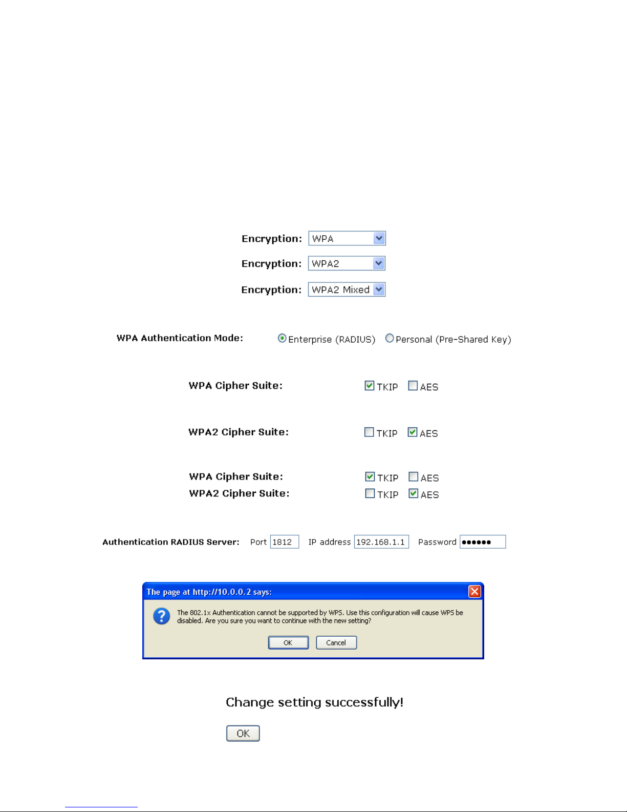
WPA/WPA2/WPA2 Mixed + Personal (Pre-Shared Key)
Wi-Fi Protected Access (WPA and WPA2) is a class of systems to secure wireless (Wi-Fi) computer
networks. WPA is designed to work with all wireless network interface cards, but not necessarily with first
generation wireless access points. WPA2 implements the full standard, but will not work with some older
network cards. Both provide good security, with two significant issues:
• Either WPA or WPA2 must be enabled and chosen in preference to WEP. WEP is usually presented as
the first security choice in most installation instructions.
• In the "Personal" mode, the most likely choice for homes and small offices, a pass phrase is required
that, for full security, must be longer than the typical 6 to 8 character passwords users are taught to
employ.
1. From the Encryption drop-down list, select WPA, WPA2 or WPA2 Mixed setting.
2. Click on the ratio of Personal (Pre-Shared Key).
3. Check the option of TKIP and/or AES in WPA Cipher Suite if your Encryption is WPA:
4. Check the option of TKIP and/or AES in WPA2 Cipher Suite if your Encryption is WPA2:
5. Check the option of TKIP and/or AES in WPA/WPA2 Cipher Suite if your Encryption is WPA2 Mixed:
6. From the Pre-Shared Key Format drop-down list, select Passphrase or Hex (64 characters) setting.
7. Enter the Pre-Shared Key depending on selected Passphrase or Hex (64 characters).
8. Click on Apply Changes button to confirm and return.
9. Change setting successfully! Click on OK button to confirm and return.
Wireless Access Point HNW300APN
User Manual 62
WPA/WPA2/WPA2 Mixed + Enterprise (RADIUS)
Wi-Fi Protected Access (WPA and WPA2) is a class of systems to secure wireless (Wi-Fi) computer
networks. WPA is designed to work with all wireless network interface cards, but not necessarily with first
generation wireless access points. WPA2 implements the full standard, but will not work with some older
network cards. Both provide good security, with two significant issues:
• Either WPA or WPA2 must be enabled and chosen in preference to WEP. WEP is usually presented as
the first security choice in most installation instructions.
• In the "Personal" mode, the most likely choice for homes and small offices, a pass phrase is required
that, for full security, must be longer than the typical 6 to 8 character passwords users are taught to
employ.
1. From the Encryption drop-down list, select WPA, WPA2 or WPA2 Mixed setting.
2. Click on the ratio of Enterprise (RADIUS).
3. Check the option of TKIP and/or AES in WPA Cipher Suite if your Encryption is WPA:
4. Check the option of TKIP and/or AES in WPA2 Cipher Suite if your Encryption is WPA2:
5. Check the option of TKIP and/or AES in WPA/WPA2 Cipher Suite if your Encryption is WPA2 Mixed:
6. Enter the Port, IP Address and Password of RADIUS Server:
7. Click OK button.
8. Change setting successfully! Click on OK button to confirm and return.
Wireless Access Point HNW300APN
User Manual 63
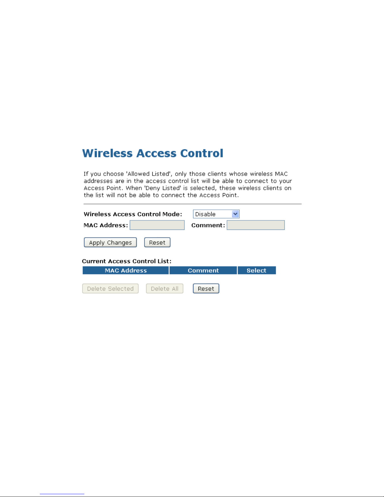
10.4 Access Control
For security reason, using MAC ACL's (MAC Address Access List) creates another level of difficulty to
hacking a network. A MAC ACL is created and distributed to AP so that only authorized NICs can connect
to the network. While MAC address spoofing is a proven means to hacking a network this can be used in
conjunction with additional security measures to increase the level of complexity of the network security
decreasing the chance of a breach.
MAC addresses can be add/delete/edit from the ACL list depending on the MAC Access Policy.
If you choose 'Allowed Listed', only those clients whose wireless MAC addresses are in the access control
list will be able to connect to your Access Point. When 'Deny Listed' is selected, these wireless clients on
the list will not be able to connect the Access Point. To access the Wireless Network Access Control page:
From the left-hand Wireless menu, click on Access Control. The following page is displayed:

Wireless Access Point HNW300APN
User Manual 64
Allow Listed
If you choose 'Allowed Listed', only those clients whose wireless MAC addresses are in the access control
list will be able to connect to your Access Point.
1. From the Wireless Access Control Mode drop-down list, select Allowed Listed setting.
2. Enter the MAC Address.
3. Enter the Comment.
4. Click Apply Changes button.
5. Change setting successfully! Click on OK button to confirm and return.
6. The MAC Address that you created has been added in the Current Access Control List.

Wireless Access Point HNW300APN
User Manual 65
Deny Listed
When 'Deny Listed' is selected, these wireless clients on the list will not be able to connect the Access
Point.
1. From the Wireless Access Control Mode drop-down list, select Deny Listed setting.
2. Enter the MAC Address.
3. Enter the Comment.
4. Click Apply Changes button.
5. Change setting successfully! Click on OK button to confirm and return.
6. The MAC Address that you created has been added in the Current Access Control List.
Wireless Access Point HNW300APN
User Manual 66
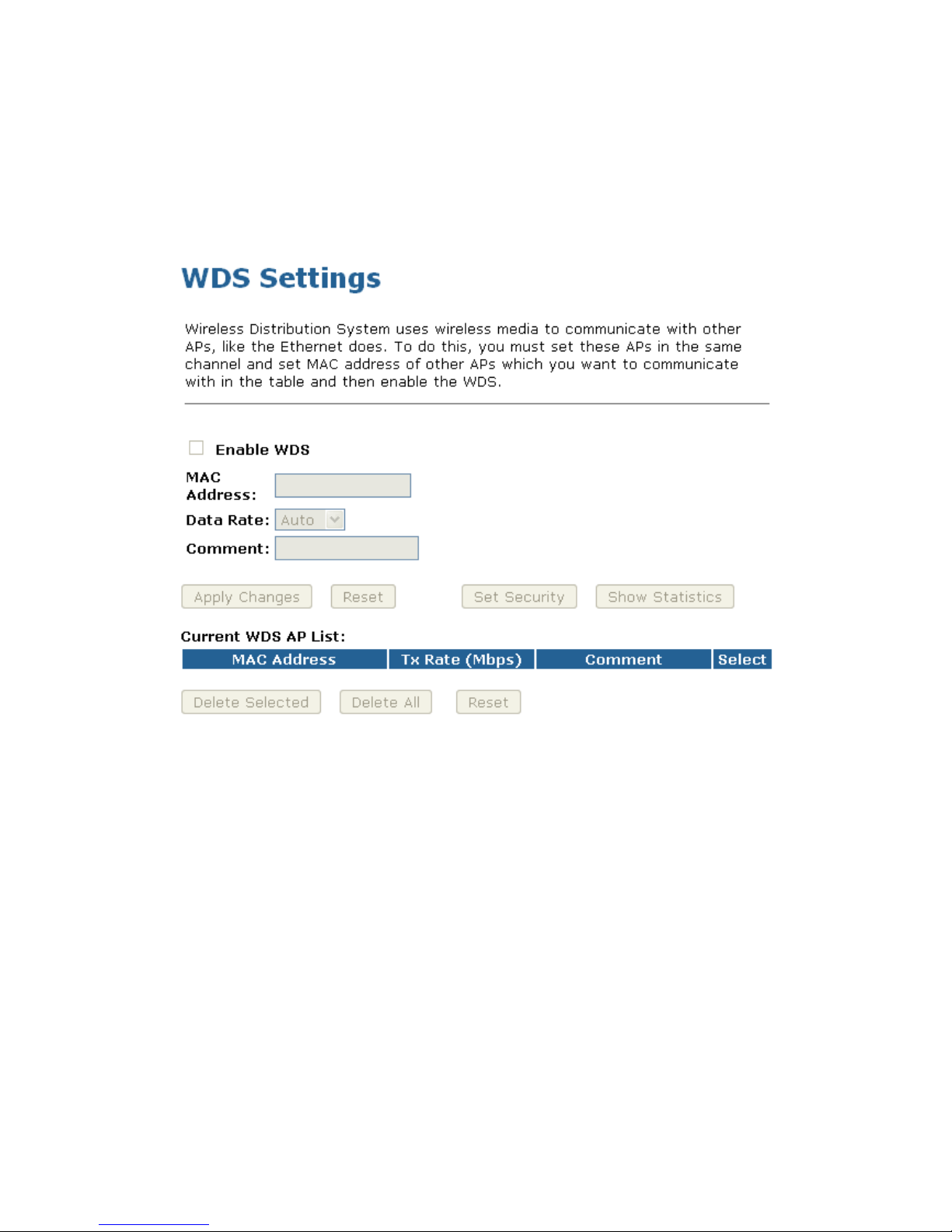
10.5 WDS settings
Wireless Distribution System uses wireless media to communicate with other APs, like the Ethernet does.
To do this, you must set these APs in the same channel and set MAC address of other APs which you want
to communicate with in the table and then enable the WDS. To access the Wireless Network WDS settings
page:
From the left-hand Wireless menu, click on WDS settings. The following page is displayed:

Wireless Access Point HNW300APN
User Manual 67
Configure WDS (Wireless Distribution System) only
1. From the left-hand Wireless menu, click on Basic Settings.
2. From the Mode drop-down list, select WDS.
3. From the Channel Number drop-down list, select a Channel.
4. Click Apply Changes button.
7. Change setting successfully! Click on OK button to confirm and return.
8. From the left-hand Wireless menu, click on WDS settings.
9. Check on the option Enable WDS.
10. Enter the MAC Address.
11. Enter the Comment.
12. Click the Set Security.

Wireless Access Point HNW300APN
User Manual 68
13. This page allows you setup the wireless security for WDS. When enabled, you must make sure
each WDS device has adopted the same encryption algorithm and Key.
14. Configure each field with the Encryption that you selected.
15. Click Apply Changes button.
16. Change setting successfully! Click on OK button to confirm and return.
17. Click Close button to close and exit the WDS Security Setup.

Wireless Access Point HNW300APN
User Manual 69
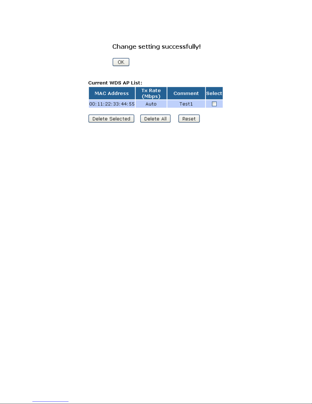
18. Click Apply Changes button.
19. Change setting successfully! Click on OK button to confirm and return.
20. The MAC Address that you created has been added in the Current Access Control List.

Wireless Access Point HNW300APN
User Manual 70
Configure AP (Access Point) + WDS (Wireless Distribution System)
1. From the left-hand Wireless menu, click on Basic Settings.
2. From the Mode drop-down list, select AP+WDS.
3. Enter SSID for example 11n_AP_Router.
4. From the Channel Number drop-down list, select a Channel.
5. Click Apply Changes button.
6. Change setting successfully! Click on OK button to confirm and return.

Wireless Access Point HNW300APN
User Manual 71
7. From the left-hand Wireless menu, click on WDS settings.
8. Check on the option Enable WDS.
9. Enter the MAC Address.
10. Enter the Comment.
11. Click the Set Security.
12. This page allows you setup the wireless security for WDS. When enabled, you must make sure each
WDS device has adopted the same encryption algorithm and Key.
13. Configure each field with the Encryption that you selected.
14. Click Apply Changes button.

Wireless Access Point HNW300APN
User Manual 72
15. Change setting successfully! Click on OK button to confirm and return.
16. Click Close button to close and exit the WDS Security Setup.
17. Click Apply Changes button.
Wireless Access Point HNW300APN
User Manual 73
18. Change setting successfully! Click on OK button to confirm and return.
19. The MAC Address that you created has been added in the Current Access Control List.
Wireless Access Point HNW300APN
User Manual 74
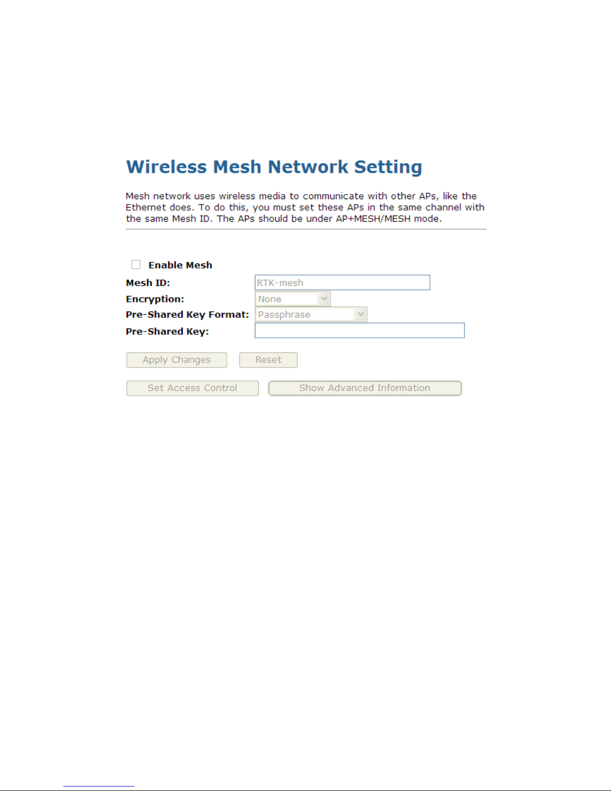
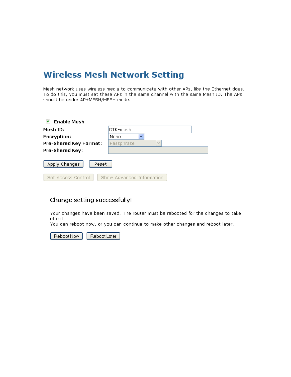
10.6 Mesh settings
Mesh network uses wireless media to communicate with other APs, like the Ethernet does. To do this, you
must set these APs in the same channel with the same Mesh ID. The APs should be under
AP+MESH/MESH mode. To access the Wireless Mesh Network Setting page:
From the left-hand Wireless menu, click on Mesh settings. The following page is displayed:
Wireless Access Point HNW300APN
User Manual 75
Configure Mesh settings only
1. From the left-hand Wireless menu, click on Basic Settings.
2. From the Mode drop-down list, select MESH.
3. From the Channel Number drop-down list, select a Channel.
4. Click Apply Changes button.
5. Change setting successfully! Click on Reboot Now button to confirm take effect.
6. From the left-hand Wireless menu, click on Mesh settings.

Wireless Access Point HNW300APN
User Manual 76
7. Check on the option Enable Mesh.
8. Enter the Mesh ID.
9. From the Encryption drop-down list, select the one and configure related settings.
10. Click the Apply Changes.
11. Change setting successfully! Click on Reboot Now button to confirm take effect.
Wireless Access Point HNW300APN
User Manual 77
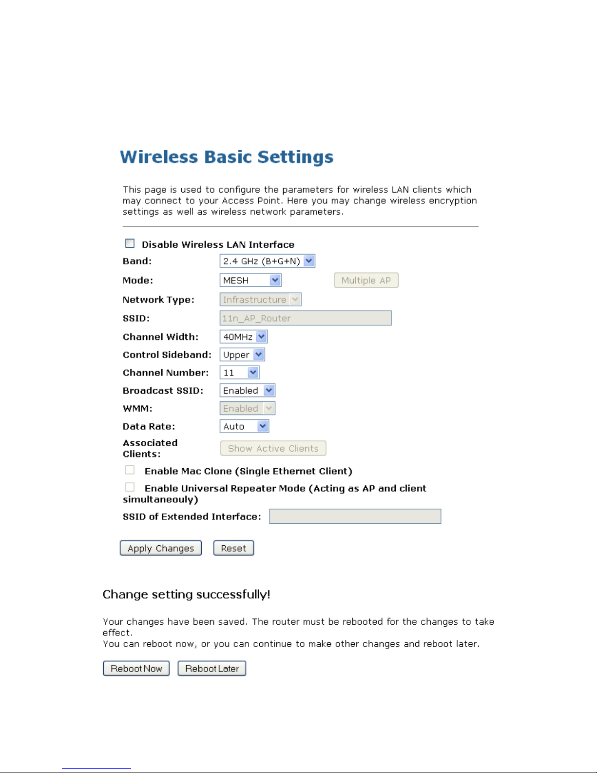
Configure AP (Access Point) + MESH
1. From the left-hand Wireless menu, click on Basic Settings.
2. From the Mode drop-down list, select AP+MESH.
3. Enter SSID for example 11n_AP_Router.
4. From the Channel Number drop-down list, select a Channel.
5. Click Apply Changes button.
6. Change setting successfully! Click on Reboot Now button to confirm take effect.
Wireless Access Point HNW300APN
User Manual 78
7. From the left-hand Wireless menu, click on Mesh settings.
8. Check on the option Enable Mesh.
9. Enter the Mesh ID.
10. From the Encryption drop-down list, select the one and configure related settings.
11. Click the Apply Changes.
12. Change setting successfully! Click on Reboot Now button to confirm take effect.
Wireless Access Point HNW300APN
User Manual 79
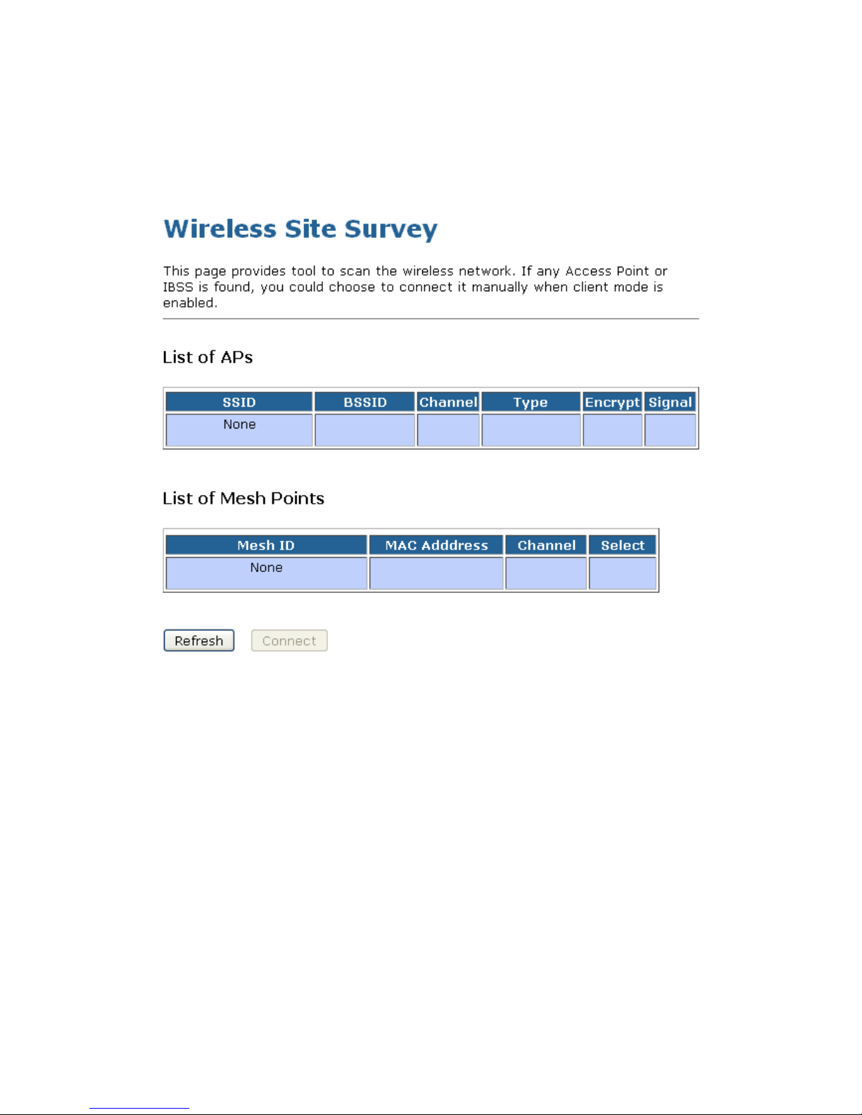
Site Survey
This page provides tool to scan the wireless network. If any Access Point or IBSS is found, you could
choose to connect it manually when client mode is enabled. To access the Wireless Network WDS settings
page:
From the left-hand Wireless menu, click on Site Survey. The following page is displayed:

Wireless Access Point HNW300APN
User Manual 80
Configure Wireless ISP + Wireless client + Site Survey
1. From the left-hand Operation Mode menu, click on Wireless ISP Settings.
2. Click Apply Changes button.
3. Change setting successfully! Click on OK button to confirm and return.
4. From the left-hand Wireless menu, click on Basic Settings.
5. From the Mode drop-down list, select Client.
6. Enter SSID of the AP that you want to connect to for example 11n_AP_Router. If you don’t know what
the SSID of the AP that you want to connect to, please skip this step.

Wireless Access Point HNW300APN
User Manual 81
7. Click Apply Changes button.
8. Change setting successfully! Click on OK button to confirm and return.
9. From the left-hand Wireless menu, click on Site Survey.

Wireless Access Point HNW300APN
User Manual 82
10. Click Refresh button.
11. Now you could see the APs that scanned by the Wireless Gateway were listed below.
12. Click on the ratio of AP’s SSID under the item Select that you want the Wireless Gateway to connect to.
13. Click Connect button.
14. Connect successfully! Click on OK button to confirm and return.

Wireless Access Point HNW300APN
User Manual 83
10.7 WPS
This page allows you to change the setting for WPS (Wi-Fi Protected Setup). Using this feature could let
your wireless client automatically syncronize its setting and connect to the Access Point in a minute without
any hassle. To access the Wireless Network WPS page:
From the left-hand Wireless menu, click on WPS. The following page is displayed:
Field Description
Disable WPS • Checking this box and clicking “Apply Changes” will disable
Wi-Fi Protected Setup. WPS is turned on by default.
WPS Status • When AP’s settings are factory default (out of box), it is set to
open security and un-configured state. It will be displayed by “WPS
Status”. If it already shows “Configured”, some registrars such as
Vista WCN will not configure AP. Users will need to go to the
“Save/Reload Settings” page and click “Reset” to reload factory
default settings.
Self-PIN Number • “Self-PIN Number” is AP’s PIN. Whenever users want to
change
AP’s PIN, they could click “Regenerate PIN” and then click “
Apply Changes”. Moreover, if users want to make their own PIN,
they could enter four digit PIN without checksum and then click “
Apply Changes”. However, this would not be recommended since
the registrar side needs to be supported with four digit PIN.

Wireless Access Point HNW300APN
User Manual 84
Field Description
Push Button
Configuration
Clicking this button will invoke the PBC method of WPS. It is only
used when AP acts as a registrar.
Apply Changes Whenever users want to enable/disable WPS or change AP’s PIN,
they need to apply this button to commit changes.
Reset It restores the original values of “Self-PIN Number” and “Client PIN
Number”.
Client PIN Number It is only used when users want their station to join AP’s network.
The length of PIN is limited to four or eight numeric digits. If users
enter eight digit PIN with checksum error, there will be a warning
message popping up.
If users insist on this PIN, AP will take it.
Introduction of WPS
Although home Wi-Fi networks have become more and more popular, users still have trouble with the initial
set up of network. This obstacle forces users to use the open security and increases the risk of
eavesdropping. Therefore, WPS is designed to ease set up of security-enabled Wi-Fi networks and
subsequently network management (Wi-Fi Protected Setup Specification 1.0h.pdf, p. 8).
The largest difference between WPS-enabled devices and legacy devices is that users do not need the
knowledge about SSID, channel and security settings, but they could still surf in a security-enabled Wi-Fi
network. For examples, in the initial network set up, if users want to use the PIN configuration, the only thing
they need to do is entering the device PIN into registrar, starting the PIN method on that device and simply
wait until the device joins the network. After the PIN method is started on both sides, a registration protocol
will be initiated between the registrar and the enrollee. Typically, a registrar could be an access point or
other device that is capable of managing the network. An enrollee could be an access point or a station that
will join the network. After the registration protocol has been done, the enrollee will receive SSID and
security settings from the registrar and then join the network. In other words; if a station attempts to join a
network managed by an access point with built-in internal registrar, users will need to enter station’s PIN
into the web page of that access point. If the device PIN is correct and valid and users start PIN on station,
the access point and the station will automatically exchange the encrypted information of the network
settings under the management of AP’s internal registrar. The station then uses this information to perform
authentication algorithm, join the secure network, and transmit data with the encryption algorithm. More
details will be demonstrated in the following sections.
Supported WPS features
Currently, Wireless Gateway supports WPS features for AP mode, AP+WDS mode, Infrastructure-Client
mode, and the wireless root interface of Universal Repeater mode.
Other modes such as WDS mode, Infrastructure-Adhoc mode, and the wireless virtual interface of
Universal Repeater mode are not implemented with WPS features.
If those unsupported modes are enforced by users, WPS will be disabled. Under the configuration of
every WPS-supported mode, Wireless Gateway has Push Button method and PIN method. For each
method, Wireless Gateway offers different security levels included in network credential, such as open
security, WEP 64 bits, WEP 128 bits, WPA-Personal TKIP, WPA-Personal AES, WPA2-Personal TKIP,
and WPA2-Personal AES. Users could choose either one of the methods at their convenience.

Wireless Access Point HNW300APN
User Manual 85
AP mode
For AP mode, Wireless Gateway supports three roles, registrar, proxy, and enrollee in registration protocol.
At different scenarios, Wireless Gateway will automatically switch to an appropriate role depending on the
other device’s role or a specific configuration.
AP as Enrollee
If users know AP’s PIN and enter it into external registrar, the external registrar will configure AP with a new
wireless profile such as new SSID and new security settings. The external registrar does this job either
utilizing the in-band EAP (wireless) or out-of-band UPnP (Ethernet). During the WPS handshake, a wireless
profile is encrypted and transmitted to AP. If the handshake is successfully done, AP will be re-initialized
with the new wireless profile and wait for legacy stations or WPS stations to join its network.
AP as Registrar
Wireless Gateway also has a built-in internal registrar. Whenever users enter station’s PIN into AP’s
webpage, click “Start PBC”, or push the physical button, AP will switch to registrar automatically. If users
apply the same method on station side and the WPS handshake is successfully done, SSID and security
settings will be transmitted to that station without the risk of eavesdropping. And then the station will
associate with AP in a security-enabled network.
AP as Proxy
At this state, AP is transparent to users. If users want to configure a station or any device that is capable of
being an enrollee, they have to enter device’s PIN into an external registrar and choose an appropriate
wireless profile. After the PIN is entered, the external registrar will inform AP this event. AP then conveys
the encrypted wireless profile between the device and the external registrar. Finally, the device will use the
wireless profile and associate with AP. However, the device may connect to other APs if the wireless profile
does not belong to the proxy AP. Users must carefully choose the wireless profile or create a wireless
profile on an external registrar.
Infrastructure-Client mode
In Infrastructure-Client mode, Wireless Gateway only supports enrollee’s role. If users click “Start PIN”, click
“Start PBC”, or press the physical button on Wireless Gateway, it will start to seek WPS AP. Once users
apply the same method on registrar side, Wireless Gateway will receive the wireless profile upon
successfully doing the registration protocol. Then Wireless Gateway will associate with an AP.
Instructions of AP’s and Client’s operations
At this state, AP is transparent to users. If users want to configure a station or any device that is capable of
being an enrollee, they have to enter device’s PIN into an external registrar and choose an appropriate
wireless profile. After the PIN is entered, the external registrar will inform AP this event. AP then conveys
the encrypted wireless profile between the device and the external registrar. Finally, the device will use the
wireless profile and associate with AP. However, the device may connect to other APs if the wireless profile
does not belong to the proxy AP. Users must carefully choose the wireless profile or create a wireless
profile on an external registrar.

Wireless Access Point HNW300APN
User Manual 86
Wireless Advanced Settings page
Users need to make sure the “Broadcast SSID” file is set to “Enabled”. Otherwise, it might prevent WPS
from working properly.

Wireless Access Point HNW300APN
User Manual 87
10.8 Operations of AP - AP being an enrollee
In this case, AP will be configured by any registrar either through in-band EAP or UPnP. Here, users do not
need to do any action on AP side. They just need AP’s device PIN and enter it into registrar. An example
from Vista WCN will be given.
1. From the left-hand Wireless -> WPS menu. The following page is displayed:
2. Make sure AP is in un-configured state.
3. Plug the Ethernet cable into AP’s LAN port and make sure the IP connection is valid with Vista.
4. Make sure WCN is enabled. Users may need to enable it at the first time. They could open the “Control
Panel”, click “Classic View“, open “Administrative Tools”, double click “Services”, a User Account
Control pop up and click “Continue“, edit properties of “Windows Connect Now”, choose the “Startup
type” with “Automatic” and click “Start”.

Wireless Access Point HNW300APN
User Manual 88
5. If the previous steps are done, open Windows Explorer. Go to the Network section.
6. Click on “Network discovery and file sharing are turned off. Network computers and devices are not
visible. Click to Change…“

Wireless Access Point HNW300APN
User Manual 89
7. Click on “Turn on network discovery and file sharing“
8. Click on “No, make the network that I am connected to a private network“

Wireless Access Point HNW300APN
User Manual 90
9. AP’s icon will show up. Double click on it.
10. Users could also Click “Add a wireless device” if the icon is not there. Click “next”.

Wireless Access Point HNW300APN
User Manual 91
11. Enter AP’s Self-PIN Number and click “”Next”.
12. Choose a name that people who connect to your network will recognize.

Wireless Access Point HNW300APN
User Manual 92
13. Enter the Passphrase and then click “Next”.
14. A User Account Control screen pops up, click Continue.
15. AP is successfully configured by WCN.

Wireless Access Point HNW300APN
User Manual 93
16. Finally, AP will become configured (see WPS Status). The authentication algorithm, encryption
algorithm, and key assigned by WCN will be displayed below “Current Key Info”.
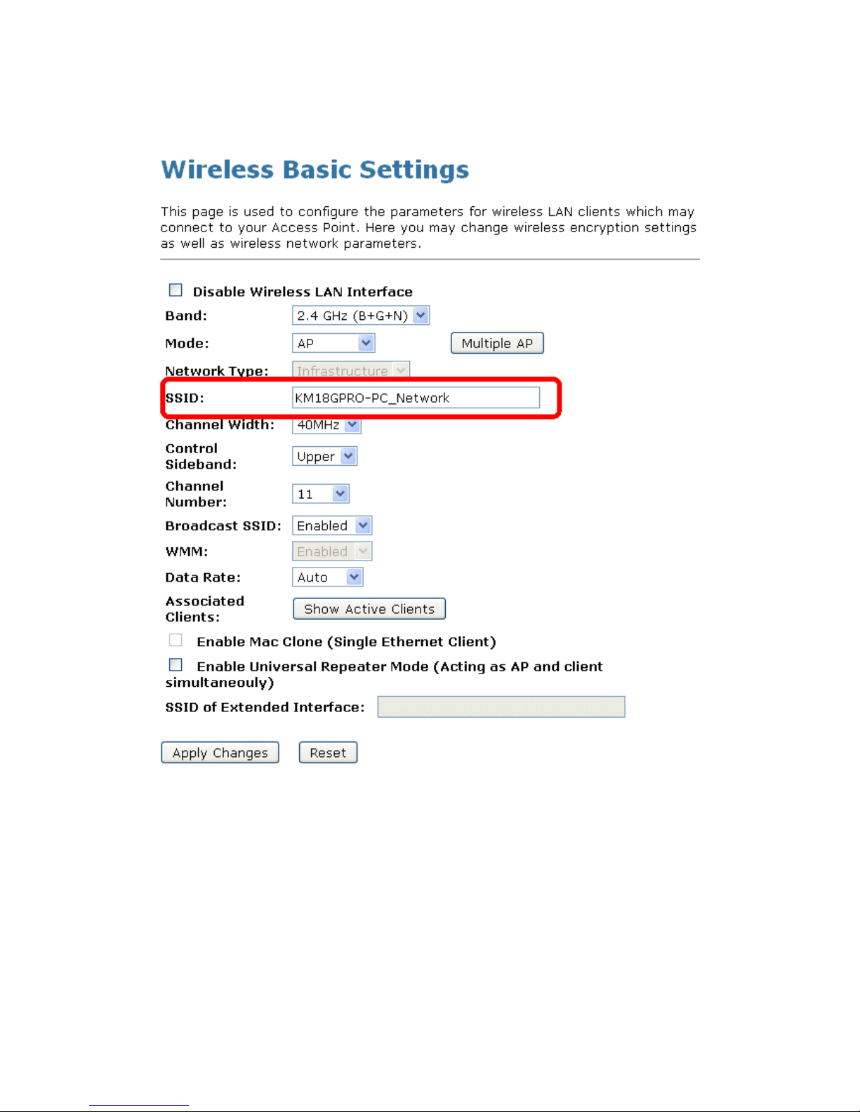
Wireless Access Point HNW300APN
User Manual 94
17. The SSID field of Wireless Basic Settings page will also be modified with the value assigned by WCN.
18. The security settings on the Wireless Security Page will be modified by WCN, too. The warning
message will show up if users try to modify the security settings. The reason is the same as we
explained in the previous section.
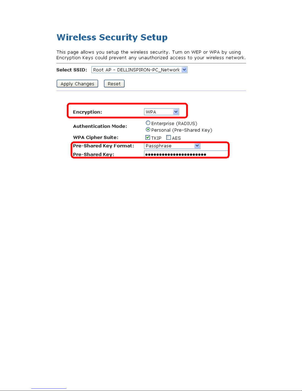
Wireless Access Point HNW300APN
User Manual 95

Wireless Access Point HNW300APN
User Manual 96
10.9 Operations of AP - AP being a registrar
AP mode
Whenever users enter station’s PIN into AP’s Wi-Fi Protected Setup page and click “Start PIN”, AP will
become a registrar. Users must start the PIN method on the station side within two minutes.
1. From the left-hand Wireless -> WPS menu. The following page is displayed:
2. Make sure AP is in un-configured state.
3. Enter the Client PIN Number.
4. Click Start PIN.
5. Users must start the PIN method on the station side within two minutes.
6. Users must start the PIN method on the station side within two minutes.

Wireless Access Point HNW300APN
User Manual 97
7. If the device PIN is correct and the WPS handshake is successfully done on the station side, User’s
Wi-Fi Protected status will be shown as below.
8. If the device PIN is correct and the WPS handshake is successfully done, AP’s Wi-Fi Protected Setup
page will be shown as below.
Other pages such as Wireless Basic Settings page and Wireless Security Setup page will also be
updated appropriately as described in previous sections. In this case, AP is in un-configured state
before the station initiates the WPS handshake. According to the WPS spec, AP will create a wireless
profile with WPA2-mixed mode and a random-generated key upon successfully doing the WPS
handshake. However, AP will use the original wireless profile and give it to the station if AP is already in
configured state. That means all settings of AP will not change. Hence, all WPS related pages keep the
same.

Wireless Access Point HNW300APN
User Manual 98
Push Button method
Wireless Gateway supports a virtual button “Start PBC” on the Wi-Fi Protected Setup page for Push Button
method. If users push a virtual button “Start PBC”, AP will initiate a WPS session and wait for any station to
join. At this moment, AP will detect whether there is more than one station that starts the PBC method.
When multiple PBC sessions occur, users should try PIN method.
After users push AP’s virtual button “Start PBC”, they must go to station side to push its button within two
minutes. If the WPS is successfully done, AP will give its wireless profile to that station. The station could
use this profile to associate with AP.
1. From the left-hand Wireless -> WPS menu. The following page is displayed:
2. Make sure AP is in un-configured state.
3. Click Start PBC.
4. Users must start the PBC method on the station side within two minutes.
5. Users must start the PBC method on the station side within two minutes.

Wireless Access Point HNW300APN
User Manual 99
6. If the device PBC and the WPS handshake are successfully done on the station side, User’s Wi-Fi
Protected status will be shown as below.
7. If the device PIN is correct and the WPS handshake is successfully done, AP’s Wi-Fi Protected Setup
page will be shown as below.
Other pages such as Wireless Basic Settings page and Wireless Security Setup page will also be
updated appropriately as described in previous sections. In this case, AP is in un-configured state
before the station initiates the WPS handshake. According to the WPS spec, AP will create a wireless
profile with WPA2-mixed mode and a random-generated key upon successfully doing the WPS
handshake. However, AP will use the original wireless profile and give it to the station if AP is already in
configured state. That means all settings of AP will not change. Hence, all WPS related pages keep the
same.
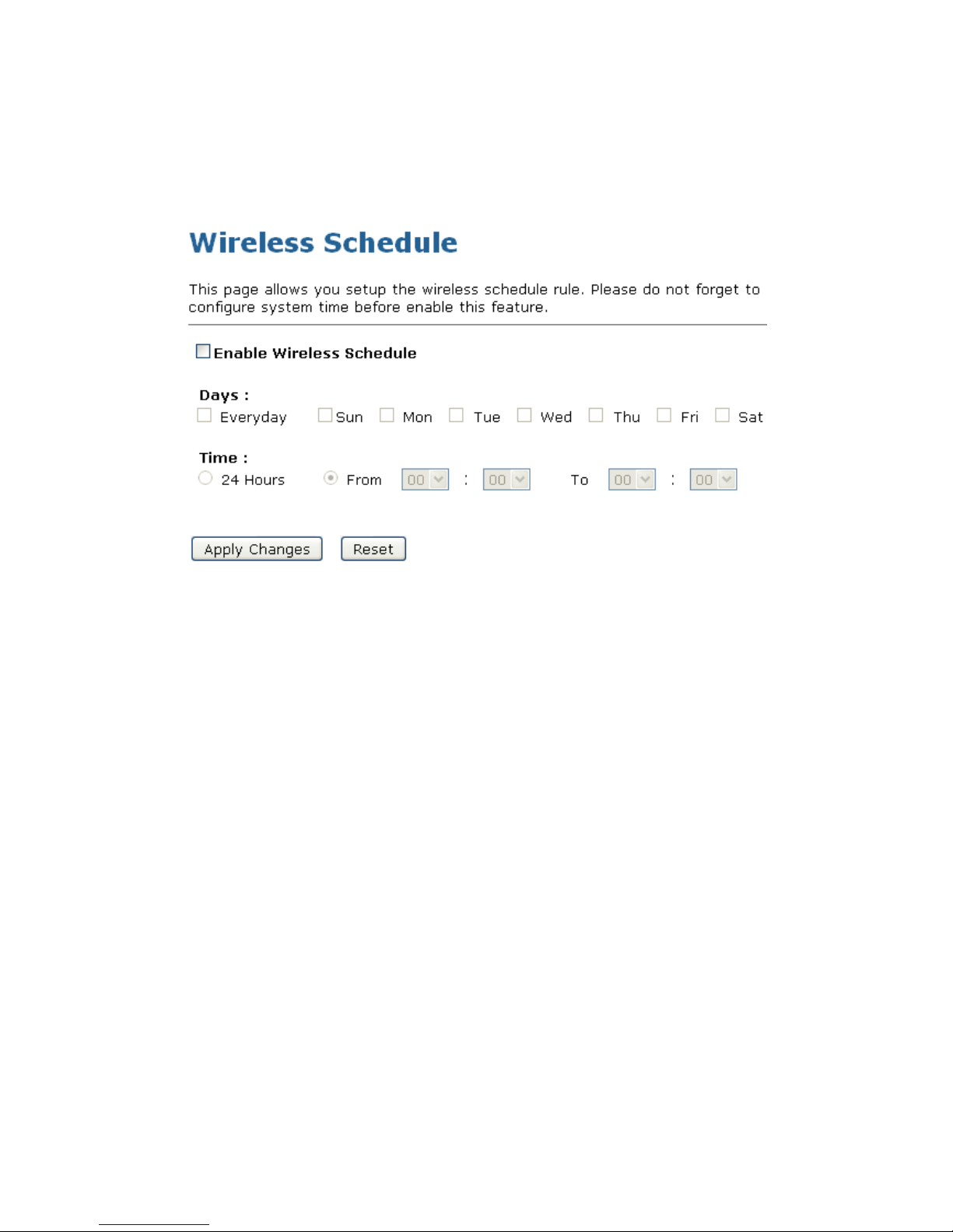
Wireless Access Point HNW300APN
User Manual 100
10.10 Wireless Schedule
This page allows you setup the wireless schedule rule. Please do not forget to configure system time before
enable this feature. To access the Wireless Schedule page:
From the left-hand Wireless menu, click on Wireless Schedule. The following page is displayed:
 Loading...