

Page 1

COMPACT ONE-PIECE
BALL VALVES
H-800 SERIES
VALVES & ACTUATORS
Page 2

H-800 FEATURES
Certified for ISO 15848-1:2006(E)
Encapsulated Ball Stem design
On/off-service, one-piece Ball Valve with 2-way pattern
Diverter and on/off–service, one-piece Ball Valve with 3-way pattern
Stainless Steel construction
Allows bi-directional flow in 2-way straight pattern
Has virtually no dead volume
One-piece Ball Stem ensures alignment of stem and orifice
MAWP 3000 psi (206 bar) ; MAWT 300ºF (149ºC)
Panel mountable
Vent options
Variable end connection types and sizes from 1/16” to 1/2”, 3mm to 12mm
Operation with colored Nylon handles, metal handle and pneumatically actuated
MATERIALS OF CONSTRUCTION
No. Components Qty Material
1 Handle 1 Nylon + Glass Fiber
2 Set Screw 1 St.St.304
3 Panel Nut 1 St.St.304
4 Packing Bolt 1 St.St.316
5 Gland 1 St.St.304
6 Stem Packing 1 Virgin PTFE
7 Washer 1 St.St.304
8 Ball Stem 1 St.St.316
9 Seat Disc 2 St.St.304 (PTFE coated)
10 Seat 1 PFA
11 Seat Ring 2 St.St.304 (PTFE coated)
12 Body 1
St.St. ASTM A351 Gr. CF8M
H-800 GENERAL
The H-800, one-piece Ball Valve series is designed for general
service and instrumentation panels. Valve design enables
low and high working pressure and accommodates a wide
temperature range with high life cycle.
One-piece body design reduces possibility of shell leakage.
The valves offer tight shutoff, long-life service and low
operating torque.
HAM-LET H-800 Ball Valves are designed for fully open or fully closed
operations only. After a period of non-operation, the valve’s braking
torque may rise.
1
2
3
4
VALVES & ACTUATORS
Directional Handle
indicates on/off
position
Nut for Panel
Mounting
Ball-Stem design enables
bi-directional flow
1/4 Turn Operation for
straight and angle pattern.
1/2 Turn Operation for
T type valve
Adjustable Packing
can repair seat &
packing leakages
Encapsulated Stem does not
require system pressure to
seal, reduces potential leakage
points and is easily cleaned
and purged
5
6
7
8
9
10
11
12
COMPACT ONE-PIECE BALL VALVES H-800 SERIES
202
Page 3
TESTING
S
G
The H-800 design has been tested for Burst and Proof. Standard testing
for each H-800 valve includes testing with nitrogen at 80 &1000 psig.
Each valve is tested for leakage through the shell, packing and ball seats.
The maximum allowable leakage across the ball seats is 0.1 std cc/min.
CLEANING & PACKAGING
Every H-800 series ball valve is cleaned in accordance with Standard
Cleaning and Packaging (procedure 8184). Oxygen Clean & Lubricant
Free Cleaning and packaging, in accordance with Special Cleaning and
Packaging (procedure 8185), is available as an option.
Lubricant free cleaned valves have significantly higher actuation torque.
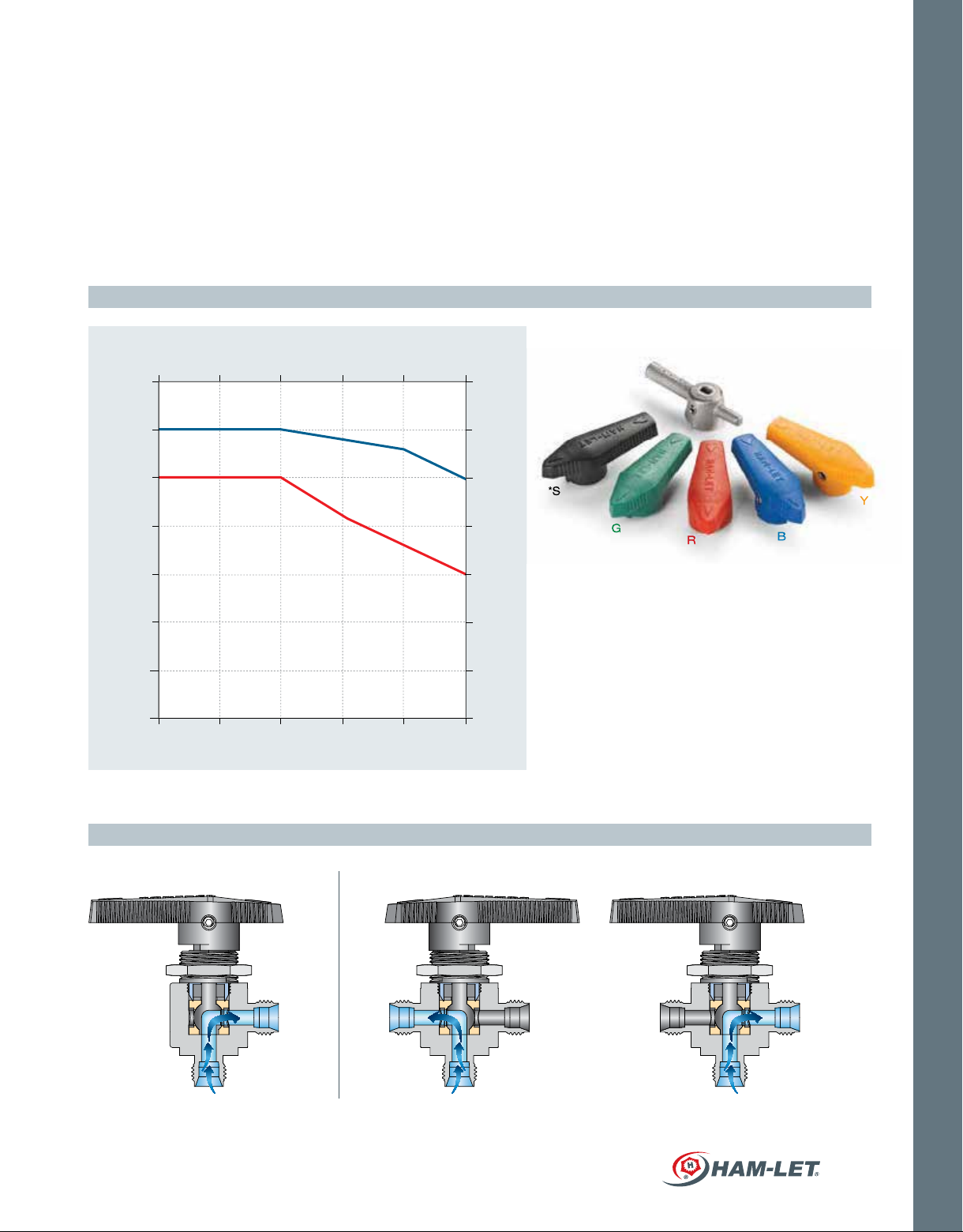
PRESSURE TEMPERATURE RATING
Temp. (°C)
-54 0 38 93 121 149
3500
PACKING ADJUSTMENT
Due to the varied service applications of the valve, packing adjustment
may occasionally be necessary.
Packing adjustment for this valve can fix not only leakage through
stem but also leakage through the seats.
Packing is factory adjusted to 1000 psig service. Initial adjustment is
recommended after installation and prior to start-up.
HAM-LET Ball Valves are designed for operation in fully closed or fully
open position only.
H-800 COLORED AND METAL HANDLES
250
3000
2500
2000
1500
Pressure (psig)
1000
For LF Services MAWP: Body size Large500psi
FLOW DIRECTION
H-800S, H-800M
H-800L
500
0
Temp. (°F)
Body size Small and Medium 1000psi
207
172
138
103
*S
MANUAL OPERATION
Pressure (bar)
Y
G
R
B
S - Black Handle*
69
B - Blue Handle
R - Red Handle
G - Green Handle
34
0
3002502001000-65
Y - Yellow Handle
M- Metal Handle
* Black Nylon handle is standard.
VALVES & ACTUATORS
H-800 T-Type H-800 Angle-Type
NOTE: Side entry is allowed and limted to 1500 psi for all sizes
HAM-LET ADVANCED CONTROL TECHNOLOGY
203
Page 4

VALVES & ACTUATORS
STRAIGHT PORT VALVE & ANGLE PATTERN
(Required
panel hole)
STANDARD CONFIGURATION DIMENSIONS
End
Connection
Type Size A B C
1/16
1/8
Let-Lok®
Imperial
1/4
3/8
1/2 L
3mm
6mm
Let-Lok®
Metric
8mm
10mm L
12mm L
1/8
F-NPT
1/4
3/8
M-NPT
M-NPT to
Let-Lok
Female
ISO 7-1
tapered
O-Ring
Face Seal
Face Seal
Male
®
1/4
1/4
1/4
3/8 L
1/4
1/4
1/2 L
Orifice CV
straightCVangle
Body Size
mm inch
Designator
mm inch mm inch mm inch mm inch mm inch mm inch mm inch mm inch mm inch mm inch mm inch
1.3 0.051 0.1 - 42.7 1.68 21.35 0.84 20.6 0.81
2.4 0.094 0.2
S
3.2 0.126 0.6
M
4.8 0.189
L
7.1 0.279
2.4 0.094 0.2
S
3.2 0.126 0.6
M
4.8 0.189
7.1 0.279
S
3.2 0.126 0.5
M
4.8 0.189
L
7.1 0.279
4.8 0.189
M
1.4
1.5
6
6
1.4
1.5
6
6
1.2
0.9
3
2.6
1.2
1.6
0.15
51.1 2.01 25.70 1.01 24.6 0.97
0.35
56.1 2.21 28.05 1.10 27.2 1.07
0.9
60.7 2.39 30.50 1.20 29.7 1.17
0.9
65.5 2.58 32.75 1.29 32.8 1.29
2
77.5 3.05 38.60 1.52 36.3 1.43
4.6
83.12 3.27 41.56 1.63 39.16 1.54
0.15
51.1 2.01 25.70 1.01 24.6 0.97
0.35
56.1 2.21 28.05 1.10 27.2 1.07
0.9
60.7 2.39 30.35 1.20 29.7 1.17
0.9
62.5 2.46 31.25 1.23 30.5 1.2
2
78.0 3.07 38.90 1.53 36.3 1.43 14.2 0.56 14.2 0.56 50.8 2 82.3 3.24 9.5 0.38 28.6 1.13
4.6
83.12 3.27 41.56 1.63 39.16 1.54
0.3
41.4 1.63 20.60 0.81 20.6 0.81 8.6 0.34 7.1 0.28 31.0 1.22 50 1.97 6.4 0.25 15.1 0.59
0.7
50.8 2.00 25.40 1.00 25.4 1.00 11.2 0.44 9.7 0.38 38.9 1.53 63 2.48 4.8 0.19 19.8 0.78
0.75
52.3 2.06 26.20 1.03 26.2 1.03 11.2 0.44 9.7 0.38 38.9 1.53 63 2.48 4.8 0.19 19.8 0.78 19.8 0.78
1.7
63.5 2.50 31.75 1.25 31.75 1.25 14.2 0.56 14.2 0.56 50.8 2 82.3 3.24 9.5 0.38 28.6 1.13
1.5
63.5 2.50 31.75 1.25 31.75 1.25 14.2 0.56 14.2 0.56 50.8 2 82.3 3.24 9.5 0.38 28.6 1.13
0.75
50.8 2.00 25.40 1.00 26.2
0.75
55.9 2.20 30.5 1.20 26.2
0.9 - 52.3 2.06 26.15 1.03 26.15
7.1 0.279 2.6
S
3.2 0.126 0.6
M
4.8 0.189 2.4
S
3.2 0.126 0.6
M
4.8 0.189 2.4
7.1 0.279 6
-
63.5 2.50 31.75 1.25 31.75 1.25 14.2 0.56 14.2 0.56 50.8 2 82.3 3.24 9.5 0.38 28.6 1.13 52.6 2.07 28.4 1.12
0.35
44.4 1.75 22.40 0.88
0.9
47.8 1.88 23.90 0.94
0.35
54.1 2.13 27.05 1.06 27.7 1.09
0.9
-
73.2 2.88 36.60 1.44
(Angle)
23.9 0.94
--
(Required
panel hole)
DIMENSIONS
D E F LG
(Diameter)
H
JW
8.6 0.34 7.1 0.28 31.0 1.22 50 1.97 6.4 0.25 15.1 0.59 34.5 1.36 17 0.67
11.2 0.44 9.7 0.38 38.9 1.53 63 2.48 4.8 0.19 19.8 0.78
14.2 0.56 14.2 0.56 50.8 2 82.3 3.24 9.5 0.38 28.6 1.13
14.2 0.56 14.2 0.56 50.8 2 82.3 3.24 9.5 0.38 28.6 1.13
8.6 0.34 7.1 0.28 31.0 1.22 50 1.97 6.4 0.25 15.1 0.59
11.2 0.44 9.7 0.38 38.9 1.53 63 2.48 4.8 0.19 19.8 0.78
37.3 1.47
52.6 2.07
52.6 2.07
34.5 1.36
37.3 1.47
52.6 2.07
14.2 0.56 14.2 0.56 50.8 2 82.3 3.24 9.5 0.38 28.6 1.13
52.6 2.07
34.5 1.36
37.3 1.47
52.6 2.07
52.6 2.07
1.03 11.2 0.44 9.7 0.38 38.9 1.53 63 2.48 4.8 0.19 19.8 0.78
11.2 0.44
11.2 0.44
11.2 0.44 31.0 1.22 50 1.97 3.2 0.13 15.1 0.59
9.7 0.38
11.2 0.44
31.0 1.22 50 1.97 3.2 0.13 15.1 0.59
38.9 1.53 63 2.48 4.8 0.19 19.8 0.78
38.9 1.53 63 2.48 4.8 0.19 19.8 0.78
14.2 0.56 14.2 0.56 50.8 2 82.3 3.24 9.5 0.38 28.6 1.13
37.3 1.47
34.5 1.36
37.3 1.47
34.5 1.36
37.3 1.47
52.6 2.07
19.8 0.78
28.4 1.12
28.4 1.12
17 0.67
19.8 0.78
28.4 1.12
28.4 1.12
17 0.67
19.8 0.78
28.4 1.12
28.4 1.12
19.8 0.78
19.8 0.78
19.8 0.78
19.8 0.78
19.8 0.78
38.1 1.5
Dimensions are for reference only, and are subject to change.
COMPACT ONE-PIECE BALL VALVES H-800 SERIES
204
Page 5

3-WAY VALVE
(Required
panel hole)
STANDARD CONFIGURATION DIMENSIONS
End
Connection
Type Size A B C D F L G
1/16
1/8
Let-Lok®
Imperial
1/4
3/8 M 65.5 2.58 32.75
1/2 L 4.6
3mm
6mm
Let-Lok®
Metric
8mm 0.8
10mm L
12mm L 4.6
1/8 S
1/4
F-NPT
3/8 1.5
M-NPT to
Let-Lok
Female
ISO 7-1
tapered
Face Seal
Male
1/4
1/4
3/8 L
1/4
Orifice CV
Body Size
mm inch
Designator
1.3 0.051
2.4 0.094
S
3.2 0.126
M
4.8 0.189
L
7.1 0.279
2.4 0.094
S
3.2 0.126
M
4.8 0.189
7.1 0.279
3.2 0.126
M
4.8 0.189
L
7.1 0.279
4.8 0.189
M
7.1 0.279
S
3.2 0.126
M
4.8 0.189
DIMENSIONS
mm inch mm inch mm inch mm inch mm inch mm inch mm inch mm inch mm inch mm inch
0.08
42.7 1.68 21.35 0.84 20.6 0.81
0.15
51.1 2.01 25.70 1.01 24.6 0.97
0.35
56.1 2.21 28.05 1.10 27.2 1.07
60.7 2.39 30.50 1.20 29.7 1.17
0.9
2
73.4 2.89 36.80 1.45 36.3 1.43
1.29 33.0 1.3
79.0 3.11 39.5 1.55 39.1 1.54
0.15
51.1 2.01 25.70 1.01 24.6 0.97
0.35
56.1 2.21 27.90 1.10 27.2 1.07
0.9
60.7 2.39 30.50 1.20 29.7 1.17
62.5 2.46 31.25 1.23 30.5 1.2
2
73.4 2.89 36.80 1.45 36.3 1.43 14.2 0.56 50.8 2 82.3 3.24 9.5 0.38 28.6 1.13
79.0 3.11 39.5 1.55 39.1 1.54
0.3
41.4 1.63 20.60 0.81 20.6 0.81 8.6 0.34 31.0 1.22 50 1.97 6.4 0.25 15.1 0.59
0.75
52.3 2.06 26.20 1.03 26.2 1.03 11.2 0.44 38.9 1.53 63 2.48 4.8 0.19 19.8 0.78
1.7
63.5 2.50 31.75 1.25 31.75 1.25 14.2 0.56 50.8 2 82.3 3.24 9.5 0.38 28.6 1.13
8.6 0.34 31.0 1.22 50 1.97 6.4 0.25 15.1 0.59 34.5 1.36 17 0.67
11.2 0.44
38.9 1.53
63 2.48 4.8 0.19 19.8 0.78
14.2 0.56 50.8 2 82.3 3.24 9.5 0.38 28.6 1.13
14.2 0.56 50.8 2.0 82.3 3.24 9.5 0.38 28.6 1.13
8.6 0.34 31.0 1.22 50 1.97 6.4 0.25 15.1 0.59
11.2 0.44 38.9 1.53 63 2.48 4.8 0.19 19.8 0.78
14.2 0.56 50.8 2.0 82.3 3.24 9.5 0.38 28.6 1.13
63.5 2.50 31.75 1.25 31.75 1.25 14.2 0.56 50.8 2 82.3 3.24 9.5 0.38 28.6 1.13
0.8
60.7 2.39 30.50 1.20 26.2
0.75
52.3 2.06 26.15 1.03 26.15
1.5
63.5 2.50 31.75 1.25 31.75 1.25 14.2 0.56 50.8 2 82.3 3.24 9.5 0.38 28.6 1.13 52.6 2.07 28.4 1.12
0.35
54.1 2.13 27.05 1.06 27.7 1.09
0.9
1.03 11.2 0.44 38.9 1.53 63 2.48 4.8 0.19 19.8 0.78
11.2 0.44 31.0 1.22 50 1.97 3.2 0.13 15.1 0.59
11.2 0.44
38.9 1.53 63 2.48 4.8 0.19 19.8 0.78
H
(Diameter)
J W
37.3 1.47
52.6 2.07
52.6 2.07
34.5 1.36
37.3 1.47
52.6 2.07
52.6 2.07
34.5 1.36
37.3 1.47
52.6 2.07
52.6 2.07
37.3 1.47
34.5 1.36
37.3 1.47
19.8 0.78
28.4 1.12
28.4 1.12
17 0.67
19.8 0.78
28.4 1.12
28.4 1.12
17 0.67
19.8 0.78
28.4 1.12
28.4 1.12
19.8 0.78
19.8 0.78
19.8 0.78
VALVES & ACTUATORS
Dimensions are for reference only, and are subject to change.
HAM-LET ADVANCED CONTROL TECHNOLOGY
205
Page 6

H-800 - PNEUMATIC ACTUATED VALVES
FEATURES
90° Actuation for 2-way valves (Straight & Angle)
180° Actuation for T-type valves
Actuators comply with industry standards for interface with
ISO 5211, NAMUR and VDI/VDE 3845
Actuated valves are available factory assembled or separately, actuator
and mounting kits
Limit switches, proximity sensors, position indicators, solenoid valves, and
other accessories are available upon request
Standard Temperature range: -32°C to 90°C (-25.6°F to 194°F)
Optional: High Temperature, Low Temperature
MATERIAL OF CONSTRUCTION
No. Part Qty Material
1
Actuator 1 AL 356-T5
2
Coupling 1 St.St.316
3
Bracket 1 St.St.304
4
Washer Flat 4 St.St.304
5
Washer Spring 4 St.St.304
6
Screw 4 St.St.304
7
Panel Nut 2
8
H-800 1 St.St.316
90° Actuator on 2-way valve
St.St.316
GENERAL
Four standard actuator sizes are available upon request:
Mini (designator “A1”), Small (designator “A2”), Medium
(designator “A3”), Large (designator “A4”) and 180° actuator (designator “A2T”).
Improved operational speed enables better valve opening and closing control.
ATEX certification of Valves-Actuators assemblies are available on request at
the time of order quotation.
180° Actuator on T-type valve
VALVES & ACTUATORS
2
3
2
4
5
3
6
7
4
5
6
8
7
8
COMPACT ONE-PIECE BALL VALVES H-800 SERIES
206
Page 7

ACTUATED H-800 SERIES
The selection of Valve-Actuator assemblies provided herein is based on:
Valve maximum allowable working pressure
Ambient temperature (50 to 100°F / 10 to 37°C)
Actuator fits to valve based on operating pressure of 6 bar, as per table A.
To order H-800 ball valve factory assembled with an actuator, the actuator designator
shall be added to the valve part number / description per the below table.
Example:
H-800S-SS-L-1/4 with standard Spring Return Aluminum Actuator Normally Closed
H-800S-SS-L-1/4-A1C
To order an actuator and mounting bracket kit for field assembly: Spring Return
Actuator ordering number: Z-A1S Corresponding mounting bracket kit:
Z-800S-MK-F03-F04-A1
Lubricant free Valves:
For spring return actuator - select one size bigger then offered in the table below.
Example: If the offered actuator in the table is A2C, select A3C
For double acting actuator - Please contact your local representative
Table A: Ordering information for Actuated Valves
Series Ends Size Seats Minimum
S
H-800
H-800
T-Type
M
L
S
M
L
PFA 5 (72.5)
PFA 5 (72.5) A2TS A2TS A2T Z-A2TS Z-A2T
Actuator
Operating
Pressure
Bar (Psi)
Actuator Designators
(Factory Assembled)
Spring Return
NO NC
A1O A1C
A1O A1C Z-A1S Z-800M-MK-F03-F04-A1
A2O A2C Z-A2S
Note: For dimensions of Actuators assembled on the H-800
series, please refer to the HPA section.
HAM-LET ADVANCED CONTROL TECHNOLOGY
Double
Acting
A1
Actuator Ordering
Code
Spring
Return
Z-A1S
Double
Acting
Z-A1
Mounting Kit
Ordering info
VALVES & ACTUATORS
Z-800S-MK-F03-F04-A1
SR: Z-800L-MK-F03-F04-A2
DA: Z-800L-MK-F03-F04-A1
Z-800S-MK-F03-F04-A2
Z-800M-MK-F03-F04-A2
Z-800L-MK-F03-F04-A2
207
Page 8

H-800 SERIES ORDERING INFORMATION
OPTIONAL
VALVES & ACTUATORS
H-8 00 -S
Valve Series
Valve Type
00 - LET-LOK® Ends
10 - Female Ends
80 - Male Ends
85 - Male to Female
Ends
Body
Designator
S - Small
M - Medium
L - Large
SS
End Connection
Type
L -LET-LOK®
N - NPT
G - ISO parallel
R -ISO Tapered
GL -Metal Face seal
HL - One Lok
Body and Ends
Meterial
SS - St.St.316
L
--
1/4
End
Connection
Size
1/8 3 MM
1/4 6 MM
3/8 8 MM
1/2 10 MM
3/4 12 MM
Valve Pattern
Type
BLANK - Straight
A - Angle
T - 3-Port
For Actuated Valves
If special cleaning is required, LF / OC will be added in the end,
and be applicable for the Valve only.
Example: H - 800S - SS - L- 1/4 - A1 - OC
For ordering information of actuators for high tempuratures, please
refer to HAM-LET Pneumatic Actuator Catalog
For double mounting actuators, please contact your local representative
Actuators Accessories (Limit Switch, Solenoid Valve
please refer to HAM-LET Pneumatic Actuator Catalog
For Stainless Steel Actuators or Electric Actuators please contact your
local representative
T
-- - --
Vent Option
DV - Down Stream Vent*
* MAWP = 500 psi
Handle
BLANK
RH
BH
YH
GH
M
* Black Nylon handle is standard.
Black Nylon Handle*
Red Nylon Handle
Blue Nylon Handle
Yellow Nylon Handle
Green Nylon Handle
Metal (St.St.) Handle
Actuator Type
Select Per
Table A
*See Notes below
Treatment
BLANK - Standard Cleaning &
OC - Oxygen Clean
LF - Lubricant Free
Aluminum
Actuator*
Passivation
HANDLE KIT
Handle kit contains handle and set screw
Z-800 HK-S
H-800 Valve
Series
H-800, Rev.07, January 2015
COMPACT ONE-PIECE BALL VALVES H-800 SERIES
208
Body
Designator
S Small
M Medium
L Large
Handle Kit
-
Handle Type
S Black Nylon Handle
R Red Nylon Handle
B Blue Nylon Handle
Y Yellow Nylon Handle
G Green Nylon Handle
M Metal (St.St.) Handle
* Black Nylon handle is standard.
S
Warning!
The system designer and user have the sole responsibility
for selecting products suitable for their special
application requirements, ensuring their safe and
trouble-free installation, operation, and maintenance.
Application details, material compatibility and product
ratings should all be considered for each selected
product. Improper selection, installation or use of
products can cause property damage or personal injury.
 Loading...