

Page 1
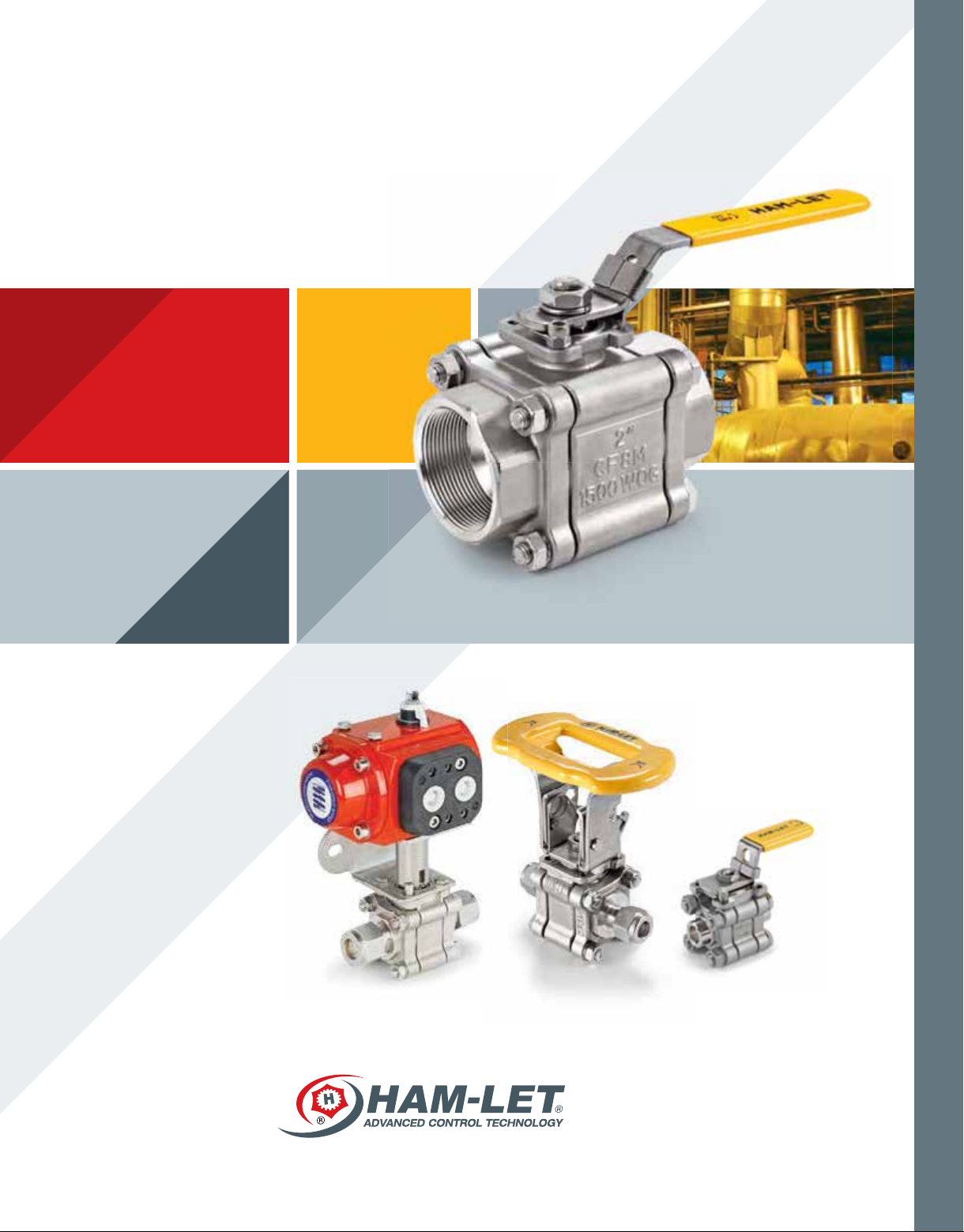
THREE-PIECE BALL VALVES
H-500 SERIES
VALVES & ACTUATORS
Page 2
H-500 FEATURES
3-piece heavy-duty ball valves with:
Certied for ISO 15848-1:2006(E)
Precision Investment cast body in CF8M stainless steel
Precision Investment cast end caps in CF3M stainless steel
Blow-out proof stem with Belleville washer design for long life stem sealing
Manual Operation with integral locking device
Flow coefcient (Cv) from 1.2 to 24.0
MAWP 3000 psig (206 Barg), 2000 psig (137 Barg) for “-FP” option
MAWT 450°F (232°C)
H-500S seat material is Modied PTFE as standard
GENERAL
The H-500 Series is a moderate-pressure instrumentation
Ball Valve for general service and instrumentation panels.
The valves offer large ports for high ow, tight shutoff, long-life
service and low operating torque.
The H-500 Series can be used for bi-directional ow, is rated to
max. 3000 psig (204 Bar) and performs as on/off service.
1
VALVES & ACTUATORS
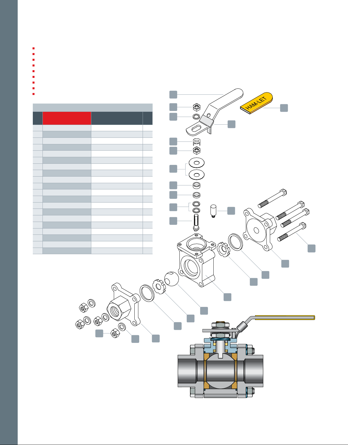
MATERIALS OF CONSTRUCTION
No. Components Material Qty
1 Handle St.St. 304
2 Stem Nut St.St. 304
3 Stem Washer St.St. 316
4 Lock Saddle St.St. 304
5 Belleville Washer
6 Gland St.St. 304
7 Stem Packing MG1241 / PTFE
8 Stem Seal MG1241
9 Stem St.St. 316
10 Locking Device St.St. 316
11 Handle Sleeve Vinyl
12 Stop Pin St.St. 304
13 Tightening Bolt
14 End Cap ASTM A351 Gr. CF3M
15 Joint Gasket PTFE
16 Seat PTFE
17 Body ASTM A351 Gr. CF8M
18 Ball St.St. 316
19 Washer St.St. 316
20 Bolt Nut St.St. 316
St.St. 304
St.St. 304
1
2
1
1
2
1
1
2
1
1
1
1
4
2
2
2
1
1
4
4
Note: If seat material other than PTFE is selected, Joint Gasket
and Stem Packing are changed accordingly.
2
11
3
10
4
2
5
6
7
8
12
9
12
13
14
15
16
17
20
19
THREE-PIECE BALL VALVES H-500 SERIES
210
18
16
15
14
Page 3
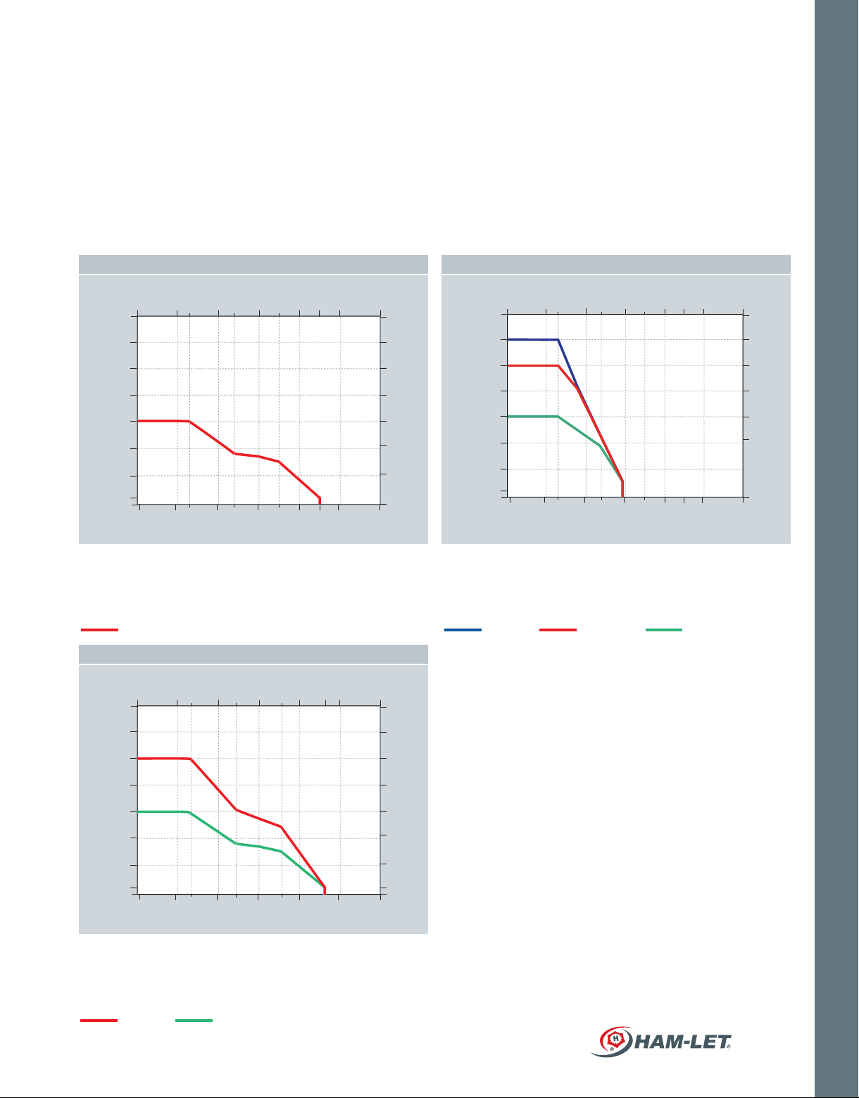
PRESSURE TEMPERATURE RATING
VIRGIN PTFE SEAT UHMWPE SEAT
Temp (°C) Temp (°C)
3500
3000
2500
2000
1500
Inlet Pressure (Psig)
1000
500
100
-28
0
-19
7222 122 172 186 222
93
148
298
98
37
199
160 250 340 43036770
240
207
172
137
103
70
35
6.9
Temp (°F) Temp (°F)
PTFE (Virgin PTFE) Color - White
PTFE is a good all around, general-purpose seat material. PTFE has
outstanding resistance to chemical attacks by a broad range of organic
chemicals, inorganic chemicals and solvents, and is generally considered
chemically inert. PTFE is a self lubricating polymer with a very low coefcient
of friction, which makes an excellent seat material
For all sizes
MODIFIED PTFE SEATS
Temp (°C)
-28
3500
3000
37
72 122 172 22220422
93
148
240
207
Inlet Pressure (bar)
UHMWPE Ultra-high-molecular-weight polyethylene
UHMWPE is a very tough material, highly resistant to corrosive chemicals
and suitable for low-radiation service. UHMWPE is self-lubricating, highly
resistant to abrasion, has an extremely low moisture absorption and a very
low coefcient of friction. UHMWPE meets the requirements for the tobacco
industry.
Inlet Pressure (Psig)
3500
3000
2500
2000
1500
1000
500
100
0
Up to 1/2”
-28
-19
7222 122 172 186 222
93
37
199
98
160 250 340 43036770
148
298
3/4” to 1” 1-1/4” to 2”
240
207
172
137
103
70
35
6.9
Inlet Pressure (bar)
VALVES & ACTUATORS
2500
2000
1500
1000
Inlet Pressure (Psig)
500
100 6.9
0
-19
98
199
160 250 340 43040070
298
172
137
103
70
35
Temp (°F)
MODIFIED PTFE - (PFA and PTFE composite) Color - Bright White
MODIFIED PTFE is an excellent seat material for purity applications and has
very low residual material during operation. It has a lower deformation ratio
than PTFE, but a higher pressure and temperature rating than PTFE. Chemical
resistance is equal to PTFE material.
1/4” to 1”
1-1/4” to 2”
HAM-LET ADVANCED CONTROL TECHNOLOGY
Inlet Pressure (bar)
211
Page 4
PACKING ADJUSTMENT
Due to the varied service applications of the
valve, packing adjustment may occasionally
be necessary. Packing is factory adjusted to
1000 psig service. Initial packing adjustment
is recommended after installation and prior
to start-up. Please nd more information on
H-500 under Installation Instructions.
HAM-LET Ball Valves are designed for
operation in the fully closed or fully open
position.
TESTING
The H-500 design has been tested for Burst
and Proof. Standard testing for each H-500
valve includes testing with nitrogen at 80
&1000 psig. Each valve is tested for leakage
through the shell, packing and ball seats. The
maximum allowable leakage across the ball
seats is 0.1 std cc/min.
CLEANING & PACKAGING
Every H-500 series ball valve is cleaned in
accordance with Standard Cleaning and
Packaging (procedure 8184). Oxygen Clean
& Lubricant Free Cleaning and packaging,
in accordance with Special Cleaning and
Packaging (procedure 8185), is available as an
option.
Lubricant free cleaned valves have
signicantly higher actuation torque.
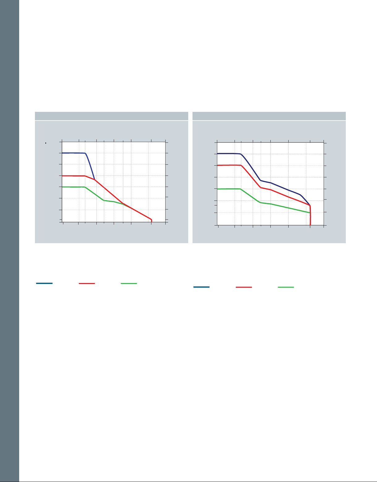
ST. ST. POWDER 50% FILLED PTFE SEATS
Temp (°C)
3500
3000
2500
2000
1500
1000
Inlet Pressure (Psig)
500
100
-28
0
-19
72 122 172 23222
93
3737
199
98
160 250 340 45070
148
298
240
207
172
137
103
70
35
6.9
Temp (°F)
St. St. Powder Filled PTFE Color - Gray
Excellent seat material for general applications to prevent over
expansion and seat extrusion.
It has a lower deformation ratio than PTFE, but a higher pressure and
temperature rating. Chemical resistance is equal to PTFE material.
3/4” to 1”Up to 1/2”
1-1/4” to 2”
PEEK SEATS
Temp (°C)
Inlet Pressure (bar)
3500
3000
2500
2000
1500
1000
Inlet Pressure (Psig)
800
500
-28
0
-19
98
3737
72 122 172 23222
93
199
160 250 340 45070
Temp (°F)
PEEK (Poly Ether Ether Keton) Color - Offwhite
Excellent seat material for high-pressure and high-temperature
applications. Excellent chemical resistance.
Can be used countinuously to 450°F (232°C) and in hot water or steam
without permanent loss in physical properties.
High strength for hostile environment and high pressure.
3/4” to 1”Up to 1/2” 1-1/4” to 2”
240
207
172
137
103
70
35
6.9
Inlet Pressure (bar)
VALVES & ACTUATORS
THREE-PIECE BALL VALVES H-500 SERIES
212
Page 5

H-500 LET-LOK® STANDARD CONFIGURATION DIMENSIONS
SERIES
H-500S
H-500
End Connection
mm inch mm inch mm inch mm inch mm inch mm inch mm inch mm inch mm inch mm inch mm inch
6
10
12 1/2” 10.3 0.40 7.6 11.0 0.43 92.3 3.63 20.6 0.81 44.4 1.75 40.5 1.59 56.5 2.22 22.2 0.87 121.5 4.78
20 3/4” 13.0 0.51 13.6 14.1 0.56 92.7 3.65 24.6 0.97 50.8 2.00 44.0 1.73 60.0 2.36 28.6 1.13 121.5 4.78 38.2 1.50
25 1” 20.0 0.79 36.0 20.0 0.79 124.4 4.90 31.8 1.25 60.0 2.36 56.7 2.23 74.5 2.93 38.1 1.50 151 5.94 44.0 1.73
Orice Cv Ball ID A B F C D H J G
4.8 0.19 1.2 4.8 0.19 80.5 3.17 15.1 0.59 38.5 1.52 33.2 1.31 48.0 1.89 14.3 0.56 61.0 2.40
1/4’’
7.1 0.28 3.7 7.1 0.28 80.5 3.17 15.1 0.59 38.5 1.52 33.2 1.31 48.0 1.89 17.5 0.69 61.0 2.40
3/8”
25.5 1.00
25.5 1.00
32.0 1.26
H-510 FEMALE NPT / BSPT STANDARD CONFIGURATION DIMENSIONS
SERIES
H-510S
H-510
Dimensions are for reference only, and are subject to change without notice.
End
Connection
1/4’’
3/8”
1/2” 11.0 0.43 10 11.0 0.43 70.0 2.76 20.6 0.81 44.4 1.75 40.5 1.59 56.5 2.22 27.0 1.06 121.5 4.78
3/4” 14.1 0.56 12.0 14.1 0.56 74.0 2.91 24.6 0.97 50.8 2.00 44.0 1.73 60.0 2.36 33.0 1.30 121.5 4.78 38.2 1.50
1” 20.0 0.79 36.0 20.0 0.79 99.0 3.90 31.8 1.25 60.0 2.36 56.7 2.23 74.5 2.93 42.0 1.65 151 5.94 44.0 1.73
Orice Cv Ball ID A B F C D H J G
mm inch mm inch mm inch mm inch mm inch mm inch mm inch mm inch mm inch mm inch
7.1 0.28 1.2 7.1 0.28 54.9 2.16 15.1 0.59 38.5 1.52 33.2 1.31 48.0 1.89 19.0 0.75 61.0 2.40
11.0 0.43 10 11.0 0.43 70.0 2.76 20.6 0.81 44.4 1.75 40.5 1.59 56.5 2.22 27.0 1.06 121.5 4.78 32.0 1.26
HAM-LET ADVANCED CONTROL TECHNOLOGY
VALVES & ACTUATORS
25.5 1.00
32.0 1.26
213
Page 6

ID
M
H-510 TUBE SOCKET WELD STANDARD CONFIGURATION DIMENSIONS
SERIES
H-510S
H-510
End
Connection
mm inch mm inch mm inch mm inch mm inch mm inch mm inch mm inch mm inch mm inch mm inch mm inch mm inch
10
12 1/2”
20 3/4”
25 1”
Orice Cv Ball ID A B F C D OD J G ID M
4.8 0.19 1.2 4.8 0.19 54.9 2.16 15.1 0.59 38.5 1.52 33.2 1.31 48.0 1.89 19.0 0.75 61.0 2.40
6
1/4’’
7.1 0.28 3.7 7.1 0.28 54.9 2.16 15.1 0.59 38.5 1.52 33.2 1.31 48.0 1.89 19.0 0.75 61.0 2.40
3/8”
10.3 0.40 7.5 11.0 0.43 70.0 2.76 20.6 0.81 44.4 1.75 40.5 1.59 56.5 2.22 20.5 0.81 121.5 4.78
14.1 0.56 12.0 14.1 0.56 74.0 2.91 24.6 0.97 50.8 2.00 44.0 1.73 60.0 2.362 27.0 1.06 121.5 4.78 38.2 1.50 19.2 0.76 14.2 0.56
22.35 0.88 38.0 22.35 0.88 99.0 3.90 31.8 1.25 60.0 2.36 56.7 2.23 74.5 2.93 34.0 1.34 151.0 5.94 44.0 1.73 25.55 1.08 19.2 0.76
25.5 1.00 4.80 0.19 7.10 0.28
25.5 1.00 7.10 0.28 7.90 0.31
32.0 1.26 12.85 0.51 12.7 0.50
VALVES & ACTUATORS
H-510 PIPE SOCKET WELD STANDARD CONFIGURATION DIMENSIONS
SERIES
H-510
Dimensions are for reference only, and are subject to change without notice.
214
End
Connection
1/4’’
3/8”
1/2”
3/4”
Orice Cv Ball ID A B F C D H J G ID M
mm inch mm inch mm inch mm inch mm inch mm inch mm inch mm inch mm inch mm inch mm inch mm inch
11.0 0.43 10 11.0 0.43 70.0 2.76 20.6 0.81 44.4 1.75 40.5 1.59 56.5 2.22 27.0 1.06 121.5 4.78
11.0 0.43 10 11.0 0.43 70.0 2.76 20.6 0.81 44.4 1.75 40.5 1.59 56.5 2.22 27.0 1.06 121.5 4.78 32.0 1.26 17.5 0.69 11.0 0.43
11.0 0.43 10 11.0 0.43 70.0 2.76 20.6 0.81 44.4 1.75 40.5 1.59 56.5 2.22 27.0 1.06 121.5 4.78
14.1 0.56 12.0 14.1 0.56 74.0 2.91 24.6 0.97 50.8 2.00 44.0 1.73 60.0 2.36 33.0 1.30 121.5 4.78 38.2 1.50 27.4 1.08 14.3 0.56
1”
20.0 0.79 36.0 20.0 0.79 99.0 3.90 31.8 1.25 60.0 2.36 56.7 2.23 74.5 2.93 42.0 1.65 151 5.94 44.0 1.73 34.2 1.35 15.9 0.63
THREE-PIECE BALL VALVES H-500 SERIES
32.0 1.26 14.1 0.56 9.70 0.38
32.0 1.26 22.2 0.87 9.50 0.37
Page 7

J
ID
C
F
OD
G
B
A
H-580 PIPE BUTTWELD STANDARD CONFIGURATION DIMENSIONS
SERIES
H-580S
H-580
End
Connection
1/4’’
3/8”
1/2”
3/4”
1”
Orice Cv Ball ID A B F C D OD ID J G
mm inch mm inch mm inch mm inch mm inch mm inch mm inch mm inch mm inch mm inch mm inch
7.1 0.28 3.7 7.1 0.28 52.8 2.08 15.1 0.59 38.5 1.52 33.2 1.31 48.0 1.89 13.7 0.54 9.20 0.36 61.0 2.40
7.1 0.28 3.7 7.1 0.28 52.8 2.08 15.1 0.59 38.5 1.52 33.2 1.31 48.0 1.89 17.1 0.67 10.7 0.42 61.0 2.40
11 0.43 10
14.1 0.56 12
20 0.79 36
11.0 0.43
14.1 0.56
20.0 0.79
71.6 2.82
72.0 2.83
97.0 3.82
20.6 0.81 44.4 1.75 40.5 1.59 56.5 2.22
24.6 0.97 50.8 2.00 44.0 1.73 60.0 2.36
31.8 1.25 60.0 2.36 56.7 2.23 74.5 2.93
D
25.5 1.00
25.5 1.00
121.5
21.3 0.84 15.8 0.62
27.1 1.07 21.0 0.83
33.4 1.32 26.6 1.05
4.78
32.0 1.26
121.5
4.78 38.2 1.50
151 5.94 44.0 1.73
ID
H-580 EXTENDED AND SHORT TUBE BUTTWELD STANDARD CONFIGURATION DIMENSIONS
SERIES
H-580
Dimensions are for reference only, and are subject to change without notice.
End
Connection
mm inch mm inch mm inch mm inch mm inch mm inch mm inch mm inch mm inch mm inch mm inch mm inch mm inch
6
10
12 1/2” 9.4 0.37 7 9.4 0.37 140 5.5 64.6 2.54
20 3/4” 15.75 0.62 18 15.8 0.87 150 5.9 - -
25 1” 22.1 0.87 38 22.35 0.88 161.2 6.35 - -
Orice Cv Ball ID A
4.4 0.17 1 9.4 0.37 - - 71.5 2.81
1/4’’
7.7 0.3 3.8 9.4 0.37 - - 71.5 2.81
3/8”
extendedAshort
B F C D OD J G ID
20.6 0.81 44.4 1.75 40.5 1.59 56.5 2.22 6.4 0.25
20.6 0.81 44.4 1.75 40.5 1.59 56.5 2.22 9.57 0.38
20.6 0.81 44.4 1.75 40.5 1.59 56.5 2.22 12.7 0.5
24.6 0.97 50.8 2.00 44.0 1.73 60.0 2.36
31.8 1.25 60.0 2.36 56.7 2.23 74.5 2.93 25.4 1
19.05
0.75
121.5
4.78
32.0 1.26 4.40 0.17
121.5
4.78 32.0 1.26 7.70 0.30
121.5
4.78
32.0 1.26 9.40 0.37
121.5
4.78 38.2 1.50
151
5.94 44.0 1.73 22.1 0.87
15.75
VALVES & ACTUATORS
0.62
HAM-LET ADVANCED CONTROL TECHNOLOGY
215
Page 8

H-500 OVAL HANDLE
End Connection N L M
mm inch mm inch mm inch
1/4'', 3/8”, 1/2”
6mm, 10mm, 12mm
3/4”
20mm
1”
25mm
40.5 1.6 105.0 4.13 66 2.6
44 1.73 105.0 4.13 70 2.75
56.7 2.23 105.0 4.13 88.7 3.49
L
L
M
N
VALVES & ACTUATORS
H-500 GRIP HANDLE (OVAL)
End Connection L M N P Q
mm inch mm inch mm inch mm inch mm inch
1/4'', 3/8”, 1/2”
6mm, 10mm, 12mm
3/4”
20mm
Dimensions are for reference only, and are subject to change without notice.
104 4.09 94.5 3.72 40.5 1.59 27.5 1.08 49.5 1.95
104 4.09 98 3.86 44 1.73 30.5 1.2 56 2.2
M
N
P
Q
THREE-PIECE BALL VALVES H-500 SERIES
216
Page 9

H-500 - PNEUMATIC ACTUATED VALVES
FEATURES
90° Actuation for 2-way valves
Actuators comply with industry standards for interface with
ISO 5211, NAMUR and VDI/VDE 3845
Actuated valves are available factory assembled or seperately, actuator
and mounting kits
Limit switches, proximity sensors, position indicators, solenoid valves and
other accessories are available upon request
Standard Temperature range: -32°C to 90°C (-25.6°F to 194°F)
Optional: High Temperature, Low Temperature
MATERIAL OF CONSTRUCTION
No. Part Qty Material
1 Actuator 1 AL 356-T5
2 Coupling 1 St.St.316
3 Bracket 1 St.St.304
4 Washer Flat 4 St.St.304
5 Washer Spring 8 St.St.304
6 Screw 8 St.St.304
7 H500 1 St.St.316
GENERAL
Four standard actuator sizes are available upon request:
Mini (designator “A1”), Small (designator “A2”), Medium
(designator “A3”), and Large (designator “A4”).
Improved operational speed enables better valve opening and closing control.
ATEX certication of Valves-Actuators’ assemblies are
available on request at the time
of order quotation.
1
4
5
2
6
3
5
6
VALVES & ACTUATORS
7
HAM-LET ADVANCED CONTROL TECHNOLOGY
217
Page 10

VALVES & ACTUATORS
ACTUATED H-500 SERIES
The selection of Valve-Actuator assemblies provided herein is based on:
Valve maximum allowable working pressure
Ambient temperature (50 to 100°F / 10 to 37°C)
Actuator ts to valve based on operating pressure of 6 bar, in accordance with table A.
To order H-500 ball valve factory assembled with an actuator, the actuator designator
shall be added to the valve part number/description per the below table.
Example:
H-500-SS-L-3/4-T with standard Double Acting Aluminum Actuator
H-500-SS-L-3/4-T-A2
To order an actuator and mounting kit for eld assembly:
Double Acting Actuator ordering number: Z-A2
Corresponding mounting kit: Z-500-MK-3/4 -F03-F04-A2
Lubricant free Valves:
For Spring Return Actuator - select one size bigger then offered in the table below.
Example: If the offered actuator in the table is A2C, select A3C
For Double Acting Actuator - please contact your local representative
Table A: Ordering information for Actuated Valves
Series Ends Size Seats Minimum
H-500S
H-500
1/4”, 3/8”
(6 mm, 10 mm)
1/4”-1/2”
(6 mm-12 mm)
3/4”
(20 mm)
1”
(25 mm)
Modied
PTFE
PTFE
Modied
PTFE
St.St. PTFE 5 (72.5) A2O A2C A2 Z-A2S Z-A2
PEEK 5 (72.5) A4O A4C A3 Z-A4S Z-A3
PTFE
Modied
PTFE
St.St. PTFE 5 (72.5) A3O A3C A2 Z-A3S Z-A2
PEEK 5 (72.5) A4O A4C A4 Z-A4S Z-A4
PTFE
Modied
PTFE
St.St. PTFE
PEEK 5 (72.5) A5O A5C A4 Z-A5S Z-A4
Actuator
Operating
Pressure
Bar (Psi)
5 (72.5) A1O A1C A1 Z-A1S Z-A1
5 (72.5) A2O A2C A1 Z-A2S Z-A1
5 (72.5) A2O A2C A2 Z-A2S Z-A2
5 (72.5) A4O A4C A3 Z-A4S Z-A3
Actuator Designators
(Factory Assembled)
Spring Return
NO NC
Double
Acting
Actuator Ordering
Code
Spring
Return
Double
Acting
Mounting Kit
Ordering Info
Z-500-MK-1/4”-F03-F04-A1
SR: Z-500-MK-1/2”-F03-F04-A2
DA: Z-500-MK-1/2”-F03-F04-A1
Z-500-MK-1/2”-F03-F04-A2
SR: Z-500-MK-1/2”-F05-F07-A4
DA: Z-500-MK-1/2”-F04-F05-A3
Z-500-MK-3/4”-F03-F04-A2
SR: Z-500-MK-3/4”-F04-F05-A3
DA: Z-500-MK-3/4”-F03-F04-A2
Z-500-MK-3/4”-F05-F07-A4
SR: Z-500-MK-1”-F05-F07-A4
DA: Z-500-MK-1”-F04-F05-A3
SR: Z-500-MK-1”-F05 F07-A5
DA: Z-500-MK-1”-F05-F07-A4
Note: For dimensions of Actuators assembled on the H-500 series, please
refer to the HPA section.
THREE-PIECE BALL VALVES H-500 SERIES
218
Page 11

H-500 SERIES ORDERING INFORMATION
OPTIONAL
H-5
Valve Series
Valve Type
00 - LET-LOK® ends
10 - Female ends
80 - Male ends
85 - Male to Female ends
90 - Female to LET-LOK® ends
95 - Male to LET-LOK® ends
Valve Body Size
Blank - Standard
S - Small
Structure Material
SS - St.St.316
End Cups - ASTM A351 Gr. CF3M
Body - ASTM A351 Gr. CF8M
End Connection Type
L LET-LOK®
HL ONE-LOK®
N NPT
R ISO Tapered
TSW Tube socket weld
TBW Tube buttweld
XTBW Extended Tube buttweld
PSW Pipe socket weld
PBW Pipe buttweld sch 40
1
-
/4”,
- -00 S SS L 1/4
End Connection
Size
1/4 6 MM
3/8 10 MM
1/2 12 MM
3/4 20 MM
1” 25 MM
1
1
/4” -FP* 32 MM
1
1
/2” -FP* 38 MM
2” -FP* 50 MM
Full bore for 1
*
11/2”, 2” as standard with
threaded ends only
-
Handle
BLANK Lever Handle
OH Oval Handle
GH Grip Handle
* All handles are with
locking device as standard
Seat Material
BLANK PTFE
T - Modied PTFE*
E - St.St. Filled PTFE
PK- PEEK
U - UHMWPE
*Standard for H-500S
Actuator Type
Select Per
Table A
*See Notes below
Aluminum
Actuator*
Treatment
BLANK - Standard Cleaning &
Passivation
OC - Oxygen Clean
LF - Lubricant Free
For Actuated Valves
If special cleaning is required, LF / OC will be added in the end,
and will refer to the Valve only.
For example: H - 500- SS - L- 3/4 - T - A2 - OC
For ordering information of actuators for high temperature please
refer to HAM-LET Pneumatic Actuator Catalog
For double mounting actuators, please contact your local representative
For Actuators Accessories (Limit Switch, Solenoid Valve),
please refer to HAM-LET Pneumatic Actuator Catalog
For Stainless Steel Actuator or Electric Actuator please contact your
local representative
VALVES & ACTUATORS
ORDERING INFORMATION FOR HANDLE KITSORDERING INFORMATION FOR SEAL KITS
The kit includes gaskets, seats, stem packing and stem seal.
Z - 500
Warning!
The system designer and user have the sole responsibility for selecting products suitable for their special application requirements, ensuring their safe and trouble-free installation,
operation, and maintenance. Application details, material compatibility and product ratings should all be considered for each selected product. Improper selection, installation
or use of products can cause property damage or personal injury.
-
SK
- - 1/4
Body Designator per
End Connections
For 1/4, 1/2, 3/8, 6MM,
1/2
10MM, 12MM
For 3/4, 20MM
3/4
For 1”, 25MM
1”
P
Seal
Material
P - PTFE
T -
Modied PTFE
E - St.St. Filled PTFE
PK- PEEK
U - UHMWPE
Z - 500
-
Body Designator per
End Connections
1/2
3/4
1”
HK
For 1/4, 1/2, 3/8, 6MM,
10MM, 12MM
For 3/4, 20MM
For 1”, 25MM
1/4 LH
-
-
Handle
LH Lever Handle
OH Oval Handle
GH Grip Handle
* all Handles are with
locking device standard
H-500, Rev.11, January 2015
HAM-LET ADVANCED CONTROL TECHNOLOGY
219
 Loading...