

ASSEMBLY INSTRUCTIONS
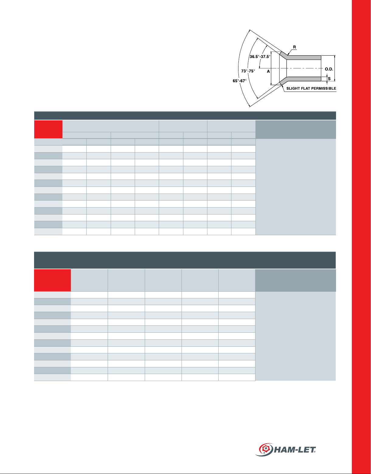
Perform aring according to SAE J533. See Fig. 2.
See Table 1 below for dimensions.
TABLE 1: FLARING
Nominal
Tube O.D
inch mm inch mm inch mm
Max Min Max Min ±0.02 ±0.5 Max Min
1/8
3/16
1/4
5/16
3/8
1/2
5/8
3/4
7/8
1
1 1/8
1 1/4
1 1/2
Dimensions are for reference only, and subject to change without notice.
0.20 0.18 5.08 4.58 0.03 0.8 0.035 0.88
0.28 0.26 7.11 6.61 0.03 0.8 0.035 0.88
0.36 0.34 9.14 8.64 0.03 0.8 0.065 1.65
0.43 0.40 10.92 10.16 0.03 0.8 0.065 1.65
0.49 0.46 12.44 11.69 0.04 1.0 0.065 1.65
0.66 0.63 16.76 16.01 0.06 1.5 0.083 2.1
0.79 0.76 20.06 19.31 0.06 1.5 0.095 2.41
0.95 0.92 24.13 23.37 0.08 2.0 0.109 2.76
1.07 1.04 27.17 26.42 0.08 2.0 0.109 2.76
1.20 1.17 30.48 29.72 0.09 2.3 0.12 3.04
1.38 1.35 35.05 34.29 0.09 2.3 0.12 3.04
1.51 1.48 38.35 37.60 0.09 2.3 0.12 3.04
1.73 1.70 43.94 43.18 0.11 2.8 0.12 3.04
A
Single Flare Diameter
R S
Figure 2
DEBURRING PRIOR
TO FLARING
CONNECTORS
To en su re sati sf act or y a re pro duc ti o n,
tu be end de bu r ri ng mi gh t be requ ir ed
prior to aring. It is usually necessary
to break the inside corner smoothly
before single aring. In addition,
some non-ferrous tubing is normally
required to eliminate the cutoff burr,
wh ich mig ht oth erw i se cre ate lea ka g e
pa ths acr oss a sub s ta nti al po rti on of
the are. Smoothly breaking the outside
corner prior to single aring, or both
the outside and inside corners prior
to dou bl e a r in g, is ac cep ta b le for any
tube material to minimize splitting.
TABLE 2: ALLOWABLE WORKING PRESSURE RATINGS
(CAPABLE OF 4’’ TO 1’’ MIN. BURST)
Nom. SAE
Dash Size
Nom. Tube O.D
Inches
37° Flare
Straight Thread
Nom. Pipe
Size
SAE St.Threads
Union and
Bulkhead
2 1/8 5/16" - 24 1/8" 5000 5000
3 3/16 3/8" - 24 1/8" 5000 5000
4 1/4 7/16" - 20 1/8" 5000 5000
5 5/16 1/2" - 20 1/8" 5000 5000
6 3/8 9/16" - 18 1/4" 5000 5000
8 1/2 3/4" - 16 3/8" 4500 4000
10 5/8 7/8" - 14 1/2" 3500 3000
12 3/4 1
14 7/8 1
16 1 1
20 1
24 1
32 2 2
1/4 1 5/8" - 12 1 1/4" 2500 1150
1/2 1 7/8" - 12 1 1/2" 2000 1000
1/16" - 12 3/4" 3500 3000
3/16" - 12 3/4" 3000 2500
5/16" - 12 1" 3000 2000
1/2" - 12 2" 1500 1000
Fittings with
Pipe Threads
NOTE:
As man y fa ct ors in uen ce the pre s su re
at which a system will or will not
perform satisfactorily, values shown
in Table 2 should not be construed
as guaranteed minimum.
HAM-LET ADVANCED CONTROL TECHNOLOGY
125
 Loading...