

Hamilton Home Products B436739 User Manual
PLEASE READ TEMPLATE FIRST
Pad retainer
Electric valve
(HSA 084)
Water diffuser (HPC 004)
12 HF Humidifier
Electronically controlled FLOW-THRU model
This humidifier MUST be connected to a drain.
REPLACEMENT PA RT NUMBERS IN BRACKETS
VER SION 5 - August 2007
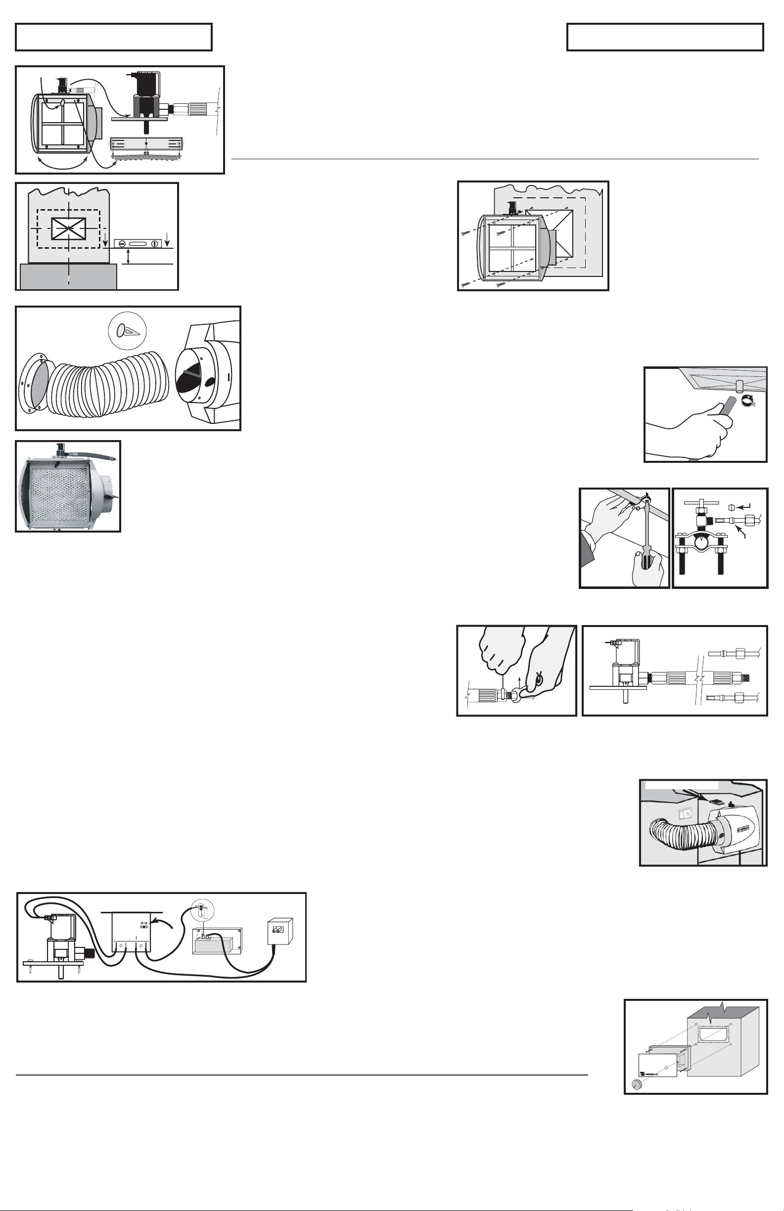
1 Assembling the unit
This unit is reversible. Although not mandatory, use on the hot air duct will improve performance. Find the best location and determine how
the humidifier will be installed. Select the top. Install and fasten the water diffuser, the long black plastic piece, with two screws #6 x 1/2"
inside the top of the humidifier. Install the electric valve (mounted on a plastic bracket) outside of the top of the humidifier. While supporting
the water diffuser with one hand, insert the plastic tube protruding from the valve into the hole in the middle of the top part of the humidifier
making sure that the plastic tubing is firmly seated in the hole of the water diffuser. Fasten the valve assembly to the unit with 4 screws # 6 x
1/2" (Kit #10). Finally, install the plastic pad retainer by snapping it in the hole located in the middle of the humidifier frame.
Warning : Always check that you are not about to cut or drill into any air conditioning or electrical accessory during installation.
This line
must be level
4''+
2 Cutting the opening
The preferred installation is to mount the humidifier on the warm air
duct, though it can be mounted on either duct. On whichever duct you
choose to install the humidifier, you must draw a level line. If mounting
on the warm air duct, make sure the line is at least 4 inches above the
furnace housing for clearance of the drain tube.
Attach the template to the duct. Punch and drill the four corners for
the opening and the four fastening holes with a 3/32” drill. Remove
the template and complete the opening outline with a marker. Cut the
3 Installing the unit
Install the unit in the opening. Use the
four screws (#8 x 3/4") to attach the
humidifier body to the duct. The ribs
around the humidifier back opening
must fit into the rectangular opening in
the duct. Check that the humidifier
body is level from side to side. Then
fasten the unit completely.
opening in the plenum. Beware of sharp edges in the duct.
4 Installing the collar and the flex duct (HSA 130)
Place the 6" plastic collar in a convenient location on the opposite duct. Trace a circle for the opening, then cut the hole with tin snips.
Affix the collar with four screws (#8 x 1/2"). Slide the damper assembly into the side opening of the humidifier until it snaps. Make sure to
position the damper knob in front of the unit. Measure the required flex duct length to the plastic collar so it does not sag. Cut the excess
portion. Slide the flexible duct on the air take-off collar and secure it by inserting the plastic pins through
the vinyl in between two reinforcement wires.
5 Installing the drain tube (HPC 133)
Select a convenient drain location for running the drain tube. Before you connect the tube to the drain
fitting, slip the hose clamp over the tube. Push the drain tube (1/2" I.D.) over the drain fitting located at
the bottom of the unit and secure it in place with the hose clamp. Make sure the tube has no bends
and the water can flow easily in a straight manner to the drain without accumulating in the tube.
6 Installing the evaporator pad (EP 037)
The pad is enclosed in a plastic frame having molded markings that clearly indicates the bottom. Slide the pad into the bottom
part of the humidifier, the little bump at the top facing to you, then push the pad against the back opening of the humidifier. Lock the pad in place with the pad
retainer.
7 Installing the water supply valve (HSA 140) on a copper pipe
A plastic bag contains a brass valve and all the material required to install the water supply valve. Water is
taken from the nearest cold water pipe suitable for the supply valve installation. Do not install this on a
plastic pipe. Shut off the main water valve.
Brass
Note : Please make sure that the piercing pin is completely recessed into the valve body by turning the handle counter clockwise.
Do not use the saddle valve to adjust water flow. It is designed to be fully open or closed.
• Assemble one side of the top clamp to the bottom clamp with a screw and a nut.
• Make sure that the rubber gasket is in place over the piercing needle and position the valve assembly on the copper water line.
• Assemble the other side of the top clamp to the bottom clamp with the remaining screw and nut.
• Tighten the two screws so that the valve is firmly attached to the water pipe. The two sides of the clamp must be parallel.
8. Connecting the water supply tubing (HSA 170) to the water hammer absorber (HSA 215) and the valve (HSA 084)
• This water hammer absorber is connected to the electric valve in factory.
• Install the water supply tubing on the side of the water hammer absorber that has a compression
fitting to receive the supply tubing.
• Slip the brass compression nut onto the plastic supply tube, then the nylon sleeve with its most
tapered end towards the end of the tube. Finally, install a brass insert into the end of the
plastic tubing.
• Push the supply tube fully into the brass compression fitting. Tighten the brass compression nut
with small wrenches, without stripping the threads, using the double wrench method in order to
apply the torque on the fitting only.
• Then do the same operation at the other end of the supply tube and make the connection to the saddle valve previously installed on the copper supply pipe.
• Turn the valve handle completely clockwise until it stops. This will pierce the copper pipe and close the valve.
• This saddle valve is designed to be fully open or closed. Do not use it to adjust the water flow.
NOTE : The brass sleeve supplied with the brass valve Kit #10 is to be used only if the plastic tubing is replaced by copper tubing (not recommended).
9 Installing the electronic controller (HSA 044)
•
The HSA044 is factory set at NO TEMP, with settings for HIGH TEMP and LOW TEMP. The NO TEMP setting is used when the humidifier is supplied
power from the furnace. The unit will run as long as there is power AND the humidistat is calling for more humidity.
•
The LOW TEMP setting is used for furnaces that generate less heat, such as those with a heat pump. The unit may operate for a short while after the
furnace has stopped due to residual heat in the duct.
•
The HIGH TEMP setting is used for furnaces that generate more heat, typically oil or gas furnaces. You may have to try both settings to see which one is
right for you.
•
To choose the setting on the controller, place the jumper on the corresponding terminal pins, as shown on the controller. For HIGH and LOW settings, the controller must
be installed on the warm air duct with two screws (#8 x ½”). There are two lights on the controller: the green LED means there is power to the controller and the blue LED
cycles on as the valve opens. When switched ON by the humidistat, the controller opens the electric valve for approximately 2 seconds and then closes the valve for another
30, and so on. Please use Template #3 and drill the 3 holes.
Nylon
Copper
Plastic
Electronic Controller
Electronic Controller
(HSA 044)
HSA 044
24VAC
VALVE
Jumper
& Pins
Transformer
(HSA 200)
2
3
10 Wiring between the humidistat (HSA 100), the transformer (HSA 200)
and the electronic controller (HSA 044)
1- Push the two quick connectors on the humidistat terminals identified COM and NO.
2- Split the wire coming from the transformer in two, long enough to connect one end to the humidistat
(terminal COM) and the other one to the electronic controller (terminal 24VAC).
3- Use the separate piece of single wire to connect the other terminal 24VAC of the controller to the terminal NO.
Valve (HSA 084)
Humidistat
(HSA 100)
4- Use the double wire to connect the valve to the two terminals (terminal VALVE) in the centre of the controller.
NOTE : The quick connectors at the end of the double wire are not the same size.
The small ones go to the controller and the bigger ones to the electric valve.
11 Installing the humidistat (HSA 100) and the transformer (HSA 200)
This humidifier is supplied with a transformer that can be plugged in to any 120V electric outlet. The humidistat is a duct mounted type.
It is better to mount the humidistat on the RETURN duct because it will detect the air being returned to the furnace without being disturbed by a sudden
increase in moisture (as from a kitchen or bathroom). This will offer better humidity control.
Kit No. 4 contains all the material you need to install the humidistat.
Template
• The humidistat should be installed on a flat and vertical surface of the RETURN duct a minimum of 6 inches above the humidifier.
40
• Attach the humidistat template (#2) on the duct.
Warning : Always check that you are not about to cut or drill into any air conditioning or electrical accessory during installation.
30
50
20
10
60
• Mark and drill the mounting holes and cut an opening for the humidistat.
• Run the control wires through an opening located at the bottom of the front panel of the humidistat.
• Hold the wires while you install the humidistat in the opening. Check that the metal of the duct neither touches the connections nor cuts the wire insulation. Then fasten the humidistat
to the duct. The humidistat mechanism is exposed in the duct. Temporarily install the control knob on the humidistat.
12 Humidifier Start-up.
Open the saddle valve, put the furnace power back on and start the furnace in a heating cycle. Set the humidistat at the maximum setting.
After a few ON/OFF cycles of the electric valve, you should see water flowing through the drain tube. Check that the water is evenly distributed by the water diffuser across the pad. Carefully check
that both ends of the water supply tube are firmly held in place by their respective compression fitting. After peeling off the backing, affix the faceplate to the cover of the humidistat and re-install the
control knob. Set the humidistat according to the recommended setting on the label. Check the system several times to make sure there is a free flow in the drain tube and there is no leak before
leaving the installation unattended. When everything is working fine, affix the adhesive nameplate on the humidifier cover.

12 HF Humidifier
Owner's Instructions for Electronically controlled FLOW-THRU Humidifier
Operating and Maintenance Tips - Warranty.
1. Principle of operation
• This humidifier uses a vertical evaporator pad, wetted by a pulsed water flow. Warm air is by-passed from
the warm air plenum and forced through the evaporator pad. Humid air is drawn back into the return duct.
• The pad is enclosed in a plastic frame with a marking that clearly indicates the bottom. It is designed to
retain water before it is evaporated. Any excess water is sent to the drain.
• All flow-through humidifiers improve performance and evaporative capacities if they are used
with constant blower operation. However, this unique pulse action model optimizes performance and
reduces water consumption by up to 80%.
• When the furnace is producing heat and the humidistat is calling for humidity, the electronic module
allows a controlled water flow on the evaporator pad. It opens the electric valve for an average of 2
seconds and then closes the valve for another 30 seconds, and so on, thus giving the time for the water
dispersed on the pad to be evaporated in the system, without wasting a lot of water which normally would
go directly to the drain. This is one of the main features of this model and it saves up to 80% of water
consumption. It is normal to have a bit of water flowing in the drain tube, though. This flushing-away
method removes the dissolved minerals that are left on the pad in a normal evaporation process before
they settle and dry up on parts that are in contact with water. The little water waste is a "rinse n' drain cycle".
2. Adjusting the humidity level in your home
• A relative humidity environment of 40% is recommended. Please refer to the table on the humidistat front
plate to help determine the proper level.
Outside Recommended
Temperature Setting
- 22°F (-30ºC) 15 %
- 13°F (-25ºC) 20 %
- 4°F (-20ºC) 25 %
+ 5°F (-15ºC) 30 %
+ 14°F (-10ºC) 35 %
above 23°F (-5ºC) 40 %
• At the beginning of the heating season it might take some time (a few days) to build up the humidity to
the comfortable level you want. Depending on the original dryness of the house, carpets, furniture and
wood will absorb moisture before you would really feel a dif ference.
• If your house remains unoccupied during the winter season, adjust the humidistat to a lower setpoint in
order to prevent condensation.
3. A few tips
• Do not use the supply valve (installed on the supply line) to regulate the water flow. This type of valve is
designed to be completely opened or closed.
• Do not allow the drain tube to fill with water in bends, elbows or kinks. Water could accumulate in them
and that could lead to deposit build-up. This could also create a back pressure preventing
the
water
from
flowing
naturally and cause an overflow.
4. Annual Maintenance
To replace the evaporator pad :
1- Unplug the transformer from the wall power supply.
2- Open the humidifier by removing the plastic screw on the side of the cover.
3- Unlock the evaporator pad by turning the little plastic retainer at the top of the pad.
4- Remove the old pad and replace it by a new one while checking the printed marking that clearly indicates
the bottom of the pad.
5- Lock the new pad in place.
6- Put the cover back and secure it with the plastic screw.
Note : Depending on the quality of water, it is recommended to replace the evaporator pad once per
heating season.
5. Summer season
• If the system is used in air conditioning during the summer, reduce the air volume going through the
humidifier by closing the air damper located on the side of the humidifier. The control button shows
the actual position of the damper.
• It is recommended to simply shut off the humidifier system :
1- Close the water supply valve.
2- Turn the humidistat knob to the "OFF" position.
3- Unplug the transformer.
6. Warranty
This humidifier is guaranteed against any defects in material and workmanship, under normal use, for
one (1) year from the date of purchase. The frame and door are guaranteed for life against defects in
material and workmanship, under normal use. This warranty applies only if the unit is properly installed
and operated according to the instructions provided with this product. This warranty will not cover defects
due to misuse or faulty installation. The manufacturer will not be held responsible for any bodily injuries or
damages to personal property or real estate, whether caused directly or indirectly by the humidifier.
If warranty service is required during the warranty period, the manufacturer will, at its sole discretion,
repair or replace the product, without charge, upon delivery of the product where it was purchased, with
proof of purchase.
7. Questions
Please keep this telephone number handy for assistance:
1-800-879-0123
or
www.HamiltonHomeProducts.com
 Loading...