

Page 1
SERVICE MANUAL
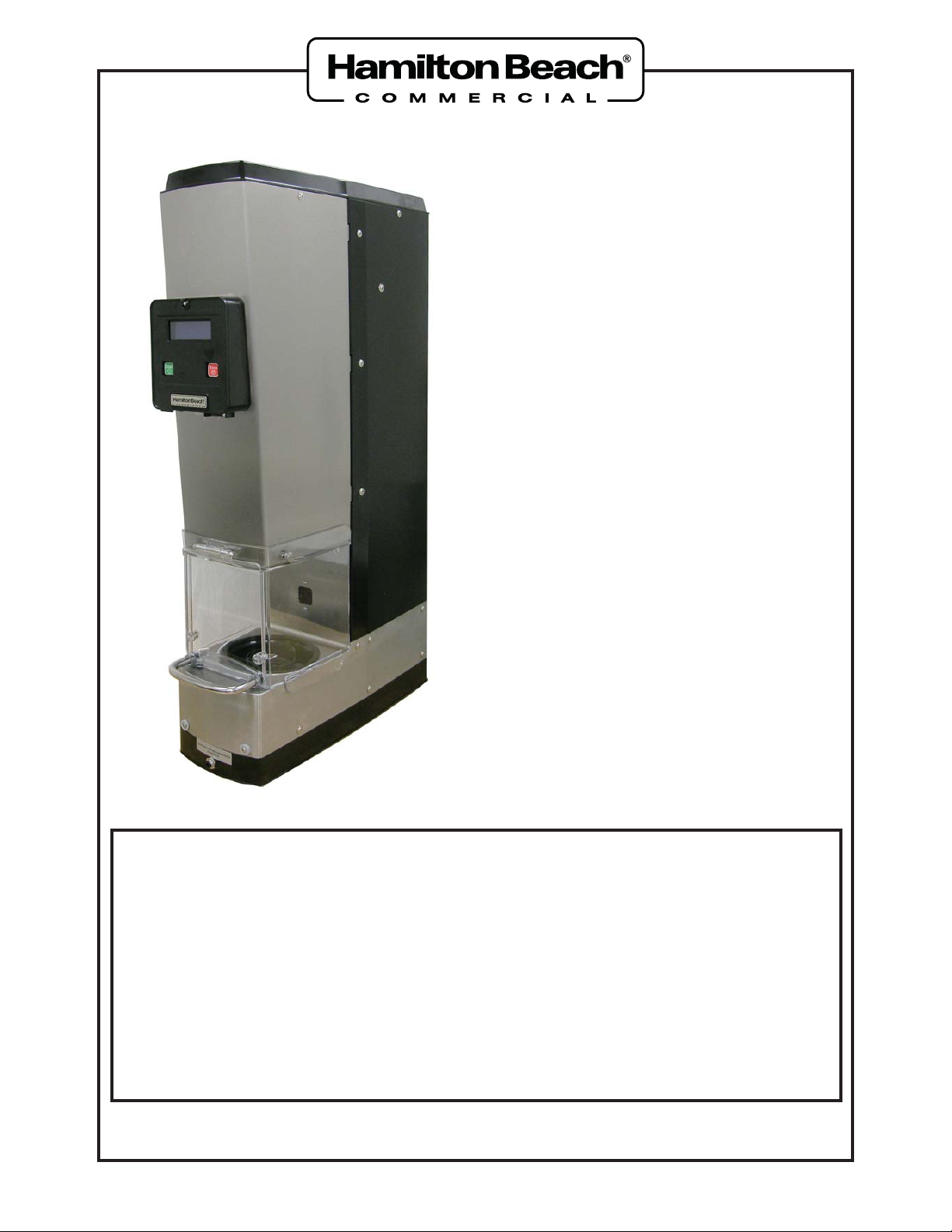
SmartServe™ Drink Mixers
MIC2000
BIC2000
– NOTICE –
This Manual is prepared for the use of trained Service T echnicians and should
not be used by those not properly qualifi ed.
This Manual is not intended to be all-encompassing. You should read, in its
entirety , the repair procedure you wish to perform to determine if you have the
necessary tools, instruments, and skills required to perform the procedure.
Procedures for which you do not have the necessary tools, instruments, and
skills should be performed by a trained Service Technician.
Reproduction or other use of this Manual, without the express written consent
of Hamilton Beach, is prohibited.
520008300
www.commercial.hamiltonbeach.com
08/14
Page 2

SmartServe™ Drink Mixers Service Manual
TABLE OF CONTENTS
GENERAL
Safety Information ..................................................................................................................4
Technical Services .................................................................................................................5
Introduction ............................................................................................................................5
Tools and Materials ................................................................................................................6
PREVENTATIVE MAINTENANCE
Preventative Maintenance......................................................................................................7
General Cleaning ..............................................................................................................7
Sanitizing ..........................................................................................................................8
Inspection Checklist ..........................................................................................................8
TROUBLESHOOTING
Component Functions ............................................................................................................9
Control Board Connections ..................................................................................................10
Interface Display Board Connections ...................................................................................14
Power Supply Connections ..................................................................................................15
Wiring Diagrams ...................................................................................................................16
MIC2000 .........................................................................................................................16
BIC2000 ..........................................................................................................................17
Water and Valve Diagrams...................................................................................................18
MIC2000 .........................................................................................................................18
BIC2000 ..........................................................................................................................18
Component Testing ..............................................................................................................19
Troubleshooting Guide .........................................................................................................19
Error Code Troubleshooting .................................................................................................22
REMOV AL AND REPLACEMENT
Safety Shield Assembly........................................................................................................26
Top Cover .............................................................................................................................28
Operator Interface Panel Assembly .....................................................................................30
Breaker Switch .....................................................................................................................32
Interface Display Board ........................................................................................................33
Touch Pad ............................................................................................................................34
Cup Guard & Shield Assembly .............................................................................................35
Motor Assembly....................................................................................................................38
Linear Actuator Assembly.....................................................................................................41
48VDC Power Supply ..........................................................................................................44
Control Board Assembly.......................................................................................................47
Sensor Assembly (Home Position).......................................................................................50
Sensor Assembly (Cup Present) ..........................................................................................52
Cup-In-Place Sensor (Infrared) ............................................................................................55
Shield Door Sensor ..............................................................................................................60
Wash Chamber Assembly ....................................................................................................65
© Hamilton Beach Brands, 2014
Page 2 of 92 520008300 08/14
Page 3
SmartServe™ Drink Mixers Service Manual
Water Solenoid .....................................................................................................................70
Wash Chamber Gasket ........................................................................................................72
Water Manifold (MIC2000 Only) ...........................................................................................74
Cup Shield Gasket ...............................................................................................................75
REPLACEMENT PARTS LIST
SHIELD DOOR ASSEMBLY & PANELS ..............................................................................76
OPERATOR INTERFACE PANEL ASSEMBLY ....................................................................78
CONTROL BOARD ASSEMBL Y AND SENSORS ...............................................................80
LINEAR ACTUATOR, MOTOR, & CUP GUARD (BIC2000) ................................................82
LINEAR ACTUATOR, MOTOR, & CUP GUARD (MIC2000) ................................................84
MOTOR ASSEMBL Y ............................................................................................................86
WASH CHAMBER & WATER LINES (BIC2000) ..................................................................88
WASH CHAMBER & WATER LINES (MIC2000) .................................................................90
Page 3 of 92 520008300 08/14
Page 4
SmartServe™ Drink Mixers Service Manual
SAVE THESE INSTRUCTIONS
REVIEW ALL SERVICE INFORMATION IN THE APPROPRIATE SERVICE MANUAL AND
TECHNICAL SHEETS BEFORE BEGINNING REPAIRS.
Pride and workmanship go into every product to provide our customers with quality products.
It is possible, however, that during its lifetime, a product may require service. Products should
be serviced only by a qualified service technician who is familiar with the safety procedures
required in the repair and who is equipped with the proper tools, parts, testing instruments, and
the appropriate service manual.
Safety Information
We have provided many important safety messages in this manual and on the appliance.
ALWAYS read and obey all safety messages.
This is the safety alert symbol.
This symbol alerts you to hazards that can kill or hurt you and others. All safety messages will
be preceded by the safety alert symbol and the word “DANGER”, “WARNING”, or “CAUTION”.
These words mean:
DANGER
IMMEDIATE HAZARDS THAT WILL RESULT IN SEVERE PERSONAL INJURY OR
DEATH.
WARNING
Hazards or unsafe practices that COULD result in severe personal injury or death.
CAUTION
Hazards or unsafe practices that COULD result in minor personal injury or product or
property damage.
General
Page 4 of 92 520008300 08/14
Page 5
SmartServe™ Drink Mixers Service Manual
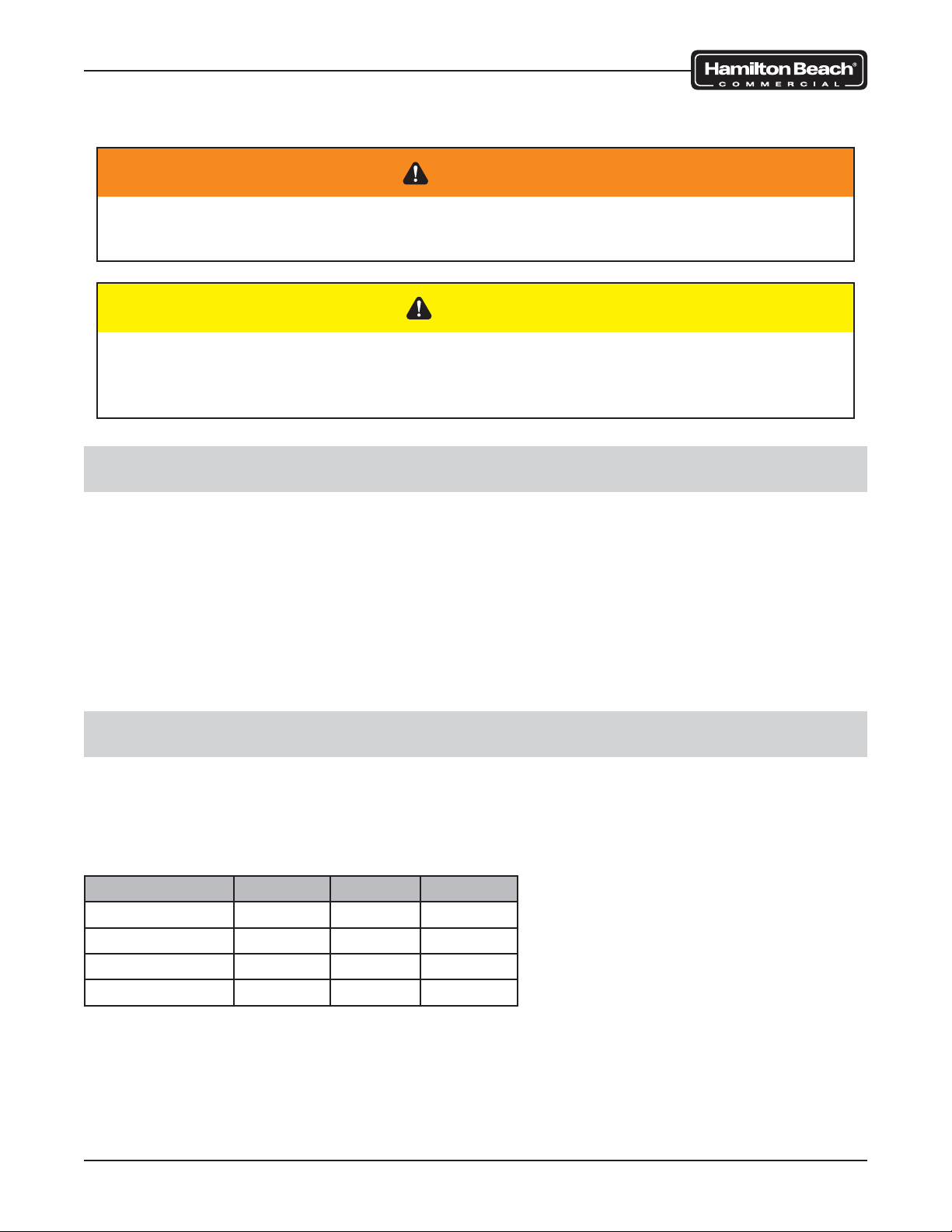
All safety messages will identify the hazard, describe how to reduce the chance of injury, and
describe what can happen if the instructions are not followed.
WARNING
To avoid risk of serious injury or death, repairs should not be attempted by
unauthorized personnel.
CAUTION
Hamilton Beach will not be responsible for any injury or property damage from
improper service procedures. If performing service on your own product, you must
assume responsibility for any personal injury or property damage that may result.
Technical Services
Visit www.commercial.hamiltonbeach.com for technical service information.
To change your program or create a new one, contact your salesperson.
For assistance, copy of an existing program, or replacement parts, call our Technical Services
phone number:
866-285-1087 or 910-693-4277
8 a.m. – 5 p.m. EST Monday – Friday
Introduction
This manual covers the MIC2000 and BIC2000 Drink Mixer. Detailed information about the
operation and cleaning of these machines can be found in the Use & Care Manual. Contact
your salesperson to obtain a copy or visit www.commercial.hamiltonbeach.com.
The operating specifications are as follows:
Model Volts Hertz Phase
MIC2000 120 60 1
BIC2000 120 60 1
MIC2000-CE 230 50/60 1
BIC2000-CE 230 50/60 1
General
Page 5 of 92 520008300 08/14
Page 6
SmartServe™ Drink Mixers Service Manual
Tools and Materials
CAUTION
Do not use power tools to remove hardware. Damage to the hardware or the machine
may occur. Do not lose hardware.
• Standard set of hand tools
• VOM with AC current tester (any quality VOM with a sensitivity of at least 20,000 ohms
per volt can be used)
• Loctite No. 242
• Adhesive remover
General
Page 6 of 92 520008300 08/14
Page 7
SmartServe™ Drink Mixers Service Manual
Preventative Maintenance
To keep the machine operating properly, it is essential that the machine is cleaned regularly.
Whenever service is performed on the machine, a visual inspection of the components should
be performed to ensure optimal operating conditions.
General Cleaning
The shield will need to be cleaned depending on the application and how many cycles are
completed in a given period.
1. Clean SmartServe™ using a cleaning solution of hot water (less than 115°F/46°C) and
a nonsudsing detergent according to the package directions.
2. Turn ON (I) by pressing the power switch under the control panel on the right side.
3. Remove cup holder.
NOTE: MIC models do not require daily cup holder removal.
4. Press MENU and select “LOWER SHIELD.” Press START.
5. Turn power OFF (O).
6. Remove the two thumbscrews from the door assembly and pull off the door assembly.
7. Push the tab on the front of the cup guard assembly while turning the splash shield to
the left. Let splash shield rest in the wash chamber.
8. Lift the cup guard assembly upward approximately 3” to allow room to remove the
splash shield.
CAUTION
Blades are sharp.
9. Wipe the wash chamber, cup lid, and upper part of cup guard assembly with a soft cloth,
bottle brush, or sponge dampened with the cleaning solution.
10. Immerse cup holder, door assembly, and splash shield in cleaning solution and wipe
with a soft cloth or sponge.
NOTE: PARTS ARE NOT DISHWASHER-SAFE.
11. Rinse cup holder, door assembly, and splash shield in clean water; allow to dry.
12. Reassemble the cup holder, splash shield, and door assembly.
13. Turn power ON (I) and allow the machine to return to its HOME position; press the
FLUSH button to flush the water lines.
14. Following the flush cycle, insert a cup filled with cleaning solution and run any preprogrammed cycle. DO NOT OPEN DOOR WHILE CYCLE IS IN PROGRESS!
15. When cycle is finished, open the door, remove the cup, and pour the solution into the
wash chamber. Close the door. The unit will automatically run through a rinse cycle.
16. Follow sanitizing instructions.
Preventative Maintenance
Page 7 of 92 520008300 08/14
Page 8
SmartServe™ Drink Mixers Service Manual
Sanitizing
The SmartServe™ must be sanitized before daily use.
1. Wash SmartServe™ following instructions in “General Cleaning.”
2. Sanitize using 1 Tablespoon (15 mL) of bleach per 1 gallon (3.8 liter) of clean, cool
water (60°F/16°C), mixed according to the instructions on the bleach. (If using a
sanitizing solution other than bleach, test the concentration using commercial test strips.
Concentration levels should be between 100 and 200 parts per million of bleach to
water.)
3. Turn ON (I) by pressing the power switch under the control panel on the right side and
flush system as prompted.
4. Insert a cup filled with sanitizing solution and run any pre-programmed cycle (using the
1–3 and A–C buttons). DO NOT OPEN DOOR WHILE CYCLE IS IN PROGRESS!
5. Allow cycle to finish. Open the door, remove the cup, and pour the solution into the
wash chamber.
6. NOTE: For MIC models, use the sanitizing syringe to inject at least 50 mL of sanitizing
solution into the sanitizing port. Remove syringe and set aside.
7. Remove the two thumbscrews from the door assembly and pull off the door assembly to
allow the equipment to dry overnight. If equipment is needed immediately, press FLUSH
button before programming equipment for a drink.
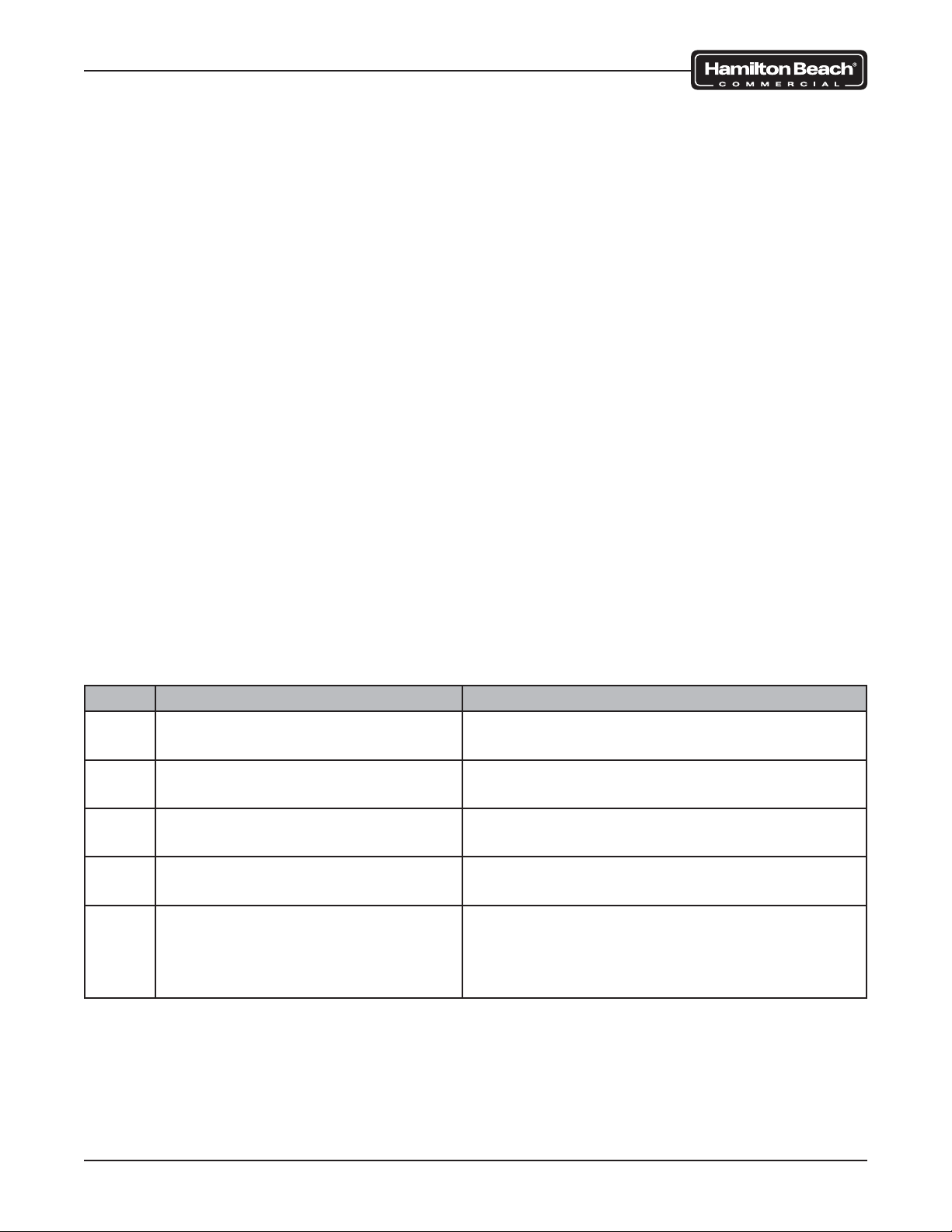
Inspection Checklist
Whenever service is performed on the machine, review this checklist to ensure the machine
operates efficiently.
Date Inspection Action
Check all water lines and connections for leaks.
Check all drain connections for
leaks.
Visually inspect all wires and wire
harnesses for wear.
Ensure all necessary wire ties are
secure and in place.
Observe the travel of the motor
on the linear actuator. The motor
should move freely without obstruction or resistance.
Repair or replace any items found leaking.
Repair or replace any items found leaking.
Repair or replace any damaged wires.
Replace any missing or broken wire ties.
Clean slide rods and apply a food safe lubricant to the lead screw and reroute any wire
harnesses or water lines that interfere with
operation.
Preventative Maintenance
Page 8 of 92 520008300 08/14
Page 9
SmartServe™ Drink Mixers Service Manual
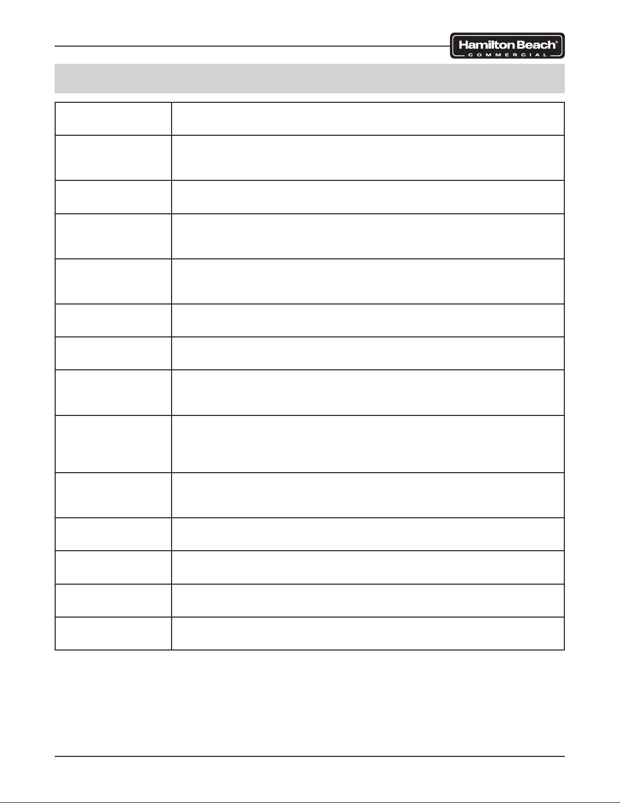
Component Functions
Motor
Linear Actuator
Power Supply
Control Board
Home Sensor
Cup Present
Sensor
Cup-In-Place
Sensor
Wash Chamber
Sensors
The motor is used to turn the blade assembly. It receives power
through the control board.
The linear actuator is used to lower and raise the motor and cup
guard/shield assembly during use. It receives power and is controlled
by the control board.
The power supply distributes 48VDC power to the control board to
operate the linear actuator motor and the valve(s).
The control board is the brain of the machine. It receives power from
the power supply and provides command logic to operate the machine.
The home sensor determines the highest position of the motor and
cup guard/shield assembly and establishes a starting point for the
linear actuator.
The cup present sensor lets the machine know if the linear actuator
has reached a position where it is acceptable to fl ush, rinse, or blend.
The cup-in-place sensor is an infrared sensor designed to determine
the presence of a cup in the mixing chamber.
The wash chamber sensors are embedded in the wash chamber
assembly. They are designed to sense when the cup guard is in the
wash chamber. These sensors are not present on all models.
Shield Sensor
Interface Display
Board
Touch Pad
Control Panel
Breaker Switch
Water Solenoid
Valve (1)
Water Solenoid
Valve (2)
The shield sensor is located under the wash chamber area. A magnet
in the safety shield assembly interacts with the sensor and requires
that the door be closed in order for the machine to operate. Some
models have two sensors.
The interface display board is located in the interface control panel.
The board receives input from the touch pad and sends the commands to the control board.
The touch pad is on the interface control panel. It is connected to the
interface panel control board with a ribbon style cable.
The breaker switch is located on the interface control panel. It controls power to the power supply and main control board.
This water solenoid controls the fl ow of water to the wash chamber
during RINSE and FLUSH cycles.
This water solenoid controls the fl ow of water to the drink mixing area.
Troubleshooting
Page 9 of 92 520008300 08/14
Page 10
SmartServe™ Drink Mixers Service Manual
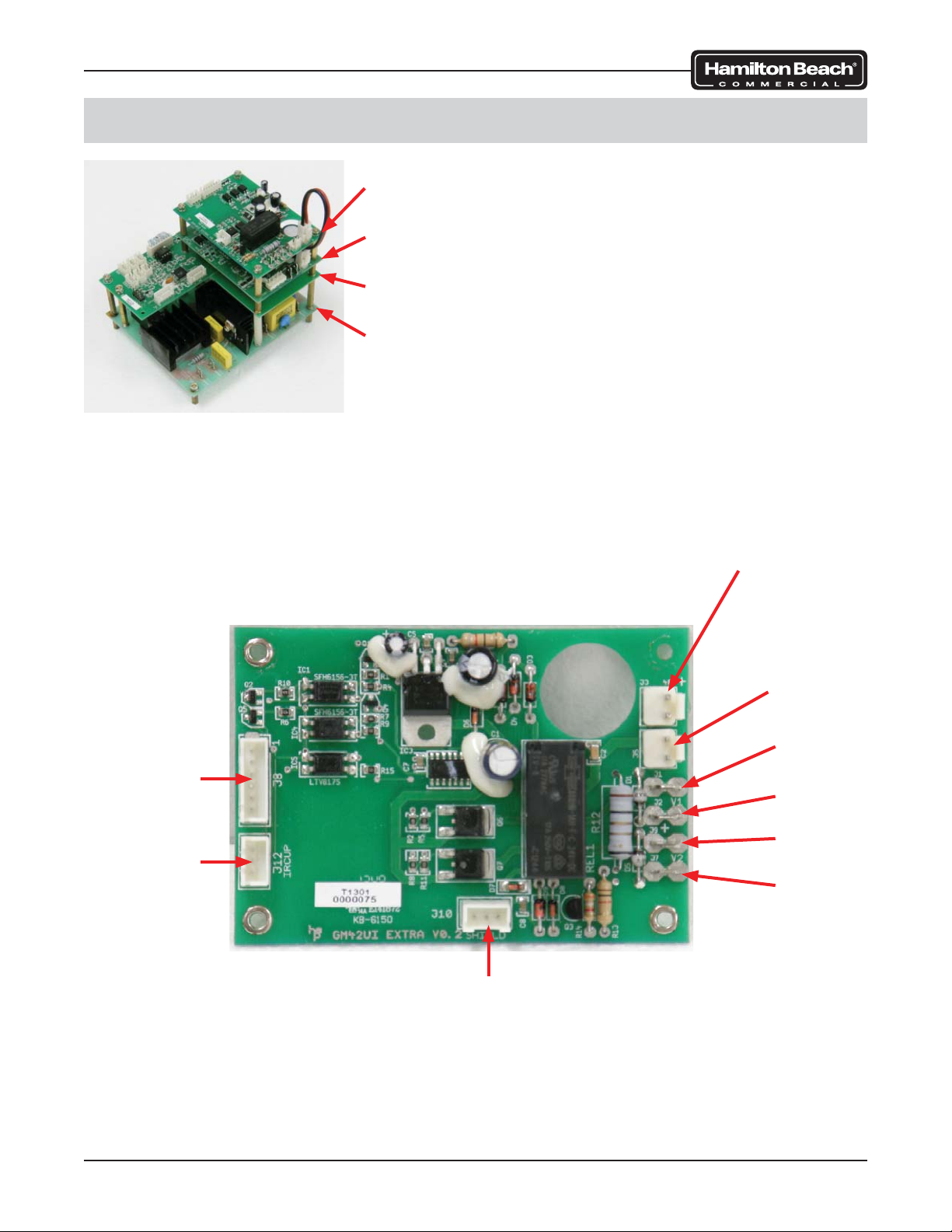
Control Board Connections
Control Board 1 (Solenoid and Sensor)
Control Board 2 (Linear Motor)
Control Board 3 (Command Logic)
Control Board 4 (Motor Power)
Control Board Assembly
To
Interface
Display Board
To
Cup-In Place
Sensor
Jumper
To Board 2
(2-Pin)
From Power
Supply
(V- & V+)
V1 (Black)
To Solenoid
V1 (White)
To Solenoid
V2 (Black)
To Solenoid
V2 (White)
To Solenoid
Troubleshooting
To Shield
(Door)
Sensor
Control Board 1 (Solenoid and Sensor)
Page 10 of 92 520008300 08/14
Page 11
SmartServe™ Drink Mixers Service Manual
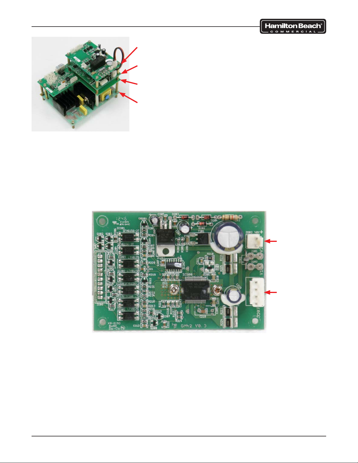
Control Board 1 (Solenoid and Sensor)
Control Board 2 (Linear Motor)
Control Board 3 (Command Logic)
Control Board 4 (Motor Power)
Control Board Assembly
Control Board 2 (Linear Motor)
Jumper
From Board 1
(2-Pin)
To Linear
Actuator
Motor
Troubleshooting
Page 11 of 92 520008300 08/14
Page 12
SmartServe™ Drink Mixers Service Manual
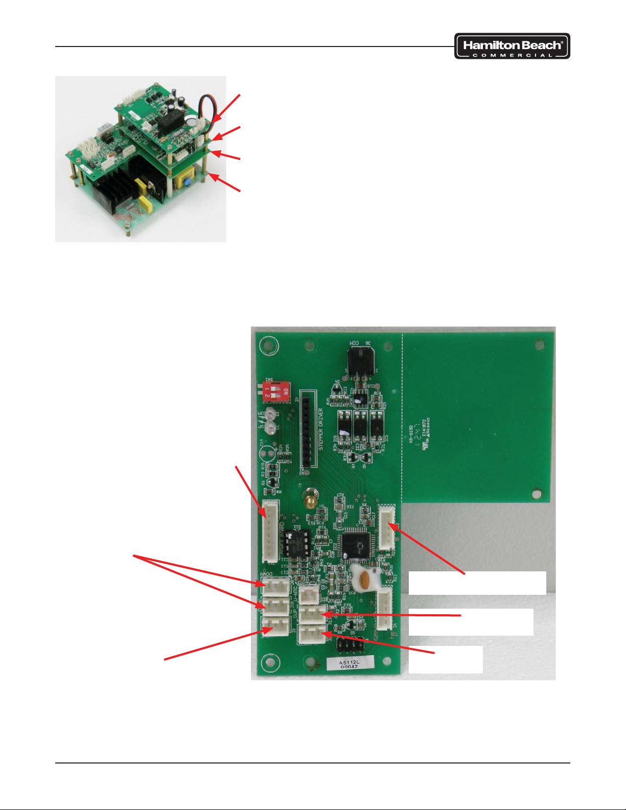
Control Board 1 (Solenoid and Sensor)
Control Board 2 (Linear Motor)
Control Board 3 (Command Logic)
Control Board 4 (Motor Power)
Control Board Assembly
To Wash
Chamber
Sensor
OR
To second Shield
(Door) Sensor
and Jumper
To
Home
Sensor
Jumper
From Board
4 (8-Pin)
To
Interface Display Board
To
Cup Present Sensor
To
Motor
Control Board 3 (Command Logic)
Troubleshooting
Page 12 of 92 520008300 08/14
Page 13
SmartServe™ Drink Mixers Service Manual
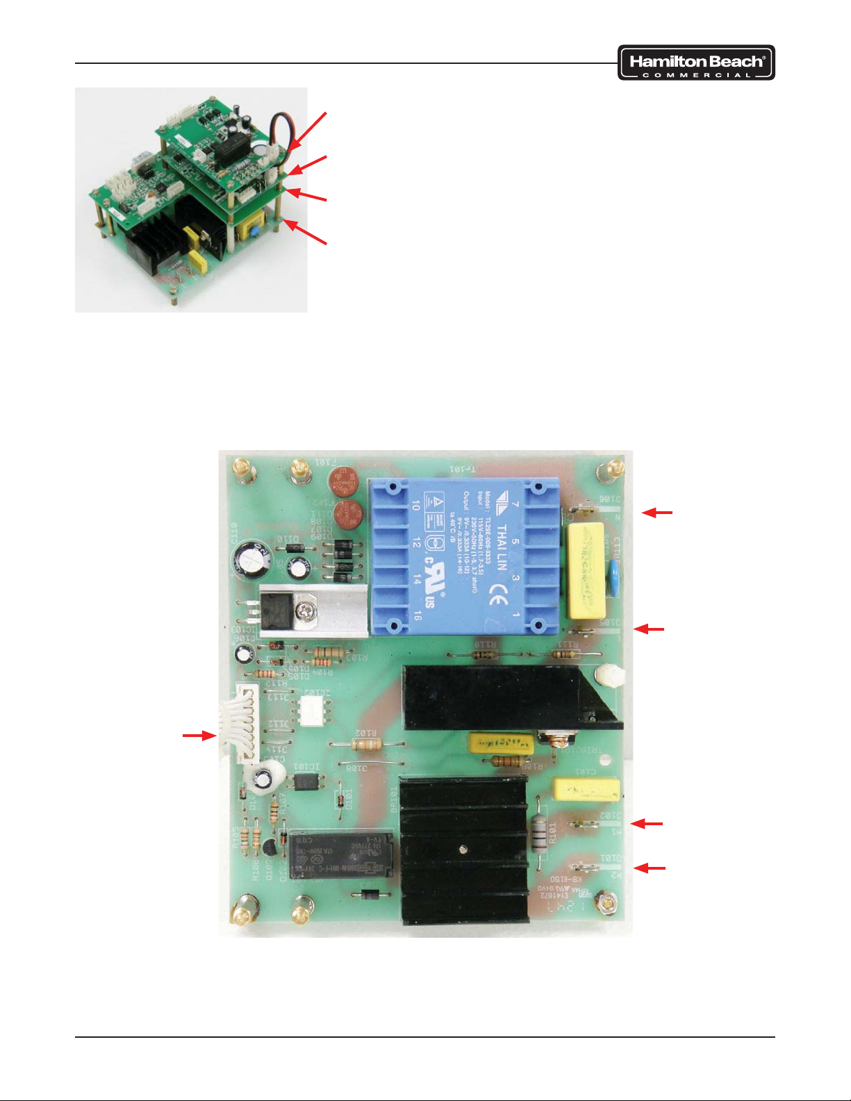
Control Board 1 (Solenoid and Sensor)
Control Board 2 (Linear Motor)
Control Board 3 (Command Logic)
Control Board 4 (Motor Power)
Control Board Assembly
Jumper
To Board 3
(8-Pin)
N
(White)
L
(Black)
From Main
Breaker
Switch
M1
(Black)
Motor
M2
(White)
Motor
Troubleshooting
Control Board 4 (Motor Power)
Page 13 of 92 520008300 08/14
Page 14
SmartServe™ Drink Mixers Service Manual
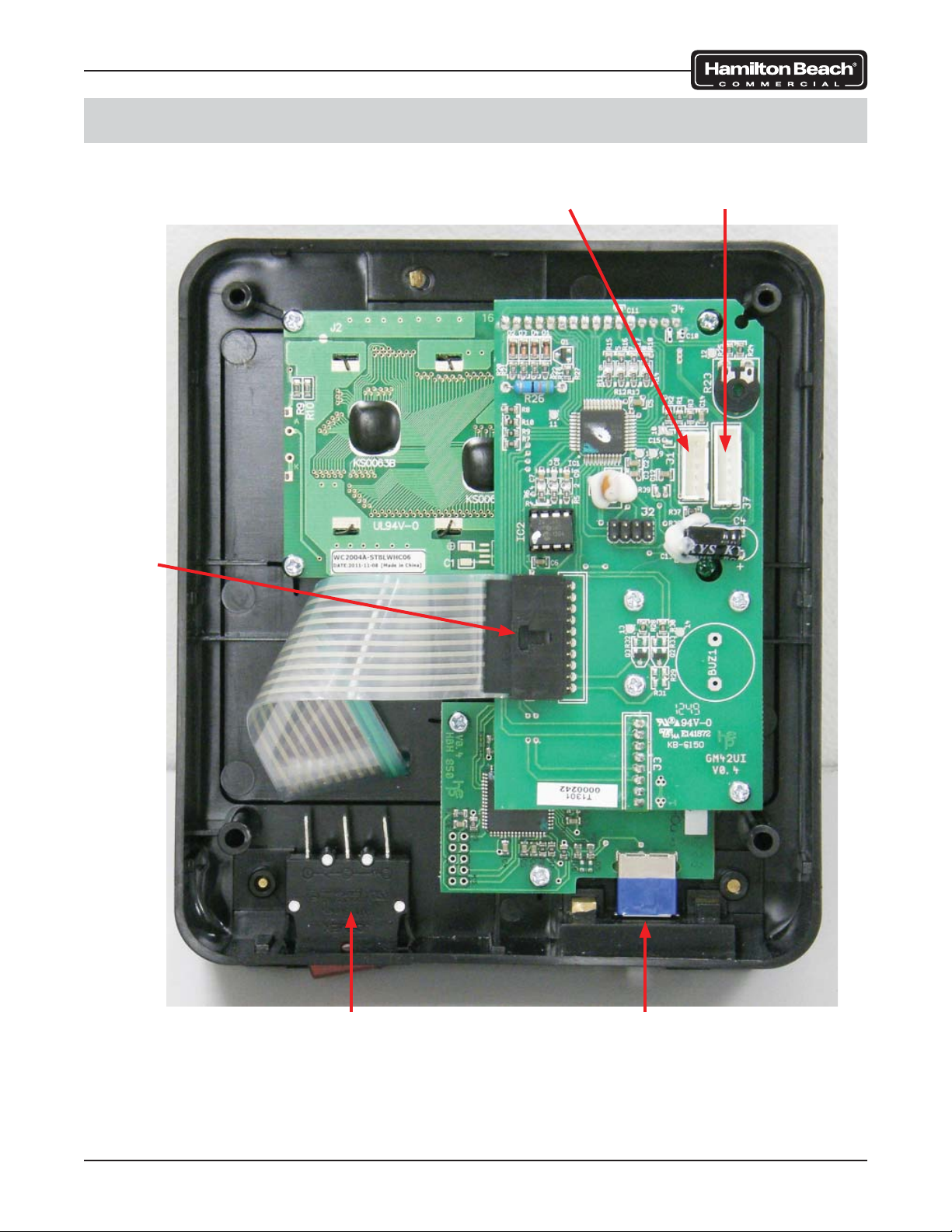
Interface Display Board Connections
Lock Tab
To Control
Board 3 (5-Pin)
To Control
Board 1 (6-Pin)
Troubleshooting
Breaker
Switch
USB Port
Page 14 of 92 520008300 08/14
Page 15
SmartServe™ Drink Mixers Service Manual
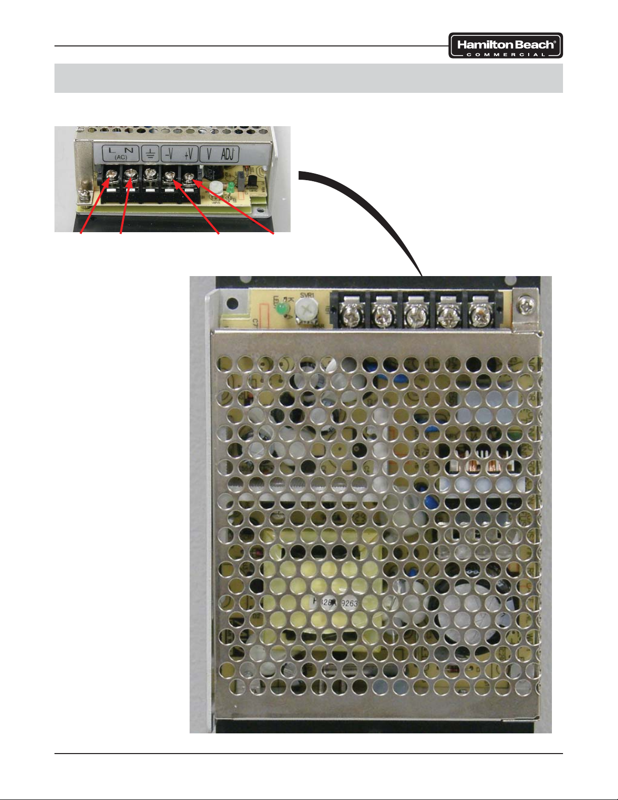
Power Supply Connections
48 VDC POWER SUPPLY
L
(Black)N(White)
V-
(Black/Red)V+(Red)
Troubleshooting
Page 15 of 92 520008300 08/14
Page 16
SmartServe™ Drink Mixers Service Manual
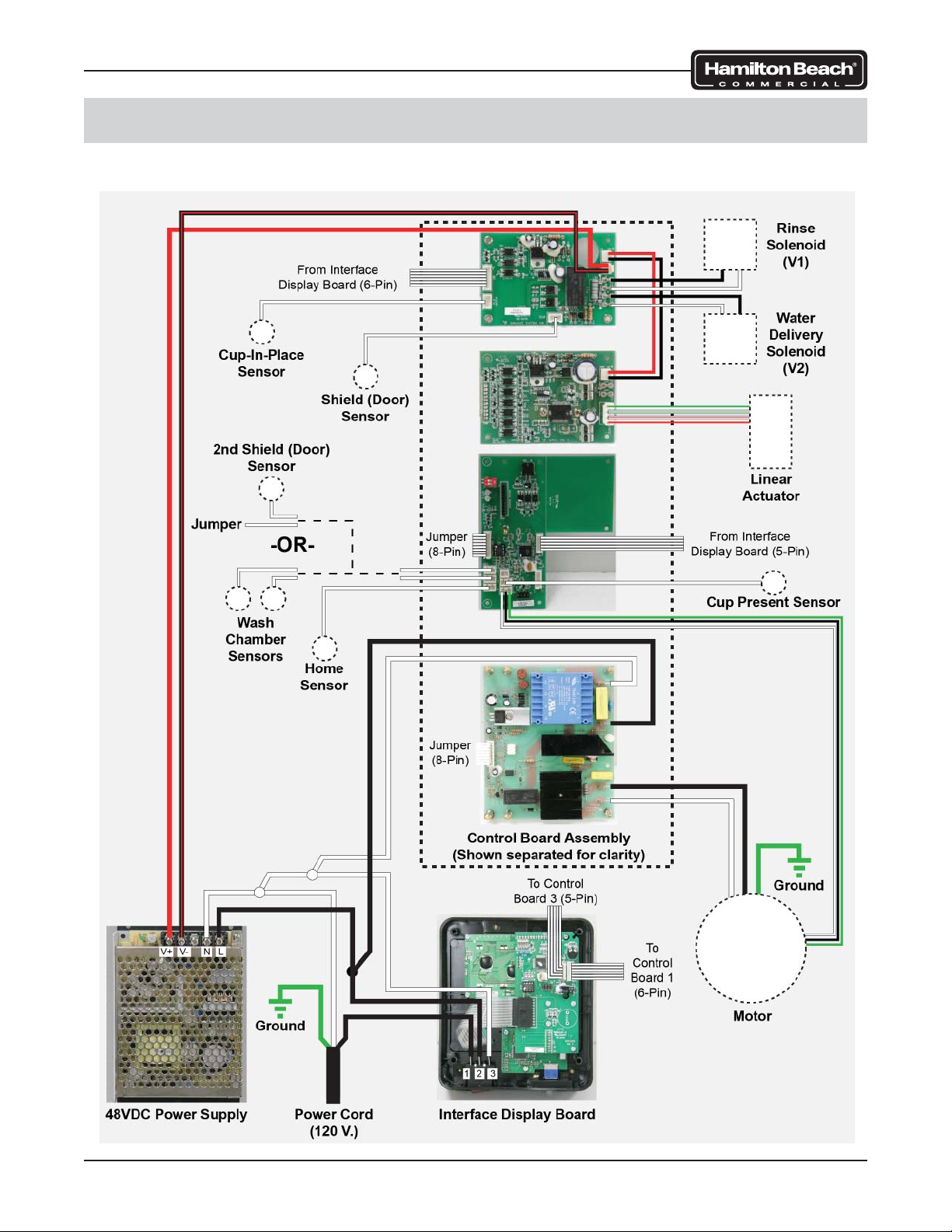
Wiring Diagrams
MIC2000
Troubleshooting
Page 16 of 92 520008300 08/14
Page 17
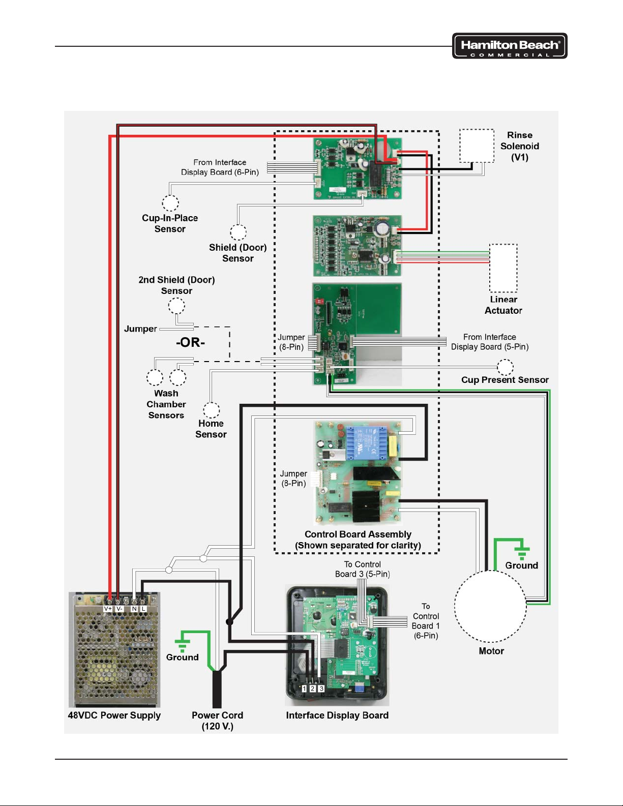
SmartServe™ Drink Mixers Service Manual
BIC2000
Troubleshooting
Page 17 of 92 520008300 08/14
Page 18
SmartServe™ Drink Mixers Service Manual
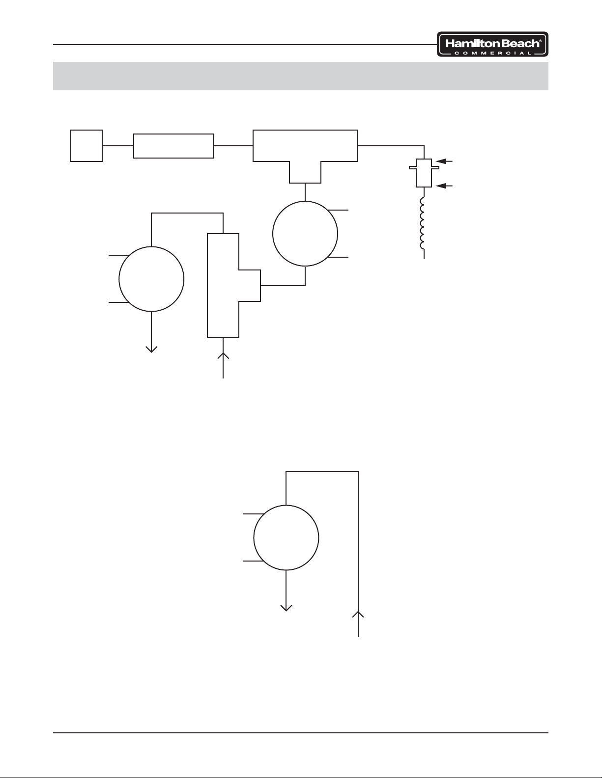
Water and Valve Diagrams
MIC2000
Sanitize
Port
Black 2
White 1
Check Valve
Valve
OUT
To Wash
Chamber
Stem Tee
1/4” OD TUBE
3/16” OD TUBE
4 Black
Valve
3 White
Water
Delivery
to Cup
WATER INLET
BIC2000
Black 2
White 1
Valve
OUT
To Wash
Chamber
WATER INLET
Troubleshooting
Page 18 of 92 520008300 08/14
Page 19
SmartServe™ Drink Mixers Service Manual
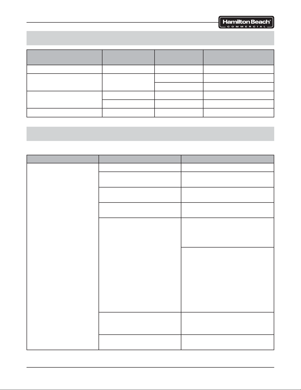
Component Testing
COMPONENT OPERATING
VOLTAGE
Motor 85 VDC 4.4 Ω WHT to BLK
Linear Actuator 48 VDC 2.7 Ω RED/WHT to RED
Power Supply 120 VAC N/A L to N
48 VDC N/A V- to V+
Water Solenoid Valve 24 VDC 92 Ω at valve
RESISTANCE
(Approximate)
2.7 Ω GRN/WHT to GRN
TEST
LOCATION
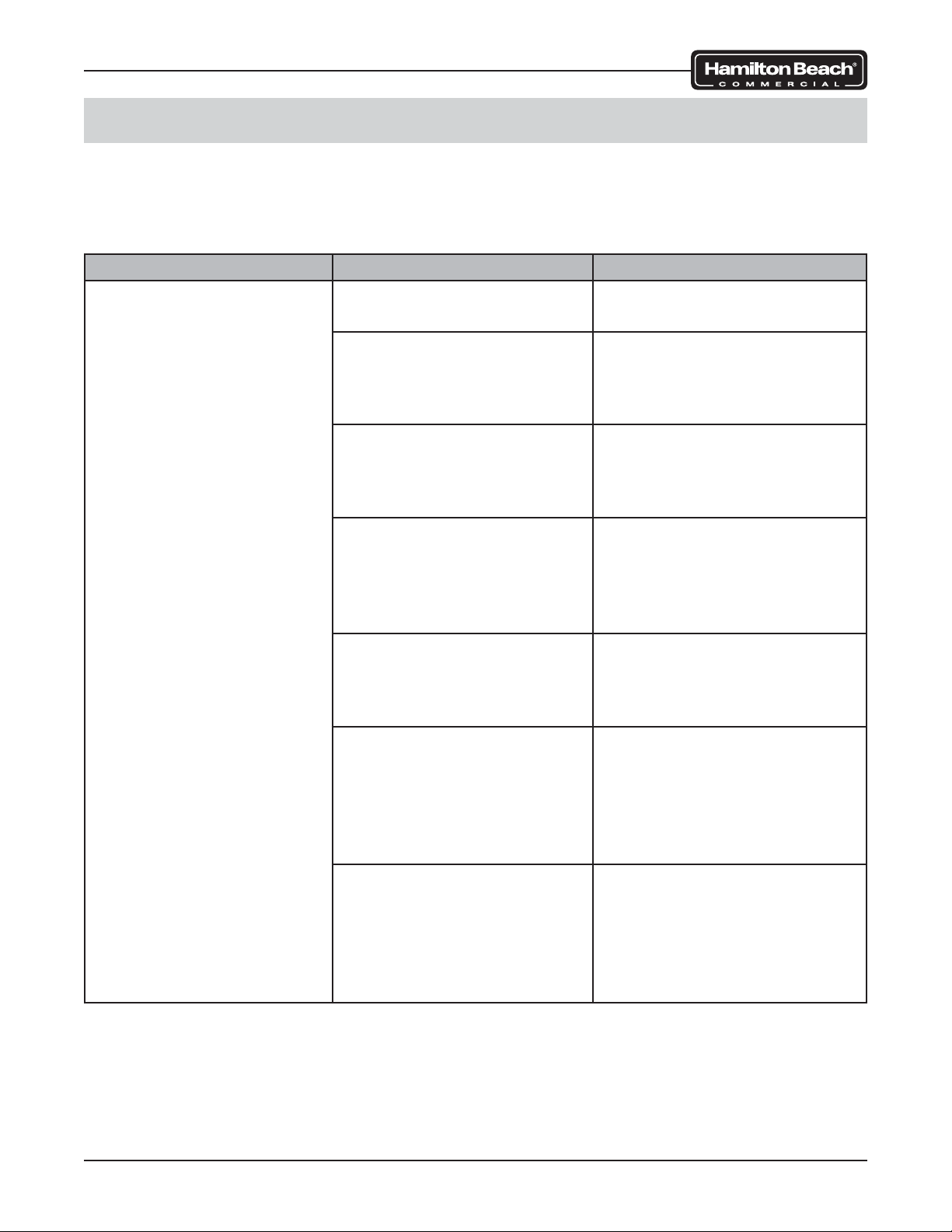
Troubleshooting Guide
If SmartServe™ is not operating properly, identify the problem and use the tables below:
SYMPTOM POSSIBLE CAUSE CORRECTIVE ACTION
Product too thick after
blending (MIC Only)
Water is turned off Turn water on.
Not enough water pressure
(less than 45 psi)
Obstruction in water supply
line
Clogged water fi lter (if ap-
plicable)
Improperly calibrated water Use operator interface panel to
Product is too cold or being
stored at incorrect temperature
Water solenoid valve malfunction (stuck closed)
Ensure location has
suffi cient water pressure.
Repair kinks or replace line.
Check in-store water
fi ltration system.
check WATER SCALE percentage. Record reading. Contact
Technical Services.
Check if SmartServe™ is using
factory settings or if customized
settings were implemented via
USB port during installation. If
factory settings are being used,
contact sales
representative to have
SmartServe™ custom-programmed.
Check temperature of freezer
unit. Adjust as necessary.
Test water solenoid valve. Replace as necessary.
Troubleshooting
Page 19 of 92 520008300 08/14
Page 20
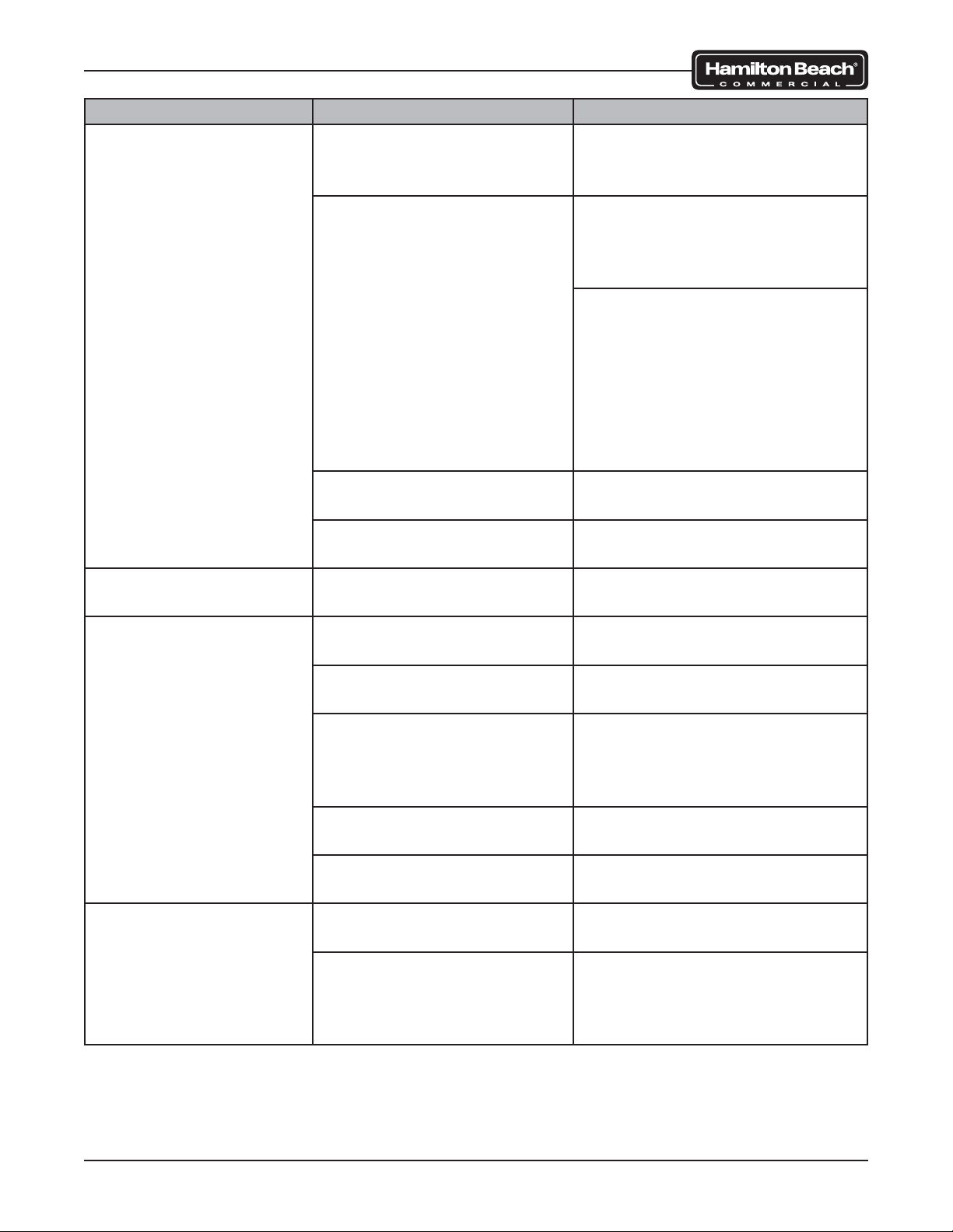
SmartServe™ Drink Mixers Service Manual
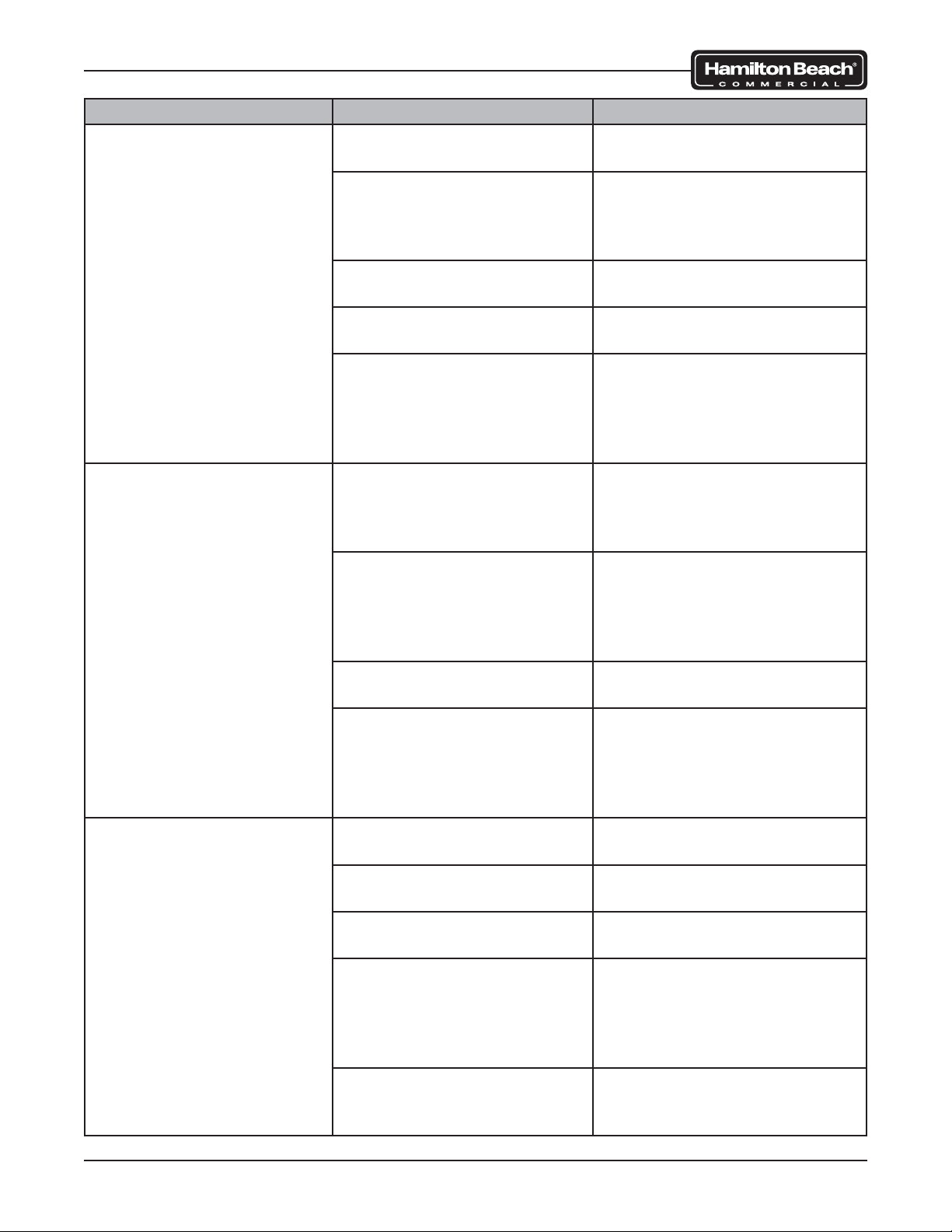
SYMPTOM POSSIBLE CAUSE CORRECTIVE ACTION
Product too thin after
blending (MIC Only)
Product is too warm or
being stored at incorrect
temperature
Improperly calibrated water Use operator interface panel to
Hot water is being used for
water supply
Water solenoid valve
malfunction (stuck open)
Cup holder is loose or
Failed cup holder Replace cup holder.
missing
Water leaking from bot-
tom of SmartServe™
Loose or damaged water
lines
Leaking water solenoid
valve
Leaking water delivery
manifold assembly (MIC
only)
Leaking drain line or fi tting Replace drain line(s) and
SmartServe™ isn’t level Ensure SmartServe™ is mount-
Water leaking from top
of SmartServe™ (MIC
only)
Leaking water delivery coil
tube
Leaking water delivery
manifold assembly (MIC
only)
Check temperature of freezer
unit. Adjust as necessary.
check WATER SCALE percentage. Record reading. Contact
Technical Services.
Check if SmartServe™ is using
factory settings or if customized
settings were implemented via
USB port during installation. If
factory settings are being used,
contact sales representative to
have SmartServe™ customprogrammed.
Ensure water supply is connected to cold water.
Test water solenoid valve. Replace as necessary.
Repair or replace water lines.
Replace water solenoid valve.
Replace water delivery manifold
assembly. Check boards for
signs of shorting because the
boards probably got wet.
fi tting(s) as necessary.
ed on a level surface.
Repair loose connection or re-
place water delivery coil tube.
Replace water delivery manifold
assembly. Check boards for
signs of shorting because the
boards probably got wet.
Troubleshooting
Page 20 of 92 520008300 08/14
Page 21
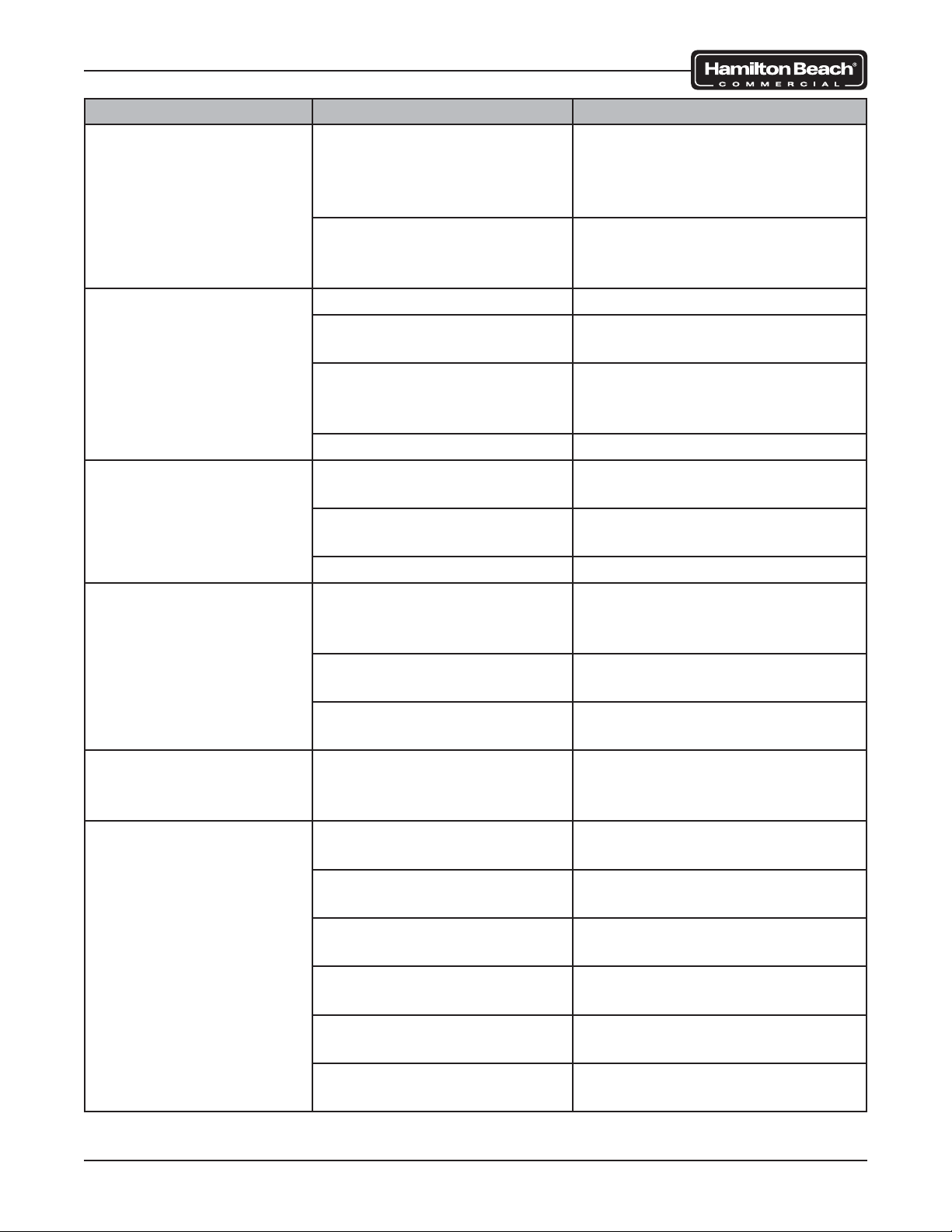
SmartServe™ Drink Mixers Service Manual
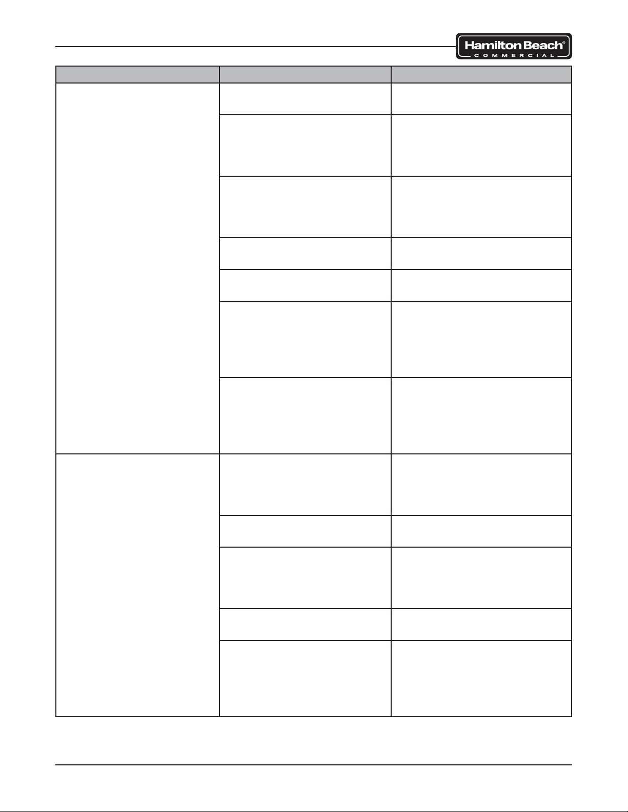
SYMPTOM POSSIBLE CAUSE CORRECTIVE ACTION
Clicking noise at start of
blend cycle
Stepper motor lead screw
needs lubrication
Water delivery coil tube
cover getting caught while
moving down (MIC only)
Smell coming from
SmartServe™
Wash cycle wasn’t initiated Run wash cycle.
Sanitize cycle wasn’t initi-
ated
SmartServe™ and sur-
rounding area requires
cleaning
Obstructed drain line Clear drain line.
Buttons on touch pad
do not work
Loose connection at user
interface display
Loose connection at control
board
Failed touch pad Replace touch pad.
Wash chamber fi lling up
Obstructed drain line Clear drain line. Check drain
with water during rinse
and/or fl ush cycles
Too much soap suds in
wash chamber
SmartServe™ isn’t level Ensure SmartServe™ is mount-
Flashing lights inside
Normal operation No corrective action necessary.
SmartServe™ on control board
SmartServe™ not rins-
Auto-rinse disabled Enable auto-rinse using user
ing
Obstruction inside safety
shield
Loose connection on control
board
Not enough water pressure
(less than 45 psi)
SmartServe™ needs to be
rebooted
Rinse valve not operable Diagnose and replace rinse
Apply lubricant to stepper motor lead screw. Linear actuator
slides should only be cleaned,
never lubricated.
Reroute or move coil tube and
cover as necessary.
Run sanitize cycle.
Clean around and under machine.
Check connections at user interface display.
Check connections at control
board.
line to ensure it is pitched and
vented correctly, if applicable.
Use less soap.
ed on a level surface.
interface display.
Ensure there are no obstruc-
tions inside safety shield.
Ensure there are no loose con-
nections on control board.
Ensure location has suffi cient
water pressure.
Power down SmartServe™ and
turn back on.
valve as required.
Troubleshooting
Page 21 of 92 520008300 08/14
Page 22
SmartServe™ Drink Mixers Service Manual
Error Code Troubleshooting
If Operator Interface Panel displays an error code message, press STOP button repeatedly
until error code message clears or power down SmartServe™ and turn back on to reboot. If
error code message remains, use the table below:
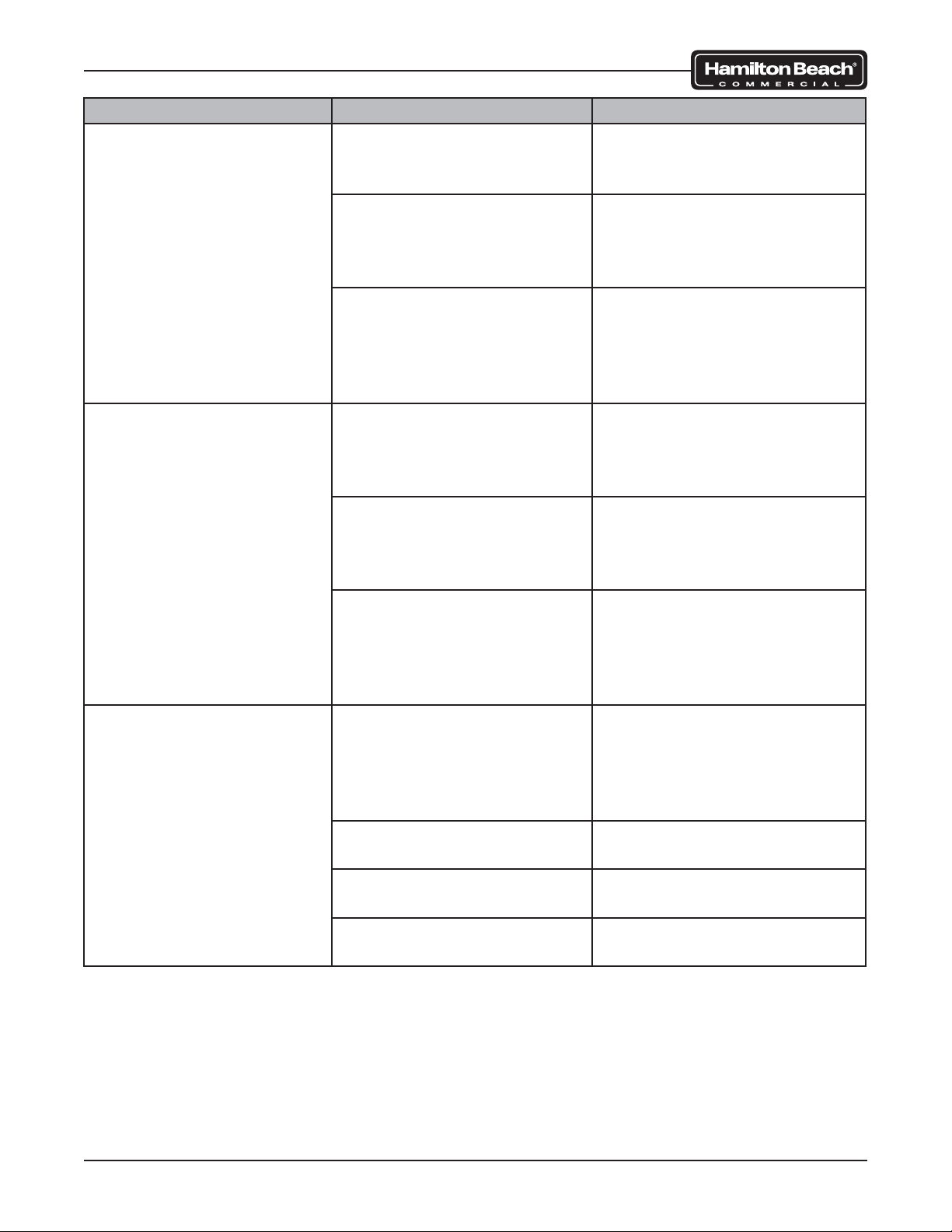
ERROR CODE MESSAGE POSSIBLE CAUSE CORRECTIVE ACTION
U-Interface Error Shake cup not in place Ensure shake cup is placed
inside cup holder properly.
Obstruction in safety shield Ensure there are no obstruc-
tions inside safety shield preventing machine from rinsing
or fl ushing.
Disrupted blend, rinse,
fl ush, wash, or sanitize
cycles.
SmartServe™ needs to be
rebooted
Loose connection or failed
shield sensor
Power supply problem Check power supply connec-
Loose or missing shield
magnet in base of door
Ensure there were no disruptions during blend, rinse,
fl ush, wash, or sanitize cycles.
Press STOP button repeatedly until error code messages clear or power down
SmartServe™ and turn back
on to reboot.
Check connection on shield
sensor. Test shield sensor if
connection is good. Repair or
replace as necessary.
tions. Check voltage at power
supply. Check harness between power supply and control board. Repair or replace
as necessary.
Repair or replace door assembly as required.
Troubleshooting
Page 22 of 92 520008300 08/14
Page 23
SmartServe™ Drink Mixers Service Manual
ERROR CODE MESSAGE POSSIBLE CAUSE CORRECTIVE ACTION
Motor Control Error Shake cup not in place Ensure shake cup is placed
inside cup holder properly.
Obstruction in safety shield Ensure there are no obstruc-
tions inside safety shield preventing machine from rinsing
or fl ushing.
Loose connection at user
interface display
Loose connection at control
board
SmartServe™ needs to be
rebooted
Check connections at user
interface display.
Check connections at control
board.
Press STOP button repeatedly until error code messages clear or power down
SmartServe™ and turn back
on to reboot.
Motor Control Error
Stepper Motion Error
Loose connection or failed
home sensor
Check connection on home
sensor. Test home sensor if
connection is good. Repair or
replace as necessary.
Loose connection or failed
cup present sensor
Check connection on cup
present sensor. Test cup
present sensor if connection
is good. Repair or replace as
necessary.
Failed control board Test control board. Replace as
necessary.
SmartServe™ needs to be
rebooted
Press STOP button repeatedly until error code messages clear or power down
SmartServe™ and turn back
on to reboot.
Motor Control Error
Hall Sensor
Loose connection at control
board
Check connections at control
board.
Failed motor Test motor. Replace as neces-
sary.
Failed control board Test control board. Replace as
necessary.
SmartServe™ needs to be
rebooted
Press STOP button repeatedly until error code messages clear or power down
SmartServe™ and turn back
on to reboot.
Program ramp rate confl ict Contact sales to supply or
verify any new custom program.
Troubleshooting
Page 23 of 92 520008300 08/14
Page 24
SmartServe™ Drink Mixers Service Manual
ERROR CODE MESSAGE POSSIBLE CAUSE CORRECTIVE ACTION
Communication Error Shake cup not in place Ensure shake cup is placed
inside cup holder properly.
Disrupted blend, rinse,
fl ush, wash, or sanitize
cycles.
Ensure there were no disruptions during blend, rinse,
fl ush, wash, or sanitize cycles.
Lower cup shield is assembled improperly or not
installed on cup guard housing properly
Loose connection at user
interface display
Loose connection at control
board
Loose connection or failed
wash chamber sensor
Ensure lower cup shield is
assembled correctly and installed on cup guard housing
properly. Magnets go to rear.
Check connections at user
interface display.
Check connections at control
board.
Check connection on wash
chamber sensor. Test wash
chamber sensor if connection
is good. Repair or replace as
necessary.
SmartServe™ needs to be
rebooted
Press STOP button repeatedly until error code messages clear or power down
SmartServe™ and turn back
on to reboot.
Shield Obstruction Error Obstruction in safety shield Ensure there are no obstruc-
tions inside safety shield preventing machine from rinsing
or fl ushing.
Shake cup not in place Ensure shake cup is placed
inside cup holder properly.
Lower cup shield is assembled improperly or not
installed on cup guard housing properly
Loose connection at control
board
SmartServe™ needs to be
rebooted
Ensure lower cup shield is
assembled correctly and installed on cup guard housing
properly. Magnets go to rear.
Check connections at control
board.
Press STOP button repeatedly until error code messages clear or power down
SmartServe™ and turn back
on to reboot.
Troubleshooting
Page 24 of 92 520008300 08/14
Page 25
SmartServe™ Drink Mixers Service Manual
ERROR CODE MESSAGE POSSIBLE CAUSE CORRECTIVE ACTION
Interlock Error Product is too cold or being
stored at incorrect tempera-
Check temperature of freezer
unit. Adjust as necessary.
ture
Obstruction in safety shield Ensure there are no obstruc-
tions inside safety shield preventing machine from rinsing
or fl ushing.
SmartServe™ needs to be
rebooted
Press STOP button repeatedly until error code messages clear or power down
SmartServe™ and turn back
on to reboot.
Replace Cup Cup sensor is disabled Use operator interface panel
to see if cup sensor is enabled. If disabled, set to
enabled.
Loose connection or failed
cup sensor
Check connection on control board. Test cup sensor if
connection is good. Repair or
replace as necessary.
SmartServe™ needs to be
rebooted
Press STOP button repeatedly until error code messages clear or power down
SmartServe™ and turn back
on to reboot.
Hamilton Beach
Commercial (screen froze,
touch pad doesn’t work)
SmartServe™ needs to be
rebooted
Press STOP button repeatedly until error code messages clear or power down
SmartServe™ and turn back
on to reboot.
Failed linear actuator Test linear actuator. Replace
as necessary.
Failed motor Test motor. Replace as nec-
essary.
Failed touch pad Test touch pad. Replace as
necessary.
Troubleshooting
Page 25 of 92 520008300 08/14
Page 26
SmartServe™ Drink Mixers Service Manual
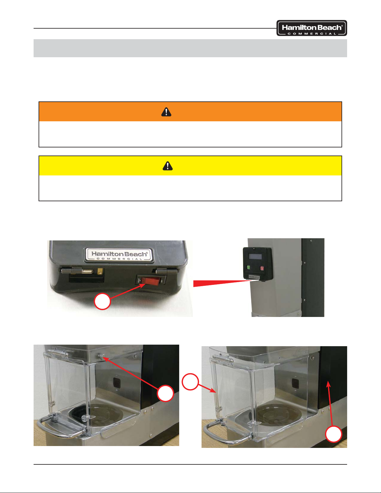
Safety Shield Assembly
The safety shield assembly is located on the front of the machine. The assembly includes a
shield door that can be serviced separately. A magnet embedded in the assembly interacts with
the shield sensor. Some models have two door magnets and sensors. The machine will not
operate if the safety shield assembly is not installed and the door is not closed properly.
WARNING
To avoid risk of serious injury or death, disconnect power to the machine before
cleaning, servicing, or removing parts.
CAUTION
Do not use power tools to remove hardware. Damage to the hardware or the machine
may occur. Do not lose hardware.
To remove the safety shield assembly:
1. Ensure the control panel power switch (1) is in the OFF position and unplug the
machine.
1
2. Remove two thumb screws (2) from the safety shield assembly (3).
3. Slide the safety shield assembly (3) forward to remove from the machine (4).
3
Removal and Replacement
2
4
Page 26 of 92 520008300 08/14
Page 27
SmartServe™ Drink Mixers Service Manual
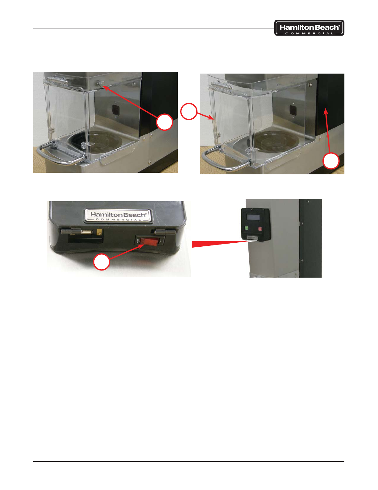
To install the safety shield assembly:
1. Slide the safety shield assembly (3) onto the machine (4).
2. Install a thumb screw (2) on each side of the safety shield assembly (3).
3
2
3. Plug in the power cord to the machine, turn the control panel power switch (1) to the
RESET position, and verify machine operates.
4
1
Removal and Replacement
Page 27 of 92 520008300 08/14
Page 28
SmartServe™ Drink Mixers Service Manual
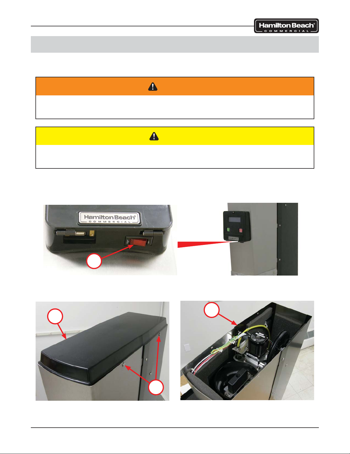
Top Cover
The top cover is located on the top of the machine. Removal of the top cover allows access to
various components of the machine.
WARNING
To avoid risk of serious injury or death, disconnect power to the machine before
cleaning, servicing, or removing parts.
CAUTION
Do not use power tools to remove hardware. Damage to the hardware or the machine
may occur. Do not lose hardware.
To remove the top cover:
1. Ensure the control panel power switch (1) is in the OFF position and unplug the
machine.
1
2. Remove two screws (2) from each side of the machine (3).
3. Lift the top cover (4) from the machine (3).
3
4
Removal and Replacement
2
Page 28 of 92 520008300 08/14
Page 29

SmartServe™ Drink Mixers Service Manual
To install the top cover:
1. Place the top cover (4) onto the machine (3) as shown.
2. Install two screws (2) on each side of the machine (3).
3
4
2
3. Plug in the power cord to the machine, turn the control panel power switch (1) to the
RESET position, and verify machine operates.
1
Removal and Replacement
Page 29 of 92 520008300 08/14
Page 30

SmartServe™ Drink Mixers Service Manual
Operator Interface Panel Assembly
The operator interface panel assembly is located on the front of the machine and is used
to operate the machine. The assembly has a breaker switch, control board, touch pad, and
access door that are serviceable.
WARNING
To avoid risk of serious injury or death, disconnect power to the machine before
cleaning, servicing, or removing parts.
CAUTION
Do not use power tools to remove hardware. Damage to the hardware or the machine
may occur. Do not lose hardware.
To remove the operator interface panel assembly:
1. Ensure the control panel power switch (1) is in the OFF position and unplug the
machine.
2. Lift the metal tab (2) on the panel to lower the access door (3).
2
3
1
Removal and Replacement
Page 30 of 92 520008300 08/14
Page 31

SmartServe™ Drink Mixers Service Manual
3. Remove four screws (4) from the panel (5).
4. Carefully lift the panel (5) from the machine.
5. Mark and disconnect two connectors (6) from the interface control board (7).
6. Mark and disconnect three wires (8) from the breaker switch (9).
5
6
8
4
9
To install the operator interface panel assembly:
1. Ensure the panel gasket (10) is on the machine.
2. Connect three wires (8) to the breaker switch (9).
3. Connect two connectors (6) to the interface control panel (7).
4. Position the panel (5) on the machine and ensure the gasket (10) is seated properly.
5. Install four screws (4) on the panel (5).
6. Close the access door (3).
7
10
7. Plug in the power cord to the machine, turn the control panel power switch (1) to the
RESET position, and verify machine operates.
3
1
Removal and Replacement
Page 31 of 92 520008300 08/14
Page 32

SmartServe™ Drink Mixers Service Manual
Breaker Switch
The breaker switch is located on the operator interface panel and is used to turn the main
power on or off.
To remove the breaker switch:
1. Remove the operator interface panel assembly (1) as outlined in this manual.
2. Depress the tabs (2) on the switch (3) and remove the switch from the operator interface
panel assembly (1).
3
2
1
To install the breaker switch:
1. Push the switch (3) into the operator interface panel assembly (1) until the tabs (2) lock
the switch (3) in place.
2. Install the operator interface panel assembly (1) as outlined in this manual and verify
operation.
Removal and Replacement
Page 32 of 92 520008300 08/14
Page 33

SmartServe™ Drink Mixers Service Manual
Interface Display Board
The interface display board is located on the operator interface panel and is used to display
information to the user and relay input commands to the control board assembly.
To remove the interface display board:
1. Remove the operator interface panel assembly (1) as outlined in this manual.
2. Disconnect the touch pad ribbon cable (2) from the display board (3).
3. Remove eight screws (4) and gently pull upper boards from lower board.
CAUTION
Use care when removing the upper boards from the lower board to avoid damage to
the pins.
4. Remove three screws (5) and lower board from panel.
4
1
3
4
2
To install the interface display board:
1. Separate the display board assembly.
2. Install the lower board with three screws (5) to the operator interface panel
assembly (1).
CAUTION
Use care when installing the upper boards on the lower board to avoid damage to the
pins.
5
3. Gently place the upper boards on the lower board. Ensure the pins line up.
4. Install eight screws (4).
5. Connect the touch pad ribbon cable (2) to the display board (3).
6. Install the operator interface panel assembly (1) as outlined in this manual and verify
operation.
Removal and Replacement
Page 33 of 92 520008300 08/14
Page 34

SmartServe™ Drink Mixers Service Manual
Touch Pad
The touch pad is located on the operator interface panel and is used by the operator to control
the machine.
To remove the touch pad:
1. Remove the operator interface panel assembly (1) as outlined in this manual.
2. Disconnect the touch pad ribbon cable (2) from the display board (3).
3. Using a flat tool, such as a razor, start at the corner and peel the touch pad (4) off the
operator interface panel assembly (1).
4. Pull the ribbon cable (2) through the slot on the operator interface panel assembly (1).
1
4
2 3
To install the touch pad:
1. Clean the surface thoroughly to remove any adhesive residue.
2. Clean the LCD screen to remove any smudges or fingerprints.
3. Insert the ribbon cable (2) through the slot of the operator interface panel assembly (1).
NOTE: The adhesive on the touch pad will adhere to the plastic instantly. It will be very difficult
to reposition the touch pad if not aligned properly. Be careful to avoid air pockets/bubbles. Do
not remove the protective paper all at once.
4. Apply the touch pad (4) starting on the upper left side and slowly roll the protective
paper off the touch pad (4) while applying the touch pad (4) to the panel. Continuously
feed the ribbon cable (2) through the slot.
5. Connect the touch pad ribbon cable (2) to the display board (3).
6. Install the operator interface panel assembly (1) as outlined in this manual and verify
operation.
Removal and Replacement
Page 34 of 92 520008300 08/14
Page 35

SmartServe™ Drink Mixers Service Manual
Cup Guard & Shield Assembly
The cup guard & shield assembly is lowered over the cup during operation and cleaning
cycles. It is mounted on the motor assembly.
To remove the cup guard & shield assembly:
1. Remove the safety shield assembly as outlined in this manual.
2. Remove the top cover as outlined in this manual.
3. Remove the blades using the removal tool (PN 9900167800). The threads are right
hand and it may be necessary to strike the tool with a hammer to loosen the blades.
4. Remove three screws (1) from each side of the machine.
5. Lift the front panel wrap (2) from the machine.
NOTE: Avoid overextending the wire harness attached to the interface panel on the wrap.
NOTE: Cover front panel wrap to avoid scratches/damage from contact with side of machine.
6. Using a large wire tie (3), secure the wrap (2) to the machine using the hole in the top of
the side panel (4).
2
2
1
7. Remove the cup shield (5) by pressing the tab (6) in the cup guard and shield
assembly (7) and turn the cup shield (5) clockwise.
7
3
4
6
ROTATE
Removal and Replacement
5
Page 35 of 92 520008300 08/14
Page 36

SmartServe™ Drink Mixers Service Manual
8. Raise the cup guard and shield assembly (7) and place a support block (8) under the
shield block (9).
9. Remove two flange nuts (10), shield block (9), and cup guard and shield assembly (7)
from the motor assembly (11).
9
8
11
10
7
11
To install the cup guard & shield assembly:
1. Install the cup guard and shield assembly (7) with two flange nuts (10) and shield
block (9) on the motor assembly (11).
NOTE: Take care to align motor shaft with shaft seal so bearing grommet and shaft seal are
not pushed out of place by motor shaft during installation.
2. Install the cup shield (5) on the cup guard and shield assembly (7) until the tab (6) locks
into place.
7
6
5
ROTATE
Removal and Replacement
Page 36 of 92 520008300 08/14
Page 37

SmartServe™ Drink Mixers Service Manual
3. Remove the wire tie (3) holding the wrap (2) to the side panel (4).
4. Position the wrap (2) on the machine and secure the wrap with six screws (1).
NOTE: Ensure the wire harness is positioned in a way to avoid interference with the movement
of the cup guard and shield assembly.
2
2
1
5. Install the blade assembly. It is not necessary to tighten the blades with a tool. The
operation of the machine will tighten the bladed assembly sufficiently.
6. Install the top cover as outlined in this manual.
7. Install the safety shield assembly as outlined in this manual.
8. Plug in the power cord to the machine, turn the control panel power switch to the
RESET position, and verify machine operates.
3
4
Removal and Replacement
Page 37 of 92 520008300 08/14
Page 38

SmartServe™ Drink Mixers Service Manual
Motor Assembly
The motor assembly is used to turn the blade assembly. It receives power through the control
board.
To remove the motor assembly:
NOTE: This removal procedure is for the BIC2000. The removal procedure for the MIC2000
is similar and will require the water supply to be disconnected and the system purged before
removing the motor assembly.
1. Remove the blades using the removal tool (PN 9900167800). The threads are right
hand and it may be necessary to strike the tool with a hammer to loosen the blades.
2. Remove the shield assembly as outlined in this manual.
3. Pull up on the motor cord (1) just under the top pulley (2). This will raise the lower pulley
(3). Position a punch or screwdriver through the hole in the upper portion of the festoon
sheet metal (4) and one of the holes in the lower pulley (3). This will hold the spring
force and create slack in the motor cord (1).
4. Remove two clamps (5) from the motor assembly (6).
3
1
5
6
4
2
5. Mark and disconnect six wires (7).
NOTE: On the MIC2000, disconnect the spiral water line from the water delivery manifold
before step 5.
6. Remove two screws (8) and motor assembly (6) from the linear actuator assembly (9).
8
Ground
9
7
MOTOR
CORD
Removal and Replacement
MOTOR
6
Page 38 of 92 520008300 08/14
Page 39

SmartServe™ Drink Mixers Service Manual
7. Remove four screws (10) and harness cover (11) from motor assembly (6).
8. Pull six wires (7) from the motor assembly (6).
10
11
7
10
6
To install the motor assembly:
1. Feed six wires (7) into the motor assembly (6).
2. Secure the wire harness in place with the harness cover (11) and four screws (10).
3. Install the motor assembly (6) on the linear actuator assembly (9) with two screws (8).
4. Connect six wires (7).
MOTOR
CORD
8
Ground
MOTOR
9
7
6
Removal and Replacement
Page 39 of 92 520008300 08/14
Page 40

SmartServe™ Drink Mixers Service Manual
5. Secure the wires (7) with two clamps (5) on the motor assembly (6).
NOTE: On the MIC2000, connect the spiral water line to the water delivery manifold after
step 5.
6. Pull up on the motor cord (1) just under the top pulley (2). This will raise the lower pulley
(3). Remove the punch or screwdriver holding the lower pulley (3) and gently lower the
motor cord (1) into place.
3
1
5
6
4
2
7. Install the shield assembly as outlined in this manual.
8. Install the blade assembly. It is not necessary to tighten the blades with a tool. The
operation of the machine will tighten the bladed assembly sufficiently.
9. Plug in the power cord to the machine, turn the control panel power switch to the
RESET position, and verify machine operates.
Removal and Replacement
Page 40 of 92 520008300 08/14
Page 41

SmartServe™ Drink Mixers Service Manual
Linear Actuator Assembly
The linear actuator assembly is used to lower and raise the motor carriage during use.
To remove the linear actuator assembly:
1. Remove the safety shield assembly as outlined in this manual.
2. Remove the top cover as outlined in this manual.
3. Remove three screws (1) from each side of the machine.
4. Lift the front panel wrap (2) from the machine.
NOTE: Avoid overextending the wire harness attached to the interface panel on the wrap.
NOTE: Cover front panel wrap to avoid scratches/damage from contact with side of machine.
5. Using a large wire tie (3), secure the wrap (2) to the machine using the hole in the top of
the side panel (4).
2
2
1
6. Remove six screws (5) and back cover (6) from machine.
NOTE: Remove any wire ties as required.
7. Remove four nuts (7) and lockwashers (8) from control board (9).
8. Position the control board (9) to the left to access and disconnect the linear motor
connector (10).
3
4
7
5
9
6
5
Removal and Replacement
9
8
Page 41 of 92 520008300 08/14
10
Page 42

SmartServe™ Drink Mixers Service Manual
NOTE: On the MIC2000, disconnect the spiral water line from the water delivery manifold
before step 9.
9. Remove two screws (11) and lift motor assembly (12) from the linear motor assembly
(13). Allow the motor assembly to hang by the motor cord.
10. Position the motor mount (14) so that all eight screws (15) are accessible.
11. Remove eight screws (15) and linear motor assembly (13) from machine.
NOTE: Motor shown removed for clarity.
11
13
15
15
14
12
15
15
13
To install the linear actuator assembly:
1. Install the linear motor assembly (13) on the machine with eight screws (15).
2. Place the motor assembly (12) on the linear motor assembly (13) and secure in place
with two screws (11).
Removal and Replacement
Page 42 of 92 520008300 08/14
Page 43

SmartServe™ Drink Mixers Service Manual
NOTE: On the MIC2000, connect the spiral water line to the water delivery manifold after
step 2.
3. Connect the linear motor connector (10) to the control board (9).
4. Position the control board (9) on the standoffs and install lockwashers (8) and nuts (7).
NOTE: Secure any loose wires with wire ties as required.
5. Install six screws (5) and back cover (6) on the machine.
7
5
9
6
5
9
10
8
6. Remove the wire tie (3) holding the wrap (2) to the side panel (4).
7. Position the wrap (2) on the machine and secure the wrap with six screws (1).
NOTE: Ensure the wire harness is positioned in a way to avoid interference with the movement
of the cup guard and shield assembly.
2
2
3
1
8. Install the top cover as outlined in this manual.
9. Install the safety shield assembly as outlined in this manual.
10. Plug in the power cord to the machine, turn the control panel power switch to the
RESET position, and verify machine operates.
Removal and Replacement
Page 43 of 92 520008300 08/14
4
Page 44

SmartServe™ Drink Mixers Service Manual
48VDC Power Supply
The 48VDC power supply is located behind the back panel and distributes power to control
board #1 and jumps to control board #2 to supply power for valves and linear actuator motor.
WARNING
To avoid risk of serious injury or death, disconnect power to the machine before
cleaning, servicing, or removing parts.
CAUTION
Do not use power tools to remove hardware. Damage to the hardware or the machine
may occur. Do not lose hardware.
To remove the power supply:
1. Ensure the control panel power switch (1) is in the OFF position and unplug the
machine.
1
2. Remove six screws (2) and back cover (3) from machine.
NOTE: Remove any wire ties as required.
3. Loosen four knobs (4). Do not remove the knobs.
2
Removal and Replacement
4
4
3
2
Page 44 of 92 520008300 08/14
Page 45

SmartServe™ Drink Mixers Service Manual
4. Lift and rotate clockwise the power control assembly (5) until you are able to access the
rear of the power control assembly (5).
5. Mark and disconnect four wires (6) from the power supply (7).
6. Remove four screws (8), washers (9), and power supply (7) from the power control
assembly (5).
V+
(Red)
V-
(Black/Red)
N
(White)
L
(Black)
5
7 8
6
7
9
7. Remove four screws (10) and power supply (7) from the isolation panel (11).
7
11
10
To install the power supply:
1. Install four screws (10) and power supply (7) on the isolation panel (11).
2. Install the power supply (7) on the power control assembly (5) with four washers (9) and
screws (8).
3. Connect four wires (6) to the power supply (7).
Removal and Replacement
Page 45 of 92 520008300 08/14
Page 46

SmartServe™ Drink Mixers Service Manual
4. Carefully position the power control assembly (5) on the four knobs (4).
NOTE: Ensure all connections on the power supply and control board are secure. Replace any
wire ties as required.
5. Hand-tighten the four knobs (4).
6. Install the back cover (3) with six screws (2).
2
4
4
3
2
7. Plug in the power cord to the machine, turn the control panel power switch (1) to the
RESET position, and verify machine operates.
1
Removal and Replacement
Page 46 of 92 520008300 08/14
Page 47

SmartServe™ Drink Mixers Service Manual
Control Board Assembly
The control board assembly is located behind the back panel and controls all functions of the
machine.
WARNING
To avoid risk of serious injury or death, disconnect power to the machine before
cleaning, servicing, or removing parts.
CAUTION
Do not use power tools to remove hardware. Damage to the hardware or the machine
may occur. Do not lose hardware.
To remove the control board assembly:
1. Ensure the control panel power switch (1) is in the OFF position and unplug the
machine.
1
2. Remove six screws (2) and back cover (3) from machine.
NOTE: Remove any wire ties as required.
3. Loosen four knobs (4). Do not remove the knobs.
2
Removal and Replacement
4
4
3
2
Page 47 of 92 520008300 08/14
Page 48

SmartServe™ Drink Mixers Service Manual
4. Remove four nuts (5) and lockwashers (6) from control board (7).
5. Position the control board (7) to the left to access and disconnect the linear motor
connector (8).
6. Position the control board (7) on the standoffs (9) and install lockwashers (6) and
nuts (5).
5
7
7
6
7. Lift and rotate clockwise the power control assembly (10) until you are able to access
the rear of the power control assembly (10).
8. Mark and disconnect all wires (11) and connectors (12) from the control board (7).
9. Remove four screws (13) and control board (7) from the power control assembly (10).
12
11
7
8
9
13
12
12
To install the control board assembly:
1. Install the control board (7) on the power control assembly (10) with four screws (13).
2. Connect all wires (11) and connectors (12) to the correct location on control board (7).
Removal and Replacement
11
Page 48 of 92 520008300 08/14
10
Page 49

SmartServe™ Drink Mixers Service Manual
3. Remove four nuts (5) and lockwashers (6) from control board (7).
4. Position the control board (7) to the left to connect the linear motor connector (8).
5. Position the control board (7) on the standoffs (9) and install lockwashers (6) and
nuts (5).
5
7
7
6
6. Carefully position the power control assembly (10) on the four knobs (4).
NOTE: Ensure all connections on the power supply and control board are secure. Replace any
wire ties as required.
7. Hand-tighten the four knobs (4).
8. Install the back cover (3) with six screws (2).
8
9
2
4
4
3
2
9. Plug in the power cord to the machine, turn the control panel power switch (1) to the
RESET position, and verify machine operates.
1
Removal and Replacement
Page 49 of 92 520008300 08/14
Page 50

SmartServe™ Drink Mixers Service Manual
Sensor Assembly (Home Position)
The sensor assembly (home position) is located on the frame near the top of the machine. The
sensor determines the highest position of the motor and cup guard/shield assembly.
To remove the sensor assembly (home position):
1. Remove the top cover as outlined in this manual.
2. Remove six screws (1) and back cover (2) from machine.
NOTE: Remove any wire ties as required. Note the routing of the sensor wiring being replaced.
3. Disconnect sensor connector (3) from control board (4).
1
4
2
3
1
4. Use a screwdriver to depress the tabs on the side of the sensor assembly (5) and
push the sensor assembly (5) through the hole in the frame (6) and remove the sensor
assembly (5). The black plastic housing is part of the sensor assembly.
6
Removal and Replacement
5
PUSH THROUGH
Page 50 of 92 520008300 08/14
Page 51

SmartServe™ Drink Mixers Service Manual
To install the sensor assembly (home position):
1. Push the sensor assembly (5) into the hole in the frame (6).
6
5
NOTE: Route the wire harness for the sensor to the control board in a way that will avoid any
chance of pinching or fraying of the wires. Replace any wire ties as required.
2. Connect sensor connector (3) to the control board (4).
3. Install the back cover (2) with six screws (1).
4
1
2
3
1
4. Install the top cover as outlined in this manual.
5. Plug in the power cord to the machine, turn the control panel power switch to the
RESET position, and verify machine operates.
Removal and Replacement
Page 51 of 92 520008300 08/14
Page 52

SmartServe™ Drink Mixers Service Manual
Sensor Assembly (Cup Present)
The sensor assembly (cup present) is located on the frame near the motor assembly. The
sensor determines the lowest position of the motor and cup guard/shield assembly.
To remove the Sensor Assembly (Cup Present):
1. Remove the safety shield assembly as outlined in this manual.
2. Remove the top cover as outlined in this manual.
3. Remove three screws (1) from each side of the machine.
4. Lift the front panel wrap (2) from the machine.
NOTE: Avoid overextending the wire harness attached to the interface panel on the wrap.
NOTE: Cover front panel wrap to avoid scratches/damage from contact with side of machine.
5. Using a large wire tie (3), secure the wrap (2) to the machine using the hole in the top of
the side panel (4).
2
2
1
6. Remove six screws (5) and back cover (6) from machine.
NOTE: Remove any wire ties as required. Note the routing of the sensor wiring being replaced.
7. Disconnect sensor connector (7) from control board (8).
5
3
4
8
5
Removal and Replacement
6
Page 52 of 92 520008300 08/14
7
Page 53

SmartServe™ Drink Mixers Service Manual
8. Use a screwdriver to depress the tabs on the side of the sensor assembly (9) and push
the sensor assembly (9) through the hole in the frame (10) and remove the sensor
assembly (9). The black plastic housing is part of the sensor assembly.
9
10
To install the sensor assembly (cup present):
1. Push the sensor assembly (9) into the hole in the frame (10).
NOTE: Route the wire harness for the sensor to the control board in a way that will avoid any
chance of pinching or fraying of the wires. Replace any wire ties as required.
2. Connect sensor connector (7) to the control board (8).
3. Install the back cover (6) with six screws (5).
5
6
7
8
5
Removal and Replacement
Page 53 of 92 520008300 08/14
Page 54

SmartServe™ Drink Mixers Service Manual
4. Remove the wire tie (3) holding the wrap (2) to the side panel (4).
5. Position the wrap (2) on the machine and secure the wrap (2) with six screws (1).
NOTE: Ensure the wire harness is positioned in a way to avoid interference with the movement
of the cup guard and shield assembly.
2
2
1
6. Install the top cover as outlined in this manual.
7. Install the safety shield assembly as outlined in this manual.
8. Plug in the power cord to the machine, turn the control panel power switch to the
RESET position, and verify machine operates.
3
4
Removal and Replacement
Page 54 of 92 520008300 08/14
Page 55

SmartServe™ Drink Mixers Service Manual
Cup-In-Place Sensor (Infrared)
The cup-in-place sensor is located on the front of the machine in the mixing chamber.
To remove the cup-in-place sensor:
1. Remove the safety shield assembly as outlined in this manual.
2. Remove the top cover as outlined in this manual.
3. Remove three screws (1) from each side of the machine.
4. Lift the front panel wrap (2) from the machine.
NOTE: Avoid overextending the wire harness attached to the interface panel on the wrap.
NOTE: Cover front panel wrap to avoid scratches/damage from contact with side of machine.
5. Using a large wire tie (3), secure the wrap (2) to the machine using the hole in the top of
the side panel (4).
2
2
1
6. Raise the cup guard and shield assembly (5) and place a support block (6) under the
shield block (7).
3
4
7
6
Removal and Replacement
5
Page 55 of 92 520008300 08/14
Page 56

SmartServe™ Drink Mixers Service Manual
7. Remove two screws (8), washer (9), and plastic spacers (10).
8. Remove two screws (11) from the top of the wash chamber cover (12).
9. Remove six screws (13) from each side of the wash chamber cover (12).
10. Remove two screws (14) from the back of the machine.
13
11
12
13
8 9 10
14
11. Remove six screws (15) and back cover (16) from machine.
NOTE: Remove any wire ties as required. Note the routing of the sensor wiring being replaced.
12. Disconnect sensor connector (17) from control board (18).
15
18
16
17
15
Removal and Replacement
Page 56 of 92 520008300 08/14
Page 57

SmartServe™ Drink Mixers Service Manual
13. Grasp both sides of the wash chamber cover (12) and gently pull the ends away from
the machine.
NOTE: Cover back sides of wash chamber cover to avoid scratches/damage to side of
machine.
14. Slide the wash chamber cover (12) forward to access the sensor (19).
15. Remove two screws (20) and sensor (19) from the wash chamber cover (12).
19
20
12
12
To install the cup-in-place sensor:
1. Install the sensor (19) on the wash chamber cover (12) with two screws (20).
2. Slide the wash chamber cover (12) onto the machine and make sure the tab ends wrap
around the back of the machine.
NOTE: Use food grade grease to ease the wash chamber cover back onto machine. Cover
back sides of wash chamber cover to avoid scratches/damage to side of machine.
NOTE: Route the wire harness for the sensor to the control board in a way that will avoid any
chance of pinching or fraying of the wires. Replace any wire ties as required.
3. Connect sensor connector (17) to the control board (18).
4. Install the back cover (16) with six screws (15).
15
16
17
15
Removal and Replacement
Page 57 of 92 520008300 08/14
18
Page 58

SmartServe™ Drink Mixers Service Manual
5. Install two screws (8), washers (9), and plastic spacers (10) on the wash chamber
cover (12).
6. Install two screws (11) on the top of the wash chamber cover (12).
7. Install six screws (13) on each side of the wash chamber cover (12).
8. Install two screws (14) on the back of the machine.
11
13
12
13
8 9 10
14
9. Raise the cup guard and shield assembly (5) and remove the support block (6) from
under the shield block (7).
7
6
5
Removal and Replacement
Page 58 of 92 520008300 08/14
Page 59

SmartServe™ Drink Mixers Service Manual
10. Remove the wire tie (3) holding the wrap (2) to the side panel (4).
11. Position the wrap (2) on the machine and secure the wrap with six screws (1).
NOTE: Ensure the wire harness is positioned in a way to avoid interference with the movement
of the cup guard and shield assembly.
2
2
1
12. Install the top cover as outlined in this manual.
13. Install the safety shield assembly as outlined in this manual.
14. Plug in the power cord to the machine, turn the control panel power switch to the
RESET position, and verify machine operates.
3
4
Removal and Replacement
Page 59 of 92 520008300 08/14
Page 60

SmartServe™ Drink Mixers Service Manual
Shield Door Sensor
The shield door sensor is located under the wash chamber area. A magnet in the safety
shield assembly interacts with the sensor and requires that the door be closed in order for the
machine to operate. Some models may have two shield door sensors, one on each side of the
door assembly.
To remove the shield door sensor:
1. Remove the safety shield assembly as outlined in this manual.
2. Remove the top cover as outlined in this manual.
3. Remove three screws (1) from each side of the machine.
4. Lift the front panel wrap (2) from the machine.
NOTE: Avoid overextending the wire harness attached to the interface panel on the wrap.
NOTE: Cover front panel wrap to avoid scratches/damage from contact with side of machine.
5. Using a large wire tie (3), secure the wrap (2) to the machine using the hole in the top of
the side panel (4).
2
2
1
6. Remove the cup shield (5) by pressing the tab (6) in the cup guard and shield
assembly (7) and turn the cup shield (5) clockwise.
7
3
4
6
Removal and Replacement
5
Page 60 of 92 520008300 08/14
Page 61

SmartServe™ Drink Mixers Service Manual
7. Remove two screws (8), washer (9), and plastic spacers (10).
8. Remove two screws (11) from the top of the wash chamber cover (12).
9. Remove six screws (13) from each side of the wash chamber cover (12).
10. Remove two screws (14) from the back of the machine.
13
11
12
13
8 9 10
14
11. Remove six screws (15) and back cover (16) from machine.
NOTE: Remove any wire ties as required. Note the routing of the sensor wiring being replaced.
12. Disconnect sensor connector (17) from control board (18).
NOTE: See wiring diagram for models with two shield door sensors.
15
18
17
16
15
Removal and Replacement
Page 61 of 92 520008300 08/14
Page 62

SmartServe™ Drink Mixers Service Manual
13. Grasp both sides of the wash chamber cover (12) and gently pull the ends away from
the machine.
NOTE: Cover back sides of wash chamber cover to avoid scratches/damage to side of
machine.
14. Slide the wash chamber cover (12) forward and rotate as shown to access the
sensor (19).
15. Remove two screws (20) and sensor (19) from the wash chamber cover (12).
19
20
12
To install the shield sensor:
1. Install the sensor (19) on the wash chamber cover (12) with two screws (20).
2. Slide the wash chamber cover (12) onto the machine and make sure the tab ends wrap
around the back of the machine.
NOTE: Use food grade grease to ease the wash chamber cover back onto machine. Cover
back sides of wash chamber cover to avoid scratches/damage to side of machine.
NOTE: Route the wire harness for the sensor to the control board in a way that will avoid any
chance of pinching or fraying of the wires. Replace any wire ties as required.
3. Connect sensor connector (17) to the control board (18).
NOTE: See wiring diagram for models with two shield door sensors.
4. Install the back cover (16) with six screws (15).
15
12
18
15
Removal and Replacement
17
16
Page 62 of 92 520008300 08/14
Page 63

SmartServe™ Drink Mixers Service Manual
5. Install two screws (8), washer (9), and plastic spacers (10) on the wash chamber
cover (12).
6. Install two screws (11) on the top of the wash chamber cover (12).
7. Install six screws (13) on each side of the wash chamber cover (12).
8. Install two screws (14) on the back of the machine.
11
13
12
13
8 9 10
14
9. Install the cup shield (5) on the cup guard and shield assembly (7) until the tab (6) locks
into place.
7
6
5
Removal and Replacement
Page 63 of 92 520008300 08/14
Page 64

SmartServe™ Drink Mixers Service Manual
10. Remove the wire tie (3) holding the wrap (2) to the side panel (4).
11. Position the wrap (2) on the machine and secure the wrap with six screws (1).
NOTE: Ensure the wire harness is positioned in a way to avoid interference with the movement
of the cup guard and shield assembly.
2
2
1
12. Install the top cover as outlined in this manual.
13. Install the safety shield assembly as outlined in this manual.
14. Plug in the power cord to the machine, turn the control panel power switch to the
RESET position, and verify machine operates.
3
4
Removal and Replacement
Page 64 of 92 520008300 08/14
Page 65

SmartServe™ Drink Mixers Service Manual
Wash Chamber Assembly
The wash chamber assembly is located under the wash chamber cover.
To remove the wash chamber assembly:
1. Shut off water supply, disconnect water line from machine, and purge the system to
remove water from the lines.
2. Remove the safety shield assembly as outlined in this manual.
3. Remove the top cover as outlined in this manual.
4. Remove three screws (1) from each side of the machine.
5. Lift the front panel wrap (2) from the machine.
NOTE: Avoid overextending the wire harness attached to the interface panel on the wrap.
NOTE: Cover front panel wrap to avoid scratches/damage from contact with side of machine.
6. Using a large wire tie (3), secure the wrap (2) to the machine using the hole in the top of
the side panel (4).
2
2
1
7. Remove the cup shield (5) by pressing the tab (6) in the cup guard and shield
assembly (7) and turn the cup shield (5) clockwise.
7
3
4
6
Removal and Replacement
5
Page 65 of 92 520008300 08/14
Page 66

SmartServe™ Drink Mixers Service Manual
8. Remove two screws (8), washer (9), and plastic spacers (10).
9. Remove two screws (11) from the top of the wash chamber cover (12).
10. Remove six screws (13) from each side of the wash chamber cover (12).
11. Remove two screws (14) from the back of the machine.
13
11
12
13
8 9 10
14
12. Remove six screws (15) and back cover (16) from machine.
NOTE: Remove any wire ties as required. Note the routing of the sensor wiring being replaced.
13. Disconnect two sensor connectors (17) from control board (18).
18
15
16
17
15
Removal and Replacement
Page 66 of 92 520008300 08/14
Page 67

SmartServe™ Drink Mixers Service Manual
14. Grasp both sides of the wash chamber cover (12) and gently pull the ends away from
the machine.
NOTE: Cover back sides of wash chamber cover to avoid scratches/damage to side of
machine.
15. Slide the wash chamber cover (12) forward and rotate as shown.
16. Remove four screws (19) from wash chamber assembly (20).
20
19
12
12
17. Disconnect water line (21) from solenoid (22).
18. Remove the wash chamber assembly (20) from the machine and pull the sensor
harness (23) and water line (21) through the frame cavity.
20
22
21
23
21
To install the wash chamber assembly:
1. Feed the sensor harness (23) and water line (21) through the frame cavity and position
the wash chamber assembly (20) on the frame.
2. Connect water line (21) to the solenoid (22).
3. Install the wash chamber assembly (20) with four screws (19).
4. Slide the wash chamber cover (12) onto the machine and make sure the tab ends wrap
around the back of the machine.
NOTE: Use food grade grease to ease the wash chamber cover back onto machine. Cover
back sides of wash chamber cover to avoid scratches/damage to side of machine.
Removal and Replacement
Page 67 of 92 520008300 08/14
Page 68

SmartServe™ Drink Mixers Service Manual
NOTE: Route the wire harness for the sensor to the control board in a way that will avoid any
chance of pinching or fraying of the wires. Replace any wire ties as required.
5. Connect sensor connector (17) to the control board (18).
6. Install the back cover (16) with six screws (15).
15
18
16
17
15
7. Install two screws (8), washer (9), and plastic spacers (10) on the wash chamber
cover (12).
8. Install two screws (11) on the top of the wash chamber cover (12).
9. Install six screws (13) on each side of the wash chamber cover (12).
10. Install two screws (14) on the back of the machine.
14
13
13
11
12
8 9 10
Removal and Replacement
Page 68 of 92 520008300 08/14
Page 69

SmartServe™ Drink Mixers Service Manual
11. Install the cup shield (5) on the cup guard and shield assembly (7) until the tab (6) locks
into place.
7
6
5
12. Remove the wire tie (3) holding the wrap (2) to the side panel (4).
13. Position the wrap (2) on the machine and secure the wrap with six screws (1).
NOTE: Ensure the wire harness is positioned in a way to avoid interference with the movement
of the cup guard and shield assembly.
2
2
1
14. Install the top cover as outlined in this manual.
15. Install the safety shield assembly as outlined in this manual.
16. Reconnect the main water line to the machine.
17. Plug in the power cord to the machine, turn the control panel power switch to the
RESET position, and verify machine operates.
3
4
Removal and Replacement
Page 69 of 92 520008300 08/14
Page 70

SmartServe™ Drink Mixers Service Manual
Water Solenoid
The MIC2000 has two water solenoids and the BIC2000 only has one water solenoid. The
BIC2000 is the model shown. Removal procedure for both is similar. See the Water and Valve
Diagrams for hose and valve positions.
NOTE: Make note of water flow indicators on solenoid (small arrow on underside of intake
side) and water flow directions on solenoid support (IN, OUT, and REAR stamped into metal to
indicate flow direction and solenoid support orientation) to install new solenoid and water lines
in correctly.
WARNING
To avoid risk of serious injury or death, disconnect power to the machine before
cleaning, servicing, or removing parts.
CAUTION
Do not use power tools to remove hardware. Damage to the hardware or the machine
may occur. Do not lose hardware.
To remove the water solenoid:
1. Shut off water supply, disconnect water line from machine, and purge the system to
remove water from the lines.
2. Ensure the control panel power switch (1) is in the OFF position and unplug the
machine.
1
Removal and Replacement
Page 70 of 92 520008300 08/14
Page 71

SmartServe™ Drink Mixers Service Manual
3. Remove six screws (2) and back cover (3) from machine.
4. Disconnect water line (4) from solenoid (5).
5. Disconnect inlet water line (6) from inlet port (7).
6. Remove two nuts (8), screws (9), and solenoid support (10) from the frame.
NOTE: Remove any wire ties as required.
5
9
8
10
2
3
2
6
4
7. Mark and disconnect two wires (11) from the solenoid (5).
8. Remove two screws (12) and solenoid (5) from solenoid support (10).
11
5
12
To install the water solenoid:
7
5
10
1. Install solenoid (5) on the solenoid support (10) with two screws (12).
2. Connect two wires (11) to the solenoid (5).
NOTE: Replace any wire ties as required.
3. Position the solenoid support (10) on the frame and install two nuts (8) and screws (9).
4. Connect inlet water line (6) to inlet port (7).
5. Connect water line (4) to solenoid (5).
6. Install the back cover (3) with six screws (2).
Removal and Replacement
Page 71 of 92 520008300 08/14
Page 72

SmartServe™ Drink Mixers Service Manual
7. Reconnect the main water line to the machine.
8. Plug in the power cord to the machine, turn the control panel power switch (1) to the
RESET position, and verify machine operates.
1
Wash Chamber Gasket
The wash chamber gasket provides a seal to prevent water from leaking from the wash
chamber.
To replace the wash chamber gasket:
1. Remove the wash chamber assembly as outlined in this manual.
2. Place the wash chamber on a suitable work surface.
3. Remove nine screws (1), screw (2), screw (3), and gasket cover (4) from wash chamber
assembly (5).
4. Remove gasket (6) from gasket cover (4) and wash chamber assembly (5).
NOTE: Ensure all old gasket material is removed before installing a new gasket.
1
1
5
2
6
1
3
4
Removal and Replacement
Page 72 of 92 520008300 08/14
Page 73

SmartServe™ Drink Mixers Service Manual
To install the wash chamber gasket:
NOTE: Ensure all old gasket material is removed before installing a new gasket.
1. Place the gasket (6) on the wash chamber assembly (5).
2. Place the gasket cover (4) on the gasket (6) and wash chamber assembly (5).
3. Install screw (2) and screw (3). DO NOT TIGHTEN.
4. Install nine screws (1). DO NOT TIGHTEN.
5. Using an alternating pattern, tighten screw (2), screw (3), and nine screws (1) to ensure
the gasket (6) is sealed evenly between the gasket cover (4) and wash chamber
assembly (5).
6. Install the wash chamber assembly as outlined in this manual.
1
1
5
2
6
1
3
4
Removal and Replacement
Page 73 of 92 520008300 08/14
Page 74

SmartServe™ Drink Mixers Service Manual
Water Manifold (MIC2000 Only)
The water manifold is located near the top of the machine.
To remove the water manifold:
1. Shut off water supply, disconnect water line from machine, and purge the system to
remove water from the lines.
2. Remove the top cover as outlined in this manual.
3. Disconnect the spiral water line (1) from the manifold (2).
4. Disconnect the supply water line (3) from the manifold (2).
5. Remove two screws (4) and manifold (2) from the frame.
3
4
2
1
To install the water manifold:
1. Install manifold (2) on the frame with two screws (4).
2. Connect the spiral water line (1) to the manifold (2).
3. Connect the supply water line (3) to the manifold (2).
4. Reconnect the main water line to the machine.
5. Install the top cover as outlined in this manual.
6. Plug in the power cord to the machine, turn the control panel power switch to the
RESET position, and verify machine operates.
Removal and Replacement
Page 74 of 92 520008300 08/14
Page 75

SmartServe™ Drink Mixers Service Manual
Cup Shield Gasket
The cup shield gasket is located in the shield assembly.
To replace the cup shield gasket:
1. Remove the shield assembly as outlined in this manual.
2. Place the shield assembly (1) on a suitable work surface.
3. From the top, push the shaft seal (2) through the cup gasket (3).
4. Pull the cup gasket (3) from the shield assembly (1).
2
2
3
1
To install the cup shield gasket:
1. From the bottom, place the cup gasket (3) into the shield assembly (1). Make sure the
cup gasket is seated properly.
2. From the bottom, push the shaft seal (2) through the cup gasket (3). Make sure the
shaft seal is seated properly.
3. Install the shield assembly as outlined in this manual.
4. Plug in the power cord to the machine, turn the control panel power switch to the
RESET position, and verify machine operates.
3
Removal and Replacement
Page 75 of 92 520008300 08/14
Page 76

SmartServe™ Drink Mixers Service Manual
10
11
14
9
8
7
6
5
20
18
12
15
19
13
17
16
4
2
3
1
fig_1_HB
Replacement Parts List
SHIELD DOOR ASSEMBLY & PANELS
Page 76 of 92 520008300 08/14
Page 77

SmartServe™ Drink Mixers Service Manual
SHIELD DOOR ASSEMBLY & PANELS
ITEM # PART NO. NAME OF PART AMT.
1 990167800 Tool – Blade Removal ..........................................................................................................1
2 990172500 Gasket – Base .....................................................................................................................1
3 * Panel – Right Side (Painted)................................................................................................1
4 * Bracket – Hold Down ...........................................................................................................2
5 * Screw ................................................................................................................................AR
6 * Standoff ................................................................................................................................2
7 * Screw ...................................................................................................................................4
8 * Cover – Top ..........................................................................................................................1
9 * Panel – Left Side (Painted) ..................................................................................................1
10 * Screw ................................................................................................................................AR
11 990153230 Front Shield Door Assembly (Includes Item 12)...................................................................1
12 990153240 Door – Shield .......................................................................................................................1
13 990172300 Thumb Screw .......................................................................................................................2
14 * Screw ...................................................................................................................................4
15 * Cover – Wash Chamber ......................................................................................................1
16 * Reinforcement ......................................................................................................................1
17 * Seal – Wash Chamber .........................................................................................................1
18 * Screw ...................................................................................................................................2
19 * Washer .................................................................................................................................2
20 * Grommet (Plastic) ................................................................................................................2
* Reference Fastener Kit, Cladding Assembly, GM43: 990173000
Replacement Parts List
Page 77 of 92 520008300 08/14
Page 78

SmartServe™ Drink Mixers Service Manual
9
5-6
4
2
1
11
8
10
3
7
fig_2_HB
OPERATOR INTERFACE PANEL ASSEMBLY
Replacement Parts List
Page 78 of 92 520008300 08/14
Page 79

SmartServe™ Drink Mixers Service Manual
OPERATOR INTERFACE PANEL ASSEMBLY
ITEM # PART NO. NAME OF PART AMT.
1 990153200 Enclosure – Operator Interface Assembly ...........................................................................1
2 990153290 Display Board – Interface.....................................................................................................1
3 990153280 Switch – Breaker (Control Panel).........................................................................................1
4 990153210 Touch Pad (Generic) ............................................................................................................1
5 990153270 Door – Interface (Generic) ...................................................................................................1
6 990153220 Door – Interface ...................................................................................................................1
7 * Logo .....................................................................................................................................1
8 * Gasket – Operator Interface Assembly ................................................................................1
9 * Housing – Operator Interface...............................................................................................1
10 * Front Panel Wrap (Stainless Steel) ......................................................................................1
11 * Screw ...................................................................................................................................4
* Reference Fastener Kit, User Interface, GM43: 990178500
Replacement Parts List
Page 79 of 92 520008300 08/14
Page 80

SmartServe™ Drink Mixers Service Manual
6
7
1
2
3-4
17
5
14
13
12
15
16
8
9
10
11
CONTROL BOARD ASSEMBL Y AND SENSORS
Replacement Parts List
fig_3_HB
Page 80 of 92 520008300 08/14
Page 81

SmartServe™ Drink Mixers Service Manual
CONTROL BOARD ASSEMBL Y AND SENSORS
ITEM # PART NO. NAME OF PART AMT.
1 * Screw ...................................................................................................................................6
2 * Panel – Back ........................................................................................................................1
3 990150000 Control Board Assembly (120V)...........................................................................................1
4 990152800 Control Board Assembly (230V)...........................................................................................1
5 * Knob .....................................................................................................................................4
6 * Nut – Jam .............................................................................................................................8
7 990149400 Carriage Sensor Assembly (Home Position)........................................................................1
8 * Screw ...................................................................................................................................4
9 990149900 Power Supply .......................................................................................................................1
10 * Washer .................................................................................................................................4
11 * Screw ...................................................................................................................................4
12 990149400 Carriage Sensor Assembly (Cup -In-Place) .........................................................................1
13 990153250 Sensor Assembly (Infrared) (Cup-In-Place) .........................................................................1
14 * Screw ...................................................................................................................................2
15 990172900 Sensor Assembly (Shield) (Some units have quantity of 2) .................................................1
16 * Screw ...................................................................................................................................2
17 * Mount – Control Board & Power Supply ..............................................................................1
* Reference Fastener Kit, Controls Assembly, GM42/GM43: 990178400
Replacement Parts List
Page 81 of 92 520008300 08/14
Page 82

SmartServe™ Drink Mixers Service Manual
See
MOTOR
ASSEMBLY
120V - 990148700
230V - 990148800
8
5
4
7
3
6
2
9
12
16
11
10
13-14
1
17
15
fig_4_HB
LINEAR ACTUATOR, MOTOR, & CUP GUARD (BIC2000)
Replacement Parts List
Page 82 of 92 520008300 08/14
Page 83

SmartServe™ Drink Mixers Service Manual
LINEAR ACTUATOR, MOTOR, & CUP GUARD (BIC2000)
ITEM # PART NO. NAME OF PART AMT.
1 990152700 Spring – Festoon..................................................................................................................1
2 990148600 Lower Pulley Assembly ........................................................................................................1
3 * Relief – Strain ......................................................................................................................1
4 990149500 Upper Pulley Assembly ........................................................................................................1
5 990149600 Cord – Motor ........................................................................................................................1
6 * Screw ...................................................................................................................................2
7 * Nut – Lock ............................................................................................................................2
8 * Block ....................................................................................................................................1
9 990149300 Linear Actuator Assembly ....................................................................................................1
10 * Screw ...................................................................................................................................8
11 990149100 Blade Assembly (Double Flat) (BIC2000) ............................................................................1
12 990148900 Blade Assembly (V-Flat) (BIC2000) .....................................................................................1
13 990148200 Cup Guard & Shield Assembly (BIC2000) (Includes Items 7, 8, 14, 15, & 16) ....................1
14 990171600 Bearing Grommet (BIC2000) ...............................................................................................1
15 990152000 Shield – Cup ........................................................................................................................1
16 990167000 Seal – Shaft .........................................................................................................................1
17 990149700 Holder – Cup ........................................................................................................................1
* Reference Fastener Kit, Linear Actuator Assembly, GM42/GM43: 990178000
Reference Fastener Kit, Shield Assembly, GM43: 990178100
Replacement Parts List
Page 83 of 92 520008300 08/14
Page 84

SmartServe™ Drink Mixers Service Manual
See
MOTOR
ASSEMBLY
120V - 990148700
230V - 990148800
5
7
8
6
9
4
3
2
15
11
10
12-13
1
16
14
fig_8_HB
LINEAR ACTUATOR, MOTOR, & CUP GUARD (MIC2000)
Replacement Parts List
Page 84 of 92 520008300 08/14
Page 85

SmartServe™ Drink Mixers Service Manual
LINEAR ACTUATOR, MOTOR, & CUP GUARD (MIC2000)
ITEM # PART NO. NAME OF PART AMT.
1 990152700 Spring – Festoon..................................................................................................................1
2 990148600 Lower Pulley Assembly ........................................................................................................1
3 * Relief – Strain ......................................................................................................................1
4 990149500 Upper Pulley Assembly ........................................................................................................1
5 990149600 Cord – Motor ........................................................................................................................1
6 * Screw ...................................................................................................................................2
7 * Nut – Lock ............................................................................................................................2
8 * Block ....................................................................................................................................1
9 990149300 Linear Actuator Assembly ....................................................................................................1
10 * Screw ...................................................................................................................................8
11 990149200 Blade Assembly (Dual) (Ice Cream) (MIC2000) ...................................................................1
12 990148300 Cup Guard & Shield Assembly (MIC2000) (Includes Items 7, 8, 13, 14, & 15)....................1
13 990171500 Bearing Grommet (MIC2000) ...............................................................................................1
14 990152000 Shield – Cup ........................................................................................................................1
15 990167000 Seal – Shaft .........................................................................................................................1
16 990149800 Holder – Cup ........................................................................................................................1
* Reference Fastener Kit, Linear Actuator Assembly, GM42/GM43: 990178000
Reference Fastener Kit, Shield Assembly, GM43: 990178100
Replacement Parts List
Page 85 of 92 520008300 08/14
Page 86

SmartServe™ Drink Mixers Service Manual
10
11
12
5
6-7
9
4
3
1
2
8
fig_5_HB
Replacement Parts List
MOTOR ASSEMBLY
Page 86 of 92 520008300 08/14
Page 87

SmartServe™ Drink Mixers Service Manual
MOTOR ASSEMBLY
(120V – 990148700)
(230V – 990148800)
ITEM # PART NO. NAME OF PART AMT.
1 * Motor Housing ......................................................................................................................1
2 990171000 Bushing – Rod (Lower) ........................................................................................................2
3 990171200 Pad – Motor Mount (Lower) .................................................................................................1
4 990170900 Bushing – Rod (Upper) ........................................................................................................2
5 990171100 Pad – Motor Mount (Upper) .................................................................................................1
6 990171300 Motor (120V) ........................................................................................................................1
7 990171400 Motor (230V) ........................................................................................................................1
8 * Screw ...................................................................................................................................4
9 * Screw ...................................................................................................................................4
10 * Bracket .................................................................................................................................1
11 * Shield ...................................................................................................................................1
12 * Screw ...................................................................................................................................4
* Reference Fastener Kit, Motor Can Assembly, GM42/GM43: 990173100
Replacement Parts List
Page 87 of 92 520008300 08/14
Page 88

SmartServe™ Drink Mixers Service Manual
8
7
12
11
5
4
3
1
6
2
10
9
fig_7_HB
WASH CHAMBER & WATER LINES (BIC2000)
Replacement Parts List
Page 88 of 92 520008300 08/14
Page 89

SmartServe™ Drink Mixers Service Manual
WASH CHAMBER & WATER LINES (BIC2000)
ITEM # PART NO. NAME OF PART AMT.
1 990148400 Wash Chamber Assembly (Includes Items 2, 3, & Sensors) ...............................................1
2 990152600 Adapter – Drain ....................................................................................................................1
3 990152500 Gasket – Wash Chamber Manifold ......................................................................................1
4 * Screw ...................................................................................................................................4
5 * Tubing (Cut-To-Length) (Valve to Wash Chamber) ..............................................................1
6 * Tube – Drain (Long) .............................................................................................................1
7 * Tubing (Cut-To-Length) (Inlet to Valve) ................................................................................1
8 * Connector – Water Line .......................................................................................................1
9 * Plate – Solenoid Mounting ...................................................................................................1
10 * Nut .......................................................................................................................................2
11 * Screw ...................................................................................................................................2
12 990153260 Valve – Water (For Wash Chamber) ....................................................................................1
* Reference Fastener Kit, Wash Chamber Assembly, GM42/GM43: 990173100
Replacement Parts List
Page 89 of 92 520008300 08/14
Page 90

SmartServe™ Drink Mixers Service Manual
8
7
5
4
1
25
24
18
14
15
16
17
13
12
11
9
6
19
2
20
21
3
22
23
10
fig_6_HB
WASH CHAMBER & WATER LINES (MIC2000)
Replacement Parts List
Page 90 of 92 520008300 08/14
Page 91

SmartServe™ Drink Mixers Service Manual
WASH CHAMBER & WATER LINES (MIC2000)
ITEM # PART NO. NAME OF PART AMT.
1 990148400 Wash Chamber Assembly (Includes Items 2, 3, & Sensors) ...............................................1
2 990152600 Adapter – Drain ....................................................................................................................1
3 990152500 Gasket – Wash Chamber Manifold ......................................................................................1
4 * Screw ...................................................................................................................................4
5 * Tubing (Cut-To-Length) (Valve to Wash Chamber) ..............................................................1
6 * Tube – Drain (Long) .............................................................................................................1
7 990150200 Tube – Coil (Water Delivery) ................................................................................................1
8 * Sleeve (Coil Tube) ...............................................................................................................1
9 * Plate – Solenoid Mounting ...................................................................................................1
10 * Nut .......................................................................................................................................2
11 * Screw ...................................................................................................................................2
12 990153260 Valve – Water (For Wash Chamber) ....................................................................................1
13 * Tubing (Cut-To-Length) (Tee to Valve) .................................................................................1
14 * Connector – Water Line .......................................................................................................1
15 * Tubing (Cut-To-Length) (Inlet to Tee) ...................................................................................1
16 * Tee .......................................................................................................................................1
17 * Tubing (Cut-To-Length) (Tee to Valve) .................................................................................1
18 990153260 Valve – Water (Water Delivery) ............................................................................................1
19 * Tee .......................................................................................................................................1
20 * Tubing (Cut-To-Length) (Check Valve to Tee) ......................................................................1
21 * Check Valve .........................................................................................................................1
22 * Tubing (Cut-To-Length) (Sanitize Port to Check Valve) .......................................................1
23 990170800 Sanitizer Syringe Assembly .................................................................................................1
24 * Tubing (Cut-To-Length) (Valve to Delivery Manifold) ...........................................................1
25 990172400 Manifold Assembly – Water Delivery ...................................................................................1
* Reference Fastener Kit, Wash Chamber Assembly, GM42/GM43: 990173100
Replacement Parts List
Page 91 of 92 520008300 08/14
Page 92

www.commercial.hamiltonbeach.com
520008300
08/14
 Loading...