

Hamilton Beach Commercial HMD200 SERVICE MANUAL
Technical Service Document
PROPRIETARY RIGHTS NOTICE
and has been provided to you for a limited purpose. It must be returned or destroyed upon request. Disclosure, reproduction or use of this document and any information
contained within it, in full or in part, for any purpose is forbidden without the prior written consent of HBB. No photographs may be taken of any article fabricated or assembled
from this document without the prior written consent of HBB.
This document and all information contained within it is the property of Hamilton Beach Brands, Inc. (HBB). It is confidential and proprietary
HMD200/HMD400 Work Instructions for Installation of Service Kits
990092800 and 990092900
1. Unplug mixer.
2. Loosen the screws in the top cover. (the screws will remain in the cover)
Lift off the top cover and rest against the rear panel of the mixer or on a platform behind the mixer
3. Unplug the pulse switch(s) and the speed switch(s)
Note: Please ensure pulse switch and speed switch wire stay grouped together for each motor assembly.
4. Remove the speed switch(s). Retain the speed switches for installation in the new cover.
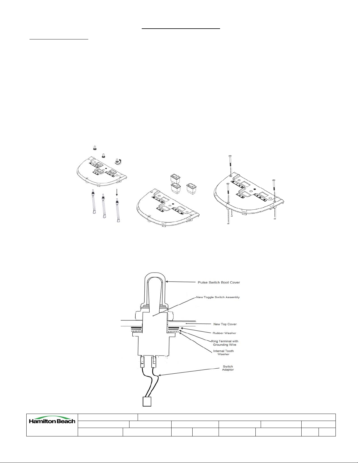
5. Remove the three screws from the top cover. A retaining washer holds the screws from falling out of the
cover. There are new washers with the kit.
6. Open the service kit.
7. Install each new pulse switch with internal tooth washer, grounding ring terminal and rubber washer to new
top cover. Then install each boot to top of cover and switch.
Revision Description: Production Release
4421 Waterfront Drive
Glen Allen, VA 23060
ENG-FRM-RIC-4.32, Rev. E
Request Number: HQE-8592 Revision Date: 11/06/09 Approved by: HQE-8592
Issue Code(s): CS, SP Page:
1 of 2
Document #:
520004300
Rev:
A

Technical Service Document
PROPRIETARY RIGHTS NOTICE
and has been provided to you for a limited purpose. It must be returned or destroyed upon request. Disclosure, reproduction or use of this document and any information
contained within it, in full or in part, for any purpose is forbidden without the prior written consent of HBB. No photographs may be taken of any article fabricated or assembled
from this document without the prior written consent of HBB.
This document and all information contained within it is the property of Hamilton Beach Brands, Inc. (HBB). It is confidential and proprietary
8. Install the screws (removed from the old top cover) to the new top cover using the retaining washers
supplied.
9. Install speed switch(s) in the new top cover. Orient the switch so the edge with the two terminals aligns to
the III speed edge of the top cover.
10. Attach electrical connections as described above.
11. Remove the ground wire screw from the housing in the three spindle machine and from the top of the motor
in the single spindle machine. Add the ground wire from the new pulse switch to the screw and replace it.
12. Make sure that all switches are oriented properly and that wires are not going to come in contact with the
motor(s). Assure top rubber motor mount(s) is in position. Align top cover and screw in place.
13. Plug machine into grounded outlet and test all switches including speed switches.
Revision Description: Production Release
4421 Waterfront Drive
Glen Allen, VA 23060
ENG-FRM-RIC-4.32, Rev. E
Request Number: HQE-8592 Revision Date: 11/06/09 Approved by: HQE-8592
Issue Code(s): CS, SP Page:
2 of 2
Document #:
520004300
Rev:
A
 Loading...