

Page 1

D
ura
blenD Resin®
M
a
d
e
w
i
t
h
P
r
i
d
e
i
n
t
h
e
U
S
A
DuraResin Blend®
Water Softener
Models:
SA-HB-40-DB-CERT
SA-HB-48-DB-CERT
Page 2

Hamilton Beach Owner’s Manual | 3
MODEL: SA-HB-40-DB-CERT Water Softener
Operating Temperature: 34o–120oF
Operating Pressure: 20–60 psi (#5 injector); 61-120 psi (#4 injector)
Voltage: 110V 60 cycles
Rated Service Flow: 15.2 GPM @ 15 psi
Rated Softening Capacity: 14.2 @ 3.0 (#5 injector)
(Kilograins / Pounds of Salt) 24 @ 7.5, 37.0 @ 15 (#4 injector)
Max Flow Rate to Drain: 4.0 GPM
Amount of High Capacity Resin: 1.25 ft
3
Rated Efficiency: 4,720 grains @ 3.0 lbs
**Observe all state and local plumbing codes.
**This softener conforms to NSF/ANSI 44 for the specifically claimed
performance.
**The efficiency of the softener is valid only at the stated salt
dosage.
Manufactured By:
R&M Manufacturing
28 South 1550 West
Lindon UT 84042-1617
(801) 785-5557
pn: LBL-HB-40-CERT
CAUTION: Do NOT use with water that
is microbiologically unsafe or of unknown
quality without adequate disinfection
before or after the system.
pn: LBL-HB-48-CERT
MODEL: SA-HB-48-CERT Water Softener
Operating Temperature: 34o–120oF
Operating Pressure: 20–60 psi (#5 injector); 61-120 psi (#4 injector)
Voltage: 110V 60 cycles
Rated Service Flow: 18 GPM @ 35 psi inlet
Rated Softening Capacity: 15.1 @ 3.6 (#5 injector)
(Kilograins / Pounds of Salt) 26.0 @ 9.0, 39.7 @ 18 (#4 injector)
Max Flow Rate to Drain: 3.5 GPM
Amount of High Capacity Resin: 1.5 ft
3
Rated Efficiency: 4,210 grains @ 3.6 lbs
**Observe all state and local plumbing codes.
**This softener conforms to NSF/ANSI 44 for the specifically claimed
performance.
**The efficiency of the softener is valid only at the stated salt dosage.
Manufactured By:
R&M Manufacturing
28 South 1550 West
Lindon UT 84042-1617
(801) 785-5557
CAUTION: Do NOT use with water that
is microbiologically unsafe or of unknown
quality without adequate disinfection
before or after the system.
2 | Hamilton Beach Owner’s Manual
See pages 8 through 11 for:
• pre-installation checklist
• installation instructions
• start-up directions
Page 3

Table of Contents
Table of Contents
Introduction . . . . . . . . . . . . . . . . . . . . . . . . . . . . . . . . . . . . . . . . . . . . .4
Equipment Specifications . . . . . . . . . . . . . . . . . . . . . . . . . . . . . . . . . .4
Job Specifications Sheet . . . . . . . . . . . . . . . . . . . . . . . . . . . . . . . . . . .5
Sizing Information . . . . . . . . . . . . . . . . . . . . . . . . . . . . . . . . . . . . . . .5
Water Conditioning . . . . . . . . . . . . . . . . . . . . . . . . . . . . . . . . . . . . . . .6
Homeowner Maintenance . . . . . . . . . . . . . . . . . . . . . . . . . . . . . . . . . .6
Manual Bypass Valve . . . . . . . . . . . . . . . . . . . . . . . . . . . . . . . . . . . . .8
Pre-Installation Checklist . . . . . . . . . . . . . . . . . . . . . . . . . . . . . . . . . .8
Detailed Installation Instructions . . . . . . . . . . . . . . . . . . . . . . . . . . . .9
Start-Up Rinsing Procedure . . . . . . . . . . . . . . . . . . . . . . . . . . . . . . .10
Battery Backup Feature . . . . . . . . . . . . . . . . . . . . . . . . . . . . . . . . . .12
Programming the Control Valve . . . . . . . . . . . . . . . . . . . . . . . . . . . .12
Level I Programming . . . . . . . . . . . . . . . . . . . . . . . . . . . . . . . . . . . .13
Level I Programming Parameters . . . . . . . . . . . . . . . . . . . . . . . . . . .13
Level II Programming . . . . . . . . . . . . . . . . . . . . . . . . . . . . . . . . . . . .15
Level II Programming Parameters . . . . . . . . . . . . . . . . . . . . . . . . . .15
Level I and II Default Settings . . . . . . . . . . . . . . . . . . . . . . . . . . . . .16
System Capacity Inputs . . . . . . . . . . . . . . . . . . . . . . . . . . . . . . . . . .17
Flow Diagrams . . . . . . . . . . . . . . . . . . . . . . . . . . . . . . . . . . . . . . . . .18
Control Valve Diagram . . . . . . . . . . . . . . . . . . . . . . . . . . . . . . . . . . .20
Systems Diagram . . . . . . . . . . . . . . . . . . . . . . . . . . . . . . . . . . . . . . .21
Troubleshooting . . . . . . . . . . . . . . . . . . . . . . . . . . . . . . . . . . . . . . . .22
Notes . . . . . . . . . . . . . . . . . . . . . . . . . . . . . . . . . . . . . . . . . . . . . . . . .26
Hamilton Beach Owner’s Manual | 3
Page 4
Hamilton Beach Owner’s Manual | 5
Introduction / Equipment Specification
Introduction
Your Hamilton Beach owner’s manual is designed to
assist owners and installers with the installation, operation,
and maintenance of your new water-conditioning system. The
simplified photo format is designed to assist all aspects of
operation.
In the event service or plumbing changes are required, contact
your local authorized Hamilton Beach dealer. If further
assistance is required, call 800.685.8440.
Equipment Specifications
Working Pressure . . . . . . . . . . . . . . . . . . . . . . . . . . . 20 psi to 120 psi
Voltage . . . . . . . . . . . . . . . . . . . . . . . . . . . . . . .102 to 132 vac, 60 Hz
Current . . . . . . . . . . . . . . . . . . . . . . . . . . . . . . . . . . . . . . . . . . . 50 mA
Transformer . . . . . . . . . . . . . . . . . . . . . Wall Mount (indoor use only)
Operating Temperature . . . . . . . . . . . . . . . . . . . . . . . . 34o F to 120o F
Humidity . . . . . . . . . . . . . . . . . . .10% to 100%, Condensing Allowed
Service Connections . . . . . . . . . . .3/4”, 1”, 11/4” Copper Tube Adapter
Brine Line Connection . . . . . . . . . . . . . . . . . . . . . . . . . . . .3/8” Tubing
Drain Line . . . . . . . . . . . . . . . . . . . . . . . . . . . . . . . . . . .1/2” NPT Male
Water Flow . . . . . . . . . . . . . . . . Accurate over range of .5 to 23 gpm
4 | Hamilton Beach Owner’s Manual
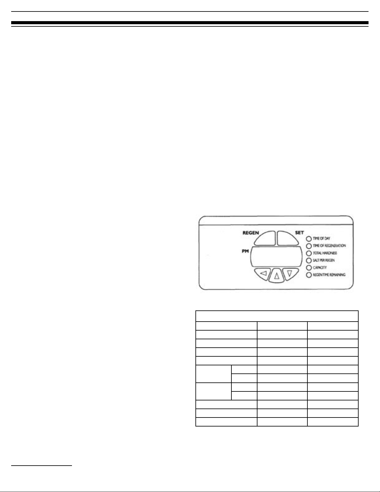
Figure 1: Control valve interface.
System Specifications
SA-HB-40-DB-CERT SA-HB-48-DB-CERT
Resin Tank Size 10x44” 12x48”
Resin Volume 1.25 ft
Refill Controller 0.35 gpm 0.35 gpm
Backwash Controller 2.8 gpm 2.8 gpm
Salt Tank Size 15x40” 15x40”
Capacity 450 lbs 450 lbs
Operation
Temperature
Flow Rate 15.2 gpm 18.0 gpm
Pressure Drop 15.0 psi 15.0 psi
Max Flow to Drain 4.0 gpm 3.5 gpm
Table 1: System specifications
Min 34
Max 120
3
o
o
1.50 ft
34
120
3
o
o
Page 5

Job Specification Sheet
Homeowner._________________________________________________
Dealer._______________________________________________________
Date of Installation.__________________
Installers Name. ____________________
Model #._____________________Serial #._________________________
Water Characteristics
__________Hardness as CaCo3 (check one____gpg or____ Mg/L)
__________Iron (ppm)
________Water pressure (psi)
Job Specification Sheet / Sizing Information
__________ PH
___Yes ___ No Pressure regulator.
__________Other ____________ , __________ Other ___________.
__________Other ____________, __________Other ___________.
Sizing Information
All Water is treated except:___Front hose bib __Rear hose bib ___Kitchen
___Toilets ____Other___________________________________________.
Sizing formula: On the average, a person uses 70 gallons of water per day
(20 gallons hot water, and 50 gallons cold water.
Example:
Daily usage: 70 gallons per person
Family size: x 6 persons
Total family daily usage: 420 gallons
Hardness: x 20 grains per gallon
Total removal per day: 8,400 grains
Actual Usage
Daily usage: 70 gallons per person
Family size: x _________ persons
Total family daily usage: _________ gallons
Hardness: x _________ grains per gallon
Total removal per day: _________ grains
Hamilton Beach Owner’s Manual | 5
Page 6
Hamilton Beach Owner’s Manual | 7
Water Conditioning / Homeowner Maintenance
Water Conditioning Homeowner Maintenance
Glossary of Terms
Hardness is comprised of dissolved calcium and magnesium.
As a general rule water is considered to be extremely hard
when over 10 gpg of hardness, hard when 6-10 gpg, mildly
hard when 3-6 gpg, slightly hard when 1-2 gpg and soft when
0 gpg.
Hard
Soft Water
0–1 gpg
1.0–3.5 gpg
Moderately Hard
Measurements
3.5–7.0 gpg
: Your Hamilton Beach water system registers
hardness in grains per gallon (gpg). Most water analysis reports
register hardness in milligrams per liter (Mg/L) or parts per
million (ppm). To convert either Mg/L or ppm to gpg, divide
the indicated amount by 17.1.
Example: Water report indicates total hardness of
350 Mg/L, divide this number by 17.1 to get the
gpg, which would be 20.4 gpg.
Ion Exchange
: Your water conditioning system utilizes ionexchange media, also referred to as resin, to effectively remove
hardness ions from the water and replace them with sodium
ions. Exhausted resin beads are rinsed with a salt solution
called “brine.” This causes the resin to exchange hardness ions
for the sodium ions, returning the resin to its sodium state.
Very Hard
7.0–10.5 gpg
10.5+ gpg
Extremely Hard
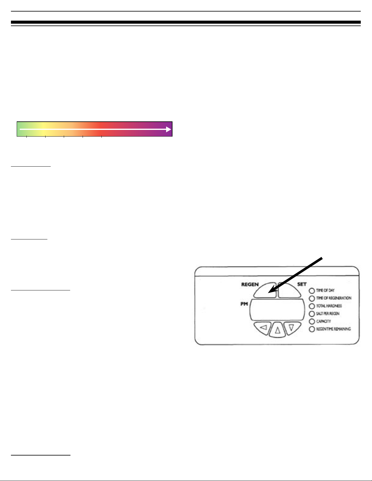
Manual Regeneration
Occasionally you may find it necessary to initiate a manual
regeneration. This is done by pressing the [REGEN] button on
the front of the display. (See Figure 2.) When you press the
[REGEN] button, the control performs a full regeneration of
the water conditioner immediately.
In the event the system is allowed to run out of salt, it will be
necessary to run “Back to Back” regenerations. This can be
done easily by pressing the [REGEN] button one time, waiting
at least one minute and pressing the [REGEN] button again.
------------------------------------------------------------------------------------Note: The second regeneration will begin immediately after the
first is completed.
-------------------------------------------------------------------------------------
“Back to Back” regenerations are necessary if full exhaustion
occurs due to low regenerate levels or system malfunction.
The system works on a highly efficient proportionate-brining
method. When the system is not aware of the lack of proper
regenerate(salt) a larger portion of the resin bed becomes
exhausted.
[REGEN] Button
Proportionate Brining
: Your Hamilton Beach System utilizes
an advanced microprocessor to control the amount of
regenerant proportionate to the amount of exhausted resin.
It uses enough salt to bring the system back to 100% capacity.
The microprocessor also incorporates a variable-reserve feature
to enable the system to adjust to patterns of usage, thus
maintaining high efficiency.
6 | Hamilton Beach Owner’s Manual
Figure 2: Control valve interface: regeneration button (REGEN).
Page 7

Homeowner Maintenance (Continued)
Calendar Day Override Feature
Hamilton Beach systems have an optional calendar day
override feature. The systems come pre-programmed with
this feature turned off. To activate this feature, see Level II
Programming instructions. This feature overrides the registered water volume and initiates a regeneration based on the
days selected even if there has been 0 water usage registered.
This feature is sometimes used if long absences from the home
occur. This ensures a freshly regenerated bed of resin and
minimizes the chance of resin fouling.
Regeneration:
Salt is used to regenerate the system. Salt pellets are generally cleaner
than extra-course rock salt. DO NOT use salt blocks as they may contain
vitamins or other undesirable additives. Add salt to the brine tank when it
drops to within 12 inches of the bottom.
Dry Brine Tank:
Hamilton Beach Systems use a dry brine tank. Since the system
determines the amount of solution necessary to regenerate
the exhausted resin, water is sent to the brine tank as part of
the regeneration sequence in an amount proportionate to the
exhausted resin that needs to be regenerated.
Note: While it is a dry brine tank, you will see approximately 1” of water
in the bottom of the tank during normal service. This amount of water is
necessary for the proper function of the brine air-check assembly. If water
amount exceeds this level while in normal service position, refer to the
troubleshooting guide; or contact your local authorized Hamilton Beach
dealer or qualified plumbing professional
Disinfection of Water Conditioners:
The construction materials of the water conditioning system
do not contaminate the water supply. However, we
recommend that the conditioner be disinfected after
installation. Periodic disinfection is recommended for all
conditioners. Use the following method of disinfection to
clean your system:
• Sodium Hypochlorite 5.25%: Sodium Hypochlorite
solutions can be used with polystyrene resin, synthetic
gel zeolite, greensand, and bentonites and are available
under trade names such as Clorox*. Adjust the dosage
if stronger commercial solutions are used.
The recommended dosage for a 5.25% depends on
your system size. Use the following amount depending
on your system model:
Model: SA-HB-40-DB-CERT . . . . . 1.5 Fluid ounces
SA-HB-48-DB-CERT . . . . . 1.8 Fluid ounces
Add the sodium hypochlorite solution to the brine well of the
brine tank. Make sure that the brine tank has water in it so the
solution is carried into the conditioner. Proceed with manual
regeneration. Refer to the Manual Regeneration section on
page 6.
* Clorox is a trademark of the Clorox Co.
Battery Backup Feature:
Brine Tank Cleaning:
Insoluble materials gradually build up in the salt tank
depending on the levels found in the salt. As a general rule,
inspect the brine tank once a year when the salt level is low.
To clean the tank, disconnect the brine-line connection, rinse
out any insoluble build-up, reconnect the brine-line, and add
one inch of fresh water. Then totally refill the tank with salt.
Setting Time Clock:
Your clock should indicate the current time of day, provided
the clock is set correctly. The system will clean at the specified
time of regeneration.
Your Hamilton Beach system has a battery backup feature. (See
Figure 3.) During a power outage the display will be blank but
the microprocessor will continue registering water flow. The
system will not initiate regeneration during a power outage;
instead it will wait until full power returns.
It is recommended the battery be replaced once a year or after
any extended power outage. The battery is a standard 9-volt.
Detailed instructions can be found in the programming section
on page 12 of this manual.
Figure 3: Battery installation for
battery backup feature.
Hamilton Beach Owner’s Manual | 7
Page 8

Hamilton Beach Owner’s Manual | 9
Manual Bypass Valve / Pre-Installation Check List
Manual Bypass Valve (Optional)
Your Hamilton Beach system is equipped with a manual
bypass valve. (See Figure 4.) This valve is to be used if you
want to stop the flow of water through the equipment but still
allow untreated water into your home.
Figure 4: Bypass valve.
For example, a bypass valve may be used if a leak occurs in
the system or when the homeowner(s) will be gone from the
home for an extended period of time.
------------------------------------------------------------------------------------Note:
It is recommended that the bypass valve knobs be engaged and
disengaged (turned in and out of service) once a year to ensure
that the O-rings are functioning. This allows the bypass valve
to turn more freely if it becomes necessary.
-------------------------------------------------------------------------------------
Do not use soft vinyl tubing, 3/8” or smaller
tubing. Do not expose tubing to freezing.
When barb drain fittings are used, always use a
hose clamp to secure the tubing to the fitting. Do
not connect the drain line to the overflow line on
the salt storage container. Installation of the drain
line should be in accordance with all state and
local plumbing codes.
o Installation Site: When choosing the proper
locations for the equipment, consider the
following factors:
• Proximity to drain.
• Proximity to electrical outlet.
• Access to plumbing; it is recommended
that when possible both hot and cold water
be treated with the exception of outside
taps. Kitchen cold is optional. Additional
equipment may work better with treated
water. Consult your dealer for details and
the best option for the application. (See
Figure 5.)
o Unpacking System: After removing the system
from the box, inspect the system for any
concealed damage that may have occurred
in shipping. If damage occurred, contact your
dealer for details. Do not install if the system has
sustained damage.
Pre-Installation Check List
The following items should be checked and verified prior to
the installation of the equipment. Under certain circumstances,
as indicated, additional procedures or pieces of equipment
may be recommended.
o Water Pressure Verification: A minimum
water pressure of 20 psi is required for normal
operation. Maximum water pressure is 120 psi.
o Electrical Requirements: The system includes a
12-volt transformer to be plugged into a standard
110 volt 60 Hz current. If additional cord length is
required, a 15 foot extension is available.
(AVP-1000907, see pg. 11)
o Drain-Line Connection: Choose a location close
to a drain to put your brine tank. Avoid overhead
runs in excess of 25 feet. Drain line must be a
minimum of ” inside diameter.
8 | Hamilton Beach Owner’s Manual
Whole-home media
filtration system
Water conditioner
Figure 5: Water-using appliances and fixtures in reference to
water-conditioner system installation site.
Page 9

Detailed Installation Instructions
Detailed Installation
Instructions
General Installation Warnings
The following general warnings should be observed when
installation and/or general service maintenance is performed.
• Plumbing connections should be done in
accordance with state and local plumbing codes.
• Do not use with water that is microbiologically
unsafe or of unknown quality without adequate
disinfection before or after the system.
• Drain lines should be ” minimum for drain line
flows up to 7 gpm. Flows above 7 gpm or runs in
excess of 20 feet require ” drain line.
WARNING: Never connect drain line directly into a drain, sewer line or
trap. Plumbing code requires installation to allow an air gap* between the
drain line and the wastewater to prevent the possibility of sewage backsiphoning into the conditioner. (See Figure 6.) Sewage backup can have
harmful health effects.
• A Brine Tank over-flow line of ” ID 5/8” OD is
recommended for the brine tank. This line should
run from the barb fitting on the side of the tank to
an unobstructed drain. (See Figure 7.)
• Each system comes standard with a high-pressure
injector.* It may be necessary to change the
injector (see Figure 8) to match your incoming
water pressure. (See Table 2 for injector sizes.)
*Standard Injector (High Pressure)
Brine tank
Overflow fitting
installed
Connect 1/2” (1.3 cm) ID tubing
or hose and run to drain.
Figure 6: Correct air-gap installation.
* Plumbing code air gap is one inch above the flood plane.
• All electrical connections must be connected
according to local codes. The electrical source
must be uninterrupted. Install grounding strap on
metal pipes.
• Do not use pipe dope or other types of liquid
sealants on any threads. Teflon tape must be used
on the drain line ” threads and also on the 3/8”
brine-line connections.
Note: Factory has teflon taped these fittings.
• Use caution if soldering inlet, outlet, or drain lines.
Excess heat will damage the control valve and/or
bypass valve.
Figure 7: Brine tank tubing connection with overflow fitting.
Injector
Injector cap
Injector
Figure 8: Injector screen and cap installation.
Injector Selection
Water Pressure Injector Part Number
20–60 psi
(138–414 bar)
61–120 psi
(420–827 bar)
Table 2: Injector selection based on water pressure.
AVP-1032980 (#5 Injector)
AVP-1032977 (#4 Injector)
Hamilton Beach Owner’s Manual | 9
Page 10
Hamilton Beach Owner’s Manual | 11
Start-up Rinsing Procedure
Start-Up Rinsing Procedure
(Bypass valve is optional)
1. With the plumbing, drain line, and overflow
connections completed, slowly open the water
supply allowing the lines to pressurize.
Note: The optional bypass should still be in bypass mode as
shown in Figure 9.
Once the air clears and water begins to run to the
drain, open the inlet valve (only) to the full open
position and allow the water to run to the drain in
purge for a minimum of 20 minutes. (See Figure
11.)
Outlet
Inlet
Figure 9
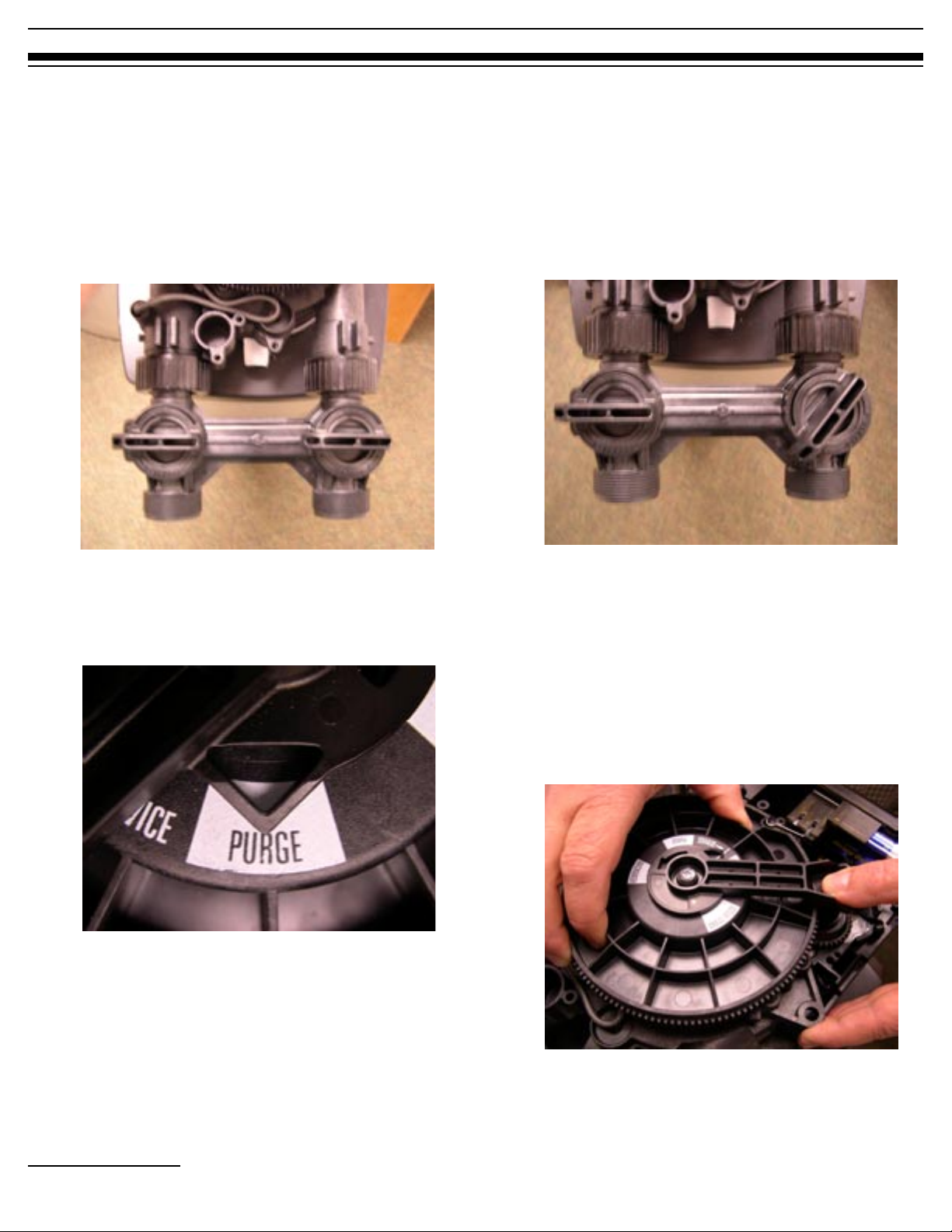
2. With the control valve unplugged, manually
advance the control valve by depressing the drive
gear and rotating the main system gear to the
purge position. (See Figure 10.)
Figure 10
Outlet
Inlet
Figure 11
4. After the 20-minute purge cycle, manually
advance the main gear to the backwash cycle and
allow to run for a minimum of 10 minutes. (See
Figure 12.)
Note: when advancing the main gear manually while under
water pressure it is normal for the gear to encounter resistance
as the valve chambers depressurize. If resistance occurs,
pause five seconds to allow the valve to depressurize before
advancing to the next step.
3. Slowly open the inlet valve (only) on the bypass
valve allowing the system to pressurize. It is
normal to hear air blowing to the drain during this
procedure.
10 | Hamilton Beach Owner’s Manual
Figure 12
Page 11

Start Up Rinsing Procedure (con’t)
5. After the ten-minute backwash cycle, manually
advance the control valve to the brine refill
position for ten minutes allowing water to flow
into the brine storage tank. (See Figure 13.)
Figure 13
Once water begins to flow into the tank fill the
brine tank with a minimum of 100 lbs of salt
pellets.
6. After the ten-minute refill time, manually advance
the control valve to the service position. (See
Figure 14.)
7. Plug in the control valve. (See Figure 15.)
Figure 15
8. If it is necessary to extend the length of the
transformer cord, an optional 15 foot (4.6-m)
extension cord is available, (See Figure 16), or the
cord may be spliced as follows:
a. Strip insulation from wire 5/16 inch (7.87 mm)
from wire end.
b. Insert stripped wire into barrel of connector
and crimp. For best results, crimp twice per
wire as shown in Figure 17 .
Neither splice connections nor extension wire
are supplied. They are available at hardware or
electrical stores.
Figure 14
Figure 16
(AVP-1000907)
Figure 17
Hamilton Beach Owner’s Manual | 11
Page 12

Hamilton Beach Owner’s Manual | 13
Battery Backup/ Programming the Control Valve
Battery Backup Feature
Your Hamilton Beach softening system has a battery backup
feature that allows the control to continue monitoring water
flow and maintain the proper time of day during short power
outages. The control uses a standard 9-volt battery (not
supplied).
During a power outage, the display will be turned off and the
motor will not run, but the control will continue to monitor
water flow. If power is out and a regeneration is needed, the
regeneration will be delayed until power is restored. If power
is lost during the regeneration, the control will resume the
regeneration when power is restored.
While batteries may last for over a year, the factory recommends
replacing the battery every year. During an interruption in
power supply, a typical new 9-volt alkaline battery provides
approximately two days of power for the control. Older
batteries and those exposed to temperature over 750 F (23.9O C)
provide power for shorter periods of time.
The control can be operated without a battery, but the control
will not measure water usage or time while the power is off.
The control will save all important operating information and
programming data during a power outage. No reprogramming
is necessary.
Programming the Control
Valve
You are now ready to continue programming the control.
Programming can be done in both Level I and Level II.
Accompanying tables are included for selecting the correct
settings for each level .
Note: The system has been pre-programmed with default settings based
on model number and ultra-high efficiency settings at a water hardness of
15 grains per gallon. While the system may operate with these settings,
the following Level I & II settings may need to be changed to meet the
actual operating conditions and achieve maximum system capacity and salt
efficiency.
Figure 18
Note: It is recommended that the battery be replaced every year or after
any extended power outage.
To install a battery:
1. Remove the control valve cover.
2. The battery pocket is located in the upper left
corner of the control as shown in Figure 18.
3. Insert the battery, matching up negative and
positive posts.
12 | Hamilton Beach Owner’s Manual
Page 13

Programming Guide
Level I Programming
Parameters
P1 Time of day
P2 Time of regeneration
P3 Water hardness (grains per gallon—gpg)
P4 Salt usage per regeneration (lbs)
P5 System capacity (Kg)
Table 3: Level I programming parameters overview.
Default settings for models:
SA-HB-40-DB-CERT (40DB)
SA-HB-48-DB-CERT (48DB)
(Ultra-high efficiency settings)
Setting Description 40DB 48DB
P1 Time of day Set to current time of day
P2 Time of regeneration 2 a.m. 2 a.m.
P3 Water hardness Set in field Set in field
P4* Salt usage 3.0 lbs 3.6 lbs
P5 System capacity 14.1 Kg 15.2 Kg
Table 4: Level I programming default settings.
Level I Programming
Parameters
P1
Time of Day AM or PM
Ranges: 1:00 to 12:59 or 00:00 to 23:59
Minimum Increments: 1 Min.
Units of Measure: Hours & Minutes
Range: Depends on the value selected for P13
P2
Time of Regeneration
Ranges: 1:00 to 12:59 a.m. or p.m, 00:00 to 23:59
Minimum Increments: 1 Min.
Units of Measure: Hours & Minutes
Range: Depends on the value selected for P13
P3
Water Hardness Setting
Range: 3 to 250 (grains per gallon) gpg / 30 to 2500
(milligrams per liter) Mg/L
* Default settings are representative of ultra-high efficiency.
Level I Settings are identified as those that have an LED
indicator on the front panel. The green indicator illuminates
next to the name of the active control setting. (See Figure 19.)
Pressing the down arrow [$ ] button displays the Level I settings
in order. By continuing to press the down arrow [$] button, the
settings start over beginning with the time of day. Pressing the
up arrow [ # ] button displays the settings in reverse order.
Figure 19: Control valve interface.
Minimum Increments: 1 for (gpg), 10 for (Mg/L)
Units of Measure: Grains per gallon (gpg) / Milligram
per liter (Mg/L)
Range: Unit of measure depends on the value selected
for P12. Test water hardness (compensated hardness)
and enter that value.
P4
Salt Amount (maximum)
Ranges: 0.5 to 99.5 (pounds) or 0.1 to 25.5
(kilograms)
Minimum Increments: 0.5 (pounds) or 0.1
(kilograms)
Units of Measure: Pounds or Kilograms
Range: Unit of measure and default depends on value
selected for P12.
P5
System Capacity
Ranges: 0.1 to 140 Kgr or 0.01 to 14.0 Kgr
Minimum Increments: 0.1 Kgr or 0.01 Kgr
Units of Measure: Kgr or Kilograms
Range: Depends on value selected for P12
Hamilton Beach Owner’s Manual | 13
Page 14

Hamilton Beach Owner’s Manual | 15
Programming Guide
Changing the Settings
To change the settings press the [SET] button on the far right.
The digit of the display starts flashing. If you want to change
this number, press the up arrow [# ] button to increase the
number or the down arrow [ $ ] button to decrease the number.
To skip the number without changing, press the left arrow [! ]
button. When you reach the far left digit, pressing the left arrow
[! ] button will return you to the far right digit.
Note: If you press and hold either the up or down arrow [ # ] [ $ ] button for
more than 1 second, the flashing number will increase or decrease at ten
counts per second.
When the number is correct, press the left arrow [ ! ] button.
The far right digit stops flashing and the next digit to the left
starts flashing.
You can only change the flashing number. Continue changing
numbers until you reach the desired setting. Press the [SET]
button. The numbers stop flashing and the control accepts the
new setting. After approximately 30 seconds, the control starts
alternating the display between Time of Day and Capacity.
Note: If the new setting is not accepted because it was outside the
allowable range, the old value will be displayed. Refer to the table guides
for the correct settings. (Default settings can be found on Table 6, on page
15.)
Time of Day
Press the [SET] button. The display will show the Time of Day
with the minutes digit blinking. If you want to change this
number, press the up arrow [#] button to increase the number
or the down arrow [$ ] button to decrease the number.
To skip the number without changing, press the left arrow [! ]
button. The first number stops flashing and the next number
starts flashing. You can only change the flashing number. When
you have reached the far left digit, pressing the left arrow [!]
button returns you to the far right digit. Continue changing
numbers until you reach the desired setting. Press the [SET]
button again to enter the value.
Time of Regeneration
The next value displayed is the Time of Regeneration, which is
similar to Time of Day programming. It has a default setting
of 2:00 a.m. If 2:00 a.m. is acceptable, press the down arrow
button [ $ ] .
If this is not acceptable, press the [SET] button and change the
numbers. Press the [SET] button again to enter the value.
Water Hardness
The next setting displayed is the Water Hardness in grains per
gallon(gpg). It is recommended that a water test be performed
at the time of installation. This Hamilton Beach is designed to
run on one water source. If multiple water sources are used, it
will be necessary to change the water hardness settings to match
the current water source.
The default setting is 15 grains per gallon of water hardness.
If this is not accurate, press the [SET] button and enter a new
value. U.S. settings allow any value between 3 and 250 grains
per gallon. Metric settings allow any value between 30 and 2500
milligrams per liter. Press the [SET] button again to enter the
new value.
Salt Amount
Capacity is the next value displayed and is expressed in
Kilograins (Kgr).
The pre-set default values for each model are listed in Table 5.
To change these values, press the [SET] button and enter a new
value. Any value between 0.1 and 14.0 Kilograins is allowed.
Note: If the calculation for the system capacity exceeds 9999 gallons (99.99
cubic meters) (P5, Capacity, divided by P3, Hardness), the control will
display 9999 for capacity until the water usage has dropped the remaining
capacity below that number. When water is flowing through the system, the
colon in the Time of Day display will blink.
Salt Settings (Ultra-High Efficiency Settings)
Model Capacity Default Salt Default
SA-HB-40-DB-CERT 14.1 Kgr 3.0 lbs
SA-HB-48-DB-CERT 15.2 Kgr 3.6 lbs
Table 5: Salt settings to obtain ultra-high efficiency.
You have now finished Level I programming. The display will
alternate between the Time of Day and Capacity if no keys are
pressed for 30 seconds. The Capacity value displayed is the
volume remaining in gallons (cubic meters for metric) before a
regeneration is needed.
14 | Hamilton Beach Owner’s Manual
Page 15

Level II Programming
The Level II programming has been programmed by the
manufacturer to the settings in Table 6. The changing of preset
values can be done at this time. Refer to Level II programming
parameters in Table 6 for options.
Note: It is not recommended that homeowners change these values
without checking with local water-treatment professional for details.
Incorrect programming can cause system malfunction and the possible
need for a field service call to reprogram the system. System programming
is not covered under warranty.
To access Level II programming, simultaneously hold down the
up [ # ] and down [$ ] arrows. This will allow you to enter Level
II settings P6 through P19. (See Table 6.)
Level II Programming
Programming Guide
Parameters
Level II Programming Parameters
Parameter Description Range Minimum
P6 Refill controller 1–99 1 gpm .35 gpm, both models
P7 Brine draw value 1–99 1 Minutes 15, both models
P8 Not used n/a n/a n/a n/a
P9 Backwash time 3–30 1 Minutes Skip this parameter to accept the default or enter a value
P10 Slow rinse time 8–125 1 Minutes SA-HB-40-DB-CERT = 67
P11 Fast rinse time 2–19 1 Minutes Skip this parameter to accept the default or enter a value
P12 Units of measure 0–1 1 0 = U.S.
P13 Clock mode 0–1 1 0 = 12-hour clock
P14 Calendar override 0–30 1 days 0 = no calendar override
P15 Reserve type 0–3 1 0 = variable reserve
P16 Fixed reserve capacity
or initial average
value
P17 Operation type 0–1 1 0 = Not used
P18 Salt / capacity change
lock out
P19 Factory defaults DO NOT
Table 6: Level II programming parameters.
0–70 1 percent of
0–1 1 0 = none
CHANGE
Increments
1 Loads in factory default values. DO NOT CHANGE THIS
Units of
Measure
capacity
Notes
SA-HB-48-DB-CERT = 80
1 = Metric
Skip this parameter to accept the default (U.S.)
1 = 24-hour clock
Skip this parameter to accept the default (12-hour)
Skip this parameter to accept the default (no override)
Description depends on the value entered for P15 (Reserve
type). Skip this parameter to accept the default.
1 = 5-cycle counter current
1 = salt / capacity change locked out
Skip this parameter to accept the default (no lock out)
PARAMETER.
Hamilton Beach Owner’s Manual | 15
Page 16

Hamilton Beach Owner’s Manual | 17
Programming Guide
Level I and II Default Settings
The following table represents preset values programmed into the systems at the factory for both levels I
and II for the model shown. (See Table 7.)
Level I Parameters
Name Description SA-HB-40-DB-CERT SA-HB-48-DB-CERT
P1 Time of day Set in field Set in field
P2 Time of regeneration 2:00 a.m. 2:00 a.m.
P3 Hardness Set in field Set in field
P4 Salt amount 3.0 lbs 4.0 lbs
P5 Capacity 14.1 Kgr @ 3.0 lbs of salt 15.2 Kgr @ 3.6 lbs of salt
Level II Parameters
P6 Refill controller 0.35 gpm 0.35 gpm
P7 Brine draw value 3.0 lbs @ 7 min w/ 5 bump injector
P8 Not used n/a n/a
P9 Backwash time 3.9 min 3.9 min
P10 Slow rinse time 75.5 min @ 3.0 lbs with 5 bump injector
P11 Fast rinse time 3.5 min 3.5 min
P12 Units of measure 0 0
P13 Clock mode 0 0
P14 Calendar override 0 0
P15 Reserve type 0 0
P16 Fixed reserve capacity
or initial average value
P17 Operation type 1 1
P18 Salt / capacity change
lock out
P19 Factory defaults 9 9
7.5 lbs @ 26 min w/ 4 bump injector
15.0 lbs @ 51 min w/ 4 bump injector
62.0 min @ 7.5 lbs with 4 bump injector
57.0 min @ 15.0 lbs with 4 bump injector
n/a n/a
0 0
Table 7: Level I and II programming default settings.
4.0 lbs @ 9 min w/ 5 bump injector
9.0 lbs @ 31 min w/ 4 bump injector
18.0 lbs @ 61 min w/ 4 bump injector
75.5 min @ 3.0 lbs with 5 bump injector
62.0 min @ 7.5 lbs with 4 bump injector
57.0 min @ 15.0 lbs with 4 bump injector
16 | Hamilton Beach Owner’s Manual
Page 17

System Capacity Inputs
System Capacity Inputs
Salt Settings and Capacity (Kgr)
Lbs of Salt SA-HB-40-DB-CERT SA-HB-48-DB-CERT
3.0 14.1
3.6 15.5 15.2
4.0 16.5 15.5
5.0 19.0 18.0
6.0 22.0 21.0
7.0 24.0 23.5
7.5 24.4
8.0 25.6 25.0
9.0 27.9 26.1
10.0 30.0 30.0
11.0 31.9 31.5
12.0 33.6 33.0
13.0 35.1 34.0
14.0 36.4 35.2
15.0 37.1
16.0 38.4 37.0
17.0 39.1 38.0
18.0 39.6 39.8
19.0 39.9 41.0
20.0 40.0 41.5
21.0 n/a 42.0
22.0 n/a 43.0
23.0 n/a 44.0
24.0 n/a 45.2
25.0 n/a 45.9
26.0 n/a 46.5
27.0 n/a 47.2
28.0 n/a 48.0
Table 8: System capacity by pounds of salt.
40
40
40
n/a
24.3
36.0
SA-HB-40-DB-CERT
30
48
25
20
15
10
Salt Setting (lbs)
5
48
0
0 10 20 30 40 50
Capacity (Kgr)
Figure 19
SA-HB-48-DB-CERT
30
25
48
20
15
10
Salt Setting (lbs)
5
0
0 10 20 30 40 50
Capacity (Kgr)
Figure 20
40
SA-HB-40-DB-CERT certified capacity at salt setting
48
SA-HB-48-DB-CERT certified capacity at salt setting
Note: The 3.0 lbs salt setting (40 DB model) and the 3.6 lbs salt setting (48
DB model) are certified using the 5 bump injector. The 7.5 lbs (40 DB), 15
lbs (40 DB), 9 lbs (48 DB), and 18 lbs (48 DB) are certified using the 4 bump
injector.
Hamilton Beach Owner’s Manual | 17
Page 18

Hamilton Beach Owner’s Manual | 19
Flow Diagrams
Flow Diagrams
Figure 20 Figure 21
18 | Hamilton Beach Owner’s Manual
Figure 22
Figure 23
Page 19

Flow Diagrams
Figure 24
Figure 25
Figure 26
Hamilton Beach Owner’s Manual | 19
Page 20

Hamilton Beach Owner’s Manual | 21
Control Valve Diagram
Control Valve Diagram
20 | Hamilton Beach Owner’s Manual
Page 21

Control Valve Parts
Code Part Number Description Qty
1 AVP-1034448 Valve Body Assembly 1
2 AVP-1034347
AVP-1034346
3 AVP-1034424 Control Assembly, 1000i 1
4 AVP-1034362
AVP-1034363
5 AVP-1032881 Bracket 1
6 AVP-1005001 Screw, 10-32 x 1/2 inch 1
7 AVP-1033670 Turbine Group 1
8 AVP-1034340 10-inch Brine/backwash Control 1
9 AVP-1032988 Injector Screen Assembly 1
10 AVP-1032977
AVP-1032980
11 AVP-1032985 Injector Cap Assembly 1
12 AVP-1010140 O-Ring, 1 x 1-1/4 x 1/8 inch 1
13 AVP-1010129 O-Ring, 1-5/16 x 1-1/2 x 3/32” 1
14 AVP-1010429 O-Ring, 3-1/8 ID, 3/16 inch 1
15 AVP-1009056 Cap plug, Black, 1/2 inch 1
16 AVP-1040717 Valve Disc Kit 1
17 AVP-1001580 Valve Disc Spring 11
18 AVP-1034360 Top Plate Assembly with Springs 1
19 AVP-1032416 Air Check Kit 1
20 AVP-1032250 Drive Gear 1
21 AVP-1006002 Screw, 8-18 x 1-1/2 inch 2
22 AVP-1031118 Spring 1
23 AVP-1006093 Top Plate Screw 17
24 AVP-1033998 Black Cover 1
25 Not Used — —
26 AVP-1000811 Transformer, 120V 1
27 AVP-1000906 Micro Switch 1
Motor Drive Assembly, 60 Hz
Motor Drive Assembly, 50 Hz
Cam Gear, 1100 English
Cam Gear, 1100 Symbols
Injector Assembly, 4 Bumps
Injector Assembly, 5 Bumps
1
1
1
Hamilton Beach Owner’s Manual | 21
Page 22

Hamilton Beach Owner’s Manual | 23
Systems Diagram
Systems Diagram
14
Systems Parts
SA-HB-40-DB-CERT
Code Part Number Description Qty
1 AUV-1050643 Hamilton Beach Valve 1
2 MTK-SP-1044 10x44 Mineral Tank 1
3 DST-1080 Hamilton Beach Distributor, 10x44 1
4 MP-TECH 40DB Resin Media, 1.25 cf 1
5 JKT-1325 Mineral Tank Jacket 1
6 TB-1085 Brine Line, 3/8”(per foot) 5
7 BTC-1214 Brine Tank w/ Lid, Hamilton Beach 1
8 BTC-1093 Brine Well 1
9 BTC-1054 Hamilton Beach Float Assembly 1
10 BTC-1000 Overflow Assembly 1
11 BTC-1303 Brine Well Cap 2
12
BP-A-1001606
BP-A-1001670
BP-A-1041210
BP-A-1001613
BP-A-1001614
13 BP-A-1040930 Hamilton Beach Bypass 1
14 BTC-1423 Brine Tank Lid 1
Bypass Tail Kit
3/4” Copper Tail Kit
1” Copper Tail Kit
1 1/4” Copper Tail Kit
3/4” CPVC Tail Kit
1” CPVC Tail Kit
1
13
12
SA-HB-48-DB-CERT
Code Part Number Description Qty
1 AUV-1050643 Hamilton Beach Valve 1
2 MTK-SP-1248 12x48 Mineral Tank 1
3 DST-1085 Hamilton Beach Distributor, 12x48 1
4 MP-TECH 48DB Resin Media, 1.5 cf 1
5 JKT-1325 Mineral Tank Jacket 1
6 TB-1085 Brine Line, 3/8”(per foot) 5
7 BTC-1214 Brine Tank w/ Lid, Hamilton Beach 1
8 BTC-1093 Brine Well 1
9 BTC-1054 Hamilton Beach Float Assembly 1
10 BTC-1000 Overflow Assembly 1
11 BTC-1303 Brine Well Cap 2
12
BP-A-1001606
BP-A-1001670
BP-A-1041210
BP-A-1001613
BP-A-1001614
13 BP-A-1040930 Hamilton Beach Bypass 1
14 BTC-1423 Brine Tank Lid 1
Bypass Tail Kit
3/4” Copper Tail Kit
1” Copper Tail Kit
1 1/4” Copper Tail Kit
3/4” CPVC Tail Kit
1” CPVC Tail Kit
1
22 | Hamilton Beach Owner’s Manual
Page 23

Troubleshooting
Troubleshooting
Manual Indexing for Each Regeneration
The control valve may be manually indexed to each
regeneration position as follows:
1. Remove the control valve cover.
2. Press down on the top of the drive gear to
disengage the cam gear. (See Figure 9 on page
10.)
3. With the cam gear disengaged, rotate the cam
gear counterclockwise to the various positions,
using the same steps as the Start-up Rinse
procedure (see page 10).
The control valve may also be operated in a fast mode for
testing the control. To activate the fast mode, follow steps 1
and 2 outlined above to disengage the cam gear. When the
cam gear is disengaged, it should be advanced slightly in a
counterclockwise direction.
The switch will then activate the motor to cause the cam gear
to advance through all the cycles in about 30 minutes. The
control will not recognize a fast mode as a regeneration. Manual
regenerations can be initiated only by pressing the manual
regeneration switch on the face of the control.
Errors
The Hamilton Beach System continuously monitors itself and
displays an error message if it detects something wrong.
When an error is detected, the display shows the letters “Err”
with a number from 1 to 4. The table below lists Err numbers,
a description of each error, the cause of the error, and the
solutions. (See Table 9.)
To clear the error from the display, press any button on the
control. If the error still exists, the control will display the error
message again after 30 seconds.
For additional troubleshooting information, see the
troubleshooting guide (Table 10), which may help determine
the problem and potentially solve the problem. If consulting
the troubleshooting guide fails to resolve the problem, contact
your authorized Hamilton Beach dealer or qualified plumbing
professional. If further assistance is required, call 800.685.8440.
Hamilton Beach Error Detection Codes
Code Description Cause Solution
Err 1 Electronics failure Control settings need reprogramming Press any key to load default values. Refer to
Err 2 Improper start of regeneration (limit
switch open when it should be
closed)
Err 3 Improper finish of regeneration (limit
switch closed when it should be
open)
Err 4 Improper control settings (one or
more settings out of the allowable
range)
Table 9: Error-detection codes.
Valve cam gear has been manually rotated during
a regeneration
Valve cam gear has been manually rotated out of
“service” position
Faulty motor Replace motor assembly
Faulty motor drive Replace motor assembly
Faulty switch Replace switch
Valve cam gear has been manually rotated out of
“service” position
Faulty motor Replace motor assembly
Faulty motor drive Replace motor assembly
Faulty switch Replace switch
One or more settings is out of the allowable
range
“Programming the Hamilton Beach 1100 Control”
Press any key to clear the alarm (Alarm automatically
clears at “TIME OF REGEN”)
The control will turn the motor on and drive the cam
gear to the proper location
The control will turn the motor on and drive the cam
gear to the proper location
Hardness: Adjust range (3–250)
Capacity: Adjust range (0.1–140.0)
Refill control: Adjust range (see table 4)
Brine draw value: Adjust range (see table 4)
Hamilton Beach Owner’s Manual | 23
Page 24

Hamilton Beach Owner’s Manual | 25
Troubleshooting
Troubleshooting Procedures
Problem Description Possible Cause Solution
• Capacity display stays at “9999” even though
there is water usage
• Control does not respond to [REGEN] button Button is not active in the programming mode Refer to the regeneration section
• Control does not display time of day Transformer is unplugged Connect power
• Control does not display correct time of day Outlet operated by a switch Use an outlet not controlled by a switch
• No water flow display when water is flowing
(colon doesn’t blink)
• Control display is frozen at REGEN TIME
REMAINING
• Control regenerates at the wrong time of day Power outages Reset time of day to correct time of day and
• Cam gear stalled in regeneration cycle Motor not operating Replace motor assembly
• Continuous regeneration. Cam gear does not
stop at the end of regeneration
• Control does not regenerate automatically or
when [REGEN] button is depressed
Table 10: Troubleshooting procedures for most common problems.
Total system capacity was calculated to be a
value greater than 9999
No electric power at outlet Repair outlet or use a working outlet
Defective transformer Replace transformer
Defective circuit board Replace control
Power outage Reset time of day and replace battery
Bypass valve in “ bypass” position Shift bypass valve into “service” position
Meter probe disconnected or not fully
connected to meter housing
Restricted meter turbine rotation due to foreign
material in meter
Defective meter probe Replace control
Defective circuit board Replace control
Back to back regenerations were requested Refer to manual regeneration section
Time of day set incorrectly Reset time of day to correct time of day
Time of regeneration set incorrectly Reset time of regeneration
Motor runs backwards Replace motor assembly
No electric power at outlet Repair outlet or use a working outlet
Incorrect voltage or frequency (Hz) Replace timer and/or transformer with one of
Broken gear Replace gear
Defective switch Replace switch
Binding of cam gear Remove foreign object obstruction from valve discs
Water pressure greater than 125 psi during
regeneration
Defective circuit board Replace control
Defective switch Replace switch
Transformer unplugged Connect power
No electric power at outlet Repair outlet or use working outlet
Defective motor Replace motor assembly
Defective switch Replace switch
As the water usage continues, the remaining
capacity will drop below 9999—then other values
will be shown
Fully insert probe into meter housing
Remove meter housing, free up turbine and flush
with clean water. Turbine should spin freely. If not,
refer to the water meter maintenance section
replace battery
correct voltage and frequency
or cam gear
Install pressure regulator to reduce pressure
24 | Hamilton Beach Owner’s Manual
Page 25

Troubleshooting
Problem Description Possible Cause Solution
• Control does not regenerate automatically
but does regenerate when [REGEN] button is
depressed
• Run out of soft water between regenerations Improper regeneration Repeat regeneration making certain correct salt
• Control does not draw brine Low water pressure Increase water pressure (20 psi at conditioner)
• Brine tank overflow Brine valve disc 1 held open Manually operate cam gear to flush out foreign
• Intermittent or irregular brine draw Low water pressure Increase water pressure (20 psi at conditioner)
• No conditioned water after regeneration Unit did not regenerate Check for power
Table 10:(Contiuned) Troubleshooting procedures for most common
If water flow display is not operative, refer to
item 5 (“No water flow display when water is
flowing”) in this table
Incorrect hardness and capacity settings Set new control values—Refer to programming
Defective circuit board Replace control
Fouled resin bed Use resin cleaner
Incorrect salt setting Set salt setting to proper level—refer to the
Incorrect hardness or capacity settings Set to correct values—refer to the programming
Water hardness has increased Set to new value—refer to the programming
Restricted meter turbine rotation due to foreign
material in meter housing
Water usage below 1/5 gallon per minute Repair leaky plumbing and/or fixtures
Brine draw value from table 4 is incorrect Set correct brine draw value
Incorrect salt type, or use of grid plate (salt shelf) Do not use block salt or grid plate (salt shelf) in
Restricted drain line Remove obstruction
Injector or injector screen is plugged Clean injector and screen—refer to the “Cleaning
Injector defective Replace injector and cap
Valve disc 3 and/or 5 not closed Manually operate cam gear to flush out foreign
Air check valve prematurely closed Briefly put control into brine refill status. Refer
Valve disc 2 not closed during brine draw,
causing brine refill
Air leak in brine line to air check Check all connections in brine line for leaks
Salt setting too high Set in new values—refer to programming section
Defective injector Replace both injector and injector cap
No salt in brine tank Add salt to brine tank
Plugged injector Remove injector and flush it and injector screen
Air check valve closed prematurely Put control momentarily into REFILL to free air
Incorrect salt type or use of grid plate (salt shelf)
in brine tank
Refer to item 5 (“No water flow display when
water is flowing”) in this table
section
dosage is used
programming section
section
section
Remove meter housing, free up turbine, and flush
with clean water. Turbine should spin freely—if not
replace meter
brine tank
the Injector / Injector Screen” section
matter holding disc open. Replace if needed
to the “Manual Regeneration” section. Repair air
check valve if needed
matter holding disc open
Manually operate cam gear to flush out foreign
matter holding disc open
check—replace or repair air check as needed
Do not use block salt or grid plate (salt shelf) in
brine tank
Hamilton Beach Owner’s Manual | 25
Page 26

Hamilton Beach Owner’s Manual | 27
Troubleshooting
Problem Description Possible Cause Solution
• Control backwashes at excessively low or high
rate
• Flowing or dripping water at drain line or brine
line after regeneration
• Hard water leakage during service Improper regeneration Repeat regeneration making sure the correct salt
Table 10:(Continued) Troubleshooting procedures for most common problems.
Incorrect backwash controller Replace with correct size controller
Foreign matter affecting controller operation Remove and clean controller
Drain valve (2 or 6) or brine valve (1) held open
by foreign matter
Weak valve stem return spring on top plate Replace spring
Resin in valve Clean valve and backwash control
Leaking bypass valve Replace O-ring
O-ring around riser tube damaged Replace O-ring
Incorrect salt type or use of grid plate (salt shelf)
in brine tank
Manually operate cam gear to flush out foreign
matter holding disc open
dosage is used
Do not use block salt or grid plate (salt shelf) in
brine tank
26 | Hamilton Beach Owner’s Manual
Page 27

Notes
Hamilton Beach Owner’s Manual | 27
Page 28

Hamilton Beach Owner’s Manual | 29
Notes
28 | Hamilton Beach Owner’s Manual
Page 29

Notes
Hamilton Beach Owner’s Manual | 29
Page 30

Hamilton Beach Owner’s Manual | 31
Notes
30 | Hamilton Beach Owner’s Manual
Page 31

Notes
Hamilton Beach Owner’s Manual | 31
Page 32

Logo:
Black
Logo Usage
© 2005 R&M Water Group. Water Technologies, Inc.. and R&M Water
Group are branded trademarks of Water Technologies, Inc. All rights
reserved.
Material produced by Water Technologies, Inc. and authorized by
Hamilton Beach.
VERSION: 25 May 2005 | PN: L-R-HAMILTONBEACH-OM-CERT
 Loading...