

Page 1

Page 2

TABLE OF CONTENTS
1 Introduction ......................................................................... 4
2 Safety instructions .............................................................. 4
2.1 General Safety instructions ........................................................ 4
2.2 Other risks ................................................................................. 5
2.3 Intended use .............................................................................. 5
2.4 Basic safety hints ....................................................................... 5
3 Transportation and storage ................................................ 6
4 Description of the device .................................................... 6
5 Assembly ............................................................................. 8
5.1 General ...................................................................................... 8
5.2 Mounting the FlowCell ............................................................... 8
5.3 Assembling the FlowCell ........................................................... 8
6 Operation ............................................................................. 9
7 Cleaning and maintenance ................................................. 9
8 Technical data .................................................................... 11
9 Ordering information ......................................................... 12
Important note
Copyright © 2016 Hamilton Bonaduz AG, Bonaduz Switzerland. All rights reserved. All other
trademarks are owned and/or registered by Hamilton Company in the U.S. and/or other countries.
The reproduction of any part of this document in any form is forbidden without the express
written agreement of Hamilton Bonaduz AG.
Contents of this manual can be modified without previous announcement. Technical modifications reserved. Greatest possible care was used on the correctness of the information in this
manual. If errors should be discovered nevertheless, Hamilton Bonaduz AG is pleased to
be informed about it. Regardless of this, Hamilton Bonaduz AG cannot assume liability for any
errors in this manual or for their consequences.
™
Operating Instructions
3FlowCell
Page 3

INTRODUCTION
SAFETY INSTRUCTIONS
SAFETY INSTRUCTIONS
1 Introduction
These operating instructions are intended for the FlowCell in the following versions:
Name Ref
FlowCell TC25 242585-XYZ
FlowCell TC50 242590-XYZ
Hamilton flow-through cells are quality products, produced in accordance with the latest
scientific and technical findings. Following the instructions given here assures maximum safety
and product longevity.
These instructions must be read, understood and followed by all staff using the device. Hamilton
assumes no responsibility for damage and for operational disruptions arising from failure to
observe these instructions.
2 Safety Instructions
2.1 General Safety instructions
This flow-through cell and its parts are built using state-of-the-art technology and safe to operate.
However, there can be risk to life and limb if users do not operate them correctly and appropriately.
The flow-through cell must only be used:
• For its intended purpose
• In optimum safety and running condition
2.2 Other risks
Even after all necessary safety measures have been complied with, a risk of leaking or mechanical
damage remains to the FlowCell. In any place where there are seals, there is a potential for gases
or liquids to leak out undetectedly.
2.3 Intended use
The FlowCell is designed for specific operating conditions (see chapter 9) with respect to temperature, pressure and mounting.
The intended use also includes conformity with the conditions set down by Hamilton for
assembly, initial operation, operation and maintenance. Any other or further use is classified
as unintended, and Hamilton accepts no responsibility for any ensuing damage.
2.4 Basic safety hints
Installation, initial operation, cleaning, maintenance, troubleshooting
• Prescribed maintenance and inspection tasks must be completed at appropriate intervals,
given in the chapter “Cleaning and Maintenance”.
• Operators should be informed before the start about maintenance and servicing.
• All attachments and media used with the FlowCell must be protected against
unsupervised use.
• Sensors in the FlowCell must be dismantled only at ambient pressure.
• Defective parts must be replaced immediately. Use only original spare parts. There is no
guarantee that parts from other manufacturers meet the operational and safety requirements
of the FlowCell.
• On completing maintenance, check that the inside of the FlowCell is clean, and all the screw
connections are screwed in tight.
Everyone involved in the operation and maintenance of this flow-through cell must carefully
read and follow these operating instructions. Your personal safety may be at stake.
The process pressure of 16 bar and the process temperature of 140 °C must not be exceeded
in any circumstances.
™
Operating Instructions
5FlowCell
Page 4

TRANSPORTATION AND STORAGE
DESCRIPTION OF THE FLOWCELL
DESCRIPTION OF THE FLOWCELL
3 Transportation and storage
Always do the following:
• Check the FlowCell for completeness immediately on receipt.
• Notify in writing without delay any damage in transit or any missing part.
• Before returning the FlowCell, contact Hamilton for a Return of Good Authorisation (RGA)
number. Please make sure that the FlowCell is cleaned (decontaminated) before returning.
• When returning a FlowCell to a Hamilton partner or directly to Hamilton, make sure it is
in its original packaging.
• When storing, protect the FlowCell from wetness.
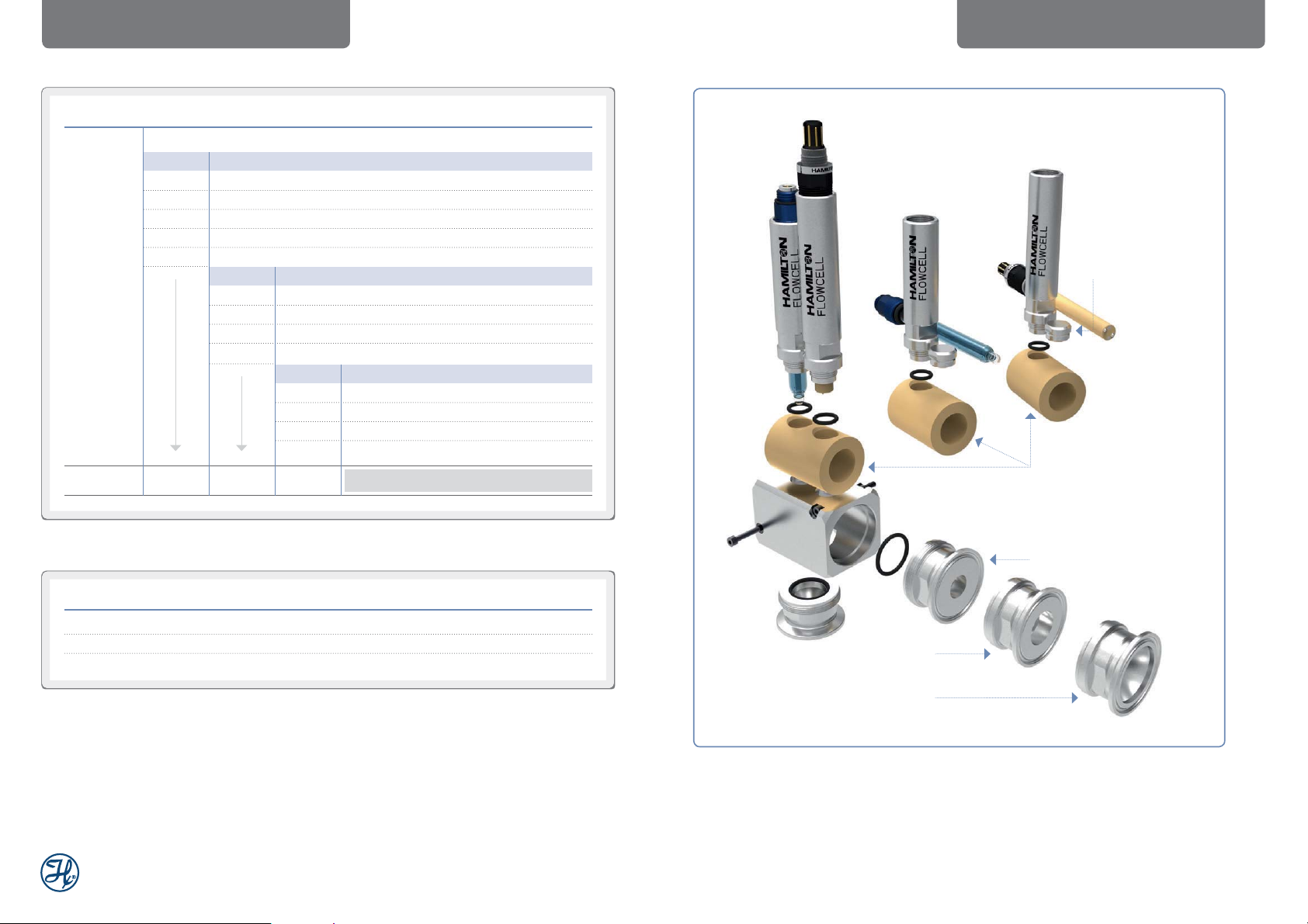
4 Description of the FlowCell
The FlowCell is intended for the professional use in process analytics, as an adapter to mount
sensors with a shaft diameter of 12 mm. It can be mounted into a pipe by means of Triclamp or
Swagelok connectors.
Position 2
Position 1
Compatibility Table for Sensors:
Tube A Tube B
Position 1 pH Sensor Conducell 4USF
Conducell UPW * OxyFerm
VisiFerm
VisiTrace
VisiPro
Position 2 Conducell 4USF
OxyFerm
VisiFerm
VisiTrace
VisiPro
* not for Flowcell 242585 with Swagelok connection
Position 2
Position 1
Figure 1: Components of the
FlowCell 242585 with two sensor tubes
Sensor tube Sensor tube
Blind plug
Fow-through cell Fow-through cell
Connections Connections
Figure 2: Components of the
FlowCell 242585 with one se nsor tube
Figure 3 : Components of the
FlowCell 242590 with two sensor tubes
™
Operating Instructions
Blind plug
Figure 4: Components of the
FlowCell 242590 with one sensor tube
7FlowCell
Page 5

ASSEMBLY
CLEANING AND MAINTENANCE
OPERATION
5 Assembly
5.1 General
Hamilton accepts no responsibility for damage resulting from incorrect assembly work by
third parties.
If a FlowCell is modified, Hamilton does not accept liability and does not provide any further
guarantee for the FlowCell.
5.2 Mounting the FlowCell
The FlowCell should always be mounted in horizontal
position (see picture). It must not be mounted in
vertical position, because this can prevent proper
function of the FlowCell.
The body of the FlowCell can be easily mounted
to the wall or a board with the help of 2 screws
included with the FlowCell.
The FlowCell must be connected by means of
Triclamp or Swagelok connectors. The flow should
always lead from connection 1 to connection 2
(see picture). This way, a minimum volume of air
and selfdraining of the FlowCell is ensured.
Connection 2
6 Operation
In EU countries, initial operation of the FlowCell ist permitted only when it has been verified that
the FlowCell conforms to the requirement of the EU Directive.
Before initial operation of the FlowCell
• Ensure that the seal is tight
• Ensure that all parts are in working order.
In addition to initial operation, perform the above checks:
• After any breakdown
• When the device has been out of use for a long period
• After repairs or maintenance
ATTENTION ! These specifications must not be exceeded:
Process temperature: -10°C to 140°C. Maximum process pressure : 16 bar.
7 Cleaning and
Maintenance
5.3 Assembling the Sensor
Ensure that there is no damage to the sensor or the
FlowCell. Check whether all o-rings (see “Cleaning
and Maintenance”) are in place in the appropriate
grooves and are free of damage.
To avoid any mechanical damage to o-rings on
assembly, they should be lightly greased.
When mounting two sensors, make certain
they are mounted into the correct sensor tube
(see compatibility table in chapter “Description
of the FlowCell”).
Connection 1
Wall mounting hole
Figure 5: Mounting of FlowCell
Direction of flow
When carrying out all maintenance, cleaning and
servicing, the general safety precautions given
in this set of operating instructions must be
observed. Operation safety and life expectancy
of the flow-through cell are both dependent on
appropriate maintenance and servicing, among
other factors.
The FlowCell can be cleaned with standard
cleaning agents. Never use scouring agents
which contain hard particles. Please check the
o-rings regularly. When mounting a new o-ring
take care not to damage the o-ring nut or the
o-ring itself. Otherwise the tightness can no
longer be guaranteed.
™
Operating Instructions
Figure 6 : Cut through FlowCell 242590.
9FlowCell
Page 6

CLEANING AND MAINTENANCE TECHNICAL DATA
All o-rings should be replaced regularly:
Figure 7: FlowCell with marked sensor positions and FlowCell disasse mbled without PEEK inser t.
Position 2
NOTE: The pH sensor
must always be mounted
in position 1.
Position 1
8 Technical Data
Process connection Triclamp or Swagelok
Wetted parts PEEK LSG / FG nature, Stainless Steel 1.4435
Non wetted parts Stainless Steel 1.4305
Standard seals EPDM (FDA approved)
Temperature range -10 – 140 °C
Maximum pressure 0 – 16 bar
Internal volume Ref 242585 approx. 8 mL (only within the Peek cell)
Internal volume Ref 242590 approx. 25 mL (only within the Peek cell)
ATEX approval Conform to DIN EN 13463-1
Figure 8 : Swagelok connector enlarged.
NOTE: An attempt to disassemble the Swagelok connector can lead to leakage of
the FlowCell. Thus, the Swagelok connector must not be disassembled.
™
Operating Instructions
11FlowCell
Page 7

9 Ordering Information
FlowCell
242585
Code Measuring position
1 only Tube A (short)
2 only Tube B (long)
3 Tube A (short) and Tube B (long)
4 2 x Tube B (long)
0 special
Code Pipe Connection
1 ¼” TC25
2
3 ½” TC25
4 Swagelok 6 mm
5 Swagelok 10 mm *)
6 Swagelok ¼”
7 Swagelok
8 Swagelok ½” *)
0 special
Code o-ring material
1 EPDM
2 FFPM (two measuring positions)
3 FFPM (one measuring position)
0 special
3
⁄8” TC25
3
⁄8” *)
ORDERING INFORMATIONORDERING INFORMATION
This is a blind plug and does
not have any sealing function.
If the second sensor tube is
not used, a Sensor Dummy
should be used for proper
sealing.
Tri c lam p 1/ 2” T C2 5
Tri c lam p 3 /8” TC 25
242585 – < Ordercode
*) not self draining
Ref Accessories
237387 O-ring kit FlowCell TC25 (EPDM)
242540 Sensor Dummy 96 (short)
242563 Sensor Dummy 117 (long)
Swagelok 10 mm Swagelok 6 mm
Figure 9 : FlowCell 242585 and connectors.
™
Operating Instructions
Tri c lam p 1/4” TC 25
13FlowCell
Page 8
ORDERING INFORMATION ORDERING INFORMATION
FlowCell
242590
Code Measuring position
1 only Tube A (short)
2 only Tube B (long)
3 Tube A (short) and Tube B (long)
4 2 x Tube B (long)
0 special
Code Pipe Connection
This is a blind plug
and does not have
any sealing function.
If the second sensor
tube is not used,
a Sensor D ummy
should be used for
proper sealing.
1 ¾” TC50
2 1” TC50
3 1.5” TC50 *)
0 special
Code o-ring material
1 EPDM
2 FFPM (two measuring positions)
3 FFPM (one measuring position)
0 special
242590 – < Ordercode
PEEK Insert
*) not self draining
Ref Accessories
237390 O-ring kit FlowCell TC50 (EPDM)
242540 Sensor Dummy 96 (short)
242563 Sensor Dummy 117 (long)
Tri c lam p 1” TC 50
Tri c l amp 1.5 ” T C50
Figure 10: FlowCell 242590 and connectors.
™
Operating Instructions
Tri c lam p 3 /4 ” T C50
15FlowCell
Page 9

INHALTSVERZEICHNIS
1 Einleitung ........................................................................... 18
2 Sicherheitshinweise .......................................................... 18
2.1 Allgemeine Sicherheitshinweise ............................................... 18
2.2 Restrisiko ................................................................................. 19
2.3 Bestimmungsgemässe Verwendung ....................................... 19
2.4 Grundlegende Sicherheitshinweise ......................................... 19
3 Transport und Lagerung ................................................... 20
4 Beschreibung der FlowCell .............................................. 20
5 Montage ............................................................................. 22
5.1 Haftungsausschluss ................................................................ 22
5.2 Montage der FlowCell .............................................................. 22
5.3 Einbau des Sensors ................................................................. 22
6 Betrieb ................................................................................ 23
7 Reinigung und Wartung .................................................... 23
8 Technische Daten .............................................................. 25
9 Bestellinformationen ......................................................... 26
Wichtiger Hinweis
Copyright © 2016 Hamilton Bonaduz AG, Bonaduz Schweiz. Alle Rechte vorbehalten.
Die Reproduktion irgendeines Teils dieses Dokuments in jeder beliebigen Form ist ohne die
ausdrückliche schriftliche Zustimmung der Hamilton Bonaduz AG untersagt.
Der Inhalt dieses Handbuchs kann ohne vorherige Ankündigung geändert werden. Technische Änderungen vorbehalten. Es wurde grösstmögliche Sorgfalt auf die Richtigkeit der Informationen in diesem Handbuch verwendet. Sollten dennoch Fehler entdeckt werden, würde
sich die Hamilton Bonaduz AG freuen, darüber informiert zu werden. Ungeachtet dessen kann
die Hamilton Bonaduz AG keine Haftung für etwaige Fehler in diesem Handbuch oder deren
Folgen übernehmen.
™
Bedienungsanleitung
17FlowCell
Page 10

EINLEITUNG
SICHERHEITSHINWEISE
SICHERHEITSHINWEISE
1 Einleitung
Diese Bedienungsanleitung bezieht sich auf die FlowCell in folgenden Ausführungsformen:
Name Ref
FlowCell TC25 242585-XYZ
FlowCell TC50 242590-XYZ
Hamilton Durchflusszellen sind nach neuesten technischen und wissenschaftlichen Erkenntnissen hergestellte Qualitätsprodukte. Bei genauer Beachtung der nachstehenden Hinweise
erreichen Sie ein Höchstmass an Sicherheit und Lebensdauer.
Diese Betriebsanleitung muss vom zuständigen Personal gelesen, verstanden und beachtet
werden. Für Schäden und Betriebsstörungen, die sich aus Nichtbeachten der Betriebsanleitung
ergeben, übernimmt Hamilton keine Haftung.
2 Sicherheitshinweise
2.1 Allgemeine Sicherheitshinweise
Diese Durchflusszellen sowie deren Ausrüstungsteile sind nach dem neuesten Stand der Technik gebaut und betriebssicher. Dennoch drohen bei Fehlbedienung oder Missbrauch Gefahren
für Leib und Leben des Bedieners.
Die Durchflusszelle ist nur zu benutzen:
• Für die bestimmungsgemässe Verwendung
• In einwandfreiem Zustand
Alle Personen, die mit der Inbetriebnahme, der Bedienung und der Wartung der Durchflusszelle
zu tun haben, müssen die nachfolgenden Hinweise aufmerksam lesen und beachten. Es geht
um Ihre Sicherheit!
2.2 Restrisiko
Auch wenn alle notwendigen Sicherheitsmassnahmen getroffen wurden, besteht ein Restrisiko
durch Undichtigkeiten oder mechanische Schäden an der FlowCell. An defekten Dichtungen
können Gase oder Flüssigkeiten unkontrolliert austreten.
2.3 Bestimmungsgemässe Verwendung
Die FlowCell ist nur für die in Kapitel 6 beschriebenen Betriebsverhältnisse wie Temperatur und
Druck vorgesehen.
Zur bestimmungsgemässen Verwendung gehört auch die Einhaltung der von Hamilton vorgeschriebenen Bedingungen für Montage, Betrieb, Reinigung und Wartung. Für andere oder
darüber hinausgehende Schäden haftet Hamilton nicht.
2.4 Grundlegende Sicherheitshinweise
Installation, Inbetriebnahme, Reinigung, Wartung, Störungsbeseitigung
• Vorgeschriebene Wartungs- und Inspektionsarbeiten müssen in angemessenen Abständen,
wie in Kapitel «Reinigung und Wartung» beschrieben, durchgeführt werden.
• Informieren Sie das Bedienungspersonal vor Beginn der Wartungs- und Instandhaltungsarbeiten.
• Sichern Sie alle der FlowCell vor- und nachgeschalteten Anlageteile und Betriebsmedien
gegen unbeaufsichtigte Inbetriebnahme ab.
• Der Ausbau der Sensoren aus der FlowCell darf nur in drucklosem Zustand erfolgen.
• Mangelhafte Bauteile sofort austauschen. Nur Originalersatzteile verwenden. Bei fremdbezogenen Teilen ist nicht gewährleistet, dass sie den Betriebs- und Sicherheitserfordernissen der
FlowCell genügen.
• Überprüfen Sie nach Beendigung der Wartungsarbeiten, dass das Innere der FlowCell sauber
ist und dass alle Schraubverbindungen fest sitzen.
Der Prozessdruck von 16 bar und die Prozesstemperatur von 140°C darf in keinem Falle überschritten werden.
™
Bedienungsanleitung
19FlowCell
Page 11

TRANSPORT UND LAGERUNG
BESCHREIBUNG DER FLOWCELL
BESCHREIBUNG DER FLOWCELL
3 Transport und Lagerung
Bitte beachten Sie:
• Die Vollständigkeit der Lieferung der FlowCell ist beim Empfang zu prüfen.
• Eventuelle Transportschäden und/oder fehlende Teile sind sofort schriftlich zu melden.
• Bevor Sie eine FlowCell zurückschicken, kontaktieren Sie bitte Hamilton für eine «Return
of Goods Authorisation» (RGA) Nummer. Bitte stellen Sie sicher, dass die FlowCell vor der
Rücksendung gereinigt (dekontaminiert) ist.
• Wenn Sie die FlowCell zu Ihrem Hamilton-Partner oder direkt an Hamilton zurücksenden,
stellen Sie sicher, dass sich die FlowCell in der Originalverpackung befindet.
• Während der Lagerung ist die FlowCell vor Nässe zu schützen.
4 Beschreibung der FlowCell
Die FlowCell ist für den professionellen Einsatz als Adapter in der Prozessmesstechnik zum
Einbau von Sensoren mit 12 mm Schaftdurchmesser vorgesehen. Sie kann in Rohrleitungen
mit Triclamp oder Swagelok Anschlüssen montiert werden.
Position 2
Position 1
Tabelle für den Einbau von Sensoren:
Tube A Tube B
Position 1 pH Sensor Conducell 4USF
Conducell UPW * OxyFerm
VisiFerm
VisiTrace
VisiPro
Position 2 Conducell 4USF
OxyFerm
VisiFerm
VisiTrace
VisiPro
* nicht für FlowCe ll 242585 mit Swagelok Anschluss geeig net
Position 2
Position 1
Bild 1: Bestandteile der FlowCell 242585
mit zwei Einbaurohren
Einbaurohr Einbaurohr
Blindstopfen
Durchflusszelle Durchflusszelle
Anschlüsse Anschlüsse
Bild 2: Bestandte ile der FlowCe ll 242585
mit einem Einbaurohr
Bild 3: Bestandteile de r FlowCell 242590
mit zwei Einbaurohren
™
Bedienungsanleitung
Blindstopfen
Bild 4: Bestandteile der FlowCell 242590
mit einem Einbaurohr
21FlowCell
Page 12

MONTAGE
REINIGUNG UND WARTUNG
BETRIEB
5 Montage
5.1 Haftungsausschluss
Für Schäden infolge unsachgerechter Ausführung der Montagearbeiten durch Fremdpersonal
übernimmt Hamilton keine Haftung. Bei Modifikationen der FlowCell entfällt jegliche Haftung und
Hamilton übernimmt keine Gewährleistung für die FlowCell.
5.2 Montage der FlowCell
Die FowCell sollte immer in horizontaler Position (siehe
Bild) eingebaut werden. In vertikaler Position kann eine
einwandfreie Funktion nicht gewährleistet werden.
Die FlowCell kann sehr einfach mit 2 Schrauben an
einer Wand oder einem Schaltbrett montiert werden.
Die Schrauben liegen der Lieferung bei.
Die FlowCell muss mit Triclamp- oder SwagelokAnschlüssen angeschlossen werden. Der Fluss sollte
immer von Anschluss 1 zu Anschluss 2 fliessen (siehe
Bild). Nur so kann sichergestellt werden, dass ein minimales Volumen an Luft in der Zelle eingeschlossen wird
und die Selbstentleerung funktioniert.
5.3 Einbau des Sensors
Stellen Sie sicher, dass keine Beschädigungen am
Sensor bzw. an der FlowCell vorliegen. Prüfen Sie,
ob alle O-Ringe (siehe «Reinigung und Wartung»)
in den vorgesehenen Nuten vorhanden bzw. nicht
beschädigt sind.
Damit die O-Ringe beim Einbau nicht mechanisch
verletzt werden sind diese leicht mit Fett
einzuschmieren.
Wenn Sie 2 Sensoren gleichzeitig montieren, stellen Sie sicher, dass diese in den richtigen
Einbaurohren eingebaut sind (siehe Tabelle für dem Einbau von Sensoren in Kapitel «Beschreibung der FlowCell»).
Bohru ng für Wandmontage
Bild 5: Befestigung der FlowCell
Anschluss 2
Anschluss 1
Flussrichtung
6 Betrieb
Die Inbetriebnahme der FlowCell ist in den Ländern der EU solange untersagt bis festgestellt
wurde, dass sie den Bestimmungen der EG-Richtlinie Maschinen, den harmonisierten Normen,
Europanormen oder den entsprechenden nationalen Normen entspricht.
Bevor Sie die FlowCell in Betrieb nehmen:
• Stellen Sie sicher, dass die Dichtigkeit gewährleistet ist.
• Stellen Sie sicher, dass alle Teile funktionstüchtig sind.
Die Prüfungen sind auch durchzuführen,
• nach einem Störfall
• nach längerem Stillstand
• nach Reparatur- bzw. Wartungsarbeiten
WARNUNG: Folgende Spezifikationen
dürfen nicht überschritten werden:
Prozesstemperatur: -10 °C bis 140 °C
Maximaler Prozessdruck: 16 bar
7 Reinigung und
Wartung
Bei allen Wartungs-, Reinigungs- und Instandhaltungsarbeiten sind die allgemeinen Sicherheitsanweisungen dieser Betriebsanleitung zu
beachten.
Die Betriebssicherheit und die Lebensdauer der
FlowCell sind neben mehreren Faktoren, wie der
ordnungsgemässen Wartung und der Instandsetzung abhängig.
Die FlowCell kann mit den üblichen Reinigungsmitteln gereinigt werden. Scheuermittel sind
ungeeignet. O-Ringe regelmässig überprüfen.
Werden O-Ringe ersetzt darf die Nut wie auch
der neue O-Ring mecha nisch nicht verletzt
werden, da sonst die Dichtfunktion nicht mehr
gewährleistet werden kann.
Bild 6: Q uerschnit t durch die FlowCell 242590
™
Bedienungsanleitung
23FlowCell
Page 13

REINIGUNG UND WARTUNG TECHNISCHE DATEN
Bild 7: FlowCell mit markie rten Positionen und demontierte FlowCell ohne PEEK-Insert.
Position 2
Position 1
HINWEIS: Der
pH-Sensor muss
immer in Position 1
eingebaut werden.
8 Technische Daten
Prozessanschluss Triclamp oder Swagelok
Medienberührte Teile PEEK LSG / FG natur, Edelstahl 1.4435
Nicht medienberührte Teile Edelstahl 1.4305
Standarddichtungen EPDM (FDA anerkannt)
Temperaturbereich -10 – 140°C
Maximaler Druck 0 – 16 bar
Internes Volumen Ref 242585 ca. 8 mL (nur innerhalb der PEEK-Zelle)
Internes Volumen Ref 242590 ca. 25 mL (nur innerhalb der PEEK-Zelle)
ATEX Zertifizierung Erfüllt DIN EN 13463-1
Bild 8: ve rgrösserte r Swagelok-Anschluss
HINWEIS: Versuchen sich nicht den Swagelok-Anschluss auseinander zu schrauben.
Dies kann zu Undichtigkeiten der FlowCell führen.
™
Bedienungsanleitung
25FlowCell
Page 14

BESTELLINFORMATIONEN BESTELLINFORMATIONEN
9 Bestellinformationen
FlowCell
242585
Code Messposition
1 nur Tube A (kurz)
2 nur Tube B (lang)
3 Tube A (kurz) und Tube B (lang)
4 2 x Tube B (lang)
0 Spezial
Code Rohranschluss
1 ¼” TC25
2
3 ½” TC25
4 Swagelok 6 mm
5 Swagelok 10 mm *)
6 Swagelok ¼”
7 Swagelok
8 Swagelok ½” *)
0 Spezial
Code O-Ring Material
1 EPDM
2 FFPM (zwei Messpositionen)
3 FFPM (eine Messposition)
0 Spezial
3
⁄8” TC25
3
⁄8” *)
Dieser Blindstopfen hat
keine Dichtfunktion. Wenn
das zweite Einbaurohr
nicht benutz t wird, muss
ein Sensor-Dummy für
eine einwandfreie Dichtung
montiert werden.
Tri c lam p 1/ 2” T C2 5
Tri c lam p 3 /8” TC 25
242585 – < Bestellnummer
*) nicht selbstentleerend
Ref Zubehör
237387 O-Ring Kit FlowCell TC25 (EPDM)
242540 Sensor Dummy 96 (kurz)
242563 Sensor Dummy 117 (lang)
Swagelok 10 mm Swagelok 6 mm
Bild 9: FlowCell 242585 mit Anschlüssen
™
Bedienungsanleitung
Tri c lam p 1/4” TC 25
27FlowCell
Page 15
BESTELLINFORMATIONEN BESTELLINFORMATIONEN
FlowCell
242590
Code Messposition
1 nur Tube A (kurz)
2 nur Tube B (lang)
3 Tube A (kurz) und Tube B (lang)
4 2 x Tube B (lang)
0 Spezial
Dieser Blindstopfen
hat keine Dichtfunktion. Wenn das zweite
Einbaurohr nicht
benut zt wird, muss ein
Sensor-Dummy für eine
einwandfreie Dichtung
montiert werden.
Code Rohranschluss
1 ¾” TC50
2 1” TC50
3 1.5” TC50 *)
0 Spezial
Code O-Ring Material
1 EPDM
2 FFPM (zwei Messpositionen)
3 FFPM (eine Messposition)
0 Spezial
242590 – < Bestellnummer
PEEK-Insert
*) nicht selbstentleerend
Ref Zubehör
237390 O-Ring Kit FlowCell TC50 (EPDM)
242540 Sensor Dummy 96 (kurz)
242563 Sensor Dummy 117 (lang)
Tri c lam p 1” TC 50
Tri c l amp 1.5 ” T C50
Bild 10: FlowCell 242590 mit Anschlüssen
™
Bedienungsanleitung
Tri c lam p 3 /4 ” T C50
29FlowCell
Page 16

NOTIZENNOTES
™
Bedienungsanleitung
31FlowCell
Page 17

© 2016 Hamilton Bonaduz AG. All rights reserved.
624521/01 —
03/2016
Web: www.hamiltoncompany.com
Hamilton Americas & Pacific Rim
4970 Energy Way
Reno, Nevada 89502 USA
Tel: +1-775-858-3000
Fax: +1-775-856-7259
sales@hamiltoncompany.com
Hamilton Europe, Asia & Africa
Via Crusch 8
CH-7402 Bonaduz, Switzerland
Tel: +41-58-610-10-10
Fax: +41-58-610-00-10
contact.pa.ch@hamilton.ch
USA: 800-648-5950
Europe: +41-58-610-10-10
To find a representative in your area, please visit www.hamiltoncompany.com.
This guide may be available in other languages. Visit www.hamiltoncompany.com for more information.
 Loading...