

Hamilton Conducell 4US, Conducell 4US-T150-50, Conducell 4US-G125, Conducell 4US-T150-100 Operating Instructions Manual
Page 1

Conducell™ 4US Sensors
Operating Instructions
Bedienungsanleitung
Page 2

Important note
Reproduction of any part of this manual in any form whatsoever without the express written
consent of Hamilton Bonaduz AG is forbidden. The contents of this manual are subject to
change without notice. Technical changes reserved.
TABLE OF CONTENTS
Table of Contents
1 Liability ................................................................................. 4
2 Intended use ........................................................................ 5
3 Safety ................................................................................... 5
4 Initial operation .................................................................... 5
5 Electrical wiring ................................................................... 6
6 Assembly ............................................................................. 8
7 Diagrams with dimensions ................................................. 9
8 Calibration ......................................................................... 10
9 Measurement......................................................................11
10 Cleaning ..............................................................................11
11 Dispo s a l ..............................................................................11
12 Technical data ................................................................... 12
13 Instructions for use in potentially
explosive atmospheres ..................................................... 13
14 Connection to transmitter ................................................ 14
15 Accessories ....................................................................... 15
All efforts have been made to ensure the accuracy of the contents of this manual. However,
should any errors be detected, Hamilton Bonaduz AG would greatly appreciate being informed
of them. The above notwithstanding, Hamilton Bonaduz AG can assume no responsibility for
any errors in this manual or their consequences.
Copyright © 2019 Hamilton Bonaduz AG, Bonaduz Switzerland. All rights reserved.
™
4US Sensors Operating Instructions
3Conducell
Page 3

INTENDED USE • SAFETY • INITIAL OPERATIONLIABILITY
Operating Instructions
These operating instructions are intended for the Hamilton Conducell 4US sensors.
Ref Description Thread ATEX
1
237700-OP Conducell 4US-G125 G 1
237750 Conducell 4US-T150-50 Triclamp 1.5”
237760 Conducell 4US-T150-100 Triclamp 1.5”
Hamilton Conducell 4US sensors are quality products manufactured with the latest technology.
These instructions should be read, understood and followed by all staff using the device.
Hamilton can assume no responsibility for damage and operational disruptions arising from
failure to observe these instructions.
1 Liability
The Liability of Hamilton Bonaduz AG is detailed in the document «General Terms and Conditions
of Sale and Delivery (GTS)», chapter 12.
Hamilton is expressly not liable for direct or indirect losses arising from use of the sensors. It
must in particular be insured in this conjunction that malfunctions can occur on account of the
inherently limited useful life of sensors contingent upon their relevant applications. The user is
responsible for the calibration, maintenance and regular replacement of the sensors. In the case
of critical sensor applications, Hamilton recommends using back-up measuring points in order
to avoid consequential damages. The user is responsible for taking suitable precautions in the
event of a sensor failure.
⁄4”
2 Intended use
With the Conducell 4US line, Hamilton has developed a family of in-line conductivity sensors
which perform under demanding conditions in biotechnology and the general chemical industry.
During development, special attention was paid to an optimum sanitary design. All materials in
contact with the solution are FDA approved.
The sensors are based on the 4-electrode principle which excludes polarization phenomena
normally observed with 2-electrode sensors. The engineered design guarantees an excellent
linearity over a conductivity range of more than 6 decades.
3 Safety
This sensor is to be used only as intended and is to be kept in a condition that ensures complete safety. The specifications given in the section «Technical Data» as regards temperature,
pressure etc. may under no circumstances be exceeded.
Inappropriate use or misuse can be dangerous.
Assembly and maintenance may only be done by trained personnel.
During assembly, ensure that the positioning is correct and that the O-ring is undamaged.
O-rings are consumable items and must be replaced regularly – at least once a year.
The built-in temperature sensor should only be used for compensation of conductivity, not for
controlling the process temperature.
Conducell 4US sensors are used to determine electrolyte conductivity in solutions. If these
sensors are used in potentially explosive atmospheres, see the section «Instructions for use in
potentially explosive atmospheres».
Every product for shipment or sent back for repair must be decontaminated. If working with
hazardous liquids observe and carry out the maintenance procedures, paying particular attention to cleaning and decontamination. If the product becomes contaminated with biohazardous,
radioactive or chemical material, it should be cleaned.
4 Initial operation
This Conducell 4US sensor has been carefully tested and is ready for use. During unpacking,
please check for any mechanical defects. In case of a complaint please return the Conducell
4US in its original packing to Hamilton and describe the problem.
™
4US Sensors Operating Instructions
5Conducell
Page 4

5 Electrical wiring
ELECTRICAL WIRINGELECTRICAL WIRING
Signal description Cable Conducell 4US
Pt1000 (low end) Grey
Pt1000 (low end) White
Pt1000 (high end) Blue
Current electrode (high end) Pink
Potential electrode (high end) Green
Potential electrode (low end) Brown
Current electrode (low end) Yellow
Not connected on sensor Shield
Not connected Red
Conducell Hamilton Knick Knick Stratos Knick Stratos e
4US H100 Cond Cond 2201 X 2401 Cond 2402 / 2405 Cond
Grey D 7 6 D
White D 7 6 D
Blue E 8 5 E
Pink 1 1 1 1
Green 2 2 2 2
Brown 3 3 3 3
Yellow 4 4 4 4
Shield C 5 5 C
Red - - - Comment Short 4 and 5 Short 4 and 5 Short 4 and 5 Short 4 and 5
Conducell 4US Emerson Yokogawa SIEMENS
5081 C Model SC150, SC202, SIPAN
SC402, SC450 32/32X
Grey 3 11 23
White 4 11 24
Blue 5 12 25
Pink 8 14 26
Green 11 13 29
Brown open 15 27
Yellow open 16 30
Shield 5 63 Shield
Red - - Comment 2-electrode arrangement *
* For Yokogawa SC150, SC202, SC402, SC450 please be aware that the measuring
range must stay within the specified input range of the instrument.
ATTENTION! The linearity of the system is strongly dependent on the instrument to which the sensor is attached. For applicable measuring range refer to
Technical Specifications of the manufacturer of the instrument.
™
4US Sensors Operating Instructions
7Conducell
Page 5
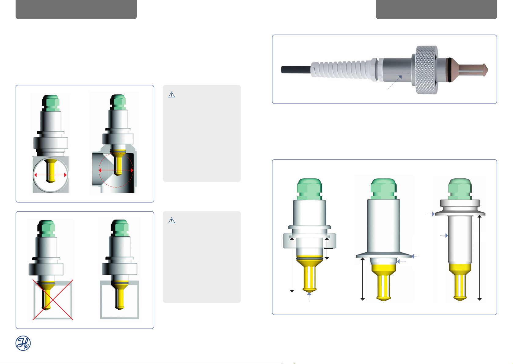
6 Assembly
Please check if the process connection is sufficiently clean. Then fit the Conducell 4US.
Please follow the instructions mentioned below.
Examples:
DIAGRAMS WITH DIMENSIONSASSEMBLY
Ø 60mm
min
ATTENTION! The cell
constant and the linearity
of the sensor can vary
with the fitting situation.
A symmetrical setup is
recommended. Leave an
open space of 60 mm
minimum diameter.
Partitions made of
non-conductive material
should preferably be
used.
ATTENTION!
A symmetrical setup is
recommended in order to
ensure a high degree of
linearity. To achieve high
precision the cell constant should be calibrated
in the final setup. Make
sure that all 4 electrodes
are completely and
continuously immersed in
the measuring sample.
Position marker
If the sensor is dismounted, the position marker helps to remount it in the original position.
7 Diagrams with dimensions
E = H + 37
Ø 50.5
Ø 24
H*
50
Ø 50.5
Ø 24
97
Ø 13
* H = O-ring position ( 22 mm ≤ OP ≤ 55 mm)
™
4US Sensors Operating Instructions
9Conducell
Page 6

MEASUREMENT • CLEANING • DISPOSALCALIBRATION
8 Calibration
There are two possibilities for calibration:
1) Calibration while sensor is disassembled from process:
• First, rinse the sensor thoroughly with deionized water.
• Use a beaker or container that has an (internal) diameter of at least 30 mm. (Conducell
4US fits perfectly into the Hamilton Conductivity Standards, and can be calibrated directly
in the bottle.)
• Use a solution of known conductivity. Check the temperature table of the conductivity
standard.
• Immerse the lower part of the sensor in the standard. Make sure that the 4 electrodes are
completely immersed. The sensor should be placed in the center of the beaker.
• Leave the sensor for at least 5 minutes for equilibration, before initiating the calibration on the
instrument.
For precise determination of the cell constant, it is recommended that you use an assembly
situation similar or equal to the situation in the process. The cell constant may vary with the
assembly situation.
2) Calibration in the process:
• Insert the sensor in the process.
• Leave conductivity and temperature at least 15 min. for equilibration.
• Take a process sample and perform an external measurement with a reference conductivity
system. The best approach is to perform the measurement at a temperature equal to that
of the process. If this is not possible, you need to know the temperature coefficient of your
sample (similar to temperature table on Hamilton Conductivity Standards bottle).
• Manually adjust the cell constant to read the same conductivity value on the process
instrument.
• You may switch off the temperature compensation of the process and the laboratory instruments to prevent any errors.
9 Measurement
Air/gas bubbles may stick to the sensitive area of the sensor. As a consequence, the measurement value might be wrong. In case of a shutdown of the power supply (230V) the measurement value could be wrong.
10 Cleaning
Conducell 4US can be cleaned with standard cleaning agents. Never use scouring agents
which contain hard particles. Please check the O-rings from time to time. When mounting the
new O-ring take care not to damage the O-ring nut or the O-ring itself. Otherwise the tightness
of seal can no longer be guaranteed.
If working with hazardous liquids observe and carry out the maintenance procedures, paying
particular attention to cleaning and decontamination.
Cleaning, assembly and maintenance should be performed by personnel trained in such work.
Do not use any abrasive tissues or cleaning materials and do not use any cleaning chemicals
other then described above. Before removing the sensor from the measuring setup, always
make sure that the setup is pressure-less and cold and that no process medium can be accidentally spilled. When removing and cleaning the sensor, it is recommended to wear safety
glasses and protective gloves.
11 Disposal
The design of Hamilton sensors minimizes environmental impact. According to the
EU directive 2002/96/EC the Hamilton sensors should be disposed as waste of
electrical and electronic equipment, and not in municipal waste, or it can be sent
back to Hamilton for disposal.
有害物質表,請參閱 www.hamiltoncompany.com
章節過程分析,符合性聲明
™
4US Sensors Operating Instructions
11Conducell
Page 7
TECHNICAL DATA
INSTRUCTIONS FOR USE IN POTENTIALLY
EXPLOSIVE ATMOSPHERES
12 Technical data
Measuring Range 0.1 μS/cm to 500 mS/cm
Linearity (relative) ± 0.5 - 5 %
Cell constant 0.147 cm-1
Process Temperature -20 to 135 °C
Pressure Range 0 to 6 bar
Temperature Sensor Pt1000
Wetted Parts PEEK (FDA approved), Stainless Steel DIN 1.4435,
EPDM (FDA approved)
Surface Quality of Steel Ra < 0.4 μm (N5)
O-ring Material EPDM (FDA approved)
Process Connection G125: G 1-1/4” / T150: Triclamp 1.5”
Electrical Connector 5 m Open End
1) Uncertainty of ± 5 % arise when using only ONE single cell constant for the full range. ± 0.5% accuracy can be
achieved when calibration is performed in a conductivity range close to that of the sample. Remember also that
linearity is strongly influenced by the transmitter used.
2) Individual cell constant measured with Hamilton standard procedure printed on the label. The cell constant is
influenced by the assembly situation.
1)
2)
13 Instructions for use in potentially explosive atmospheres
ATEX / IECEx marking:
Gas: CE 0035
Dust: CE 0035
Manufacturer: Hamilton Bonaduz AG, 7402 Bonaduz, Switzerland
EC type examination report: TÜV 03 ATEX 7005 X
IECEx certificate of conformity: IECEx TUR 14.0001 X
EC type examination report and IECEx certificate of conformity can be downloaded from
www.hamiltoncompany.com.
The conditions described in the ATEX / IECEx certificate must be respected.
ATTENTION! In case a gas atmosphere and a dust atmosphere are or could
be present at the same time, the risk of explosion must be examined carefully
and special precautions may be necessary.
Assembly
1) The operator of equipment in potentially explosive atmospheres is responsible for ensuring
that all components of the system are certified for that area classification and are compatible
with each other.
II 1/2 G Ex ia IIB T4/T5/T6 Ga/Gb
II 1/2 D Ex ia IIIC T x °C Da/Db
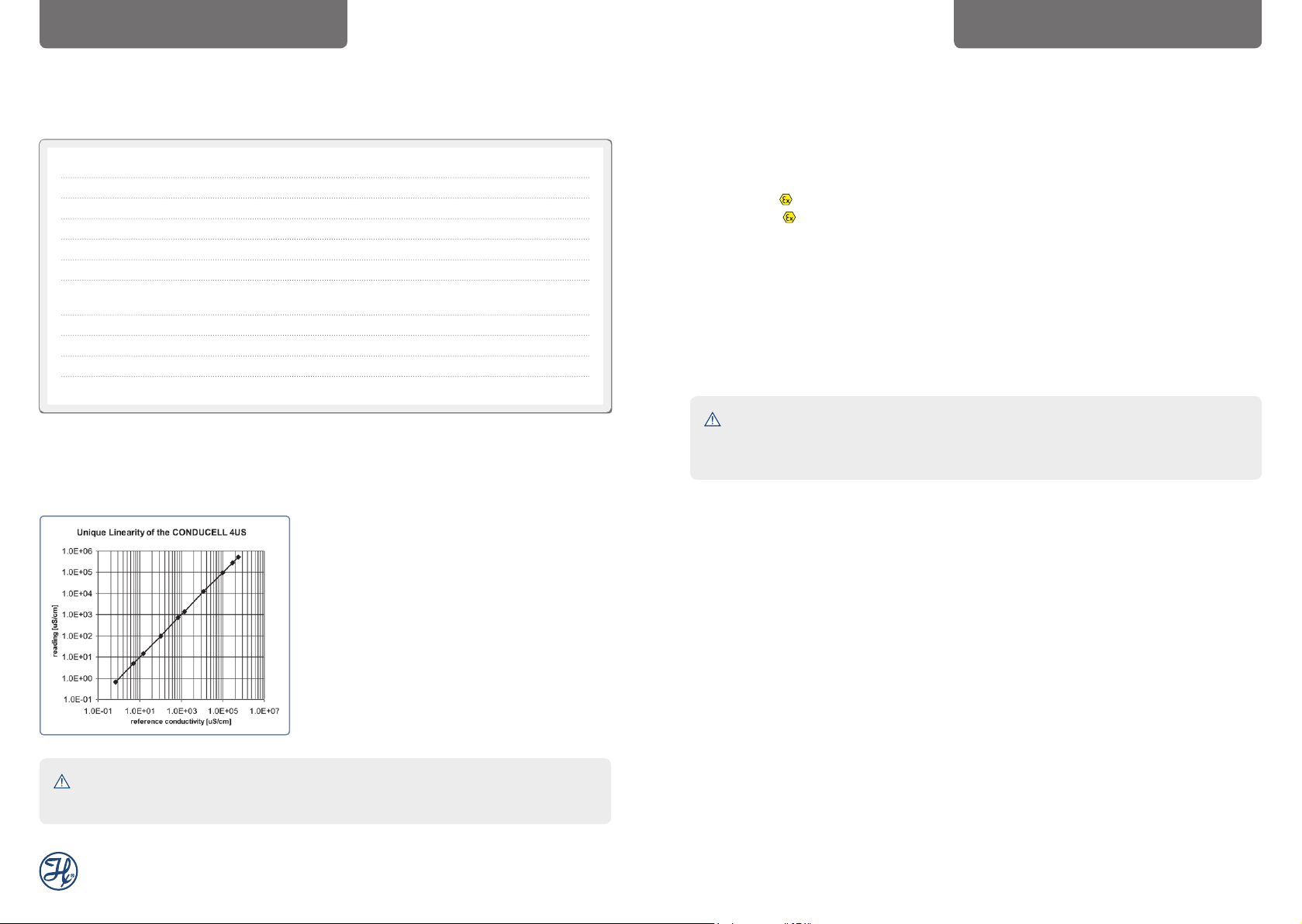
Fig. 1: Linearity of the Conducell 4US, connected to a typical
process transmit ter. One single cell constant determined at
1413 μS/cm was used over the full range.
ATTENTION! The linearity of the system is strongly dependent on the
transmitter connected to the sensor.
2) In gas atmospheres, the Ex approval is not dependent on any conditions regarding mounting of the sensor. In dust atmospheres, however, special restrictions may apply when using
armatures made of plastic material.
3) O-rings having a sealing function between Ex-zone 0 and 1 or Ex-zone 20 and 21, respectively,
must be replaced at each dismantling of the sensor.
4) Sensors, transmitter and equipment required are to be set up within one balanced potential
system.
5) When the sensor is assembled, the ATEX / IECEx sticker is to be attached to the cable in an
easily visible place, as near as possible to the sensor itself. This sticker is to indicate that an
ATEX / IECEx approved sensor is in use. The sticker should not be removed at any time.
™
4US Sensors Operating Instructions
13Conducell
Page 8

ACCESSORIESCONNECTION TO TRANSMITTER
14 Connection to transmitter
Conducell 4US is suitable for connection to an intrinsically safe electrical circuit with protection
level ia. The operator of the equipment must ensure that the allowable electrical values for the
sensor all exceed those for the transmitter. None of the values cited for electrical power, voltage
and current may be exceeded in sum (measurement and temperature circuit together). Electric
values for Conducell 4US are as follows:
U = 24 V; I = 173 mA; P: Function of process temperature. The maximum allowable electric
power P of the transmitter (measurement and temperature circuit together) depends on the
desired process temperature.
For gas atmospheres:
Typ e 6 P ≤ 50 mW P ≤ 100 mW P ≤ 150 mW
T4 109°C 91°C 72°C
T5 74°C 56°C 37°C
T6 59°C 41°C 22°C
For dust atmospheres:
Table for the calculation of the maximum surface temperature «x» of the sensor as a function of
the maximum electrical power of the transmitter «P
«x» has to be smaller than the ignition temperatures of dust involved.
» and ambient/process temperatures «Ta».
i
15 Accessories
Conductivity standards
Value at 25°C Accuracy Stability Certified Package Ref
(month) by
1.3 μS/cm 1% 12 DFM Glass bottle 300 mL 238973
5 μS/cm 1% 36 DFM Glass bottle 300 mL 238926
15 μS/cm 1% 36 DFM Glass bottle 300 mL 238927
84 μS/cm 1% 18 DFM 1 Calpack bottle 500 mL 238984
100 μS/cm 1% 36 DFM Glass bottle 300 mL 238934
147 μS/cm 1% 18 DFM 1 Calpack bottle 500 mL 238985
706 uS/cm 2% 36 Hamilton Glass bottle 300 mL 238929
1413 μS/cm 1% 36 DFM Glass bottle 300 mL 238928
1413 μS/cm 1% 18 DFM 1 Calpack bottle 500 mL 238986
12880 μS/cm 1% 18 DFM 1 Calpack bottle 500 mL 238988
100 mS/cm 1% 24 Hamilton Glass bottle 300 mL 238935
Typ e Pi ≤ 50 mW Pi ≤ 100 mW Pi ≤ 15 0 mW
6 x = T
Ta: ambient / process temperature
+ 21°C x = Ta + 39°C x = Ta + 58°C
a
The temperature limit stated on the sensor must always be respected.
™
4US Sensoren Bedienungsanleitung
15Conducell
Page 9

Wichtiger Hinweis
Die Reproduktion irgendeines Teils dieses Handbuchs in jeder beliebigen Form ist ohne die ausdrückliche schriftliche Zustimmung der Hamilton Bonaduz AG untersagt. Der Inhalt dieses Handbuchs kann ohne vorherige Ankündigung geändert werden. Technische Änderungen vorbehalten.
INHALTSVERZEICHNIS
Inhaltsverzeichnis
1 Haftung .............................................................................. 18
2 Bestimmungsgemässe Verwendung ............................... 19
3 Sicherheitshinweise .......................................................... 19
4 Inbetriebnahme ................................................................. 20
5 Elektrische Anschlüsse .................................................... 20
6 Einbau des Leitfähigkeitssensors .................................... 22
7 Masszeichnungen ............................................................. 23
8 Kalibration .......................................................................... 24
9 Messung ............................................................................ 25
10 Reinigung ........................................................................... 25
11 Entsorgung ........................................................................ 25
12 Technische Daten .............................................................. 26
13 Hinweise für den Einsatz in
explosionsgefährdeten Bereichen ................................... 27
14 Anschluss an Transmitter ................................................. 28
15 Zubehör .............................................................................. 29
Es wurde grösstmögliche Sorgfalt auf die Richtigkeit der Informationen in diesem Handbuch
verwendet. Sollten dennoch Fehler entdeckt werden, würde sich die Hamilton Bonaduz AG
freuen, darüber informiert zu werden. Ungeachtet dessen kann die Hamilton Bonaduz AG keine
Haftung für etwaige Fehler in diesem Handbuch oder deren Folgen übernehmen.
Copyright © 2019 Hamilton Bonaduz AG, Bonaduz Schweiz. Alle Rechte vorbehalten.
™
4US Sensoren Bedienungsanleitung
17Conducell
Page 10

HAFTUNG
BESTIMMUNGSGEMÄSSE VERWENDUNG
SICHERHEITSHINWEISE
Bedienungsanleitung
Diese Bedienungsanleitung bezieht sich auf die Hamilton Conducell 4US Sensoren.
Ref Beschreibung Anschluss ATEX
1
237700-OP Conducell 4US-G125 G 1
237750 Conducell 4US-T150-50 Triclamp 1.5”
237760 Conducell 4US-T150-100 Triclamp 1.5”
Hamilton Leitfähigkeitssensoren sind nach neuesten Erkenntnissen hergestellte Qualitätsprodukte.
Diese Betriebsanleitung muss vom zuständigen Personal gelesen, verstanden und beachtet
werden. Für Schäden und Betriebsstörungen, die sich aus Nichtbeachten der Betriebsanleitung
ergeben, übernimmt die Firma Hamilton keine Haftung.
1 Haftung
Die Haftung der Hamilton Bonaduz AG wird in Kapitel 12 der «Allgemeine Verkaufs- und Lieferbedigungen (AVB)» geregelt.
Hamilton haftet insbesondere nicht für direkte oder indirekte Schäden, die sich aus der Nutzung
der Sensoren ergeben. Insbesondere ist hier zu beachten, dass Fehlfunktionen durch die naturgemäss applikativ beschränkte Lebensdauer von Sensoren auftreten können. Der Benutzer ist
für Kalibration, Wartung und den rechtzeitigen Austausch der Sensoren verantwortlich. Bei kritischen Anwendungen der Sensoren empfiehlt Hamilton redundante Messstellen, um Folgeschäden zu vermeiden. Die Einrichtung geeigneter Absicherungen für den Fall eines Sensorausfalles
obliegt dem Anwender.
⁄4”
2 Bestimmungsgemässe Verwendung
Mit der Conducell 4US Linie hat Hamilton in-line Leitfähigkeitssensoren entwickelt, welche den
strengen Anforderungen in der Biotechnologie und in der chemischen Industrie gewachsen
sind. Sie werden für die Bestimmung der elektrolytischen Leitfähigkeit in Lösungen verwendet.
Spezielle Aufmerksamkeit während der Entwicklung hat das hygienische Design erhalten. Alle
Materialien, welche in Kontakt mit der Messlösung kommen sind FDA geprüft.
Die Sensoren sind auf dem 4-Pol Prinzip aufgebaut, welches Polarisierungsphänomene, wie sie
bei einer 2-Pol Zelle auftauchen, ausschliesst. Dieses Prinzip garantiert eine exzellente Linearität
über den ganzen Linearitätsbereich von 6 Dekaden!
3 Sicherheitshinweise
Dieser Sensor ist nur zu benutzen für die bestimmungsgemässe Verwendung und in sicherheitstechnisch einwandfreiem Zustand. Die Spezifikationen bezüglich Druck und Temperatur müssen eingehalten werden (Siehe technische Informationen). Bei Fehlbedienung oder
Missbrauch drohen Gefahren. Montage und Wartung dürfen nur durch geschultes Personal
vorgenommen werden.
Beim Einbau muss auf die korrekte Position und auf einwandfreien Zustand des O-Rings
geachtet werden. O-Ringe sind Verschleissteile, die regelmässig gewechselt werden müssen,
spätestens nach einem Jahr.
Der integrierte Temperaturfühler soll nur für die Kompensation der Leitfähigkeit verwendet
werden und nicht für die Steuerung der Prozesstemperatur.
Die Conducell 4US Sensoren werden eingesetzt zur Bestimmung der elektrolytischen Leitfähigkeit in Lösungen. Werden die Sensoren in explosionsgefährdeten Zonen eingesetzt, so
müssen die Hinweise im Kapitel «Hinweise für den Einsatz in explosionsgefährdeten Bereichen» beachtet werden.
Jedes Produkt das verschickt oder zurück zur Reparatur geschickt wird muss dekontaminiert
werden. Wird mit gefährlichen Flüssigkeiten gearbeitet, muss bei Wartungsarbeiten speziell
auf die Reinigung und Dekontaminierung geachtet werden. Wenn das Produkt mit biologisch
gefährlichen-, radioaktiven- oder chemischen Substanzen kontaminiert, dann muss es gereinigt
werden.
™
4US Sensoren Bedienungsanleitung
19Conducell
Page 11

INBETRIEBNAHME
ELEKTRISCHE ANSCHLÜSSE
ELEKTRISCHE ANSCHLÜSSE
4 Inbetriebnahme
Überprüfen Sie den Sensor beim Auspacken auf eventuelle Schäden. Beanstandete Sensoren
sind Hamilton in der Originalverpackung einzusenden.
5 Elektrische Anschlüsse
Signalbeschreibung Kabel Conducell 4US
Pt1000 (negativ) Grau
Pt1000 (negativ) Weiss
Pt1000 (positiv) Blau
Stromführende Elektrode (positiv) Rosa
Spannungsabgriff (positiv) Grün
Spannungsabgriff (negativ) Braun
Stromführende Elektrode (negativ) Gelb
Nicht angeschlossen am Sensor Schirm
Nicht angeschlossen Rot
Conducell 4US Emerson Yokogawa SIEMENS
5081 C Model SC150, SC202, SIPAN
SC402, SC450 32/32X
Grau 3 11 23
Weiss 4 11 24
Blau 5 12 25
Rosa 8 14 26
Grün 11 13 29
Braun offen 15 27
Gelb offen 16 30
Schirm 5 63 Schirm
Rot - - Kommentar 2-Elektroden Anordnung *
* Bitte be achten Sie für Yokogawa SC150, SC202, SC402, SC450 dass der Messbereich
der Eingangsspezifikation des Gerätes entspricht.
ACHTUNG! Die Linearität des Systems hängt stark vom Instrument ab, an
welches der Sensor angeschlossen ist. Beachten Sie die technischen Spezifikationen des Instrumentenherstellers für den geeigneten Messbereich.
Conducell Hamilton Knick Knick Stratos Knick Stratos e
4US H100 Cond Cond 2201 X 2401 Cond 2402 / 2405 Cond
Grau D 7 6 D
Weiss D 7 6 D
Blau E 8 5 E
Rosa 1 1 1 1
Grün 2 2 2 2
Braun 3 3 3 3
Gelb 4 4 4 4
Schirm C 5 5 C
Rot - - - Kommentar 4 + 5 brücken 4 + 5 brücken 4 + 5 brücken 4 + 5 brücken
™
4US Sensoren Bedienungsanleitung
21Conducell
Page 12

6 Einbau des Leitfähigkeitssensors
Bitte kontrollieren Sie, dass die Prozessverbindung sauber ist. Montieren der Conducell 4US
und befestigen. Bitte beachten Sie die untenstehenden Instruktionen.
Beispiele:
MASSZEICHNUNGENEINBAU DES LEITFÄHIGKEITSSENSORS
Ø 60mm
min
ACHTUNG! Die
Zellenkonstante und die
Linearität kann je nach
Einbausituation variieren.
Ein symmetrischer
Einbau wird empfohlen.
Lassen Sie ein Feld von
mindestens 60 mm
Durchmesser offen.
Verwenden Sie vorzugsweise Wandungen aus
nicht leitfähigem Material.
ACHTUNG!
Um die Linearität zu
gewährleisten wird ein
symmetrischer Einbau
empfohlen. Um eine
hohe Präzision zu
erreichen, sollte die
Zellkonstante im Endaufbau bestimmt werden.
Stellen Sie sicher, dass
alle 4 Elektroden komplett und stetig in der zu
messenden Lösung
eingetaucht sind.
Positionsmarkierung
Die Positionsmarkierung hilft dabei, sicherzustellen, dass ein Sensor immer die gleiche
Einbaulage hat.
7 Masszeichnungen
E = H + 37
Ø 50.5
Ø 24
H*
50
Ø 13
Ø 50.5
Ø 24
97
* H = O-Ring Position ( 22 mm ≤ OP ≤ 55 mm)
™
4US Sensoren Bedienungsanleitung
23Conducell
Page 13

KALIBRATION
MESSUNG • REINIGUNG • ENTSORGUNG
8 Kalibration
Es gibt zwei Möglichkeiten zu kalibrieren:
1) Kalibrierung ausserhalb des Prozesses:
• Zuerst den Sensor gründlich mit deionisiertem Wasser spülen.
• Benützen Sie einen Becher mit einem Minimum Innendurchmesser von 30mm.
(Die Conducell 4US passt in ein Hamilton Leitfähigkeitsstandard und kann direkt in der
Flasche kalibriert werden.)
• Brauchen Sie eine Lösung mit einem bekannten Leitfähigkeitsmesswert. Kontrollieren Sie die
Temperaturtabelle auf dem Leitfähigkeitsstandard.
• Tauchen Sie den unteren Teil des Sensors in die Lösung ein. Stellen Sie sicher, dass
die 4 Elektroden komplett eingetaucht sind. Der Sensor sollte in der Mitte des Bechers
platziert sein.
• Lassen Sie den Sensor für mindestens 5 Minuten in der Messlösung stehen, bis das Gleichgewicht erreicht ist, und starten Sie erst danach die Kalibrierung am Instrument.
Für eine präzise Bestimmung der Zellkonstante, sollte der Sensor in einer gleichen oder ähnlichen
Situation wie im Prozess eingebaut werden. Die Zellkonstante ist von der Einbausituation abhängig.
2) Kalibrierung im Prozess:
9 Messung
Stellen Sie sicher, dass keine Luft- oder Gasblasen an messsensiblen Teilen des Sensors
vorhanden sind. Mögliche Folgen könnten falsche Messwerte sein. Bei einer Abschaltung der
Stromversorgung (230V), könnte der Messwert falsch sein.
10 Reinigung
Die Conducell 4US kann mit den üblichen Reinigungsmitteln gereinigt werden. Scheuermittel
sind ungeeignet. Von Zeit zu Zeit sollten die O-Ringe überprüft werden. Beim Ersatz beschädigter O-Ringe darf die Nut wie auch der neue O-Ring mechanisch nicht verletzt werden, da
sonst die Dichtfunktion nicht mehr gewährleistet ist.
Wird mit gefährlichen Flüssigkeiten gearbeitet, muss bei Wartungsarbeiten speziell auf die Reinigung und Dekontaminierung geachtet werden. Reinigung, Montage und Wartung muss von
trainiertem Personal ausgeführt werden. Verwenden Sie nicht abrasive Tücher oder Reinigungsmaterialien oder andere Reinigungsmittel als diejenigen oben beschrieben. Bevor der Sensor
aus dem Prozess entfernt wird, muss sichergestellt werden, dass der Prozess drucklos und
abgekühlt ist und dass kein Prozessmedium fälschlicherweise verschüttet werden kann.
Wird ein Sensor aus dem Prozess entfernt, muss eine Schutzbrille und Handschuhe getragen
werden.
• Montieren Sie den Sensor im Prozess.
• Lassen Sie den Sensor stabilisieren für mindestens 15 min.
• Nehmen Sie ein Prozessmuster und machen Sie eine externe Referenzmessung. Das beste
Messergebnis erhalten Sie, wenn die Messung bei der gleicher Temperatur durchgeführt wird
wie im Prozess. Sollte das nicht möglich sein, muss der Temperaturkoeffizient der Messlösung
bekannt sein.
• Manuell die Zellkonstante verstellen, damit der gleiche Leitfähigkeitswert am Prozessinstrument abgelesen wird (ähnlich wie auf der Temperaturtabelle auf den Hamilton Leitfähigkeitsstandards).
• Sie können die Temperaturkompensation am Prozess- und Laborinstrument ausschalten, um
Fehler zu vermeiden.
11 Entsorgung
Das Design der Hamilton Sensoren berücksichtigt bestmöglichst die Umweltverträglichkeit. Gemäss der EU Richtlinie 2002/96/EG müssen Hamilton Sensoren einer ge-
trennten Sammlung für Elektro- und Elektronikgeräten zugeführt werden oder können
an Hamilton zur Entsorgung geschickt werden. Sie dürfen nicht dem unsortierten Siedlungsabfall zugeführt werden.
™
4US Sensoren Bedienungsanleitung
25Conducell
Page 14

TECHNISCHE DATEN
EXPLOSIONSGEFÄHRDETEN BEREICHEN
HINWEISE FÜR DEN EINSATZ IN
12 Technische Daten
Messbereich 0.1 μS/cm bis 500 mS/cm
Linearität (relativ) ± 0.5 - 5 %
Zellkonstante 0.147 cm-1
Temperaturbereich -20 bis 135 °C
Druckbereich 0 bis 6 bar
Temperatursensor Pt1000
Medienberührende Materialien PEEK (FDA geprüft), Edelstahl DIN 1.4435,
EPDM (FDA geprüft)
Oberflächenqualität Ra < 0.4 μm (N5)
O-Ring Material EPDM (FDA geprüft)
Prozessanschluss G125: G 1-1/4” / T150: Triclamp 1.5”
Elektrischer Anschluss 5 m offenes Ende
1) Unsicherheiten von ± 5 % entstehen, wenn eine Zellkonstante über den ganzen Bereich verwe ndet wird.
± 0.5% Genauigkeiten können erzielt werden, wenn der Messwert der Kalibrierung nahe am Leitfähigkeits
messwer t des Musters liegt. Beachten Sie, dass die Linearität stark vom verwendeten Instrument abhängig ist.
2) Zellkonstante wird von der Einbausituation bee influsst.
1)
2)
13 Hinweise für den Einsatz in explosionsgefährdeten Bereichen
ATEX / IECEx Kennzeichnung:
Gas: CE 0035
Staub: CE 0035
Hersteller: Hamilton Bonaduz AG, CH-7402 Bonaduz, Switzerland
EG-Baumusterprüfbescheinigung: TÜV 03 ATEX 7005 X
IECEx Certificate of Conformity: IECEx TUR 14.0001 X
EG-Baumusterprüfung und IECEx Certificate of Conformity können über
www.hamiltoncompany.com heruntergeladen werden.
Die in der EG-Baumusterprüfbescheinigung bzw. in der IECEx Certificate of Conformity
beschriebenen Bedingungen sind einzuhalten.
ACHTUNG! Wenn eine explosionsfähige Gasatmosphäre und eine brennbare
Staubatmosphäre zur selben Zeit vorhanden sind oder vorhanden sein dürfen,
sollte das gleichzeitige Vorhandensein berücksichtigt werden und bedarf zusätzlicher Schutzmassnahmen.
Montage
1) Der Betreiber einer Anlage in explosionsgefährdeten Zonen ist dafür verantwortlich, dass alle
Komponenten des Systems für die jeweilige Zoneneinteilung zertifiziert sind und untereinander
kompatibel sind.
II 1/2 G Ex ia IIB T4/T5/T6 Ga/Gb
II 1/2 D Ex ia IIIC T x °C Da/Db
Fig. 1: Linearität einer Conducell 4US, angeschlossen an ein
typisches Prozessmessgerät. Mit einer einzigen Zellkonstante,
welche be i 1413 μS/cm be stimmt wurde, wurde über den
ganzen Bereich gemessen.
ACHTUNG! Die Linearität des Systems ist stark vom verwendeten
Instrument abhängig.
2) Der Einsatz des Sensors in einer Gasatmosphare ist an keine Bedingungen bezüglich des
Einbaus des Sensors gebunden. Bei einer Staubatmosphare hingegen sind Einschränkungen zu beachten bei Verwendung von Armaturen aus Kunststoff.
3) Jene O-Ringe, die eine dichtende Funktion zwischen Ex-Zone 0 und 1 bzw. 20 und 21 übernehmen, müssen bei jedem Ausbau der Elektrode ersetzt werden.
4) Die Sensoren, die Leitungswege und die dazugehörigen Betriebsmittel sind innerhalb eines
einzigen Potentialausgleichsystems zu errichten.
5) Bei der Montage des Sensors muss das beiliegende ATEX / IECEx Kennzeichnungsschild an
gut sichtbarer Stelle am Kabel befestigt werden, möglichst nahe beim Sensor. Dieses Schild
soll darauf hinweisen, dass ein ATEX / IECEx zugelassener Sensor montiert ist. Es darf nicht
entfernt werden.
™
4US Sensoren Bedienungsanleitung
27Conducell
Page 15

ANSCHLUSS AN TRANSMITTER ZUBEHÖR
14 Anschluss an Transmitter
Conducell 4US ist geeignet zum Anschluss an einen eigensicheren Stromkreis mit Schutzniveau ia. Der Betreiber der Anlage muss sicherstellen, dass die zulässigen elektrischen Werte
des Sensors grösser sind als die maximalen Werte des Transmitters. Keiner der angegebenen
Werte für Spannung, Strom und Leistung darf in Summe (Mess- und Temperaturstromkreis
zusammen) überschritten werden. Die elektrischen Werte für die Conducell 4US sind wie folgt:
U = 24 V; I = 173 mA; P: Funktion der Prozesstemperatur. Die maximal zulässige elektrische
Leistung P des Transmitters (Mess- und Temperaturstromkreis zusammen) ist abhängig von der
gewünschten Prozesstemperatur.
Für Gasatmosphäre:
Typ 6 P ≤ 50 mW P ≤ 100 mW P ≤ 150 mW
T4 109°C 91°C 72°C
T5 74°C 56°C 37°C
T6 59°C 41°C 22°C
Für Staubatmosphäre:
Tabelle zur Ermittlung der maximalen Oberflächentemperatur «x» des Sensors in Abhängigkeit
der Leistung des Transmitters «P
Zündtemperatur des Staubes in der entsprechenden Applikation.
» und der Prozesstemperatur «Ta». «x» muss kleiner sein als die
i
15 Zubehör
Leitfähigkeitsstandards
Wert bei 25°C Genauig- Stabilität Zertifiziert Verpackungseinheit Ref
keit (Monate) vom
1.3 μS/cm 1% 12 DFM Glasflasche 300 mL 238973
5 μS/cm 1% 36 DFM Glasflasche 300 mL 238926
15 μS/cm 1% 36 DFM Glasflasche 300 mL 238927
84 μS/cm 1% 18 DFM 1 Calpack Flasche 500 mL 238984
100 μS/cm 1% 36 DFM Glasflasche 300 mL 238934
147 μS/cm 1% 18 DFM 1 Calpack Flasche 500 mL 238985
706 uS/cm 2% 36 Hamilton Glasflasche 300 mL 238929
1413 μS/cm 1% 36 DFM Glasflasche 300 mL 238928
1413 μS/cm 1% 18 DFM 1 Calpack Flasche 500 mL 238986
12880 μS/cm 1% 18 DFM 1 Calpack Flasche 500 mL 238988
100 mS/cm 1% 24 Hamilton Glasflasche 300 mL 238935
Typ Pi ≤ 50 mW Pi ≤ 100 mW Pi ≤ 15 0 mW
6 x = T
Ta: Umgebungs- / Prozesstemperatur
+ 21°C x = Ta + 39°C x = Ta + 58°C
a
Die auf dem Sensor definierte Temperaturlimite muss in jedem Fall eingehalten werden.
™
4US Sensoren Bedienungsanleitung
29Conducell
Page 16

NOTES NOTIZEN
™
4US Sensoren Bedienungsanleitung
31Conducell
Page 17

© 2019 Hamilton Bonaduz AG. All rights reserved.
610916/06 — 03/2019
Web: www.hamiltoncompany.com
Hamilton Americas & Pacific Rim
4970 Energy Way
Reno, Nevada 89502 USA
Tel: +1-775-858-3000
Fax: +1-775-856-7259
sales@hamiltoncompany.com
Hamilton Europe, Asia & Africa
Via Crusch 8
CH-7402 Bonaduz, Switzerland
Tel: +41-5 8- 610-10 -10
Fax: +41-58-610-00-10
contact.pa.ch@hamilton.ch
USA: 800-648-5950
Europe: +41-58-610-10-10
To find a representative in your area, please visit hamiltoncompany.com.
This guide may be available in other languages. Visit www.hamiltoncompany.com for more information.
 Loading...