

Page 1

Operator‘s Manual
PN 624131/06
Software version 2.x
October 2010
Page 2

Page 3

Preface
© 2010 HAMILTON MEDICAL AG. All rights reserved. Printed in
Switzerland. No part of this publication may be reproduced or
stored in a database or retrieval system, nor transmitted, in any
form or by any means, electronic, mechanical, by photocopying, recording, or otherwise, without the prior written permission of HAMILTON MEDICAL.
This manual may be revised or replaced by HAMILTON MEDICAL at any time and without notice. Ensure that you have the
most current applicable version of this manual; if in doubt,
contact HAMILTON MEDICAL AG Marketing Department.
While the information set forth is believed to be accurate, it is
not a substitute for the exercise of professional judgment.
Nothing in this manual shall limit or restrict in any way HAMILTON MEDICAL’s right to revise or otherwise change or modify
the equipment (including its software) described herein, without notice. In the absence of an express, written agreement to
the contrary, HAMILTON MEDICAL has no obligation to furnish
any such revisions, changes, or modifications to the owner or
user of the equipment (including software) described herein.
The equipment must be operated and serviced by trained professionals only. HAMILTON MEDICAL’s sole responsibility with
respect to the equipment and its use is as stated in the Limited
Warranty provided in this manual.
Product and company names mentioned herein may be the
trademarks of their respective owners.
HAMILTON MEDICAL will make available on request circuit diagrams, component parts lists, descriptions, calibration instructions, or other information that will assist the user’s authorized
trained personnel to repair those parts of the equipment
deemed by HAMILTON MEDICAL to be repairable.
624131/06 iii
Page 4

Manufacturer Distributor in USA
HAMILTON MEDICAL AG
Via Crusch 8
CH-7402 Bonaduz
Switzerland
Phone: (+41) 81 660 60 10
Fax: (+41) 81 660 60 20
info@hamilton-medical.com
www.hamilton-medical.com
HAMILTON MEDICAL, Inc.
4990 Energy Way
P.O. Box 30008
Reno, NV 89520
Phone: (775) 858-3200
Toll-free: (800) 426-6331
Fax: (775) 856-5621
marketing@hamilton-medical.net
iv 624131/06
Page 5

HAMILTON-C2 software information
The software version for the HAMILTON-C2 is visible in the
System -> Info
window. The software version for the VUP
(ventilator unit processor) (that is, the digit to the left of the
decimal point for VUP) should match the version on the title
page of this manual. See section 3.3.1 for details.
Definitions
WARNING
Indicates a potentially hazardous situation which,
if not avoided, could result in death or serious
injury.
CAUTION
Indicates a potentially hazardous situation which,
if not avoided, could result in minor or moderate
injury.
NOTE:
Emphasizes information of particular importance.
Applies only when the neonatal option is
installed.
624131/06 v
Page 6

Applies only when the CO2 sensor option is
installed
Applies only when the TRC option is installed
vi 624131/06
Page 7

General cautions and notes
Intended use
The HAMILTON-C2 ventilator is intended to provide positive
pressure ventilatory support to adults, pediatrics, infants and
neonates.
Intended areas of use:
• In the intensive care ward or in the recovery room
• During secondary transport from one hospital to another
• During transfer of ventilated patients within the hospital
The HAMILTON-C2 ventilator is a medical device intended for
use by qualified, trained personnel under the direction of a
physician and within the limits of its stated technical specifications.
CAUTION
(USA only): Federal law restricts this device to sale
by or on the order of a physician.
NOTE:
Not all options are available in all countries.
General operation notes
• The displays shown in this manual may not exactly match
what you see on your own ventilator.
• Familiarize yourself with this operator’s manual before using
the ventilator on a patient.
• Displayed information that is ghosted is not active and may
not be selected.
• Dashes displayed in place of monitored data indicate that
valid values are not yet available or do not apply.
• If a ventilator control does not respond when selected by
touch or by the turn of a knob, the control is not active in
this particular instance or the function is not implemented.
624131/06 vii
Page 8

Monitoring and alarms
• The HAMILTON-C2 is not intended to be a comprehensive
vital sign monitor for patients on life-support equipment.
Patients on life-support equipment should be appropriately
monitored by qualified medical personnel and suitable
monitoring devices. The use of an alarm monitoring system
does not give absolute assurance of warning for every form
of malfunction that may occur with the ventilator. Alarm
messages may not exactly pinpoint a problem; the exercise
of clinical judgment is necessary.
• An alternative means of ventilation shall be available whenever the ventilator is in use. If a fault is detected in the ventilator or its life-support functions are in doubt, disconnect
the HAMILTON-C2 from the patient and immediately start
ventilation with such a device (for example, a resuscitation
bag), using PEEP and/or increased oxygen concentration
when appropriate. The ventilator must be removed from
clinical use and serviced by a HAMILTON MEDICAL authorized service engineer.
• It is recommended that additional independent monitoring
devices be used during mechanical ventilation. The operator of the ventilator must still maintain full responsibility for
proper ventilation and patient safety in all situations.
• Do not silence the audible alarm when leaving the patient
unattended.
• Do not use the exhaust port of the expiratory valve for
spirometry. Due to the HAMILTON-C2’s base flow, the
exhaust gas output is larger than the patient’s actual
exhaled volume.
• Do not put a vessel filled with a liquid on the ventilator. If a
liquid enters the product, a fire and/or electric shock may
occur.
Fire and other hazards
• To reduce the risk of fire or explosion, do not place the ventilator in a combustible or explosive environment (for example, around flammable anesthetics or other ignition
viii 624131/06
Page 9

sources). Do not use it with any equipment contaminated
with oil or grease.
• To reduce the risk of fire, do not use high-pressure gas
hoses that are worn or contaminated with combustible
materials like grease or oil.
• To reduce the risk of fire, use only breathing circuits
intended for use in oxygen-enriched environments. Do not
use antistatic or electrically conductive tubing.
• In case of fire, immediately secure the patient’s ventilatory
needs, switch off the ventilator, and disconnect it from its
gas and electrical sources.
Service and testing
• To ensure proper servicing and to prevent possible physical
injury, only HAMILTON MEDICAL authorized service personnel should attempt to service the ventilator.
• To reduce the risk of electrical shock, disconnect electrical
power from the ventilator before servicing.Be aware that
battery power remains even after the mains is disconnected. Be aware that if the power switch is off, some parts
still carry high voltage.
• Do not attempt service procedures other than those speci-
fied in the service manual.
• Use replacement parts supplied by HAMILTON MEDICAL
only.
• Any attempt to modify the ventilator hardware or software
without the express written approval of HAMILTON MEDICAL automatically voids all warranties and liabilities.
• The preventive maintenance program requires a general
service every 5000 hours or yearly, whichever comes first.
• To ensure the ventilator’s safe operation, always run the
tests and calibrations prescribed in Section 3 before using
the ventilator on a patient.If the ventilator fails any tests,
remove it from clinical use immediately. Do not use the ventilator until necessary repairs are completed and all tests
have passed.
624131/06 ix
Page 10

• The manufacturer can only be responsible for the safety,
reliability, and performance of the ventilator if:
– appropriately trained personnel carry out assembly
operations, extensions, readjustments, modifications or
repairs;
– the electrical installation of the relevant room complies
with the appropriate requirements; and
– the ventilator system is used in accordance with the
operator’s manual.
Electromagnetic susceptibility
The HAMILTON-C2 complies with the IEC 60601-1-2 EMC
(Electro Magnetic Compatibility) Collateral Standard. It is
intended for use in the electromagnetic environment described
in Table A-17 through Table A-19. Do not use the HAMILTONC2 in an environment with magnetic resonance imaging (MRI)
equipment.
Units of measure
NOTE:
In this manual pressure is indicated in cmH2O, PCO2 in
mmHg and length in cm.
On the HAMILTON-C2 pressures are indicated in cmH2O, mbar
or hPa. Hectopascals (hPa) are used by some institutions
instead. Since 1 mbar equals 1 hPa, which equals
1.016 cmH
indicated in mmHg, Torr or kPa and length in cm or inch.
O, the units may be used interchangeably. CO2 is
2
Disposal
Dispose of all parts removed from the device according to your
institution’s protocol. Follow all local, state, and federal regulations with respect to environmental protection, especially when
disposing of the electronic device or parts of it (for example
oxygen cell, batteries).
x 624131/06
Page 11

Year of manufacture
The year of manufacture is shown on the serial number label
on the HAMILTON-C2 ventilation unit.
624131/06 xi
Page 12

xii 624131/06
Page 13

Table of contents
1 General information. . . . . . . . . . . . . . . . . . . . . . . . 1-1
1.1 Introduction . . . . . . . . . . . . . . . . . . . . . . . . . . . . . . . . . . . 1-2
1.2 Functional description . . . . . . . . . . . . . . . . . . . . . . . . . . . 1-4
1.2.1 System overview . . . . . . . . . . . . . . . . . . . . . . . . . . 1-4
1.2.2 Gas supply and delivery . . . . . . . . . . . . . . . . . . . . . 1-5
1.2.3 Gas monitoring with the Flow Sensor. . . . . . . . . . . 1-7
1.3 Physical description . . . . . . . . . . . . . . . . . . . . . . . . . . . . . 1-9
1.3.1 Breathing circuits and accessories. . . . . . . . . . . . . . 1-9
1.3.2 Ventilator unit . . . . . . . . . . . . . . . . . . . . . . . . . . . 1-13
1.3.3 Screen . . . . . . . . . . . . . . . . . . . . . . . . . . . . . . . . . 1-20
1.4 Symbols used on device labels and packaging . . . . . . . . 1-22
2 Preparing for ventilation . . . . . . . . . . . . . . . . . . . . 2-1
2.1 Introduction . . . . . . . . . . . . . . . . . . . . . . . . . . . . . . . . . . . 2-2
2.2 Installing the patient tubing support arm . . . . . . . . . . . . . 2-4
2.3 Installing the humidifier . . . . . . . . . . . . . . . . . . . . . . . . . . 2-5
2.4 Installing the option board . . . . . . . . . . . . . . . . . . . . . . . . 2-5
2.5 Installing the patient breathing circuit . . . . . . . . . . . . . . . 2-6
2.6 Installing the pneumatic nebulizer . . . . . . . . . . . . . . . . . 2-17
2.7 Setting up for monitoring by the optional CO2 sensor . . 2-19
2.7.1 CO2 mainstream measurement . . . . . . . . . . . . . . 2-20
2.7.2 CO2 sidestream measurement . . . . . . . . . . . . . . . 2-24
2.8 Installing the optional Aeroneb Pro nebulizer . . . . . . . . . 2-26
2.9 Using an expiratory filter . . . . . . . . . . . . . . . . . . . . . . . . 2-26
2.10 Connecting to primary power source . . . . . . . . . . . . . . . 2-27
2.10.1Connecting to AC power . . . . . . . . . . . . . . . . . . . 2-28
2.10.2Connecting to DC power . . . . . . . . . . . . . . . . . . . 2-28
2.11 About the batteries . . . . . . . . . . . . . . . . . . . . . . . . . . . . 2-30
2.12 Connecting the oxygen supply . . . . . . . . . . . . . . . . . . . . 2-32
2.13 Connecting to an external patient monitor or other device. . .
2-33
2.14 Starting up the ventilator . . . . . . . . . . . . . . . . . . . . . . . . 2-34
2.15 Shutting down the ventilator . . . . . . . . . . . . . . . . . . . . . 2-35
2.16 Display navigation guidelines . . . . . . . . . . . . . . . . . . . . . 2-35
3 Tests, calibrations and utilities . . . . . . . . . . . . . . . 3-1
3.1 Introduction . . . . . . . . . . . . . . . . . . . . . . . . . . . . . . . . . . . 3-2
3.2 Running the preoperational check . . . . . . . . . . . . . . . . . . 3-4
3.3 System functions . . . . . . . . . . . . . . . . . . . . . . . . . . . . . . . 3-6
3.3.1 Info: Viewing device-specific information . . . . . . . . 3-6
624131/06 xiii
Page 14

Table of contents
3.3.2 Tests & calib: Running sensor calibrations and the tight-
ness test . . . . . . . . . . . . . . . . . . . . . . . . . . . . . . . . . 3-7
3.3.3 Sensors on/off: Enabling/disabling
O2 and CO2 monitoring . . . . . . . . . . . . . . . . . . . . 3-15
3.3.4 Setting day and night . . . . . . . . . . . . . . . . . . . . . .3-16
3.3.5 Setting date and time . . . . . . . . . . . . . . . . . . . . . . 3-17
3.4 Utilities . . . . . . . . . . . . . . . . . . . . . . . . . . . . . . . . . . . . . .3-18
3.4.1 Configuration: Configuring the ventilator . . . . . . .3-18
3.4.2 Data transfer:
Copying event log data to a USB memory device .3-19
3.5 Alarm tests . . . . . . . . . . . . . . . . . . . . . . . . . . . . . . . . . . . 3-21
3.5.1 High pressure . . . . . . . . . . . . . . . . . . . . . . . . . . . .3-21
3.5.2 Low minute volume . . . . . . . . . . . . . . . . . . . . . . . 3-22
3.5.3 Low oxygen alarm. . . . . . . . . . . . . . . . . . . . . . . . .3-22
3.5.4 Disconnection on patient side . . . . . . . . . . . . . . . . 3-22
3.5.5 Loss of external power . . . . . . . . . . . . . . . . . . . . .3-23
3.5.6 Exhalation obstructed . . . . . . . . . . . . . . . . . . . . . .3-23
3.5.7 Apnea. . . . . . . . . . . . . . . . . . . . . . . . . . . . . . . . . .3-23
4 Ventilator settings . . . . . . . . . . . . . . . . . . . . . . . . . 4-1
4.1 Introduction . . . . . . . . . . . . . . . . . . . . . . . . . . . . . . . . . . . 4-2
4.2 Patient grouping . . . . . . . . . . . . . . . . . . . . . . . . . . . . . . . .4-2
4.3 Quick start-up settings . . . . . . . . . . . . . . . . . . . . . . . . . . . 4-4
4.4 Patient setup. . . . . . . . . . . . . . . . . . . . . . . . . . . . . . . . . . .4-4
4.5 Modes window: Setting the ventilation mode . . . . . . . . . . 4-6
4.6 Controls windows: Setting controls including apnea backup
ventilation. . . . . . . . . . . . . . . . . . . . . . . . . . . . . . . . . . . . .4-8
4.6.1 Adjusting and confirming control settings without
mode change . . . . . . . . . . . . . . . . . . . . . . . . . . . . .4-8
4.6.2 Adjusting and confirming control settings after mode
change . . . . . . . . . . . . . . . . . . . . . . . . . . . . . . . . . 4-10
4.6.3 About apnea backup ventilation . . . . . . . . . . . . . .4-12
4.6.4 Table of control settings, mode additions and ranges..
4-15
4.7 Alarms windows . . . . . . . . . . . . . . . . . . . . . . . . . . . . . . . 4-22
4.7.1 Limits 1 and Limits 2: Setting alarm limits . . . . . . . 4-23
4.7.2 Loudness: Adjusting alarm loudness . . . . . . . . . . . 4-25
4.7.3 Buffer: Viewing alarm information . . . . . . . . . . . . 4-26
4.7.4 Table of alarm limit settings and ranges . . . . . . . .4-27
4.7.5 TRC: Setting tube resistance compensation . . . . . .4-29
xiv 624131/06
Page 15

5 Neonatal ventilation . . . . . . . . . . . . . . . . . . . . . . . 5-1
5.1 Breathing circuit. . . . . . . . . . . . . . . . . . . . . . . . . . . . . . . . 5-2
5.2 Flow Sensor . . . . . . . . . . . . . . . . . . . . . . . . . . . . . . . . . . . 5-2
5.3 Testing and calibration . . . . . . . . . . . . . . . . . . . . . . . . . . . 5-3
5.4 Ventilation modes and mode additions . . . . . . . . . . . . . . 5-3
5.5 Controls. . . . . . . . . . . . . . . . . . . . . . . . . . . . . . . . . . . . . . 5-3
5.5.1 Ti max . . . . . . . . . . . . . . . . . . . . . . . . . . . . . . . . . . 5-4
5.5.2 Flowtrigger . . . . . . . . . . . . . . . . . . . . . . . . . . . . . . 5-4
5.5.3 P-ramp . . . . . . . . . . . . . . . . . . . . . . . . . . . . . . . . . 5-4
5.6 Others . . . . . . . . . . . . . . . . . . . . . . . . . . . . . . . . . . . . . . . 5-4
6 Monitoring . . . . . . . . . . . . . . . . . . . . . . . . . . . . . . . 6-1
6.1 Introduction . . . . . . . . . . . . . . . . . . . . . . . . . . . . . . . . . . . 6-2
6.2 Values window: Viewing numeric patient data . . . . . . . . . 6-4
6.3 Graphics window: Selecting second screen graphic . . . . . 6-7
6.4 About graphic types. . . . . . . . . . . . . . . . . . . . . . . . . . . . . 6-8
6.4.1 Waveforms . . . . . . . . . . . . . . . . . . . . . . . . . . . . . . 6-8
6.4.2 Dynamic Lung . . . . . . . . . . . . . . . . . . . . . . . . . . . . 6-9
6.4.3 Vent Status . . . . . . . . . . . . . . . . . . . . . . . . . . . . . . 6-9
6.5 Trends . . . . . . . . . . . . . . . . . . . . . . . . . . . . . . . . . . . . . . 6-10
6.6 Loops. . . . . . . . . . . . . . . . . . . . . . . . . . . . . . . . . . . . . . . 6-12
6.7 Table of monitored parameters . . . . . . . . . . . . . . . . . . . 6-14
6.8 Freeze and cursor measurement. . . . . . . . . . . . . . . . . . . 6-23
7 Intelligent Panels . . . . . . . . . . . . . . . . . . . . . . . . . . 7-1
7.1 Introduction . . . . . . . . . . . . . . . . . . . . . . . . . . . . . . . . . . . 7-2
7.2 Dynamic Lung panel. . . . . . . . . . . . . . . . . . . . . . . . . . . . . 7-2
7.2.1 Tidal volume (Vt) . . . . . . . . . . . . . . . . . . . . . . . . . . 7-3
7.2.2 Compliance (Cstat) . . . . . . . . . . . . . . . . . . . . . . . . 7-3
7.2.3 Patient triggering: Muscle . . . . . . . . . . . . . . . . . . . 7-3
7.2.4 Resistance: Bronchial tree. . . . . . . . . . . . . . . . . . . . 7-4
7.3 Vent Status panel. . . . . . . . . . . . . . . . . . . . . . . . . . . . . . . 7-5
8 Responding to alarms . . . . . . . . . . . . . . . . . . . . . . 8-1
8.1 Introduction . . . . . . . . . . . . . . . . . . . . . . . . . . . . . . . . . . . 8-2
8.2 How to respond to an alarm . . . . . . . . . . . . . . . . . . . . . . 8-6
8.3 Alarm buffer . . . . . . . . . . . . . . . . . . . . . . . . . . . . . . . . . . 8-7
8.4 Events window: Reviewing the event log . . . . . . . . . . . . . 8-9
8.5 Alarm troubleshooting table. . . . . . . . . . . . . . . . . . . . . . 8-10
624131/06 xv
Page 16

Table of contents
9 Special functions. . . . . . . . . . . . . . . . . . . . . . . . . . . 9-1
9.1 Standby . . . . . . . . . . . . . . . . . . . . . . . . . . . . . . . . . . . . . . 9-2
9.2 O2 enrichment . . . . . . . . . . . . . . . . . . . . . . . . . . . . . . . . .9-5
9.3 Suctioning tool . . . . . . . . . . . . . . . . . . . . . . . . . . . . . . . . . 9-6
9.4 Manual breath/inspiratory hold . . . . . . . . . . . . . . . . . . . . . 9-7
9.5 Nebulizer . . . . . . . . . . . . . . . . . . . . . . . . . . . . . . . . . . . . . 9-8
9.6 Print screen . . . . . . . . . . . . . . . . . . . . . . . . . . . . . . . . . . . . 9-9
10 Maintenance . . . . . . . . . . . . . . . . . . . . . . . . . . . . . 10-1
10.1 Introduction . . . . . . . . . . . . . . . . . . . . . . . . . . . . . . . . . .10-2
10.2 Cleaning, disinfection and sterilization . . . . . . . . . . . . . .10-2
10.2.1General guidelines for cleaning . . . . . . . . . . . . . . .10-7
10.2.2General guidelines for chemical disinfection . . . . . 10-7
10.2.3General guidelines for autoclave, ETO or plasma steril-
ization . . . . . . . . . . . . . . . . . . . . . . . . . . . . . . . . . 10-8
10.3 Preventive maintenance . . . . . . . . . . . . . . . . . . . . . . . . .10-9
10.3.1Servicing the air intake and fan filters . . . . . . . . . 10-10
10.3.2Replacing the batteries . . . . . . . . . . . . . . . . . . . .10-13
10.3.3Charging and calibrating the batteries . . . . . . . .10-14
10.3.4Replacing the oxygen cell . . . . . . . . . . . . . . . . . .10-14
10.4 Storage . . . . . . . . . . . . . . . . . . . . . . . . . . . . . . . . . . . . . 10-15
10.5 Repacking and shipping . . . . . . . . . . . . . . . . . . . . . . . . 10-15
A Specifications . . . . . . . . . . . . . . . . . . . . . . . . . . . . .A-1
A.1 Physical characteristics. . . . . . . . . . . . . . . . . . . . . . . . . . . A-2
A.2 Environmental requirements . . . . . . . . . . . . . . . . . . . . . . A-3
A.3 Pneumatic specifications . . . . . . . . . . . . . . . . . . . . . . . . . A-3
A.4 Electrical specifications . . . . . . . . . . . . . . . . . . . . . . . . . . A-4
A.5 Control settings . . . . . . . . . . . . . . . . . . . . . . . . . . . . . . . A-5
A.6 Monitored parameters . . . . . . . . . . . . . . . . . . . . . . . . . A-13
A.7 Alarms . . . . . . . . . . . . . . . . . . . . . . . . . . . . . . . . . . . . . A-27
A.8 Configuration specifications . . . . . . . . . . . . . . . . . . . . . A-31
A.9 Ventilator breathing system specifications . . . . . . . . . . . A-33
A.10 Other technical data . . . . . . . . . . . . . . . . . . . . . . . . . . . A-34
A.11 Standards and approvals . . . . . . . . . . . . . . . . . . . . . . . . A-36
A.12 EMC declarations (IEC 60601-1-2). . . . . . . . . . . . . . . . . A-37
A.13 Warranty. . . . . . . . . . . . . . . . . . . . . . . . . . . . . . . . . . . . A-42
A.14 Miscellaneous . . . . . . . . . . . . . . . . . . . . . . . . . . . . . . . . A-43
xvi 624131/06
Page 17

B Modes of ventilation . . . . . . . . . . . . . . . . . . . . . . . B-1
B.1 Introduction . . . . . . . . . . . . . . . . . . . . . . . . . . . . . . . . . . . B-2
B.2 The biphasic concept . . . . . . . . . . . . . . . . . . . . . . . . . . . . B-5
B.3 Mandatory modes . . . . . . . . . . . . . . . . . . . . . . . . . . . . . . B-8
B.3.1 (S)CMV+ mode or APVcmv . . . . . . . . . . . . . . . . . . B-8
B.3.2 PCV+ mode . . . . . . . . . . . . . . . . . . . . . . . . . . . . . B-11
B.4 Spontaneous modes (SPONT and NIV) . . . . . . . . . . . . . . B-13
B.5 SIMV modes. . . . . . . . . . . . . . . . . . . . . . . . . . . . . . . . . . B-19
B.5.1 SIMV+ mode or APVsimv . . . . . . . . . . . . . . . . . . . B-20
B.5.2 PSIMV+ and NIV-ST modes . . . . . . . . . . . . . . . . . B-23
B.6 nCPAP-PS mode. . . . . . . . . . . . . . . . . . . . . . . . . . . . . . . B-28
B.6.1 Introduction. . . . . . . . . . . . . . . . . . . . . . . . . . . . . B-28
B.6.2 Controls of nCPAP-PS . . . . . . . . . . . . . . . . . . . . . B-30
B.7 DuoPAP (Duo positive airway pressure). . . . . . . . . . . . . . B-31
B.7.1 Introduction. . . . . . . . . . . . . . . . . . . . . . . . . . . . . B-31
B.7.2 The many faces of DuoPAP . . . . . . . . . . . . . . . . . B-32
B.7.3 Pressure support in DuoPAP breaths . . . . . . . . . . B-33
B.7.4 Synchronization . . . . . . . . . . . . . . . . . . . . . . . . . . B-34
B.7.5 Controls of DuoPAP . . . . . . . . . . . . . . . . . . . . . . . B-34
B.8 APRV (Airway pressure release ventilation) . . . . . . . . . . . B-36
B.8.1 Introduction. . . . . . . . . . . . . . . . . . . . . . . . . . . . . B-36
B.8.2 Initialization of APRV . . . . . . . . . . . . . . . . . . . . . . B-37
B.8.3 Sustained high pressure recruitment manoeuvres. B-39
B.8.4 Controls of APRV . . . . . . . . . . . . . . . . . . . . . . . . . B-39
B.9 SAFETY mode and ambient state . . . . . . . . . . . . . . . . . . B-41
C ASV (adaptive support ventilation) . . . . . . . . . . . C-1
C.1 Introduction . . . . . . . . . . . . . . . . . . . . . . . . . . . . . . . . . . . C-2
C.2 ASV use in clinical practice . . . . . . . . . . . . . . . . . . . . . . . . C-3
C.3 Detailed functional description of ASV . . . . . . . . . . . . . . C-15
C.3.1 Normal minute ventilation . . . . . . . . . . . . . . . . . . C-15
C.3.2 Targeted minute ventilation . . . . . . . . . . . . . . . . . C-16
C.3.3 Lung-protective rules strategy . . . . . . . . . . . . . . . C-17
C.3.4 Optimal breath pattern . . . . . . . . . . . . . . . . . . . . C-20
C.3.5 Dynamic adjustment of lung protection . . . . . . . . C-24
C.3.6 Dynamic adjustment of optimal breath pattern . . C-25
C.4 Minimum work of breathing (Otis’ equation) . . . . . . . . . C-26
C.5 ASV technical data . . . . . . . . . . . . . . . . . . . . . . . . . . . . . C-28
C.6 ASV Start up . . . . . . . . . . . . . . . . . . . . . . . . . . . . . . . . . C-31
C.7 References . . . . . . . . . . . . . . . . . . . . . . . . . . . . . . . . . . . C-32
624131/06 xvii
Page 18

Table of contents
D NIV (non invasive ventilation) . . . . . . . . . . . . . . . .D-1
D.1 Introduction . . . . . . . . . . . . . . . . . . . . . . . . . . . . . . . . . . D-2
D.2 Benefits of noninvasive ventilation, . . . . . . . . . . . . . . . . . D-3
D.3 Required conditions for use . . . . . . . . . . . . . . . . . . . . . . . D-4
D.4 Contraindications . . . . . . . . . . . . . . . . . . . . . . . . . . . . . . D-4
D.5 Potential adverse reactions . . . . . . . . . . . . . . . . . . . . . . . D-5
D.6 Selecting a patient interface . . . . . . . . . . . . . . . . . . . . . . D-5
D.7 Control settings . . . . . . . . . . . . . . . . . . . . . . . . . . . . . . . D-6
D.8 Alarms . . . . . . . . . . . . . . . . . . . . . . . . . . . . . . . . . . . . . . D-7
D.9 Monitored parameters . . . . . . . . . . . . . . . . . . . . . . . . . . D-8
D.10 Additional notes about using noninvasive ventilation. . . . D-9
D.11 References . . . . . . . . . . . . . . . . . . . . . . . . . . . . . . . . . . D-11
E CO2 sensor option: Volumetric capnography . . . E-1
E.1 Introduction . . . . . . . . . . . . . . . . . . . . . . . . . . . . . . . . . . . E-2
E.2 CO2 elimination (V’CO2). . . . . . . . . . . . . . . . . . . . . . . . . . E-3
E.3 End-tidal CO2 (PetCO2 and FetCO2) . . . . . . . . . . . . . . . . . E-5
E.4 Airway dead space (VDaw) . . . . . . . . . . . . . . . . . . . . . . . . E-5
E.5 Alveolar minute ventilation (V’alv) . . . . . . . . . . . . . . . . . . . E-6
E.6 Capnogram shape (slope of the alveolar plateau, slopeCO2) .
E-7
E.7 Formulas . . . . . . . . . . . . . . . . . . . . . . . . . . . . . . . . . . . . . . E-9
E.8 References . . . . . . . . . . . . . . . . . . . . . . . . . . . . . . . . . . . E-10
F Low-pressure oxygen. . . . . . . . . . . . . . . . . . . . . . . F-1
G Pneumatic diagram. . . . . . . . . . . . . . . . . . . . . . . . .G-1
H Parts and accessories . . . . . . . . . . . . . . . . . . . . . . .H-1
I Communications interface . . . . . . . . . . . . . . . . . . . I-1
I.1 Introduction . . . . . . . . . . . . . . . . . . . . . . . . . . . . . . . . . . . I-2
I.2 Patient monitor . . . . . . . . . . . . . . . . . . . . . . . . . . . . . . . . . I-2
I.2.1 Patient data management system (PDMS) or other com-
puter system . . . . . . . . . . . . . . . . . . . . . . . . . . . . . . I-4
I.2.2 Connector pin assignments. . . . . . . . . . . . . . . . . . . I-6
I.3 Nurse call . . . . . . . . . . . . . . . . . . . . . . . . . . . . . . . . . . . . . I-8
I.3.1 Inspiratory:expiratory (I:E) timing outlet . . . . . . . . . . I-8
I.3.2 Remote alarm outlet . . . . . . . . . . . . . . . . . . . . . . . . I-9
I.3.3 Connector pin assignments. . . . . . . . . . . . . . . . . . I-10
xviii 624131/06
Page 19

J Configuration . . . . . . . . . . . . . . . . . . . . . . . . . . . . . J-1
J.1 Introduction . . . . . . . . . . . . . . . . . . . . . . . . . . . . . . . . . . . .J-2
J.2 Accessing configuration . . . . . . . . . . . . . . . . . . . . . . . . . . . J-2
J.3 General: Selecting the language, units of measure and oxygen
source . . . . . . . . . . . . . . . . . . . . . . . . . . . . . . . . . . . . . . . . J-3
J.3.1 Language: Selecting the default language . . . . . . . .J-3
J.3.2 Units: Selecting the default unit of measure for pressure
display, CO2 and length. . . . . . . . . . . . . . . . . . . . . .J-3
J.3.3 More: Selecting the oxygen source and enabling the
communications interface . . . . . . . . . . . . . . . . . . . . J-4
J.4 Graphics window . . . . . . . . . . . . . . . . . . . . . . . . . . . . . . . .J-5
J.4.1 MMP: Selecting the default main monitoring parameter
display . . . . . . . . . . . . . . . . . . . . . . . . . . . . . . . . . . . J-5
J.5 Setup window (quick start-up settings). . . . . . . . . . . . . . . . J-6
J.5.1 Use setups: Define the default quick start-up settings .
J-6
J.5.2 Use setups: Configure the quick start-up settings. . .J-7
J.6 Transfer window . . . . . . . . . . . . . . . . . . . . . . . . . . . . . . .J-12
J.7 Options windows . . . . . . . . . . . . . . . . . . . . . . . . . . . . . . .J-13
Glossary. . . . . . . . . . . . . . . . . . . . . . . . . . . . Glossary-1
Index . . . . . . . . . . . . . . . . . . . . . . . . . . . . . . . . Index-1
User Notes. . . . . . . . . . . . . . . . . . . . . . . . User Notes-1
624131/06 xix
Page 20

Table of contents
xx 624131/06
Page 21

List of Figures
1-1 Gas delivery in the HAMILTON-C2 . . . . . . . . . . . . . . . . . . . . . . . 1-6
1-2 Flow Sensor . . . . . . . . . . . . . . . . . . . . . . . . . . . . . . . . . . . . . . . . 1-8
1-3 HAMILTON-C2 with accessories . . . . . . . . . . . . . . . . . . . . . . . . 1-10
1-4 Front view . . . . . . . . . . . . . . . . . . . . . . . . . . . . . . . . . . . . . . . . 1-13
1-5 Rear view . . . . . . . . . . . . . . . . . . . . . . . . . . . . . . . . . . . . . . . . . 1-16
1-6 Left side view . . . . . . . . . . . . . . . . . . . . . . . . . . . . . . . . . . . . . . 1-17
1-7 Right side view. . . . . . . . . . . . . . . . . . . . . . . . . . . . . . . . . . . . . 1-18
1-8 Default (basic) screen . . . . . . . . . . . . . . . . . . . . . . . . . . . . . . . . 1-20
2-1 Installing the patient tubing support arm and humidifier . . . . . . 2-4
2-2 Option board . . . . . . . . . . . . . . . . . . . . . . . . . . . . . . . . . . . . . . . 2-6
2-3 Patient breathing circuit for use with inspiratory heater wire (Pediatric/
Adult) - (In place of the flex tube shown, a 15 x 22 adapter may be
used to attach the Flow Sensor to the ET tube.) . . . . . . . . . . . . . 2-9
2-4 Patient breathing circuit for use without heater wires (Pediatric/Adult)
- (In place of the flex tube shown, a 15 x 22 adapter may be used to
attach the Flow Sensor to the ET tube.) . . . . . . . . . . . . . . . . . . 2-10
2-5 Patient breathing circuit for use with HME (Pediatric/Adult) -
(In place of the flex tube shown, a 15 x 22 adapter may be used to
attach the Flow Sensor to the HME or ET tube.) . . . . . . . . . . . . 2-11
2-6 Patient breathing circuit with inspiratory heater wire for use with nC-
PAP-PS (non-invasive ventilation neonatal) - (Use a 15M x 15F adapter
to connect the infant flow sensor.) . . . . . . . . . . . . . . . . . . . . . 2-12
2-7 Patient breathing circuit with inspiratory heater wire (invasive ventila-
tion neonatal) - (Use a 15M x 15F adapter to connect the infant flow
sensor.) . . . . . . . . . . . . . . . . . . . . . . . . . . . . . . . . . . . . . . . . . . 2-13
2-8 LiteCircuit (single-limb) patient breathing circuit (non-invasive ventila-
tion Pediatric/Adult) - (For use with NIV or NIV-ST) . . . . . . . . . . 2-14
2-9 Installing the expiratory valve . . . . . . . . . . . . . . . . . . . . . . . . . . 2-15
2-10 Installing the Flow Sensor . . . . . . . . . . . . . . . . . . . . . . . . . . . . . 2-16
2-11 Installing a pneumatic nebulizer . . . . . . . . . . . . . . . . . . . . . . . . 2-18
2-12 Connecting the CO2 sensor . . . . . . . . . . . . . . . . . . . . . . . . . . 2-22
2-13 Attaching the CO2 sensor to the airway adapter . . . . . . . . . . . 2-22
2-14 Connecting the CO2 sensor/airway adapter to the patient circuit . . .
. . . . . . . . . . . . . . . . . . . . . . . . . . . . . . . . . . . . . . . . . . . . . . . . 2-23
2-15 Inserting the sample cell into the receptacle . . . . . . . . . . . . . . . 2-25
2-16 Attaching the CO2 sensor to the airway adapter . . . . . . . . . . . 2-25
2-17 Installing the Aeroneb Pro nebulizer . . . . . . . . . . . . . . . . . . . . . 2-26
2-18 Car adapter . . . . . . . . . . . . . . . . . . . . . . . . . . . . . . . . . . . . . . . 2-29
624131/06 xxi
Page 22

List of Figures
2-19 Power source symbols and battery charge indicator. . . . . . . . . 2-31
2-20 Oxygen inlet fittings . . . . . . . . . . . . . . . . . . . . . . . . . . . . . . . . 2-33
2-21 Power switch. . . . . . . . . . . . . . . . . . . . . . . . . . . . . . . . . . . . . . 2-34
3-1 Info window . . . . . . . . . . . . . . . . . . . . . . . . . . . . . . . . . . . . . . . 3-7
3-2 Tests & calib window. . . . . . . . . . . . . . . . . . . . . . . . . . . . . . . . . 3-8
3-3 Disconnection of the mainstream sensor for calibration . . . . . . 3-14
3-4 Disconnection of the sidestream sensor for calibration. . . . . . . 3-14
3-5 Sensor on/off window . . . . . . . . . . . . . . . . . . . . . . . . . . . . . . . 3-16
3-6 Day/Night window . . . . . . . . . . . . . . . . . . . . . . . . . . . . . . . . . 3-17
3-7 Date&Time window. . . . . . . . . . . . . . . . . . . . . . . . . . . . . . . . . 3-18
3-8 Data transfer window 1. . . . . . . . . . . . . . . . . . . . . . . . . . . . . . 3-20
3-9 Data transfer window 2. . . . . . . . . . . . . . . . . . . . . . . . . . . . . . 3-21
4-1 Quick start-up settings (Example). . . . . . . . . . . . . . . . . . . . . . . . 4-4
4-2 Patient setup window . . . . . . . . . . . . . . . . . . . . . . . . . . . . . . . . 4-5
4-3 Patient setup window neonatal . . . . . . . . . . . . . . . . . . . . . . . . . 4-6
4-4 Modes window . . . . . . . . . . . . . . . . . . . . . . . . . . . . . . . . . . . . . 4-7
4-5 Basic (Controls) window . . . . . . . . . . . . . . . . . . . . . . . . . . . . . . 4-9
4-6 More window . . . . . . . . . . . . . . . . . . . . . . . . . . . . . . . . . . . . . 4-10
4-7 TRC window . . . . . . . . . . . . . . . . . . . . . . . . . . . . . . . . . . . . . . 4-11
4-8 Basic window during mode change (ASV mode change) . . . . . 4-12
4-9 Automatic button . . . . . . . . . . . . . . . . . . . . . . . . . . . . . . . . . . 4-14
4-10 Limits 1 window . . . . . . . . . . . . . . . . . . . . . . . . . . . . . . . . . . . 4-24
4-11 Limits 2 window . . . . . . . . . . . . . . . . . . . . . . . . . . . . . . . . . . . 4-25
4-12 Loudness window . . . . . . . . . . . . . . . . . . . . . . . . . . . . . . . . . . 4-26
4-13 TRC window . . . . . . . . . . . . . . . . . . . . . . . . . . . . . . . . . . . . . . 4-30
4-14 Ptrach and Paw waveforms (with TRC active). . . . . . . . . . . . . . 4-31
6-1 HAMILTON-C2 screen . . . . . . . . . . . . . . . . . . . . . . . . . . . . . . . . 6-3
6-2 Values window 1. . . . . . . . . . . . . . . . . . . . . . . . . . . . . . . . . . . . 6-4
6-3 Values window 2. . . . . . . . . . . . . . . . . . . . . . . . . . . . . . . . . . . . 6-5
6-4 Values window 3. . . . . . . . . . . . . . . . . . . . . . . . . . . . . . . . . . . . 6-6
6-5 CO2 window. . . . . . . . . . . . . . . . . . . . . . . . . . . . . . . . . . . . . . . 6-7
6-6 Graphics window . . . . . . . . . . . . . . . . . . . . . . . . . . . . . . . . . . . 6-8
6-7 Pressure waveform display. . . . . . . . . . . . . . . . . . . . . . . . . . . . . 6-9
6-8 Trends window . . . . . . . . . . . . . . . . . . . . . . . . . . . . . . . . . . . . 6-10
6-9 Trend display. . . . . . . . . . . . . . . . . . . . . . . . . . . . . . . . . . . . . . 6-11
6-10 Loop window . . . . . . . . . . . . . . . . . . . . . . . . . . . . . . . . . . . . . 6-12
6-11 Loop display . . . . . . . . . . . . . . . . . . . . . . . . . . . . . . . . . . . . . . 6-13
6-12 Freeze function . . . . . . . . . . . . . . . . . . . . . . . . . . . . . . . . . . . . 6-24
7-1 Dynamic Lung panel . . . . . . . . . . . . . . . . . . . . . . . . . . . . . . . . . 7-2
7-2 Compliance shown by the Dynamic Lung . . . . . . . . . . . . . . . . . 7-3
xxii 624131/06
Page 23

7-3 Patient triggering shown by the Dynamic Lung muscle . . . . . . . . 7-4
7-4 Rinsp shown by the bronchial tree of the Dynamic Lung. . . . . . . 7-4
7-5 Vent Status panel . . . . . . . . . . . . . . . . . . . . . . . . . . . . . . . . . . . . 7-6
8-1 Visual alarm indications . . . . . . . . . . . . . . . . . . . . . . . . . . . . . . . 8-4
8-2 Safety ventilation screen. . . . . . . . . . . . . . . . . . . . . . . . . . . . . . . 8-5
8-3 Ambient state . . . . . . . . . . . . . . . . . . . . . . . . . . . . . . . . . . . . . . 8-6
8-4 Alarm buffer with active alarms . . . . . . . . . . . . . . . . . . . . . . . . . 8-8
8-5 Alarm buffer with inactive alarms . . . . . . . . . . . . . . . . . . . . . . . . 8-9
8-6 Events window. . . . . . . . . . . . . . . . . . . . . . . . . . . . . . . . . . . . . 8-10
9-1 Special function keys . . . . . . . . . . . . . . . . . . . . . . . . . . . . . . . . . 9-3
9-2 Activate Standby window. . . . . . . . . . . . . . . . . . . . . . . . . . . . . . 9-4
9-3 Standby window . . . . . . . . . . . . . . . . . . . . . . . . . . . . . . . . . . . . 9-5
10-1 Removing the filter cover . . . . . . . . . . . . . . . . . . . . . . . . . . . . 10-11
10-2 Removing the air intake filters . . . . . . . . . . . . . . . . . . . . . . . . 10-12
10-3 Removing battery 2 . . . . . . . . . . . . . . . . . . . . . . . . . . . . . . . . 10-13
10-4 Replacing the oxygen cell . . . . . . . . . . . . . . . . . . . . . . . . . . . . 10-15
A-1 HAMILTON-C2 dimensions. . . . . . . . . . . . . . . . . . . . . . . . . . . . . A-2
B-1 Conventional pressure-controlled ventilation in a passive patient.
Flow to patient during inspiration (I); flow from patient during exha-
lation (E) only. . . . . . . . . . . . . . . . . . . . . . . . . . . . . . . . . . . . . . . B-6
B-2 Conventional pressure-controlled ventilation in an active patient
when the trigger is off. Pressure increases when the patient tries to
exhale (E) and pressure decreases when the patient tries to inspire (I),
as valves are closed. . . . . . . . . . . . . . . . . . . . . . . . . . . . . . . . . . B-7
B-3 Biphasic PCV+ in an active patient when trigger is off. The patient can
freely inspire and exhale during any phase of ventilation (+). . . . B-8
B-4 (S)CMV+ basic controls . . . . . . . . . . . . . . . . . . . . . . . . . . . . . . . B-9
B-5 (S)CMV+ more controls . . . . . . . . . . . . . . . . . . . . . . . . . . . . . . B-10
B-6 Breath delivery by the adaptive volume controller. . . . . . . . . . . B-11
B-7 PCV+ basic controls . . . . . . . . . . . . . . . . . . . . . . . . . . . . . . . . . B-12
B-8 PCV+ more controls . . . . . . . . . . . . . . . . . . . . . . . . . . . . . . . . . B-13
B-9 SPONT basic controls . . . . . . . . . . . . . . . . . . . . . . . . . . . . . . . . B-14
B-10 SPONT more controls . . . . . . . . . . . . . . . . . . . . . . . . . . . . . . . . B-15
B-11 SPONT apnea controls . . . . . . . . . . . . . . . . . . . . . . . . . . . . . . . B-16
B-12 NIV basic controls. . . . . . . . . . . . . . . . . . . . . . . . . . . . . . . . . . . B-17
B-13 NIV more controls . . . . . . . . . . . . . . . . . . . . . . . . . . . . . . . . . . B-18
B-14 NIV apnea controls. . . . . . . . . . . . . . . . . . . . . . . . . . . . . . . . . . B-19
B-15 Breath timing in SIMV+ . . . . . . . . . . . . . . . . . . . . . . . . . . . . . . B-20
B-16 SIMV+ basic controls . . . . . . . . . . . . . . . . . . . . . . . . . . . . . . . . B-21
B-17 SIMV+ more controls . . . . . . . . . . . . . . . . . . . . . . . . . . . . . . . . B-22
624131/06 xxiii
Page 24

List of Figures
B-18 SIMV+ apnea controls . . . . . . . . . . . . . . . . . . . . . . . . . . . . . . . B-23
B-19 Breath timing in PSIMV+ and NIV-ST . . . . . . . . . . . . . . . . . . . . B-24
B-20 PSIMV+ basic controls . . . . . . . . . . . . . . . . . . . . . . . . . . . . . . . B-25
B-21 PSIMV+ more controls. . . . . . . . . . . . . . . . . . . . . . . . . . . . . . . B-26
B-22 NIV-ST basic controls . . . . . . . . . . . . . . . . . . . . . . . . . . . . . . . . B-27
B-23 NIV-ST more controls. . . . . . . . . . . . . . . . . . . . . . . . . . . . . . . . B-28
B-24 Breath timing in nCPAP-PS . . . . . . . . . . . . . . . . . . . . . . . . . . . B-29
B-25 nCPAP-PS basic controls . . . . . . . . . . . . . . . . . . . . . . . . . . . . . B-30
B-26 nCPAP-PS more controls . . . . . . . . . . . . . . . . . . . . . . . . . . . . . B-31
B-27 DuoPAP pressure curve . . . . . . . . . . . . . . . . . . . . . . . . . . . . . . B-32
B-28 Pressure support in DuoPAP . . . . . . . . . . . . . . . . . . . . . . . . . . B-33
B-29 DuoPAP basic controls. . . . . . . . . . . . . . . . . . . . . . . . . . . . . . . B-34
B-30 DuoPAP more controls . . . . . . . . . . . . . . . . . . . . . . . . . . . . . . B-35
B-31 DuoPAP apnea controls . . . . . . . . . . . . . . . . . . . . . . . . . . . . . . B-36
B-32 APRV breath timing. . . . . . . . . . . . . . . . . . . . . . . . . . . . . . . . . B-37
B-33 APRV basic controls. . . . . . . . . . . . . . . . . . . . . . . . . . . . . . . . . B-39
B-34 APRV more controls . . . . . . . . . . . . . . . . . . . . . . . . . . . . . . . . B-40
B-35 APRV apnea controls . . . . . . . . . . . . . . . . . . . . . . . . . . . . . . . . B-41
B-36 Display SAFETY mode . . . . . . . . . . . . . . . . . . . . . . . . . . . . . . . B-42
C-1 Clinical use of ASV. The numbers in parentheses are step numbers,
which are explained in the next subsections. . . . . . . . . . . . . . . C-4
C-2 ASV basic controls. . . . . . . . . . . . . . . . . . . . . . . . . . . . . . . . . . . C-5
C-3 ASV more controls . . . . . . . . . . . . . . . . . . . . . . . . . . . . . . . . . . C-6
C-4 Hypothetical example of high %MinVol setting incompatible with the
lung-protective rules strategy. The open circle denotes the actual tar-
get, the closed triangle (never shown on the ventilator) denotes the
(energetically) optimal target according to Otis’ equation. The HAMIL-
TON-C2 will alarm and inform the user that the ASV target cannot be
achieved. . . . . . . . . . . . . . . . . . . . . . . . . . . . . . . . . . . . . . . . . C-11
C-5 ASV target graphics window . . . . . . . . . . . . . . . . . . . . . . . . . . C-12
C-6 Normal minute ventilation as a function of ideal body weight (IBW).
For adult patients, minute ventilation is calculated as 0.1 l/kg * IBW
(solid line). For pediatric patients, the value indicated by the dotted
line is used. Minute ventilation for a 15 kg patient thus is calculated as
0.2 l/kg * 15 kg = 3 l/min. . . . . . . . . . . . . . . . . . . . . . . . . . . . C-15
C-7 MinVol = 7 l/min. All possible combinations of Vt and f which result
in a minute ventilation of 7 l/min lie on the bold line. . . . . . . . C-16
C-8 Lung-protective rules strategy to avoid high tidal volumes and pressu-
res (A), low alveolar ventilation (B), dynamic hyperinflation or breath
stacking (C), and apnea (D) . . . . . . . . . . . . . . . . . . . . . . . . . . C-17
xxiv 624131/06
Page 25

C-9 Anatomy of the ASV target graphics window. The rectangle shows
the safety limits; the circle shows the target breath pattern. . . C-21
C-10 Example of a situation after the three initial breaths. The patient sym-
bol marks the actual measured values for Vt and rate. . . . . . . . C-23
C-11 Lung-protective limits are changed dynamically and according to the
respiratory system mechanics. However, the limits derived from the
operator input are never violated. . . . . . . . . . . . . . . . . . . . . . . C-24
C-12 Changes of target values in broncho-constriction. For clarity, the sa-
fety limits are omitted. For clinical examples, see Belliato 2000. C-26
C-13 Three different relationships between rate and WOB are plotted for a
hypothetical lung: (+) purely resistive load causes WOB to rise with rate, (x) purely elastic load creates highest load at low rates, (o) the total
lung shows a clear minimum which can be calculated according to
the equation below. . . . . . . . . . . . . . . . . . . . . . . . . . . . . . . . . C-27
E-1 Typical capnogram of patient on pressure-controlled ventilation, sho-
wing fractional concentration of CO2 plotted against time. . . . . E-3
E-2 Typical spirogram of a patient on pressure-controlled ventilation (sa-
me breath as shown in Figure E-1). . . . . . . . . . . . . . . . . . . . . . . E-4
E-3 Combination of capnogram and spirogram (that is, fractional end-ti-
dal CO2 concentration plotted against volume). . . . . . . . . . . . . E-4
E-4 Interpretation of volumetric capnogram. . . . . . . . . . . . . . . . . . . E-6
G-1 Pneumatic diagram . . . . . . . . . . . . . . . . . . . . . . . . . . . . . . . . . G-1
H-1 Ventilator parts and accessoires - standard trolley. . . . . . . . . . . . H-1
H-2 Ventilator parts and accessoires - standard trolley. . . . . . . . . . . . H-2
I-1 HAMILTON-C2 connected to a patient monitor . . . . . . . . . . . . . I-3
I-2 HAMILTON-C2 connected to a computer system . . . . . . . . . . . . I-5
I-3 RS-232 connector pinout . . . . . . . . . . . . . . . . . . . . . . . . . . . . . . I-6
I-4 RS-232 cable (PN 157354) wiring diagram . . . . . . . . . . . . . . . . . I-7
I-5 HAMILTON-C2 connected to an external device through the Special
connector . . . . . . . . . . . . . . . . . . . . . . . . . . . . . . . . . . . . . . . . . . I-8
I-6 Remote alarm relay positions . . . . . . . . . . . . . . . . . . . . . . . . . . I-10
I-7 Interface connectors. . . . . . . . . . . . . . . . . . . . . . . . . . . . . . . . . I-11
J-1 Language configuration window . . . . . . . . . . . . . . . . . . . . . . . . J-3
J-2 Units configuration window . . . . . . . . . . . . . . . . . . . . . . . . . . . . J-4
J-3 More configuration window. . . . . . . . . . . . . . . . . . . . . . . . . . . . J-5
J-4 MMP configuration window. . . . . . . . . . . . . . . . . . . . . . . . . . . . J-6
J-5 Default setups configuration window . . . . . . . . . . . . . . . . . . . . . J-7
J-6 Setup > patient configuration window . . . . . . . . . . . . . . . . . . . . J-8
J-7 Mode controls configuration window. . . . . . . . . . . . . . . . . . . . . J-9
J-8 Mode controls configuration window
624131/06 xxv
Page 26

List of Figures
(Vt/IBW) . . . . . . . . . . . . . . . . . . . . . . . . . . . . . . . . . . . . . . . . . . . J-9
J-9 Alarms configuration window . . . . . . . . . . . . . . . . . . . . . . . . . . J-10
J-10 Vent Status configuration window . . . . . . . . . . . . . . . . . . . . . . J-10
J-11 Vent Status intelligent panel . . . . . . . . . . . . . . . . . . . . . . . . . . . J-11
J-12 Transfer window . . . . . . . . . . . . . . . . . . . . . . . . . . . . . . . . . . . . J-12
J-13 Software options window . . . . . . . . . . . . . . . . . . . . . . . . . . . . . J-13
J-14 Hardware options window . . . . . . . . . . . . . . . . . . . . . . . . . . . . J-14
xxvi 624131/06
Page 27

List of Tables
1-1 Compatible parts and accessories . . . . . . . . . . . . . . . . . . . . . . . 1-11
1-2 Symbols used on device labels and packaging . . . . . . . . . . . . . 1-22
2-1 Breathing circuit parts according to patient height or IBW . . . . . 2-8
2-2 Tracheal tubes and CO2 . . . . . . . . . . . . . . . . . . . . . . . . . . . . . . . 2-8
3-1 When to perform tests and calibrations . . . . . . . . . . . . . . . . . . . 3-2
4-1 Patient grouping . . . . . . . . . . . . . . . . . . . . . . . . . . . . . . . . . . . . 4-3
4-2 Control settings, mode additions and ranges . . . . . . . . . . . . . . 4-15
4-3 Alarm limit settings and ranges . . . . . . . . . . . . . . . . . . . . . . . . 4-27
6-1 Monitored parameters . . . . . . . . . . . . . . . . . . . . . . . . . . . . . . . 6-15
7-1 Dynamic Lung normal values . . . . . . . . . . . . . . . . . . . . . . . . . . . 7-5
7-2 Vent Status parameters . . . . . . . . . . . . . . . . . . . . . . . . . . . . . . . 7-6
8-1 Alarm indications in HAMILTON-C2 . . . . . . . . . . . . . . . . . . . . . . 8-3
8-2 Alarms and other messages . . . . . . . . . . . . . . . . . . . . . . . . . . . 8-11
10-1 Decontamination methods for
HAMILTON-C2 parts. . . . . . . . . . . . . . . . . . . . . . . . . . . . . . . . . 10-4
10-2 Preventive maintenance schedule . . . . . . . . . . . . . . . . . . . . . . . 10-9
A-1 Physical characteristics . . . . . . . . . . . . . . . . . . . . . . . . . . . . . . . . A-2
A-2 Environmental requirements. . . . . . . . . . . . . . . . . . . . . . . . . . . . A-3
A-3 Pneumatic specifications. . . . . . . . . . . . . . . . . . . . . . . . . . . . . . . A-3
A-4 Electrical specifications . . . . . . . . . . . . . . . . . . . . . . . . . . . . . . . . A-4
A-5 Control setting ranges and resolutions (adult). . . . . . . . . . . . . . . A-5
A-6 Control setting ranges and resolutions (neonatal) . . . . . . . . . . . . A-8
A-7 Controls active in HAMILTON-C2 ventilation modes . . . . . . . . . A-12
A-8 Monitored parameter ranges, resolutions
and accuracies (adult). . . . . . . . . . . . . . . . . . . . . . . . . . . . . . . . A-13
A-9 Monitored parameter ranges, resolutions
and accuracies (neonatal) . . . . . . . . . . . . . . . . . . . . . . . . . . . . . A-19
A-10 Real-time curves and loops (adult) . . . . . . . . . . . . . . . . . . . . . . A-25
A-11 Real-time curves and loops (neonatal). . . . . . . . . . . . . . . . . . . . A-26
A-12 Adjustable alarm ranges and resolutions (adult) . . . . . . . . . . . . A-27
A-13 Adjustable alarm ranges and resolutions (neonatal) . . . . . . . . . A-29
A-14 Configuration specifications . . . . . . . . . . . . . . . . . . . . . . . . . . . A-31
A-15 Ventilator breathing system specifications . . . . . . . . . . . . . . . . A-33
A-16 Other technical data. . . . . . . . . . . . . . . . . . . . . . . . . . . . . . . . . A-34
A-17 Guidance and manufacturer's declaration – electromagnetic emis-
sions . . . . . . . . . . . . . . . . . . . . . . . . . . . . . . . . . . . . . . . . . . . . A-37
A-18 Guidance and manufacturer's declaration – electromagnetic immuni-
ty . . . . . . . . . . . . . . . . . . . . . . . . . . . . . . . . . . . . . . . . . . . . . . . A-38
624131/06 xxvii
Page 28

List of Tables
A-19 Recommended separation distances between portable and mobile RF
communications equipment and the HAMILTON-C2 ventilatorA-41
B-1 Classification of HAMILTON-C2 ventilation
modesB-3
B-2 Control parameters for initialization of APRVB-38
B-3 Safety mode settingsB-43
C-1 Blood gas and patient conditions and possible adjustments for ASV
C-10
C-2 Interpretation of breathing pattern at 100 % MinVol settingC-13
C-3 Interpretation of breathing pattern at much higher than 100% Min-
Vol settingC-13
C-4 Interpretation of breathing pattern at much lower than 100% MinVol
settingC-14
C-5 ASV technical dataC-28
C-6 Initial breath pattern for Adult settingsC-31
C-7 Initial breath pattern for Pediatric settingsC-31
E-1 Examples of "normal" or expected values in mechanically ventilated
patientsE-7
H-1 Ventilator parts and accessoriesH-3
I-1 Interfacing hardware for patient monitorsI-4
I-2 Requirements for interfacing PDMSsI-5
I-3 Interface connector pin assignmentsI-11
xxviii 624131/06
Page 29

1
General information
1.1 Introduction 1-2
1.2 Functional description 1-4
1.2.1 System overview 1-4
1.2.2 Gas supply and delivery 1-5
1.2.3 Gas monitoring with the Flow Sensor 1-7
1.3 Physical description 1-9
1.3.1 Breathing circuits and accessories 1-9
1.3.2 Ventilator unit 1-13
1.3.3 Screen 1-20
1.4 Symbols used on device labels and packaging 1-22
624131/06 1-1
Page 30

1 General information
1.1 Introduction
NOTE:
The infant and neonatal module as well as tube resistance compensation (TRC) may not be installed in older
devices (sold before August 2010).
The HAMILTON-C2 is designed for intensive care ventilation of
adult, pediatric, infant and neonatal patients.
Ventilation modes. This full-functioned intensive care ventilator offers a complete range of modes. PCV+, PSIMV+, and
SPONT are conventional pressure-controlled modes. (S)CMV+
and SIMV+, delivered by an adaptive volume controller, combine the attributes of pressure-controlled with volume-targeted
ventilation. DuoPAP and APRV are two related forms of pressure ventilation designed to support spontaneous breathing on
two alternating levels of CPAP. ASV
tion) guarantees that the patient receives the selected minute
ventilation with the optimal breath pattern (lowest pressure
and volume, optimal rate to minimize work of breathing and
intrinsic PEEP). NIV (noninvasive ventilation) and NIV-ST (spontaneous/timed noninvasive ventilation) provide pressure support ventilation through a mask or other noninvasive interface.
nCPAP-PS provides pressure support ventilation through nasal
interface for infants and neonates.
Patient-triggered breaths are flow triggered.
Monitoring. The HAMILTON-C2 offers a variety of monitoring
capabilities. It displays monitored parameters as numbers. You
can also see this data graphically, as a combination of real-time
waveforms (curves), Loops, Trends and special Intelligent Panels. These Intelligent Panels include the Dynamic Lung, which
shows the lung’s activity, and the Vent Status, which indicates
the patient’s level of ventilator dependency. The HAMILTONC2’s monitored data is based on pressure and flow measurements collected by the HAMILTON MEDICAL proximal Flow
Sensor, between the Y-piece and the patient, and on FiO2
measurements by the integral oxygen monitor.
®
(adaptive support ventila-
1-2 624131/06
Page 31

Alarms. The HAMILTON-C2’s operator-adjustable and nonadjustable alarms help ensure your patient’s safety.
User interface. The ventilator’s ergonomic design, including a
10.4 in. color touchscreen, a press-and-turn knob, and keys,
lets you easily access the ventilator settings and monitored
parameters. You can tilt the graphical user interface up to 45°.
Customizability. You can customize the HAMILTON-C2 so
that it starts up with institution-defined settings. Per patient
group three settings can be predefined.
Power. The HAMILTON-C2 uses as its primary power source
AC mains (100 to 240 V AC, 50/60 Hz) or a DC supply (+12 to
+24 V). If the primary power source fails, the ventilator power
source automatically switches to backup batteries. The standard battery (battery 1) powers the HAMILTON-C2 typically for
3 h, and the optional, hot-swappable battery (battery 2)
increases the running time up to 6.5 h.
Mounting variations for the HAMILTON-C2 include a standard trolley, a compact transport solution, and a shelf mount.
The trolley has space for oxygen cylinders. With adapter plate
for the HAMILTON-C2, the device can be locked up to standard
transport trolley.
Nebulization function. The nebulization function lets your
HAMILTON-C2 power a pneumatic nebulizer connected to the
nebulizer outlet.
The communications interface provides an RS-232 port for
connection to a remote monitor, patient data management
system (PDMS), or other computer system.
The CO2 sensor continuously monitors airway carbon dioxide
and reports etCO2 and inhaled/exhaled CO
for display and
2
alarm purposes.
TRC. Tube resistance compensation
Neonatal ventilation. Ventilation of infant and neonates
from a tidal volume of 2 ml.
624131/06 1-3
Page 32

1 General information
Options1.
The following options are available for your HAMILTON-C2:
• nCPAP-PS. Is designed to apply nasal continuous positive
airway pressure with additional pressure support to infants
and neonates.
• CO2 and nurse call interface. Gives the possibilty to connect CO2 and nurse call on the HAMILTON-C2.
1.2 Functional description
The following paragraphs describe the operation of the
HAMILTON-C2 ventilator from a hardware perspective.
1.2.1 System overview
The HAMILTON-C2 is an electronically controlled pneumatic
ventilation system with an integrated air compressing system. It
is powered by AC or DC with battery backup to protect against
power failure or unstable power and to facilitate intra-hospital
transport. The HAMILTON-C2’s pneumatics deliver gas, and its
electrical systems control pneumatics, monitor alarms, and distribute power.
The user provides inputs to the HAMILTON-C2 microprocessor
system through a touchscreen, keys, and a press-and-turn
knob. These inputs become instructions for the
HAMILTON-C2’s pneumatics to deliver a precisely controlled
gas mixture to the patient. The HAMILTON-C2 receives inputs
from the proximal Flow Sensor and other sensors within the
ventilator. Based on this monitored data, the HAMILTON-C2
adjusts gas delivery to the patient. Monitored data is also displayed by the graphic user interface.
1. Not all options are available in all markets
1-4 624131/06
Page 33

The HAMILTON-C2’s microprocessor system controls gas delivery and monitors the patient. The gas delivery and monitoring
functions are cross-checked by an alarm controller. This crosschecking helps prevent simultaneous failure of these two main
functions and minimizes the possible hazards of software failure.
A comprehensive system of visual and audible alarms helps
ensure the patient’s safety. Clinical alarms can indicate an
abnormal physiological condition. Technical alarms, triggered
by the ventilator’s self-tests, including ongoing background
checks, can indicate a hardware or software failure. In the case
of some technical alarms, a special safety mode ensures a basic
minute ventilation while giving the user time for corrective
actions. When a condition is critical enough to possibly compromise safe ventilation, the HAMILTON-C2 is placed into the
ambient state. The ambient and expiratory valves are opened,
letting the patient inspire room air through the ambient valve
and exhale through the expiratory valve.
The HAMILTON-C2 has several means to ensure that safe
patient or respiratory pressures are maintained. The maximum
working pressure is ensured by the high pressure alarm limit. If
the set high pressure limit is reached, the ventilator cycles into
exhalation. The ventilator pressure cannot exceed 60 cmH
O.
2
1.2.2 Gas supply and delivery
The HAMILTON-C2 uses room air and low- or high-pressure
oxygen (Figure 1-1). Air enters through a fresh gas intake port
and is compressed together with the oxygen by the blower.
Oxygen enters through a high
1. High pressure oxygen: Maximal Pressure 600kPa / Maximal Flow 120l/min
2. Low Pressure oxygen: Maximal Pressure 600kPa / Maximal Flow 15 l/min
624131/06 1-5
1
- or low-pressure2 inlet.
Page 34

1 General information
Figure 1-1. Gas delivery in the HAMILTON-C2
Within the ventilator, the gas enters the HAMILTON-C2’s pneumatic system. If high-pressure oxygen is supplied, a mixer valve
provides for the operator-set concentration. If low-pressure
oxygen is supplied, the delivered oxygen concentration is
determined by the flow of the source oxygen.
Gas is supplied to the patient via the inspiratory valve. The
microprocessor controls the size of the inspiratory valve opening and the length of time it is open to meet the user settings.
The HAMILTON-C2 delivers gas to the patient through the
inspiratory limb breathing circuit parts, which may include an
inspiratory filter, flex tubes, the humidification system, water
traps, the Y-piece, and the Flow Sensor. An internal pneumatic
nebulizer supplies the nebulizer flow.
1-6 624131/06
Page 35

Gas exhaled by the patient passes through the expiratory limb
breathing circuit parts, including flex tubes, the Flow Sensor,
the Y-piece, a water trap, and an expiratory valve cover and
membrane. Gas is vented through the expiratory valve cover
such that no exhaled gas comes into contact with any internal
components of the HAMILTON-C2. Measurements taken at the
Flow Sensor are used in the pressure, flow, and volume measurements.
An oxygen cell (sensor) monitors the oxygen concentration of
the gas to be delivered to the patient. This galvanic cell generates a voltage proportional to the partial pressure of oxygen in
the delivered gas. This oxygen measurement is compensated
for changes in pressure.
The operations of the inspiratory and expiratory valves are
coordinated to maintain system pressure levels.
1.2.3 Gas monitoring with the Flow Sensor
The HAMILTON-C2 accurately measures flow, volume, and
pressure in the patient’s airway with the HAMILTON MEDICAL
Flow Sensor. This proximal Flow Sensor lets the HAMILTON-C2
sense even weak patient breathing efforts. Between its highly
sensitive flow trigger and fast response time, the HAMILTONC2 helps minimize the patient’s work of breathing.
The Flow Sensor contains a thin, diamond-shaped membrane
within the outer housing and has a pressure port on either
side. The membrane allows bidirectional flow through its variable orifice (Figure 1-2).
624131/06 1-7
Page 36

1 General information
The area of the orifice changes depending on the flow rate. It
opens progressively as the flow increases, creating a pressure
drop across the orifice. The pressure difference is measured by
a high-precision differential pressure sensor inside the ventilator. The pressure difference varies with flow (relationship determined during Flow Sensor calibration), so the patient’s flow is
determined from the pressure drop. The HAMILTON-C2 calculates volume from the flow measurements.
The Flow Sensor is highly accurate even in the presence of
secretions, moisture, and nebulized medications. The HAMILTON-C2 continuously flushes the sensing tubes with mixed
gases (rinse flow) to prevent blockage.
Figure 1-2. Flow Sensor
1-8 624131/06
Page 37

1.3 Physical description
1.3.1 Breathing circuits and accessories
NOTE:
To ensure proper ventilation operation, use only parts
and accessories specified in Table 1-1.
Figure 1-3 shows the HAMILTON-C2 with its breathing circuit
and accessories. Contact your HAMILTON MEDICAL representative for details on breathing circuits and accessories supplied
by HAMILTON MEDICAL. See Table 1-1 for information on
other compatible breathing circuits and accessories.
624131/06 1-9
Page 38

1 General information
Figure 1-3. HAMILTON-C2 with accessories
1 Graphic user interface (GUI)
2 Support arm
3 Breathing circuit
4 HAMILTON-HC humidifier
5 Trolley
6 Breathing circuit connections
1-10 624131/06
Page 39

Table 1-1. Compatible parts and accessories
Part Use...
Patient breathing circuit
• HAMILTON MEDICAL patient breathing circuits
• Other circuits that meet the ventilator breathing system
specifications in Appendix A.
Mask • HAMILTON MEDICAL reusable face masks
• Other face or nasal masks, except those incorporating
an expiratory valve.
Inspiratory filter • HAMILTON MEDICAL inspiratory bacteria filter
• Other filters that have a 22 mm female conical inlet connector and a 22 mm male conical outlet connector, and
that meet the ventilator breathing system specifications
in Appendix A.
Humidification
device
• HAMILTON-HC (HC 180 or HC 200)
• Any active humidifier with a flow capability of up to
120 l/min that is approved for the intended use. Humidifiers must comply with EN ISO 9360-1.
• Heat and moisture exchanger (HME). HMEs must comply
with EN ISO 9360-1.
Flow Sensor HAMILTON MEDICAL parts only (marked with the HAMIL-
TON "H")
Expiratory valve
HAMILTON MEDICAL parts only
membrane and
cover
Nebulizer • Internal nebulizer: Pneumatic nebulizer specified for
8 l/min
• External nebulizer: Pneumatic (small-volume) nebulizer
powered by an external gas source, or a standalone
ultrasonic or electronic (piezo) micropump nebulizer
such as the Aerogen
®
Aeroneb® Pro nebulizer system
Oxygen cell HAMILTON MEDICAL parts only
Battery HAMILTON MEDICAL parts only
624131/06 1-11
Page 40

1 General information
Table 1-1. Compatible parts and accessories
Part Use...
CO2 sensor
(Mainstream)
CO2 airway
adapter (Mainstream)
CO2 sensor
(Sidestream)
CO2 airway
adapter (Sidestream)
HAMILTON MEDICAL CAPNOSTAT 5TM sensor
• HAMILTON MEDICAL CO2 airway adapter
• Philips Respironics CAPNOSTAT 5 airway adapter
TM
HAMILTON MEDICAL LoFlow
• HAMILTON MEDICAL sidestream CO2 airway adapter
• Philips Respironics LoFlow airway adapter
sensor
1-12 624131/06
Page 41

1.3.2 Ventilator unit
Figure 1-4 through Figure 1-6 show the controls, indicators,
and other important parts of the ventilator unit.
When a key is pressed and the selected function is active, the
LED beside the key is lit.
Figure 1-4. Front view
624131/06 1-13
Page 42
1 General information
Item Description
1 Touchscreen
2 Alarm lamp. Entire lamp lights when an alarm is active (red =
high-priority alarm, yellow = medium- or low-priority alarm). In
addition, a red LED in the middle is continuously lit when alarm
silence is active. This red LED flashes when an alarm silence is
inactive but an alarm is active.
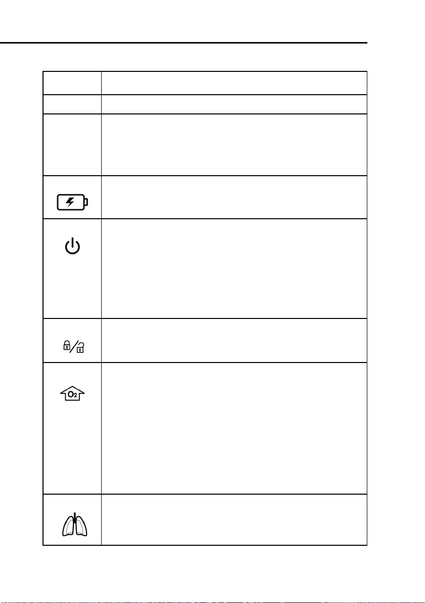
3 Battery charge indicator. Lights to show that the batteries can
be charged. It is lit whenever the ventilator is connected to AC
power or to > 20 V DC, whether or not power is switched on.
4 Power/standby switch. Powers the ventilator on and off
and accesses standby.
To put the ventilator into standby, press and quickly release the
switch, then select
Activate Standby
(For details on
standby, see Section 9.1).
To switch off ventilator power, press the switch quickly to access
standby, then press the switch again for > 3 s; or, if there is a
technical fault, press and hold the switch for > 10 s.
5 Screen lock/unlock key. Prevents inadvertent touchscreen
entries.
6O
enrichment key.
2
Infant/Neonatal option: Delivers 125% of the last oxygen setting
for 2 min. The backlit color changes to green and the currently
applied oxygen concentration is displayed on the oxygen knob
(green). Pushing the key a second time or manually changing the
oxygen concentration (FiO2) ends the oxygen enrichment period.
Adults and Pediatric: Delivers 100% oxygen for 2 min. The backlighting changes color to green and the actually applied oxygen
concentration is displayed on the oxygen control (green). Pushing
the key a second time or manually changing the oxygen concentration (FiO2) ends the 100% oxygen enrichment period.
7 Manual breath/inspiratory hold key. Triggers a mandatory
breath when pressed and released during exhalation. Triggers an
inspiratory hold when held down during any breath phase. For
details see Section 9.3.
1-14 624131/06
Page 43

Item Description
8 Nebulizer on/off key. Activates pneumatic nebulizer, during the
inspiration phase if high-pressure oxygen is connected. The indicator is lit whenever nebulization is active. Nebulization stops
automatically after 30 min. You can switch it off earlier by pressing the key again. For details, see Section 9.4.
9 Print screen key. Saves a JPG file of the used ventilator screen to
a USB memory key.
10 Alarm silence key. Silences the main ventilator audible alarm for
2 min. Pushing a second time cancels the alarm silence. The red
LED beside the key flashes when an alarm is active but not
muted. It is continuously lit while the alarm silence is active.
11 Press-and-turn (P&T) knob. Selects and adjusts ventilator set-
tings and selects monitored data. A green ring around the knob is
lit when power is switched on.
12 Expiratory valve cover and membrane
13 From patient port. The expiratory limb of the patient breathing
circuit and the expiratory valve are connected here.
14 To patient port. The inspiratory filter and the inspiratory limb of
the patient breathing circuit are connected here.
15 Flow sensor connection. Always attach the blue tube to the
blue connector and the clear tube to the silver connector.
16 Pneumatic nebulizer output connector
17 Oxygen cell with cover
624131/06 1-15
Page 44

1 General information
Figure 1-5. Rear view
Item Description
1 Serial number label
2 RS-232 connector
3 Fresh air intake and cooling fan vents
4 AC power cord with retaining clip
5 DC power connector
6 AC power receptacle
1-16 624131/06
Page 45

Item Description
7 Low-flow oxygen connector
8 High-pressure oxygen DISS or NIST inlet fitting
9 Option slot
Figure 1-6. Left side view
624131/06 1-17
Page 46

1 General information
Item Description
1 Graphical user interface tilt assembly
2 Expiratory valve cover exhaust port
Figure 1-7. Right side view
1-18 624131/06
Page 47

Item Description
1USB connector. For software update, event log, and configura-
tion setting export and import.
NOTE:
The USB connector is intended for passive
memory devices only.
2 Battery door
624131/06 1-19
Page 48

1 General information
1.3.3 Screen
Directly access all the windows for mode, controls, alarms, and
monitoring from the screen during normal ventilation. The
default screen is shown (Figure 1-8).
Figure 1-8. Default (basic) screen
Item Description
1 Active mode and patient group.
2 Main controls. The most important controls. Open the
trols
controls.
3 Window buttons (tabs). Open the associated windows.
window via the
Controls
button to show all ventilator
Con-
1-20 624131/06
Page 49

Item Description
4 Input power. Shows all available power sources. The framed
symbol indicates the current source (AC = mains, DC = DC
power supply, 1 = battery 1, 2 = battery 2 (optional). The green
part of each battery symbol shows the level of battery charge,
while the red shows the level of discharge.
5 Alarm silence countdown. Shows if alarm silence has been
activated. Displays the remaining silence time.
6 Graphic display. Shows the pressure/time waveform (curve)
plus one additional user-selected graphic, including another
real-time waveform or an Intelligent Panel.
7 Trigger symbol. Indicates the patient is triggering a breath.
8 Main monitoring parameters (MMP). You can view other
numeric parameters from the monitored parameter windows. If
the patient’s condition becomes critical, the colour of the
numeric parameters change to red and a high priority alarm
appears and to yellow for a medium priority alarm.
9Message bar. Displays alarm messages. If an alarm is active,
view the alarm buffer by touching the message bar. See Section
8 for further information.
10 Maximum Pressure Indication Line
11 Pressure limitation. Maximum Pressure - 10 cmH
O.
2
12 Inactive alarm indicator. Indicates that there is information
about inactive alarms in the alarm buffer. View the alarm buffer
by touching the inactive alarm indicator.
624131/06 1-21
Page 50

1 General information
1.4 Symbols used on device labels and packaging
Table 1-2. Symbols used on device labels and packaging
Symbol Definition
Power on/off switch
Manufacturer
Date of manufacture
Type B applied part (classification of medical electrical equipment, type B, as specified by IEC 60601-1)
Type BF applied part (classification of medical electrical equipment, type BF, as specified by IEC
60601-1)
Consult operator’s manual. Refer to the operator’s
manual for complete information. This label on the
device points the user to the operator’s manual for
complete information. In the operator’s manual,
this symbol cross-references the label.
1-22 624131/06
Page 51

Table 1-2. Symbols used on device labels and packaging (continued)
Symbol Definition
CE Marking of Conformity, seal of approval guaranteeing that the device is in conformance with the
Council Directive 93/42/EEC concerning medical
devices
Indicates the degree of protection against electric
shock according to IEC 60601-1. Class II devices
have double or reinforced insulation, as they have
no provision for protective grounding.
"The TÜV NRTL mark with the indicators “C“ and
“US“ means that the product complies with Canadian requirements and the requirements of US
authorities for safety."
Dispose according to Council Directive 2002/96/EC
or WEEE (Waste Electrical and Electronic Equipment)
Serial number
This way up at transport and storage
Fragile, handle with care at transport and storage
624131/06 1-23
Page 52

1 General information
Table 1-2. Symbols used on device labels and packaging (continued)
Symbol Definition
Keep dry at transport and storage
Temperature limitations at transport and storage
Humidity limitations at transport and storage
Atmospheric pressure limitations at transport and
storage
Stacking limitations at transport and storage
Recyclable materials
Read the operator’s manual
1-24 624131/06
Page 53

2
Preparing for ventilation
2.1 Introduction 2-2
2.2 Installing the patient tubing support arm 2-4
2.3 Installing the humidifier 2-5
2.4 Installing the option board 2-5
2.5 Installing the patient breathing circuit 2-6
2.6 Installing the pneumatic nebulizer 2-17
2.7 Setting up for monitoring by the optional CO2
sensor 2-19
2.7.1 CO2 mainstream measurement 2-20
2.7.2 CO2 sidestream measurement 2-24
2.8 Installing the optional Aeroneb Pro nebulizer 2-26
2.9 Using an expiratory filter 2-26
2.10 Connecting to primary power source 2-27
2.10.1Connecting to AC power 2-28
2.10.2Connecting to DC power 2-28
2.11 About the batteries 2-30
2.12 Connecting the oxygen supply 2-32
2.13 Connecting to an external patient monitor
or other device 2-33
2.14 Starting up the ventilator 2-34
2.15 Shutting down the ventilator 2-35
2.16 Display navigation guidelines 2-35
624131/06 2-1
Page 54

2 Preparing for ventilation
2.1 Introduction
WARNING
• Additional equipment connected to medical
electrical equipment must comply with the
respective IEC or ISO standards. Furthermore, all
configurations shall comply with the requirements for medical electrical systems (see IEC
60601-1-1 or clause 16 of edition 3 of IEC 606011, respectively). Anybody connecting additional
equipment to medical electrical equipment configures a medical system and is therefore
responsible that the system complies with the
requirements for medical electrical systems.
Also be aware that local laws take priority over
the above mentioned requirements. If in doubt,
consult your local representative or Technical
Support.
• To prevent possible patient injury, do not block
the holes at the back of the ventilator. These
holes are vents for the fresh air intake and the
cooling fan.
• To prevent back pressure and possible patient
injury, do not attach a spirometer, tube, or
other device to the exhaust port of the exhalation valve housing.
• To prevent interrupted operation of the ventilator or any accessories, use only accessories or
cables that are expressly stated in this manual.
• To prevent interrupted operation of the ventilator due to electromagnetic interference, avoid
using it adjacent to or stacking other devices on
it. If adjacent or stacked use is necessary, verify
the ventilator’s normal operation in the configuration in which it will be used.
2-2 624131/06
Page 55

• To prevent possible per-
sonal injury and equipment damage, make
sure the ventilator is
secured to the trolley or
shelf with the quicklocking mechanism.
• To prevent possible
equipment damage,
avoid tipping over the
ventilator when crossing
thresholds.
• To prevent possible
equipment damage, lock
the trolley’s wheels
when parking the ventilator.
CAUTION
• Before using the ventilator for the first time,
HAMILTON MEDICAL recommends that you
clean its exterior and sterilize its components as
described in Section 10.
• To electrically isolate the ventilator circuits from
all poles of the supply mains simultaneously,
disconnect the mains plug.
624131/06 2-3
Page 56

2 Preparing for ventilation
2.2 Installing the patient tubing support arm
WARNING
To prevent possible patient injury due to accidental
extubation, check the support arm joints and
secure as necessary.
Install the patient tubing support arm on either side of the
HAMILTON-C2 trolley. The arm snaps into place.
Figure 2-1. Installing the patient tubing support arm and
humidifier
1 Support arm mount
2 Humidifier slide bracket
2-4 624131/06
Page 57

2.3 Installing the humidifier
WARNING
• To prevent possible patient injury and possible
water damage to the ventilator, make sure the
humidifier is set to appropriate temperature
and humidification settings.
• To prevent possible patient injury and equip-
ment damage, do not turn the humidifier on
until the gas flow has started and is regulated.
Starting the heater or leaving it on without gas
flow for prolonged periods may result in heat
build-up, causing a bolus of hot air to be delivered to the patient. Circuit tubing may melt
under these conditions. Turn the heater power
switch off before stopping gas flow.
Install a humidifier to the HAMILTON-C2 using the slide bracket
on the trolley column. Prepare the humidifier as described in
the manufacturer’s operation manual.
2.4 Installing the option board
Install the option board as follows:
1. Remove the cover of the option slot.
2. Insert the option board containing the interfaces and fix it
with the screws.
624131/06 2-5
Page 58

2 Preparing for ventilation
Figure 2-2. Option board
2.5 Installing the patient breathing circuit
WARNING
• To minimize the risk of bacterial contamination
or physical damage, handle bacteria filters with
care.
• To prevent patient or ventilator contamination,
always use a bacteria filter between the ventilator and the inspiratory limb of the patient
breathing circuit.
• To reduce the risk of fire, use only breathing circuits intended for use in oxygen-enriched environments. Do not use antistatic or electrically
conductive tubing.
2-6 624131/06
Page 59

NOTE:
• For optimal ventilator operation, use HAMILTON
MEDICAL breathing circuits or other circuits that
meet the specifications given in Appendix A. When
altering the HAMILTON MEDICAL breathing circuit
configurations (for example, when adding accessories or components), make sure not to exceed these
inspiratory and expiratory resistance values of the
ventilator breathing system, as required by
IEC 60601-2-12: neonates, 6 cmH
O at 30 l/min.
2
• Any bacteria filter, HME, or additional accessories in
the expiratory limb may substantially increase flow
resistance and impair ventilation.
• To ensure that all breathing circuit connections are
leak-tight, perform the tightness test every time you
install a circuit or change a circuit part.
• Regularly check the water traps and the breathing
circuit hoses for water accumulation. Empty as
required.
• Do not combine the neonatal CO2 airway adapter
and the Adult Flow sensor. Artefacts during the measurement are possible.
624131/06 2-7
Page 60

2 Preparing for ventilation
1. Install the breathing circuit as follows:
1. Select the correct breathing circuit parts for your patient
from Table 2-1 and Table 2-2.
Table 2-1. Breathing circuit parts according to patient
height or IBW
Patient
height
(cm)
30 to
150 (11
to 59 in.)
> 130
(51 in.)
-- 0.2 to 3 ≤ 5 10 infant/
-- 3 to 30 3 to 7 15
IBW
(kg)
3 to 48 3 to 7 15 Pediatric/
> 30 ≥ 5 22
Trach
tube ID
(mm)
Breathing
circuit tube
ID (mm)
Flow
Sensor
adult
neonatal
Table 2-2. Tracheal tubes and CO2
Trach tube ID (mm) CO2 airway adapter
< 4 Neonatal/pediatric (sidestream)
≥ 4 Pediatric/adult (mainstream)
2. Assemble the patient breathing circuit. Figure 2-3 through
Figure 2-7 show six typical circuit configurations; for ordering information, contact your HAMILTON MEDICAL representative. Follow the specific guidelines for the different
parts.
3. Properly position the breathing circuit after assembly. Make
sure the hoses will not be pushed, pulled, or kinked during
patient’s movement, nebulization, or other procedures.
2-8 624131/06
Page 61

Figure 2-3. Patient breathing circuit for use with inspira-
tory heater wire (Pediatric/Adult) - (In place of the flex tube
shown, a 15 x 22 adapter may be used to attach the Flow Sen-
sor to the ET tube.)
624131/06 2-9
Page 62

2 Preparing for ventilation
Figure 2-4. Patient breathing circuit for use without
heater wires (Pediatric/Adult) - (In place of the flex tube
shown, a 15 x 22 adapter may be used to attach the Flow Sen-
sor to the ET tube.)
2-10 624131/06
Page 63

Figure 2-5. Patient breathing circuit for use with HME
(Pediatric/Adult) -
(In place of the flex tube shown, a 15 x 22 adapter may be
used to attach the Flow Sensor to the HME or ET tube.)
624131/06 2-11
Page 64

2 Preparing for ventilation
Figure 2-6. Patient breathing circuit with inspiratory
heater wire for use with nCPAP-PS (non-invasive ventila-
tion neonatal) - (Use a 15M x 15F adapter to connect the
infant flow sensor.)
2-12 624131/06
Page 65

Figure 2-7. Patient breathing circuit with inspiratory
heater wire (invasive ventilation neonatal) - (Use a 15M x
15F adapter to connect the infant flow sensor.)
624131/06 2-13
Page 66

2 Preparing for ventilation
Figure 2-8. LiteCircuit (single-limb) patient breathing cir-
cuit (non-invasive ventilation Pediatric/Adult) - (For use
with NIV or NIV-ST)
Expiratory valve membrane: Holding the expiratory valve housing (Figure 2-9) upside-down, seat the silicone membrane onto
the housing. The metal plate goes toward the ventilator. Position the housing and twist clockwise until it locks into place.
2-14 624131/06
Page 67

Figure 2-9. Installing the expiratory valve
1 Expiratory valve housing
2 Expiratory valve membrane
3 Metal plate toward ventilator
Flow sensor: Insert a Flow Sensor between the Y-piece of the
breathing circuit and the patient connection (Figure 2-10).
Connect the blue and colorless tubes to the Flow Sensor connectors in the front panel. The blue tube goes to the blue connector. The colorless tube goes to the silver connector.
624131/06 2-15
Page 68

2 Preparing for ventilation
NOTE:
To prevent inaccurate Flow Sensor readings, make sure
the Flow Sensor is correctly installed:
• The Flow Sensor tubings must not be kinked.
• The Flow Sensor tubings must be secured with clamp
(included with Flow Sensor).
• In the nCPAP-PS mode the correct position of the
flow sensor is at the expiratory valve.
Figure 2-10. Installing the Flow Sensor
2-16 624131/06
Page 69

2.6 Installing the pneumatic nebulizer
WARNING
• Do not use an expiratory filter or HME in the
patient’s breathing circuit during nebulization.
Nebulization can cause an expiratory side filter
to clog, substantially increasing flow resistance
and impairing ventilation.
• Connect the nebulizer in the inspiratory limb
per your institution’s policy and procedures.
Connecting the nebulizer between the Flow
Sensor and the endotracheal tube increases
dead space ventilation.
• To prevent the expiratory valve from sticking
due to nebulized medications, use only medications approved for nebulization and regularly
check and clean or replace the expiratory valve
membrane.
• Be aware that nebulization affects delivered
oxygen concentration.
NOTE:
• To change the nebulizer settings open the configuration mode.
• Nebulization is disabled during the neonatal application.
The nebulization feature provides a stable driving pressure to
power a pneumatic nebulizer connected to the nebulizer outlet, optimally specified for 6 to 7 l/min flow.
Connect the nebulizer and accessories as shown in Figure 2-11.
Table 1-1 has information about compatible nebulizers.
624131/06 2-17
Page 70

2 Preparing for ventilation
Figure 2-11. Installing a pneumatic nebulizer
1 Inspiratory limb
2 Nebulizer
3 Connector
4 Tube
2-18 624131/06
Page 71

2.7 Setting up for monitoring by the optional CO2
sensor
WARNING
• Always ensure the integrity of the patient
breathing circuit after insertion of the airway
adapter by verifying a proper CO
(capnogram) on the ventilator display.
• If the capnogram appears abnormal, inspect the
CO
airway adapter and replace if needed.
2
• Monitor the capnogram for higher-thanexpected CO2 levels during ventilation. These
can be caused by sensor or patient problems.
• Use the correct adapter. In adult patients small
geometrics may induce low tidal volumes and
intrinsic PEEP. In neonatal patients large geometrics detain effective CO2 removal.
• Do not use the CO2 sensor if it appears to have
been damaged or if it fails to operate properly.
Refer servicing to HAMILTON MEDICAL authorized personnel.
• To reduce the risk of explosion, do not place the
CO2 sensor in a combustible or explosive environment (for example, around flammable anesthetics or other ignition sources).
• Do not operate the CO
sensor when it is wet or
2
has exterior condensation.
• Avoid permanent direct contact of the CO2 sensor with the body.
• Nebulization may influence the CO2 measurements.
waveform
2
624131/06 2-19
Page 72

2 Preparing for ventilation
CAUTION
• Position airway adapters with windows in a
vertical, not a horizontal, position. This helps
keep patient secretions from pooling on the
windows.
• To prevent premature failure of the CO
HAMILTON MEDICAL recommends that you
remove it from the circuit whenever an aerosolized medication is delivered. This is due to
the increased viscosity of the medication, which
may contaminate the airway adapter window.
• All devices are not protected against reanimation with a defibrillator.
• Disconnect the CO2 sensor before using a defibrillator to the patient.
CO2 monitoring is used for various applications in order to gain
information such as the assessment of the patient’s airway
integrity or the proper endotracheal tube placement. For the
HAMILTON-C2 two possibilities to monitor CO2 are possible:
• mainstream CO2 measurement
• sidestream CO2 measurement
Whether, mainstream or sidestream CO2 is used to monitor
end-tidal CO2 depends on the clinical setting. A volumetric
capnogram as described in chapter “Volumetric Capnography”
is only possible with a mainstream CO2 sensor.
sensor,
2
2.7.1 CO2 mainstream measurement
WARNING
In NIV and neonatal ventilation with uncuffed
tubes leaks may influence the volumetric capnogram and the deduced numerical monitoring
parameters.
2-20 624131/06
Page 73

2.7.1.1 Introduction
The optional mainstream CO2 sensor is a solid-state infrared
sensor, which is attached to an airway adapter that connects to
an endotracheal (ET) tube or other airway and measures bases
flowing through these breathing circuit components.
The sensor generates infrared light and beams it through the
airway adapter or sample cell to a detector on the opposite
side. CO
airway adapter or aspirated into the sample cell, absorbs some
of this infrared energy. The HAMILTON-C2 determines the CO
concentration in the breathing gases by measuring the amount
of light absorbed by gases flowing through the airway or sample cell.
The HAMILTON-C2 can display measurements derived from the
sensor as numeric values, waveforms, trends, and loops.
CO
2
The waveform is a valuable clinical tool that can be used to
assess patient airway integrity and proper endotracheal (ET)
tube placement.
The CO
C2 ventilator to another, even "on the fly", during ventilation.
from the patient, flowing through the mainstream
2
sensor can be easily transferred from one HAMILTON-
2
2
2.7.1.2 Connecting the CO2 mainstream sensor
Set up the HAMILTON-C2 for CO2 monitoring, as follows:
1. Plug the sensor cable into the CO2 module connector (Figure 2-12), observing the orientation of the indexing guides
on the connector body. The cable should snap into place.
2. Attach the airway adapter to the CO2 sensor:
A. Verify that the adapter windows are clean and dry.
Clean or replace the adapter if necessary.
B. Align the arrow on the bottom of the adapter with the
arrow on the bottom of the sensor.
Press the sensor and the adapter together until they click
(Figure 2-12).
624131/06 2-21
Page 74

2 Preparing for ventilation
Figure 2-12. Connecting the CO2 sensor
Figure 2-13. Attaching the CO2 sensor to the airway adapter
1 CO2 sensor
2 Adapter
3. Connect the sensor/airway adapter to the patient circuit as
follows (Figure 2-14):
A. Place the sensor/airway adapter assembly at the proxi-
mal end of the airway circuit as shown. Do not place the
airway adapter between the ET tube and the elbow, as
2-22 624131/06
Page 75

this may allow patient secretions to accumulate in the
adapter.
B. Position the airway adapter with its windows in a verti-
cal, not a horizontal, position. This helps keep patient
secretions from pooling on the windows. If pooling does
occur, the airway adapter may be removed from the circuit, rinsed with water and reinserted into the circuit. To
prevent moisture from draining into the airway adapter,
do not place the airway adapter in a gravity-dependent
position.
Figure 2-14. Connecting the CO2 sensor/airway adapter
to the patient circuit
4. Check that connections have been made correctly by verify-
ing the presence of a proper CO
waveform (capnogram)
2
on the HAMILTON-C2 display. Monitor the capnogram for
higher-than-expected CO2 levels. If CO2 levels are higher
than expected, verify patient condition first. If you determine that the patient’s condition is not contributing, calibrate the sensor.
5. The sensor cable should face away from the patient. To
secure the sensor cable safely out of the way, attach sensor
cable holding clips to the airway tubing, then connect the
sensor cable to the clips.
624131/06 2-23
Page 76

2 Preparing for ventilation
To remove the sensor cable, pull back on the connector sheath
and disengage from connector.
2.7.2 CO2 sidestream measurement
2.7.2.1 Introduction
The optional side stream CO2 sensor samples gases over sampling port placed into the breathing circuit proximal to the
patient. The gas passes through sampling tube to the sample
cell. The sampling tube is water permeable in order to minimize cross interference effects and collision broadening. The
sampling cell measures the gas components are using infrared
spectroscopy at a wavelength of 4260 nm. The measured values can be displayed by the HAMILTON-C2 as real-time waveform, loops, and trends and as numeric values.
2.7.2.2 Connecting the CO2 sidestream sensor
WARNING
• Do not use patients that cannot tolerate the
removal of 50 ml/min from their total minute
ventilation.
Set up the device for CO2 sidestream monitoring, as follows:
1. Plug the LoFlo
TM
CO2 Module cable into the CO2 option
board connector (yellow), observing the orientation of the
indexing guides on the connector body. The cable should
snap into place.
2. The sample cell of the sampling kit must be inserted into
TM
the sample cell receptacle of the LoFlo
CO2 Module as
shown in the figure below. A “click” will be heard when the
sample cell is properly inserted.
2-24 624131/06
Page 77

Figure 2-15. Inserting the sample cell into the receptacle
3. Inserting the sample cell into the receptacle automatically
starts the sampling pump. Removal of the sample cell turns
the sample pump off.
4. Install the airway adapter between Flow Sensor and ET
tube.
5. The sample line should face away from the patient. To
secure the sample line safely out of the way, attach sensor
cable holding clips to the airway tubing, then connect the
sample line to the clips.
Figure 2-16. Attaching the CO2 sensor to the airway adapter
1 CO2 sensor
2 Adapter
624131/06 2-25
Page 78

2 Preparing for ventilation
To remove the sampling kit sample cell from the sample cell
receptacle, press down on the locking tab and pull the sample
cell from the sample cell receptacle.
2.8 Installing the optional Aeroneb Pro nebulizer
The Aerogen Aeroneb Pro nebulizer system is available as an
option for the HAMILTON-C2. Attach it to the mounting
bracket. Consult the operating instructions supplied with the
nebulizer for further installation and operating information.
Figure 2-17. Installing the Aeroneb Pro nebulizer
2.9 Using an expiratory filter
CAUTION
The use of an expiratory filter may lead to a significant increase in expiratory circuit resistance.
Excessive expiratory circuit resistance may compromise ventilation and increased patient work of
breathing and/or AutoPEEP.
2-26 624131/06
Page 79

NOTE:
Monitored parameters for increased expiratory resistance are not specific to the breathing circuit and may
indicate increased patient airway resistance and/or
increased resistance of the artificial airway (if used).
Always check the patient and confirm adequate ventilation.
An expiratory filter is not required on the HAMILTON-C2, but
you may use one according to your institution’s protocol. An
expiratory filter is not required, because the expiratory valve
design prevents internal ventilator components from contact
with the patient’s exhaled gas.
If you do use an expiratory filter, place it on the patient side of
the expiratory valve cover. Remove any expiratory filter or HME
during nebulization. Monitor closely for increased expiratory
circuit resistance. An
Exhalation obstruction
alarm may
also indicate excessive expiratory circuit resistance. If the
Exhalation obstruction
alarm occurs repeatedly, remove
the expiratory filter immediately. If you otherwise suspect
increased expiratory circuit resistance, remove the expiratory
filter or install a new filter to eliminate it as a potential cause.
2.10 Connecting to primary power source
Either AC or DC can supply the primary power to the HAMILTON-C2.
624131/06 2-27
Page 80

2 Preparing for ventilation
2.10.1 Connecting to AC power
NOTE:
• To prevent unintentional disconnection of the power
cord, make sure it is well seated into the ventilator
socket and secured with the power cord retaining
clip.
• The HAMILTON-C2 does not require protective earth
grounding, because it is a class II device, as classified
according to IEC 60601-1.
Connect the HAMILTON-C2 to an outlet that supplies AC
power between 100 and 240 V, 50/60 Hz. Always check the
reliability of the AC outlet. The AC power symbol in the bottom right-hand corner of the screen is displayed with a frame
around it.
2.10.2 Connecting to DC power
CAUTION
Connect the HAMILTON-C2 to the 12 to 24 V DC onboard power circuit of an ambulance vehicle only!
If the HAMILTON-C2 is connected to a DC power source the
DC power symbol in the bottom right-hand corner of the
screen is displayed with a frame around it.
2-28 624131/06
Page 81

2.10.2.1 Car adapter
NOTE:
• Only the HAMILTON car adapter is allowed to be use
• Connect the HAMILTON car adapter to the DC jack
• The input power of the car adapter, from 11 to 32 V
• The HAMILTON car adapter is intended to be used
• The use of the device for secondary transport in air-
A car adapter is available in order to connect the HAMILTONC2 to DC. The car adapter transfers input voltage to 24 V, and
allows for charging the batteries.
with the HAMILTON-C2.
of the HAMILTON-C2.
ensures that the batteries 1+2 of HAMILTON-C2 are
charged.
during secondary transport.
crafts is not permitted.
Figure 2-18. Car adapter
624131/06 2-29
Page 82

2 Preparing for ventilation
2.11 About the batteries
NOTE:
• The use of one battery is mandatory. The battery is
used as internal backup battery.
• HAMILTON MEDICAL recommends that the ventila-
tor’s batteries be fully charged before you ventilate a
patient. If the batteries are not fully charged and AC
power fails, always pay close attention to the level of
battery charge.
Two backup batteries, one mandatory and the other optional,
protect the HAMILTON-C2 from low, or failure of, the primary
power source. When the primary power source (either AC
mains or a DC power supply) fails, the ventilator automatically
switches to operation on backup battery with no interruption
in ventilation. An alarm sounds to signal the switchover. Silence
the alarm to confirm notification of the power system change;
this resets the alarm. If the optional battery (battery 2) is available and adequately charged, the ventilator switches to this
battery first. When battery 2 is depleted or not installed, the
ventilator switches to the standard battery (battery 1). The batteries power the ventilator until the primary power source is
again adequate or until the battery is depleted. Two batteries
power the ventilator typically for 6.5 h.
As a further safeguard, the HAMILTON-C2 provides a low battery alarm. It also has a capacitor-driven backup buzzer that
sounds continuously for at least 2 min when battery power is
completely lost.
The ventilator charges the batteries whenever the ventilator is
connected to either AC or DC > 20 V, with or without the ventilator power switch on. The battery charge indicator lights
show that the batteries are being charged.
2-30 624131/06
Page 83

Figure 2-19. Power source symbols and battery charge
indicator
1 Battery charge indicator
2 Crossed-out battery 1 means standard battery not available
3 AC mains symbol (or DC)
4 Frame indicates current power source
The power source symbols in the bottom right-hand corner of
the screen show the available power sources. A frame around a
symbol indicates the current ventilator power source. Green
indicates the level of battery charge.
Check the battery charge level before putting the ventilator on
a patient and before unplugging the ventilator for transport or
other purposes. A green symbol indicates a fully charged battery. A red and green symbol indicates a partially charged battery. If battery symbol 1 is crossed out, the standard battery is
discharged or defective. If battery symbol 2 is not shown, the
624131/06 2-31
Page 84

2 Preparing for ventilation
optional battery is not installed. If a battery is not fully charged,
recharge it by connecting the ventilator to the primary power
source for a minimum of 4 h, until the battery charge level is
80 to 100%. Alternatively, the battery can also be charged
with the external charger.
Section 9.3.2 describes how to replace the batteries.
2.12 Connecting the oxygen supply
CAUTION
• Always check the status of the oxygen cylinders
or other supply before using the ventilator during transport.
• Make sure oxygen cylinders are equipped with
pressure-reducing valves.
• To minimize the risk of fire, do not use high-
pressure gas hoses that are worn or contaminated with combustible materials like grease or
oil.
NOTE:
• To prevent damage to the ventilator, connect only
clean, dry medical-grade oxygen.
• Before starting ventilation, make sure the appropri-
ate oxygen source, either high-pressure oxygen (
) or low-pressure oxygen (
mode
selected during configuration, see Appendix J.
Oxygen for the HAMILTON-C2 can come from a high- or lowpressure source.
2-32 624131/06
LPO mode
HPO
), was
Page 85

High-pressure oxygen (Flow: ≤ 120 l/min, Pressure: 2.8 to 6
bar/280 to 600 kPa/41 to 87 psi), provided by a central gas
supply or a gas cylinder, is supplied through DISS or NIST male
gas fittings. With the optional cylinder holder, you can mount
oxygen cylinders to the trolley. If you use gases from cylinders,
secure the cylinders to the trolley with the accompanying
straps.
Low-flow oxygen (Flow: ≤ 15 l/min, Pressure: ≤ 6 bar/600 kPa/
87 psi) is provided by a concentrator or liquid cylinder. For
information about connecting low-pressure oxygen, see
Appendix F.
Connect the oxygen hose to the HAMILTON-C2’s high-pressure
or low-flow oxygen inlet fitting, shown in Figure 2-20.
Figure 2-20. Oxygen inlet fittings
1 Oxygen low pressure fitting
2 Oxygen high-pressure inlet fitting
2.13 Connecting to an external patient monitor
or other device
NOTE:
All devices connected to the HAMILTON-C2 must be for
medical use and meet the requirements of standard
IEC 60601-1.
624131/06 2-33
Page 86

2 Preparing for ventilation
You can connect your ventilator to a patient monitor, a Patient
Data Monitoring System (PDMS), or a computer via the RS-232
port. See Appendix I for details on the communications interface.
2.14 Starting up the ventilator
CAUTION
To ensure the ventilator’s safe operation, always
run the preoperational check before using the ventilator on a patient.If the ventilator fails any tests,
remove it from clinical use immediately. Do not use
the ventilator until necessary repairs are completed and all tests have passed.
NOTE:
If the HAMILTON-C2 is new, be sure it has been properly
configured for default language, alarms, and others (see
Appendix J).
1. Switch on the ventilator power switch. The ventilator will
run a self-test.
Figure 2-21. Power switch
1 Power switch
2-34 624131/06
Page 87

2. After a short time, you will see the patient setup window.
Set up the ventilator as described in Section 4.2.
3. Run the preoperational check (Section 3.2).
2.15 Shutting down the ventilator
NOTE:
The ventilator remains connected to power when the
power switch is switched off. This permits the batteries
to charge. To completely disconnect the ventilator from
power, unplug it from the mains power outlet or disconnect it from the DC supply.
To shut the HAMILTON-C2 down, press and quickly release the
power switch to access standby, then press the switch again for
> 3 s; or, if there is a technical fault, press and hold the switch
for > 10 s.
2.16 Display navigation guidelines
Use the touchscreen and the press-and-turn knob to access the
HAMILTON-C2 ventilation parameters and monitored data.
You typically use a select - activate or select - activate - adjust activate procedure.
To open a window, touch the window tab
to select and activate it; or turn the knob to
select the window tab (it is framed in yellow)
and then press the knob to activate your
selection.
To close a window, touch the window tab
or the X in the upper left-hand corner to
select and activate it; or turn the knob to
select the X (it is framed in yellow) and then press the knob to
activate your selection.
624131/06 2-35
Page 88

2 Preparing for ventilation
To adjust a control, touch the control to
select and activate it; or turn the knob to
select the control (it is framed in yellow) and
then press the knob to activate your selection. The activated control turns red. Turn
the knob to increment or decrement the
value. Press the knob or touch the control to
confirm the adjustment and deactivate.
To scroll through a log using the scroll bar
or arrows, touch the scroll bar to select and
activate it; or turn the knob to select the scroll
bar (it is framed in yellow) and then press it to
activate your selection. Your selection becomes
red when activated. Now turn the knob to scroll through the
log. Touch the scroll bar or press the knob to deactivate.
2-36 624131/06
Page 89

3
Tests, calibrations and utilities
3.1 Introduction 3-2
3.2 Running the preoperational check 3-4
3.3 System functions 3-6
3.3.1 Info: Viewing device-specific information 3-6
3.3.2 Tests & calib: Running sensor
calibrations and the tightness test 3-7
3.3.3 Sensors on/off: Enabling/disabling O2 and
CO2 monitoring 3-15
3.3.4 Setting day and night 3-16
3.3.5 Setting date and time 3-17
3.4 Utilities 3-18
3.4.1 Configuration: Configuring the ventilator
18
3.4.2 Data transfer: Copying event log data to a
USB memory device 3-19
3.5 Alarm tests 3-21
3.5.1 High pressure 3-21
3.5.2 Low minute volume 3-22
3.5.3 Low oxygen alarm 3-22
3.5.4 Disconnection on patient side 3-22
3.5.5 Loss of external power 3-23
3.5.6 Exhalation obstructed 3-23
3.5.7 Apnea 3-23
624131/06 3-1
Page 90

3 Tests, calibrations and utilities
3.1 Introduction
The tests and calibrations described in this section help verify
the safety and reliability of the HAMILTON-C2. Perform the
HAMILTON-C2’s tests and calibrations as described in Table
3-1. If a test fails, troubleshoot the ventilator as indicated or
have the ventilator serviced. Make sure the tests pass before
you return the ventilator to clinical use.
Table 3-1. When to perform tests and calibrations
When to perform Test or calibration
Before placing a new patient on the
ventilator
CAUTION
To ensure the ventilator’s
safe operation, always run
the full preoperational
check before using the ventilator on a patient. If the
ventilator fails any tests,
remove it from clinical use
immediately. Do not use the
ventilator until necessary
repairs are completed and
all tests have passed.
After installing a new or decontaminated breathing circuit or component
(including a Flow Sensor)
After installing a new oxygen cell or
when a related alarm occurs
Preoperational check
Tightness test, Flow Sensor calibration
Oxygen cell calibration
3-2 624131/06
Page 91

Table 3-1. When to perform tests and calibrations (continued)
When to perform Test or calibration
Required after installing a new, previously unused CO
sensor or when a
2
CO2 sensor/adapter calibration (main-
stream/ sidestream)
related alarm occurs, recommended
after switching between different airway adapter types
NOTE:
All calibration data is saved in
the sensor head. Therefore,
when a previously used sensor
is reconnected, you need not
recalibrate the sensor unless
you have changed the adapter
type.
As desired Alarm tests
624131/06 3-3
Page 92

3 Tests, calibrations and utilities
3.2 Running the preoperational check
CAUTION
To prevent possible patient injury, disconnect the
patient from the ventilator before running this
test. Make sure another source of ventilatory support is available.
When to perform: Before placing a new patient on the venti-
lator.
Required materials: Use the setup below appropriate to your
patient type. To ensure that the ventilator also functions
according to specifications on your patient, we recommend
that your test circuit be equivalent to the circuit used for ventilation.
Adult
patients
Pediatric
patients
Neonatal
patients
• Breathing circuit, 22 mm ID with 22F connectors
• Flow Sensor, pediatric/adult
• Demonstration lung, 2 l, with adult ET tube
between Flow Sensor and lung (PN 281637 or
equivalent)
• Breathing circuit, 15 mm ID with 22F connectors
• Flow Sensor, pediatric/adult
• Demonstration lung, 0.5 l, with pediatric ET
tube between Flow Sensor and lung
(PN 151816 or equivalent)
• Breathing circuit, 10 mm ID with 10F connectors
• Flow Sensor, infant
• Lung model, neonatal, with neonatal ET tube
between Flow Sensor and lung model (An IngMar neonatal lung model is recommended)
3-4 624131/06
Page 93

Procedure:
Do or observe... Verify... Notes
1. Connect ventilator
to AC or DC power
Breathing circuit is
assembled correctly.
and oxygen supply.
Assemble the
patient breathing
circuit.
2. Switch on power. When ventilator is
switched on, buzzer
sounds and the red
alarm lamp flashes.
After the self-test is
passed the alarm lamp
flashes red again.
3. Make sure the venti-
lator is in standby,
and select
check
Preop
from the
-
Patientsetup
window.
4. Open
System
Tests & calib
->
These tests pass. For details on running
window
(Figure 3-2). Select
and run the
ness
Flow Sensor
Tight-
test, then the
calibration. Follow all
prompts.
See Figure 2-2 through
2-7.
The buzzer sounds only
briefly in the beginning.
these tests and calibrations, refer to Section
3.3.2.
These tests pass. See Section 3.3.2.4.
5. If necessary, run
O2
cell calibra-
. Close win-
tion
dow.
624131/06 3-5
Page 94

3 Tests, calibrations and utilities
Do or observe... Verify... Notes
6. Generate an alarm
(for example, by disconnecting mains
power).
7. Resolve the alarm
situation (for example, reconnect mains
power).
Corresponding alarm
message in message bar
(for example,
external power
Alarm is reset.
Loss of
).
During standby, patient
alarms are suppressed.
Corrective action: If the ventilator does not pass the preoperational check, have it serviced.
3.3 System functions
NOTE:
The audible alarm is silenced during the calibration functions and for 30 s thereafter.
You can run tests and calibrations, view device-specific information, and perform other ventilator system functions from
System
the
3.3.1 Info: Viewing device-specific information
Open the
information.
window.
System
->
Info
window to view device-specific
3-6 624131/06
Page 95

Figure 3-1. Info window
3.3.2 Tests & calib: Running sensor calibrations and
the tightness test
NOTE:
To enable or disable O2 and CO2 monitoring see chapter 3.3.3.
Open the
tests and calibrations.
624131/06 3-7
System
->
Tests&calib
window to access the
Page 96

3 Tests, calibrations and utilities
Figure 3-2. Tests & calib window
3.3.2.1 Tightness test
NOTE:
• Make sure another source of ventilatory support is
available during this test. The patient must be disconnected from the ventilator during it.
• To cancel the tightness test while it is in progress,
select
Tightness
again.
3-8 624131/06
Page 97

Description: This test checks for leakage in the patient breathing circuit and determines the circuit’s compliance compensation factor. The ventilator is pressurized to 50 cmH
O. The
2
circuit is considered tight if this pressure can be maintained. If
there is a leak, the pressure falls in proportion to the size of
leak.
Procedure:
1. Set the ventilator up as for normal ventilation, complete
with the breathing circuit.
2. Activate
Tightness test
from the
dow.
3.
Disconnect patient
is now displayed. Disconnect the
breathing circuit at the patient side of the Flow Sensor. Do
not block the open end of the Flow Sensor.
Tighten patient system
4.
is now displayed. Block the
opening (a finger covered with an alcohol pad may be
used).
Connect patient
5.
is now displayed. Reconnect the
patient.
6. VERIFY that there is a green check mark in the box beside
Tightness
.
Corrective action:
Troubleshoot any alarms as described in Section 8.
3.3.2.2 Tightness test with the LiteCircuit
NOTE:
• Make sure another source of ventilatory support is
available during this test. The patient must be disconnected from the ventilator during it.
• To cancel the tightness test while it is in progress,
select
Tightness
again.
Tests&calib
win-
624131/06 3-9
Page 98

3 Tests, calibrations and utilities
Description: This test checks for leakage in the patient breathing circuit and determines the circuit’s compliance compensation factor. The ventilator is pressurized to 50 cmH
circuit is considered tight if this pressure can be maintained. If
there is a leak, the pressure falls in proportion to the size of
leak.
Procedure:
1. Set the ventilator up as for normal ventilation, complete
with the LiteCircuit.
2. Disconnect the Whisper valve together with Flow Sensor
from the circuit.
O. The
2
3. Activate
Tightness test
from the
Tests&calib
win-
dow.
4. The message line displays
Patient system
. Block the
opening with a clean gauze-covered finger.
5.
Connect patient
is now displayed. Reconnect the Whis-
per valve with Flow Sensor.
6. Repeat the
Tightness test
as described above (steps 3
to 4).
7. VERIFY that there is a green check mark in the box besides
Tightness
.
8. Reconnect the patient.
3-10 624131/06
Page 99

3.3.2.3 Flow Sensor calibration
NOTE:
• Make sure another source of ventilatory support is
available during this calibration. The patient must be
disconnected from the ventilator during it.
• To cancel the Flow Sensor calibration while it is in
progress, select
• Circuit resistance compensation measured during
calibration.
• If you are using a LiteCircuit, block the opening of
the whisper valve with a clean gauze-covered finger.
• Do not turn the infant Flow Sensor during calibration.
• The flow sensor must be on the correct position.
Intendíng to ventilate with nCPAP-PS, the flow sensor calibration has to be done with the flow sensor at
the proximal side of the patient and not at the expiration valve of the HAMILTON-C2.
FlowSensor
again.
Description: This calibration checks and resets the calibration
points specific to the Flow Sensor in use.
Procedure:
1. Set the ventilator up as for normal ventilation, complete
with breathing circuit and Flow Sensor.
2. Activate
Flow Sensor
from the
Tests&calib
window.
3. If you have not already disconnected the patient, the message line displays
Disconnect patient
. Disconnect the
patient now.
4. Follow the instructions displayed in the message line, turning the Flow Sensor as indicated.
5. VERIFY that the message line displays the green check
mark.
If the message line displays the red cross, rerun the test. If
the second attempt fails, install a new Flow Sensor.
624131/06 3-11
Page 100

3 Tests, calibrations and utilities
6. Reconnect the patient, as indicated.
Procedure for infant Flow Sensor:
1. Set the ventilator up as for normal ventilation, complete
with breathing circuit, Flow Sensor, and expiratory membrane and cover. Make sure that the
group is selected and that the infant Flow Sensor type is
installed.
Neonatal
patient
2. Activate
3.
If you have not already disconnected the
patient, the message line displays Disconnect
patient
4. VERIFY that the message line displays the green tick.
If the message line displays the red cross, rerun the test. If
the second attempt fails, install a new Flow Sensor.
5. Reconnect the patient, and close the
dow.
Corrective action: If the message bar displays
cal. needed
fails, install a new Flow Sensor.
Flow sensor
. Disconnect the patient now.
, run the calibration again. If the calibration still
from the
3.3.2.4 Oxygen cell calibration
NOTE:
• The oxygen cell calibration can be performed in the
standby mode only.
• The oxygen cell calibration requires that a HAMILTON
MEDICAL oxygen cell be installed and that the ventilator’s oxygen monitoring be enabled. To check for
an oxygen cell, see Section 10. To determine whether
oxygen monitoring is enabled, check the
Sensorson/off
• If using the low-pressure-mode disconnect all O2-
supplies during calibration. After reconnecting the
oxygen concentration is realised at 21 %.
window.
Tests&calib
Tests & calib
Flow Sensor
System
window.
win-
->
3-12 624131/06
 Loading...