

Page 1

Arc Module SU pH
Operating Instructions
Page 2

Hamilton Warranty
Please refer to the General Terms of Sales (GTS).
Important Note
Copyright © 2017 Hamilton Bonaduz AG, Bonaduz Switzerland. All rights reserved. The reproduction of any part
of this document in any form is forbidden without the express written agreement of Hamilton Bonaduz AG.
Contents of this manual can be modified without previous announcement. Technical modifications reserved.
Greatest possible care was used on the correctness of the information in this manual. If errors should be discovered
nevertheless, Hamilton Bonaduz AG is pleased to be informed about it. Regardless of this, Hamilton Bonaduz AG
cannot assume liability for any errors in this manual or for their consequences.
Page 3

TABLE OF CONTENTS
Table of Contents
1 General Information ............................................................................4
1.1 Intended Use ....................................................................................................... 4
1.2 About these Operating Instructions ..................................................................... 4
2 Liability .................................................................................................4
3 Safety Instructions .............................................................................. 5
3.1 General Precautions ............................................................................................ 5
3.2 Operation of the Arc Module ............................................................................... 5
3.3 Electrical Safety Precautions ............................................................................... 5
3.4 Chemical, Radioactive or Biological Hazard Precautions .................................... 6
4 Product Description ............................................................................ 6
4.1 General Description ............................................................................................. 6
4.2 Hardware Description ......................................................................................... 7
5 Installation ............................................................................................7
5.1 Unpacking and Cleaning ..................................................................................... 7
5.2 Electrical Connection ..........................................................................................8
5.3 Connection to PCS or Controller ......................................................................... 8
5.3.1 Layout and Overview ............................................................................... 8
5.3.2 Electrical connection of the 4–20 mA current interfaces .......................... 9
5.3.3 Electrical connection for the digital RS485 interface .............................. 12
5.4 Connection to PC or Mobile .............................................................................. 14
5.4.1 Layout and Overview ............................................................................. 14
5.4.2 ArcAir™ App ........................................................................................... 15
6 Operation ...........................................................................................16
6.1 Connecting the Arc Module to a OneFerm pH sensor ...................................... 16
6.2 Calibration ......................................................................................................... 16
6.3 Disconnecting the Arc Module from a OneFerm pH Sensor ............................. 17
7 Troubleshooting ................................................................................18
7.1 Arc Module and OneFerm pH Sensor Self-Diagnostics .................................... 18
7.1.1 Verify Status of Arc Module and OneFerm pH Sensor .......................... 18
7.1.2 Warnings ............................................................................................... 18
7.1. 3 E r r o r s ..................................................................................................... 19
7.2 Getting Technical Support ................................................................................ 19
7.3 Returning Arc Module for Repair ....................................................................... 19
8 Disposal ..............................................................................................20
9 Ordering Information ........................................................................20
9.1 Arc Module SU pH ............................................................................................ 20
9.2 OneFerm pH Sensors for the Arc Module SU pH ............................................. 20
9.3 Parts and Accessories ...................................................................................... 21
9.4 Services ............................................................................................................ 22
Arc Module SU pH Operating Instructions
3
Page 4

1 General Information
1.1 Intended Use
The Arc Module SU pH is intended to be used with the dedicated OneFerm pH sensors for the measurement
of pH in Single Use (SU) applications (see Chapter 9.2). This Module provides both a 4-20 mA and a digital
Modbus signal, when connected to a OneFerm pH sensor. Additional equipement such as amplifier or transmitter are not required.
The Arc Module SU pH is not gamma or steam sterilizeable.
1.2 About these Operating Instructions
This manual refers to the Arc Module SU pH designated as «Arc Module» for the OneFerm pH sensors from
Hamilton Bonaduz AG.
ATTENTION! Essential information for avoiding personal injury or damage to equipment.
NOTE: Important instructions or interesting information.
2 Liability
The liability of Hamilton Bonaduz AG is detailed in the document «General Terms and Conditions of Sale and
Delivery,» chapter 12.
Hamilton is expressly not liable for direct or indirect losses arising from use of the Arc Module or sensor. It must in
particular be insured in this conjunction that malfunctions can occur on account of the inherently limited useful life
of the Arc Module or sensor contingent upon their relevant applications. The user is responsible for the calibration
and maintenance of the Arc Module or sensor. In the case of critical applications, Hamilton recommends using
back-up measuring points in order to avoid consequential damages. The user is responsible for taking suitable
precautions in the event of a module failure.
GENERAL INFORMATION • LIABILITY
Page 5

3 Safety Instructions
ATTENTION! Read and follow the safety instructions carefully before installing and operating the
Arc Module.
3.1 General Precautions
For safe and correct use of the Arc Module, it is essential that both operating and service personnel follow
generally accepted safety procedures as well as the safety instructions given in this document, the «Arc Module
SU pH Operating Instructions».
Cleaning, assembly and maintenance should be performed by personnel trained in such work. When removing
and cleaning the Arc Module, it is recommended to wear safety goggles and protective gloves.
The Arc Module cannot be repaired by the operator and has to be sent back to Hamilton for inspection.
Necessary precautions should be taken when transporting the Arc Module. For repair or shipment the Arc
Module should be sent back in the original reusable packaging box. Every Arc Module sent back for repair
must be decontaminated (see also Chapter 7.3).
If the conditions described in these Operating Instructions are not adhered to or if there is any inappropriate
interference with the equipment, all of our manufacturer’s warranties become obsolete.
3.2 Operation of the Arc Module
The Arc Module must be used for its Intended Use (Chapter 1.1), and in optimum safety and operational
conditions. The specifications such as temperature or pressure defined on the Specification Sheet available
at www.hamiltoncompany.com must not be exceeded under any circumstances. Potential hazards exist if the
Arc Module is not operated correctly.
Strictily follow the instructions given to connect (Chapter 6.1) and disconnect (Chapter 6.3) the Arc Module
from a OneFerm pH sensor. Do not apply any forces to the bag or the OneFerm pH sensor. Faillure to do so
may break the OneFerm pH sensor and/or damage the bag integrity.
ATTENTION! Do not twist or turn the Arc Module to avoid damage or leakage.
3.3 Electrical Safety Precautions
Do not connect the Arc Module to a power source of any voltage beyond the power rating stated in the
Specification Sheet (www.hamiltoncompany.com).
Always use Hamilton VP cables for safe connection. Cables are available in a broad range of lengths
(Chapter 9.3). Make sure the cable is intact and properly plugged in to avoid any short circuit.
SAFETY INSTRUCTIONS
Arc Module SU pH Operating Instructions
5
Page 6

Keep the Arc Module away from other equipment which emits electromagnetic radio frequency fields, and
minimize static electricity in the immediate environment of Arc Module and sensor. Carefully follow all the
instructions in chapter 5 to avoid electrical damage to the sensor. The contacts must be clean and dry before
sensor is connected to the cable.
ATTENTION! Switch off the power supply and unplug the connector before dismounting the Arc
Module.
3.4 Chemical, Radioactive or Biological Hazard Precautions
Selection of the appropriate safety level and implementation of the required safety measures for working with
the Arc Module is the sole responsibility of the user.
If working with hazardous liquids, observe and carry out the maintenance procedures, paying particular
attention to cleaning and decontamination. If the Arc Module becomes contaminated with biohazardous,
radioactive or chemical material, it should be cleaned. Failure to observe and carry out the maintenance
procedures may impair the reliability and correct functioning of the measuring module.
4 Product Description
4.1 General Description
Optimal yields in bioprocesses are only obtained with extensive process control, especially precise monitoring
of pH value. The glass pH electrode is the most robust and reliable device available for the measurement of pH.
The reusable Arc Module converts the weak electrochemical signal of the OneFerm pH sensor into a digital
signal. The Arc Module stores all relevant sensor data, including calibration and diagnostic information, simplifying the calibration and maintenance. It directly connects to the PCS without a transmitter and provides either
4-20 mA or digital Modbus communication.
The Arc Module used with the OneFerm pH sensor is compatible with all other components of the Hamilton
Arc family, including a complete family of intelligent sensors (pH, ORP, dissolved oxygen and conductivity) and
accessories. Reusable and SU sensors can work on the same system. Additional wireless sensor diagnostics
functionality is enabled by the ArcAir™ App running on mobile devices (e.g. Hamilton’s Arc View Mobile) and
computers.
Key benefits include:
• Electrochemical pH measurement with stable measurement signal
• Reusable electronic, detachable from the sensor
• No separate transmitter needed
• Simple maintenance with robust industrial design
• Direct digital Modbus or analog communication to the PCS system via 4-20 mA standard signal
PRODUCT DESCRIPTION
Page 7

4.2 Hardware Description
Always check the Arc Module for possible defects after first unpacking. In the unlikely event of a damaged Arc
Module, return it immediately in original packing to your Hamilton representative.
ARC LOGO, SERIAL AND REF NUMBER SOCKET WITH VP6 CONNECTOR
COLOR CODING FOR ONEFERM pH SENSORS
SOCKET HEAD WITH VP8 CONNECTOR
COUPLING NUT
Figure 1: Arc Modu le SU pH
The Arc Module and OneFerm pH sensors are delivered directly from the factory, pre-calibrated according to
operational specifications. The integrated 4–20 mA analog interface and RS485 digital interface (Modbus RTU) are
configured according to factory defaults. Full details, including serial number and most important specifications
can be found on the sensor tag provided with each sensor.
To be sure to avoid electrical damage to the sensor, carefully follow all the instructions in the section entitled
«Electrical Connection.» Before using the sensor for measurement, monitoring or regulation, be sure to first check
its configuration by means of an operational test.
5 Installation
5.1 Unpacking and Cleaning
1. Carefully unpack the Arc Module SU pH. Enclosed you will find the Arc Module and the Arc Module SU pH
Quick Guide.
2. Inspect the sensor for shipping damages or missing parts.
3. For cleaning purposes of the Arc Module, soak a paper towel with Isopropanol 70% and wipe down the
module. After cleaning the module, air dry the isopropanol prior to connecting with the sensor. Make sure
that all contacts of module and sensor are completely dry to prevent electrical damage (short circuit).
NOTE: Arc Module is not designed for gamma or steam sterilization.
INSTALLATION
Arc Module SU pH Operating Instructions
7
Page 8
ATTENTION! The sensor can measure and communicate over digital RS485 interface up to a temperature of 60 °C. If the process temperature exceeds 50 °C, both 4-20 mA interfaces are set to 3.5 mA
output. The analog measurements will continue when the temperature drops back below 50 °C.
NOTE: The performance of the OneFerm pH sensor can change by damage of the electrodes in aggressive
media, high temperature, or by contamination of the electrodes during the sensor’s lifetime. A quality indicator
of the Arc Module shows deviation of the zero point when performing a product calibration. The quality indicator
status is updated automatically after each product calibration.
5.2 Electrical Connection
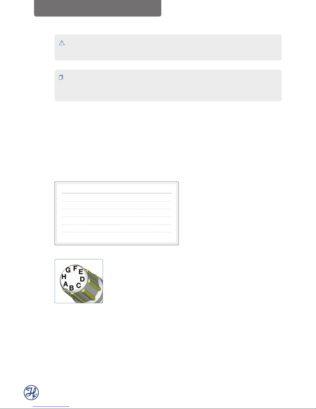
The Arc Module is fitted with a VP8 socket head. The eight golden contacts are denoted as pin A to pin H.
For easy identification of each pin, the head has a notch between pin A and pin B.
For the easiest and safest connection of Arc Module, always use Hamilton VP8 cables, available in a range of
different lengths. To ensure highest signal quality standard, a cable between the OneFerm pH sensor and the
Arc Module is not recommended.
VP Pin Function
A 4–20 mA interface (mA interface #2)
B 4–20 mA interface (mA interface #1)
C Power supply: +24 VDC (7 to 30 VDC)
D Power supply: Ground
G RS485 (A)
H RS485 (B)
Figure 2: Pin configuration
5.3 Connection to PCS or Controller
5.3.1 Layout and Overview
The Arc Module can be connected to the PCS or controller by a wired connection (for reference numbers
see also «Parts and Accessories»):
INSTALLATION
Page 9

INSTALLATION
SENSOR DATA CABLE VP8
COMMUNICATON TO PCS VIA:
• 4-20 mA
• MODBUS RTU
PCS OR
CONTROLLER
ARC MODULE SU pH
ARC WI ADAPTER BT
(optional)
ONEFERM pH VPxxx NTC
Figure 3: Layout wired connectio n to PCS or controller
The digital RS485 interface of the Arc Module can be accessed by operators when integrated by the OEM
system supplier. The three-tier operator levels and factory default passwords are shown in the table below.
Operator Status Operator Level Password Read Calibrate Configure
User U -
– –
Administrator A 18111978
–
Specialist S 16021966
5.3.2 Electrical connection of the 4–20 mA current interfaces
The 4–20 mA interface enables direct connection of the Arc Module to a data recorder, indicator, control unit
or PCS with analog I/O. Apart from the two wires used for 4–20 mA current loop no additional equipment is
required for analog signaling. The Arc Module is delivered from the factory with the analog 4–20 mA interface
set «active». When using the 4–20 mA interface, pins have the following designations with respect to VP cable
conductor colors:
VP Pin VP8 Cable Arc Module
A Yellow 4–20 mA three-wire interface, functions as a current sink. It
regulates the input current according to the sensor measurements.
This interface needs a separate power supply (pin B or C). Factory
default is assigned to a temperature measurement.
B Green 4–20 mA two-wire interface, functions as a current sink. It regulates
the input current according to the sensor measurements. This interface
can be powered directly from 4–20 mA two-wire current loop. Nominal
power of 60 mW must be provided. Factory default is assigned to a
pH measurement.
C Red Power supply: +24 VDC (7 to 30 VDC).
Max. power consumption: 150 mW
D Blue Power supply: Ground
Arc Module SU pH Operating Instructions
9
Page 10

The 4–20 mA interface is configured at the factory with the range, value and measurement units as indicated
on the certificate. Follow the instructions in the section entitled «Configuration and Monitoring of the Sensor» to
adjust the sensor according to the requirements of your application.
Controlling 4–20 mA current interface signals by pulse-width modulation
Hamilton Arc Module use the method of pulse-width modulation (PWM) to adjust the DC currents of the
4–20 mA interfaces corresponding to the measured values. In principle, the pulse width (ti) of a rectangular
signal with a constant frequency, the pulse duty factor (ti / T), is modulated and afterwards demodulated by
a low-pass filter to generate continuous analog DC signals. The resulting value yi corresponds to the average
of the PWM signal (see Figures 3 and 4). The PWM-loads of the Arc Module have low-pass filters which are
not able to eliminate all AC fractions of the used PWM frequency of 3.5 kHz due to technical impossibilities.
Therefore, the current signals of the 4–20 mA interfaces are still overlaid by a certain AC current which should
be masked by lag smearing or input filters of the current input card of the process control system (PCS).
Recommended PCS settings are a sampling rate below 3 kHz, an averaging over more than 1 s, and the use
of galvanically separated inputs to avoid oscillations. It is also possible to use mathematical functions or isolating amplifiers for signal processing filtering if necessary. For detailed technical advice about suitable isolating
amplifiers, please contact Hamilton technical support.
Figure 4: Prog ress of a rectangular signal with a period T and a pulse duration t1 for the generation of an analog signal with the value y1.
Figure 5: Prog ress of a rectangular signal with a period T and a pulse duration t2 for the gene ration of an analog signal with the value y2.
INSTALLATION
Page 11

INSTALLATION
ATTENTION! The Arc Module generates the 4 –20 mA signals by pulse width modulation (PWM) which
is not compatible to all PCS systems. Also a galvanic separation between the power supply and the PCS
is necessary for correct sensor functionality when used in 4 –20 mA setups (see Figure 5).
Analog interface 1 and 2
Galvanically not isolated, pulse width modulation with 3.5 kHz, recommended PCS settings:
• Use galvanically separated inputs
• Sampling rate < 3 kHz and ≠ n * 3.5 KHz
• Average over > 1 s
Examples of circuit arrangement
+
-
Arc Module
PCS
VP pin B
VP Pin C
VP pin D
+ 24 VDC
4–20 mA
regulation
4–20 mA cu rrent
u
Analog Input
0 VDC; GND
Figure 6: Two-wire loop wiring diagram for the 4–20 mA interface
(mA inter face #1). In this wiring scheme, power is not suppl ied
to the sensor VP pin C, therefore the wiring is not applicable to a
sensor with the Arc Wi Adapter BT.
+
-
Arc Module
PCS
VP pin B
Arc Module
power
VP Pin C
VP pin D
+ 24 VDC
4–20 mA
regulation
4–20 mA cu rrent
U (7–30 VDC) Pow er Suppl y Sensor
u
Analog Input
0 VDC; GND
Figure 7: Three-wire loop wiring di agram for the 4–20 mA
interfaces. The figure represents both 4–20 mA inte rfaces at
pin A and pin B.
+
-
Arc Module
PCS
VP pin B
Arc Module
power
VP Pin C
VP pin D
+ 24 VDC
0 VDC; GND
+
-
input
output
4–20 mA
regulation
+
-
4–20 mA cu rrent
U (7–30 VDC) Pow er Suppl y Sensor
u
Analog Input
0 VDC; GND
Figure 8: The safest form of wiring, us ing an isolation amplifier.
The figure represe nts both 4–20 mA interfaces at pin A and
pin B. For detailed te chnical advice, please contact Hamilton
technical support.
Arc Module SU pH Operating Instructions
11
Page 12

5.3.3 Electrical connection for the digital RS485 interface
The digital RS485 interface enables communication with Arc Module for the OneFerm pH sensor to perform
measurements, calibrate the sensor and change the sensor’s configuration parameters. Arc Modules are always
connected to digital controlling devices as a Modbus slave. To function, they require a power supply using VP8 pins C and D. See Figure 8 below. The section entitled «Configuration and Monitoring of the Sensor»
describes operation in digital mode.
By using the correct access password the system operator can adapt Arc Module to many tasks by:
• Selecting the 4–20 mA interface
• Scaling (configuring) the 4–20 mA interface
• Selecting the measured parameter:
- pH: mV, pH
- Temperature T: °C; K, °F
In addition, operators can read sensor information from the RS485 interface such as:
• The sensor’s serial number (SN), reference number (Ref) and manufacturing number (Lot)
• The Arc Module firmware version
• The Arc Module status (e.g., operation hours, warnings and errors)
Additional information:
The Modbus RTU communication protocol corresponds to the Modbus-IDA standard (see www.modbus.org).
Arc Module for OneFerm pH sensors use an open register set developed by Hamilton. Additional information
about the Modbus RTU communication protocol can be found in the «Arc Module SU pH Programmers
Manual» at www.hamiltoncompany.com.
ATTENTION! Because all Arc Modules are delivered with factory-default settings, each sensor must be
configured for its specific application before first use (See the section entitled «Configuration of the Arc
Module» for more information).
The pins for the digital RS485 interface have the following designation with respect to VP cable conductor
colors:
Arc pH VP Pin VP8 Cable
Power supply: +24 VDC (7 to 30 VDC)
Max. power consumption 150 mW C Red
Power supply: Ground D Blue
RS485 (A) G Grey
RS485 (B) H Pink
In an electromagnetically noisy environment, it is advisable to connect the VP cable shield to the ground.
This significantly improves resistance to noise and signal quality.
INSTALLATION
Page 13

INSTALLATION
Examples of circuit arrangement
Arc Module
PCS
VP pin G
VP Pin C
VP pin D
+ 24 VDC
RS485 A
VP pin H
RS485 B
Figure 9: Wiring diagram for the RS485 inter face.
Figure 10: Multi-drop bus wiring for the Modbus two-wire mode. Each sensor functions as a Modbus slave.
NOTE: In the connection scheme shown above, each sensor must have the unique Modbus device
address for proper communication.
The serial Modbus connection between the RS485 port of the master and the corresponding interfaces of the
sensors has to be ensured according to the EIA/TIA RS485 standard. Only one sensor can communicate with
the master at any time.
Arc Module SU pH Operating Instructions
13
Page 14

5.4 Connection to PC or Mobile
5.4.1 Layout and Overview
The Hamilton Arc View Mobile (Ref 243690) represents an ideal solution for Arc sensor management. This
includes an automated calibration by scanning the QR-code of the OneFerm pH sensor tag. The Arc View
Mobile included in the package is a compact mobile wireless device with long battery lifetime and broad
functionality. When using with a mobile device, each Arc Module requires an Arc Wi Adapter BT (Ref 243460
or 243470) and an Arc USB Power Cable (Ref 243490-01 or -02) for external power supply. The Arc View
Mobile is based on the Samsung Galaxy Tab Active tablet and comes pre-configured with ArcAir™ App, app
blocker application, power supply cable, instruction manual and Hamilton quick guide.
ArcAir ON PC OR MOBILE:
• ARC VIEW MOBILE PACKAGE
• ARC WIRELESS CONVERTER BT
ARC USB POWER CABLE
ARC WI ADAPTER BT ARC MODULE SU pH ONEFERM pH VPxxx NTC
Figure 11: Layout for wirele ss connection
A wired connection to the PC is possible using the USB port. For connection to the PC, an Arc USB Power
Cable (Ref 243490-01) is needed.
ArcAir on PC
ARC WI ADAPTER BT
(optional)
ARC USB POWER CABLE (on PC) ARC MODULE SU pH ONEFERM pH VPxxx NTC
Figure 12: Layout wired conne ction to PC or notebook
INSTALLATION
Page 15

INSTALLATION
5.4.2 ArcAir™ App
The ArcAir™ App can be used to display measurement values, for configuration and calibration or to
generate GMP reports for calibration, verification, communication and configuration. It can be downloaded
from App Store, Google Play or for PC on www.hamiltoncompany.com. To upgrade your PC version from
basic to advanced version, you must connect your PC using the Arc Wireless Converter BT with your mobile
device. For this purpose, the mobile device must run on the correct ArcAir version (Advanced) to activate
the upgrade on your PC (for more details, see also «ArcAir™ App – Operating Instructions» on
www.hamiltoncompany.com).
ArcAir Lite (read only) user can read sensor information such as:
• Arc Module and sensor status (e.g. warnings and errors or quality indicator)
• Measurement values
• Arc Module and sensor information serial number (SN), reference number (Ref) and manufacturing
number (Lot)
• Arc Module and sensor settings
ArcAir Basic user can use ArcAir Lite functionality and in addition:
• Execute initial calibration including calibration report (see chapter 6.2)
• Product calibration (follow the wizard of the ArcAir™ App)
• Configure the Arc Module and sensor setting including configuration report
ArcAir Advanced user can use ArcAir Basic functionality and in addition can create:
• GMP-reports for verification and communication settings
• Configuration profile
ArcAir Version Read Calibrate Configure GMP-Package
Lite
– – –
Basic
–
Advanced
Arc Module SU pH Operating Instructions
15
Page 16

6 Operation
NOTE: This operation description refers to ArcAir™ App. For operation with PCS refer to operating instructions
from the OEM system supplier.
ATTENTION! Only use the Arc Module according to the «Specification Sheet» on
www.hamiltoncompany.com. Failure to do so may lead to damages or measurement failure.
6.1 Connecting the Arc Module to a OneFerm pH sensor
ATTENTION! Do not screw in the OneFerm pH sensor while connecting the Arc Module to avoide
any leakage.
Prepare the sensor for measurement as follows:
1. Carefully remove the protective caps from the VP head.
2. Connect the Arc Module to the OneFerm pH sensor (Hold the Arc Module housing and screw in the
coupling nut)
3. Make sure that the Arc Module is configured as required. If in doubt, test as described in chapter 5.3
«Connection to PCS or Controller»
4. Connect the Arc Module SU pH to the OneFerm pH sensor according to the section «Electrical
Connection» in the desired configuration (analog 4–20 mA interface, digital RS485 interface or both).
The signal stabilizes itself within a few minutes. The Arc Module is programmed with default calibration values.
To achieve best accuracy, execute calibration of the sensor (chapter 6.2).
6.2 Calibration
The OneFerm pH sensor has been pre-calibrated at pH 4 and pH 7 at 25 °C; hence calibration prior to the
process is not necessary. The calibration values for zero point and sensitivity (slope) can be found on the label
attached to the sensor head.
Figure 13: Example sensor label with calibr ation data.
OPERATION
Page 17

1. Read the zero point (mV) and sensitivity (mV/pH) written on the sensor label (see figure 13).
2. Enter the calibration and sensor data into the Arc Module:
Calibration data (mandatory):
- Zero-Point
- Sensitivity
Sensor data (enter data for traceability):
- Ref-number
- Name
- Lot-number
- Lot date
- SN-number
- Sensor ID
- a-length
Push the save button to save the data.
3. If required, perform a product calibration step to increase accuracy to ± 0.1 pH (valid within 2 pH units
from the product calibration point and at measurement temperature).
4. Save the data to the Arc Module
NOTE: The Arc View Mobile supports automatic calibration for predefined calibration values by scanning
the QR-code. Use ArcAir software on tablet or PC to perform manual input of the calibration data.
The concept behind Hamilton single use Arc System enables calibration based on the pre-calibrated values.
Additional 2-point calibration for the installation in the process setup is not required.
Product calibration
Product calibration is an in-process calibration procedure that adjusts the measurement to specific process
conditions. Follow the wizard of the ArcAir™ App.
In order to restore the original standard calibration curve, the product calibration can be cancelled at any time.
6.3 Disconnecting the Arc Module from a OneFerm pH Sensor
ATTENTION! Do not unscrew the OneFerm pH sensor while disconnecting the Arc Module to avoide
any leakage.
1. Hold the Arc Module housing
2. Unscrew the coupling nut
3. Remove the Arc Module from the OneFerm pH sensor
The OneFerm pH sensor is a single use sensor meant to be discarded with the bag. If the process requires
disconnection, the sensor must be decontaminated prior to disposal.
OPERATION
Arc Module SU pH Operating Instructions
17
Page 18

7 Troubleshooting
7.1 Arc Module and OneFerm pH Sensor Self-Diagnostics
7.1.1 Verify Status of Arc Module and OneFerm pH Sensor
The Arc Module and OneFerm pH sensor provides a self-diagnosis functionality to detect and identify the
most common sensor malfunctions. The communication interfaces can be used for warning and error massages. The analog 4-20 mA interface can be configured according to the NAMUR recommendations to
indicate an abnormal event. Use the ArcAir™ App for monitoring the sensor status and for troubleshooting.
The following types of messages are provided by the self-diagnosis function.
Indicator status What does it mean?
Status symbol on the ArcAir
™
App The connectivity to the sensor is OK. The sensor
respectively LED on Arc Wi Adapter BT is operating correctly and no warnings or errors
are green. have been registered.
Status symbol on the ArcAir
™
App The connection to the sensor is OK. However, the
respectively LED on Arc Wi Adapter BT sensor indicates a warning. Verify the sensor
are yellow. warnings in «Info > Status».
Status symbol on the ArcAir
™
App The connection to the sensor is OK. However, the
respectively LED on Arc Wi Adapter BT sensor indicates an error. Verify the sensor error
are red. in «Info > Status».
Status symbol on the ArcAir
™
App is The ArcAir™ App lost connection to the sensor
grey respectively LED on Arc Wi Adapter due to one of the following reasons:
BT for a sensor is flashing red. • The wireless signal strength is low (ArcAir
indicator grey; LED on Arc Wi Adapter BT can
be green/yellow/red)
• The Arc Wi Adapter BT has been removed from
the sensor.
• The Arc Module or Arc Wi Adapter BT
electronic is defective.
7.1.2 Warnings
Warnings Cause Solution
pH reading below lower limit pH-reading too low (pH < 3) Verify calibration data (Chapter 6.2)
pH reading above upper limit pH-reading too high (pH > 10) Verify calibration data (Chapter 6.2)
Verify / set calibration data Arc Module was disconnected Verify calibration data (Chapter 6.2)
from power supply or from the
OneFerm pH sensor
Calibration recommended No calibration executed Verify calibration data (Chapter 6.2)
TROUBLESHOOTING
Page 19

7.1.3 Errors
Errors (failures) Cause Solution
pH reading failure The OneFerm pH sensor is broken Replace the sensor
Glass resistance too high The OneFerm pH sensor is broken Replace the sensor
Glass resistance too low The reference system of the Replace the sensor
OneFerm pH sensor is broken
Temperature out of The measured temperature is outside If the process temperature is
measurement range the defined measurement temperature outside this range, the sensor
range (4-50 °C) will not perform pH reasings
Temperature out of The measured temperature is outside the The sensor can be damaged
operating range defined operating temperature range (0-60 °C)
Sensor missing No sensor connected to the Arc Module Connect OneFerm sensor
Sensor not matching Wrong sensor connected to the Arc Module Connect OneFerm pH
NTC sensor
Temperature sensor The temperature sensor in the OneFerm pH Replace the sensor
sensor is broken
Sensor quality low Quality indicator too low Verify calibration data or
repeat product calibration
(Chapter 6.2)
Internal communication Hardware defect of Arc Module Replace Arc Module
failure
7.2 Getting Technical Support
If a problem persists even after you have attempted to correct it, contact Hamilton`s Customer Support:
Please refer to the contact information at the back of this Manual.
7.3 Returning Arc Module for Repair
Before returning an Arc Module to Hamilton for repair, contact our Customer Service and request: a Returned
Goods Authorization (RGA) or Returned Material Authorization (RMA) number.
Do not return an Arc Module to Hamilton without an RGA/RMA number. This number assures proper
tracking of your sensor. Arc Modules that are returned without an RGA number will be sent back to the
customer without being repaired.
Decontaminate the Arc Module and remove health hazards, such as radiation, hazardous chemicals,
infectious agents, etc. Provide complete description of any hazardous materials that have been in contact
with the sensor.
TROUBLESHOOTING
Arc Module SU pH Operating Instructions
19
Page 20

8 Disposal
The design of Hamilton sensors optimally considers environmental compatibility. In accordance with
the EC guideline 2002/96/EG Hamilton sensors that are worn out or no longer required must be
sent to a dedicated collection point for electrical and electronic devices, alternatively, must be sent to
Hamilton for disposal. Sensors must not be sent to an unsorted waste disposal point.
9 Ordering Information
9.1 Arc Module SU pH
Ref Description
243233 Arc Module SU pH
9.2 OneFerm pH Sensors for the Arc Module SU pH
Ref Description Length
243235 OneFerm pH VP70 NTC 70
243236 OneFerm pH VP120 NTC 120
243237 OneFerm pH VP225 NTC 225
243238 OneFerm pH VP325 NTC 325
DISPOSAL • ORDERING INFORMATION
Page 21

ORDERING INFORMATION
9.3 Parts and Accessories
Arc Vi ew Mobile (Ref 243690) Arc USB Power Cab le (Ref 2 43490- 01 or -0 2)
Arc USB Power Cable available with VP8 connector for the Arc Wi 1G
Adapter BT or wi th M12 8-pole connector for the Arc Wi 2G Adapter BT
iOS Android
Arc Wi 1G Ad apter BT (Ref 24 346 0) Arc Wi 2G Adapter BT (Ref 24 3470) Arc Wireless Converter BT (Ref 24 349 9)
for Wireless Communication (recommended whe n integrated
(recommended for Modbus-Integrations) via 4–20 mA i nterface)
Arc Module SU pH Operating Instructions
21
Page 22

Ref Description
243460 Arc Wi 1G Adapter BT
243470 Arc Wi 2G Adapter BT
243490-01 Arc USB Power Cable VP8
243490-02 Arc USB Power Cable M12 8-pole
243499 Arc Wireless Converter BT
243690 Arc View Mobile Package
355263 Sensor Data Cable VP8, 1m
355264 Sensor Data Cable VP8, 3m
355265 Sensor Data Cable VP8, 5m
355266 Sensor Data Cable VP8, 10m
355267 Sensor Data Cable VP8, 15m
355268 Sensor Data Cable VP8, 20m
9.4 Services
OEM Training session
On-site training (2-day)
Description: Imparting of fundamental knowledge
about pH sensor measuring technology and PCS
integration incl. documents and participation
confirmation, excl. travel costs
ORDERING INFORMATION
Page 23

NOTES
Arc Module SU pH Operating Instructions
23
Page 24

© 2017 Hamilton Bonaduz AG. All rights reserved.
All trademarks are owned and/or registered by Hamilton Bonaduz AG.
627106 /00 — 08/2 017
Hamilton Americas & Pacific Rim
4970 Energy Way
Reno, Nevada 89502 USA
Tel: +1-775-858-3000
Fax: +1-775-856-7259
sales@hamiltoncompany.com
Hamilton Europe, Asia & Africa
Via Crusch 8
CH-7402 Bonaduz, Switzerland
Tel: +41-5 8- 610-10-10
Fax: +41-58- 610-00-10
contact.pa.ch@hamilton.ch
Web: www.hamiltoncompany.com
USA: 800-648-5950
Europe: +41-58-610-10-10
To find a representative in your area, please visit www.hamiltoncompany.com.
 Loading...