

Page 1

A
l
t
o
Sta
r
®
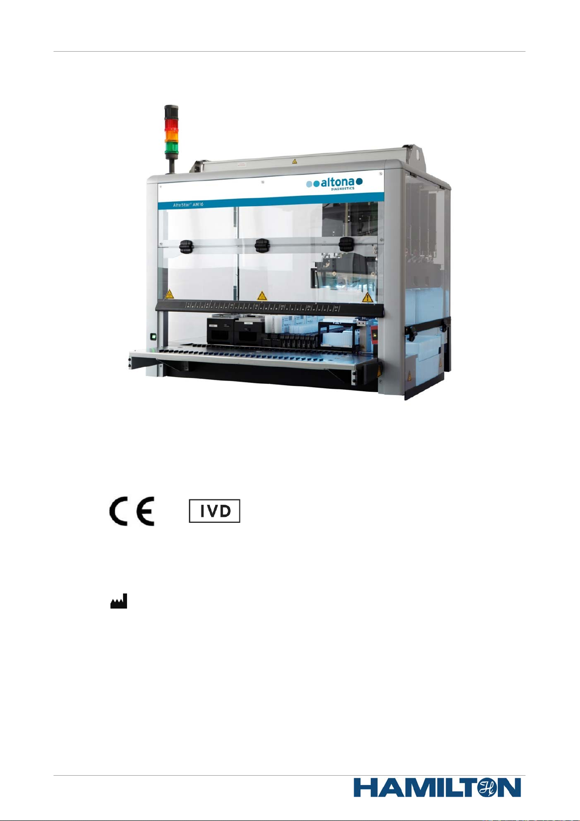
AltoStar®
Automation System AM16
Operator`s Manual IVD
10/2017 EN
Page 2
AltoStar® Automation System AM16 – OPERATOR’S MANUAL IVD
Important notice
This manual may not be used or reproduced in an y way whatsoever without the express written
consent of Hamilton Bonaduz AG.
HAMILTON Bonaduz AG • Via Crusch 8 • CH-7402 Bonad u z.
Copyright 2017 Hamilton Bonaduz AG, All Rights Reserved.
AltoStar is a registered trademark of altona Diagnostics GmbH.
Microlab is a registered trademark of Hamilton Bonaduz AG.
Microtiter is a registered trademark of Dynatech Laboratories.
627108_00
Deconex is a registered trademark of Borer Chemie AG Switzerland.
Windows 7 and Windows 10 are registered trademarks of Microsoft Corporation.
CFX96 Deep Well IVD Real-Time PCR Detection System is a trademark of Bio-Rad.
Page 3

AltoStar® Automation System AM16 – OPERATOR’S MANUAL IVD
Table of Contents
1 Safety and General Information .................................................................................... 1
1.1 About this Manual .......................................................................................................................... 1
1.2 Additional Manuals ........................................................................................................................ 2
1.3 Intended Use of the AltoStar® Automation System AM16......................................................... 2
1.4 Operation ........................................................................................................................................ 2
1.5 Safety Precautions and Hazard s .................................................................................................. 2
1.5.1 General Precautions ......................................................................................................................... 3
1.5.2 Biohazard Precautions ..................................................................................................................... 6
1.5.3 Computer Precautions ...................................................................................................................... 6
1.5.4 Hazards ............................................................................................................................................ 6
2 Description of the AltoStar
2.1 AltoStar® AM16 Instrument ......................................................................................................... 10
2.1.1 Liquid Waste ................................................................................................................................... 11
2.1.2 UV Kit ............................................................................................................................................. 12
®
AM16 ............................................................................. 10
2.1.3 Signal Light ..................................................................................................................................... 13
2.1.4 CO-RE Gripper ............................................................................................................................... 13
2.1.5 HAMILTON Heater Shaker............................................................................................................. 14
2.1.6 Magnetic Stand .............................................................................................................................. 16
2.2 Carriers .......................................................................................................................................... 16
2.3 Computer Requirements ............................................................................................................. 17
2.4 Power / Voltage ............................................................................................................................. 17
®
3 AltoStar
3.1 User Accounts .............................................................................................................................. 20
3.2 Starting the AltoStar® Connect SW ............................................................................................ 21
3.3 Workflows ..................................................................................................................................... 22
3.4 AltoStar® Workflow: Purification ................................................................................................ 22
3.4.1 Overview of the AltoStar® Workflow Purification ............................................................................ 23
3.4.2 Sample Preparation ........................................................................................................................ 23
3.4.3 Preparing Reagents for a Purification Run..................................................................................... 23
3.4.4 Starting a Purification Run.............................................................................................................. 24
3.4.5 Instrument Loading for a Purification Run ...................................................................................... 26
Connect SW ................................................................................................. 19
3.4.6 During the Purification Run ............................................................................................................ 32
3.4.7 Forced Abort ................................................................................................................................... 32
3.4.8 End of the Purification Run............................................................................................................. 32
3.5 PCR Setup ..................................................................................................................................... 33
3.5.1 Preparing Reagents for a PCR Setup Run .................................................................................... 33
3.5.2 Starting a PCR Setup Run ............................................................................................................. 34
3.5.3 Instrument Loading for the PCR Setup Run................................................................................... 35
3.5.4 During the PCR Setup Run ............................................................................................................ 40
627108_00 i
Page 4

AltoStar® Automation System AM16 – OPERATOR’S MANUAL IVD
3.5.5 Forced Abort ................................................................................................................................... 40
3.5.6 End of the PCR Setup Run ............................................................................................................ 40
4 Maintenance ................................................................................................................. 41
4.1 Maintenance Intervals .................................................................................................................. 41
4.2 Materials Required ....................................................................................................................... 41
4.3 Maintenance Procedures ............................................................................................................. 42
4.4 Daily Maintenance ........................................................................................................................ 43
4.5 Weekly Maintenance .................................................................................................................... 47
4.6 If Maintenance Fails ..................................................................................................................... 53
®
5 AltoStar
6 AltoStar
6.1 Operating the UV Kit .................................................................................................................... 55
6.1.1 Mounting the UV Front Cover ........................................................................................................ 56
6.1.2 Running the UV Decontamination Method ..................................................................................... 56
7 AltoStar
AM16 Decontamination ............................................................................... 54
®
AM16 UV Decontamination ......................................................................... 55
®
AM16 Verification ........................................................................................ 61
8 Technical Specifications ............................................................................................. 63
8.1 Basic Instrument AltoStar® AM16 ............................................................................................... 63
8.1.1 Dimensions and Weight ................................................................................................................. 63
8.1.2 Operating Data ............................................................................................................................... 63
8.1.3 Transportation and Storage ........................................................................................................... 63
8.1.4 Instrument Life Cycle ...................................................................................................................... 64
8.2 Functional Specifications ............................................................................................................ 64
8.2.1 Work Area ...................................................................................................................................... 64
8.2.2 Tip Size for 1000μl Pipetting Channel ............................................................................................ 64
8.2.3 Pipetting Specification for 1000μl Pipetting Channel ..................................................................... 64
8.3 Accessories Specification ........................................................................................................... 65
8.3.1 CO-RE Grip Specifications ............................................................................................................. 65
8.3.2 Hamilton Heater Shaker Specifications .......................................................................................... 65
8.4 Autoload: Barcodes and Reader Specifi cations ....................................................................... 67
8.4.1 Barcode Symbologies .................................................................................................................... 67
8.4.2 Reading Accuracy .......................................................................................................................... 67
8.4.3 Barcode Specifications ................................................................................................................... 67
8.4.4 Sample Barcodes ........................................................................................................................... 68
8.4.5 Plate Barcodes ............................................................................................................................... 69
9 Appendices: ................................................................................................................. 71
9.1 Appendix A: .................................................................................................................................. 71
9.1.1 Regulatory Affairs ........................................................................................................................... 71
9.1.2 Radio Interference (USA and Canada) .......................................................................................... 71
9.1.3 In Vitro Diagnostics ........................................................................................................................ 71
9.1.4 Applied Company Quality Management Systems .......................................................................... 71
ii 627108_00
Page 5

AltoStar® Automation System AM16 – OPERATOR’S MANUAL IVD
9.1.5 Declaration of Conformity ............................................................................................................... 71
9.1.6 Declaration of Quality ..................................................................................................................... 71
9.1.7 WEEE Declaration .......................................................................................................................... 72
9.1.8 RoHS Compliance .......................................................................................................................... 73
9.2 Appendix B: Glossary .................................................................................................................. 74
9.3 Appendix C: Manual Update Information ................................................................................... 75
9.4 Appendix D: Forms ...................................................................................................................... 76
627108_00 iii
Page 6

AltoStar® Automation System AM16 – OPERATOR’S MANUAL IVD
iv 627108_00
Page 7
AltoStar® Automation System AM16 – OPERATOR’S MANUAL IVD
Any special problems, warning or important information will be accompanied by
that is useful but not essential to the task at
1 Safety and General Information
AltoStar® Automation System AM16 (in the following summarized as AltoStar® AM16) is a pipetting
workstation. This Operator’s Manual is designed to help you get the most out of your AltoStar
®
AM16.
You should carefully read through the entire manual before beginning to operate your workstation.
This first chapter should be read with particular attention. It contains important information about
the use of the AltoStar
This manual serves altona Diagnostics GmbH as the exclusive distributor of the AltoStar
®
AM16 and this manual.
®
AM16.
1.1 About this Manual
This manual refers to the AltoStar® Connect Software (in the following summarized as AltoStar®
Connect SW), for the AltoStar
This manual helps users operate the AltoStar
manual describes the different components of the AltoStar
The manual describes the hardware of the AltoStar® AM16, enabling the user to operate the
instrument. For in depth information regarding the f unctionality of the AltoStar
to the AltoStar
®
Connect Software Manual IVD.
After you have read through this manual and the AltoStar® Connect Software Manual IVD, you
should be capable of operating the AltoStar® AM16.
®
AM16.
®
AM16 correctly and safely. To achieve this goal, the
®
AM16 and their functionality.
®
Connect SW, refer
This manual is based on the Microlab STAR IVD / STARlet IVD Operator’s Manual.
Warnings and Notes are part of this manual to emphasize important and critical instructions.
Symbols used in this manual for these warnings and notes are:
ATTENTION
this symbol. Read these items carefully.
NOTE
Information is given to the user
hand.
___
References to manuals, figures, chapters, etc.
627108_00 1
Page 8

AltoStar® Automation System AM16 – OPERATOR’S MANUAL IVD
1.2 Additional Manuals
The following manuals are included in the delivery of the AltoStar® AM16:
• AltoStar® Connect Software Manual IVD Manual PN 627109
• Microlab STAR UV Kit Manual PN 624684
• Microlab STAR Liquid Waste Manual PN 624208
• Hamilton Heater Shaker User Manual PN 624175
1.3 Intended Use of the AltoStar® Automation System AM16
The AltoStar® AM16 together with the AltoStar® Connect SW is intended to be used in combination
with the AltoStar
®
Purification Kit 1.5 and the AltoStar® Internal Control 1.5 for automated
purification of nucleic acids and automated assay setup for in vitro diagnostic purposes.
®
The AltoStar
techniques and the operation of the AltoStar
AM16 is intended for use by professional users trained in molecular biological
®
AM16 instrument.
1.4 Operation
The operator of the AltoStar® AM16 must be trained in the operation of the AltoStar® AM16
instrument. Training will be performed by altona Diagnostics GmbH after the initial installation of
the AltoStar
The procedures contained within this manual have been tested and are deemed to be fully
functional. Any deviation from the procedures given here could lead to erroneous results or
malfunction.
The AltoStar
During instrument operation, stand clear of all moving parts and the working deck of the instrument.
In general, never lean over or into the instrument while it is in operation.
If the AltoStar
Software Manual IVD, the protection provided by the equipment may be impaired.
®
AM16.
®
AM16 is oper at ed by means of the AltoStar® Connect SW.
®
AM16 is used in a manner not specified in this manual and the AltoStar® Connect
In order to ensure error-free operation of the instrument, the content of the maintenance and
verification procedures needs to be understood. In addition, the mandatory verification process
must be carried out within the required timeframe and the verification process must be documented.
When the life cycle of the instrument has ended, please contact altona Diagnostics GmbH for
disposal regulations. Give due regard to the parts labeled with the bio-hazard warning symbol (see
Chapter 1.5.4 Hazards
).
1.5 Safety Precautions and Hazards
The following chapter describes the main safety considerations, electrical and biological, in
operating this product and the main hazards involved.
ATTENTION
®
Read the following safety notices carefully before using the AltoStar
2 627108_00
AM16.
Page 9

AltoStar® Automation System AM16 – OPERATOR’S MANUAL IVD
1.5.1 General Precautions
1.5.1.1 Instrument Installation and Relocation
The AltoStar® AM16 Instrument is installed or relocated by a Hamilton trained field service
engineer.
®
The AltoStar
the AltoStar
directly onto the AltoStar
therefore recommended that the AltoStar
electromagnetic RF fields in the laboratory, and that static electricity is minimized in its immediate
environment.
During operation, the AltoStar
light. The instrument should be positioned in the laboratory in a way permitting personnel to access
the front and sides of the instrument, for operation, maintenance, opening and removal of
protective covers, and so on. Accordingly, to calculate how much space is needed, consider the
dimensions of the instrument (see Chapter 8.1.1 Dimensions and W eight
a person to move and work comfortably.
Never lift a fully installed instrument to transport it from one place to another. It must be re-installed
in the new work location by a Hamilton trained field service engineer.
AM16 conforms to European norms regarding the interference immunity. However, if
®
AM16 is subjected to electromagnetic RF fields or if static electricity is discharged
®
AM16, its Liquid Level Detection ability may be negatively affected. It is
®
AM16 must be shielded from direct sunlight and intense artificial
®
AM16 is kept away from other equipment that emits
) and sufficient space for
The instrument weighs more than 140kg. Necessary precautions should be taken when
transporting the instrument.
1.5.1.2 Maintenance, Service and Repair
Only Hamilton trained field service engineers are authorized to perform mechanical maintenance
on the AltoStar
For repair or shipment, all mechanical parts must be put in their rest positions. An AltoStar
sent away for repair must also be decontaminated (see
Decontamination) if it was in a laboratory environment with infectious or hazardous materials. The
AltoStar® AM16 must be repacked in the original shipping crate only by a Hamilton trained field
service engineer (contact altona Diagnostics GmbH). There must be no carriers on the AltoStar
AM16 during transportation.
The Hamilton trained field service engineer and the laboratory (or altona Diagnostics GmbH) share
the responsibility for the Installation Qualification (IQ) and the Operation Qualification (OQ). The
Process Qualification (PQ) is the sole responsibility of the laboratory.
Only original AltoStar
carriers, racks, CO-RE tips, and waste containers. Commercially available sample tubes that fulfill
the following requirements can be tested for applicability by the user:
• Height below 100 mm
®
AM16.
®
AM16
Chapter 5 AltoStar® AM16
®
AM16 specific parts and tools may be used with the AltoStar® AM16, e.g.
®
• Inner diameter greater than 9 mm
• Diameter within the specifications of the carrier type used
Correct aspiration from the sample tubes is always verified via TADM. Unsuitable tube types can
be identified during testing by failing aspiration during transfer of the samples. For further
information and assistance, contact altona Diagnostics GmbH.
A breakdown of the power supply during a run may cause the loss of data. If data loss is
unacceptable, use an independent power supply or an Uninterruptible Power Supply (UPS).
Never disable any security measure.
627108_00 3
Page 10

AltoStar® Automation System AM16 – OPERATOR’S MANUAL IVD
Foam may affect the accuracy of liquid level detection and cause pipetting
1.5.1.3 Operating the Instrument
When using the AltoStar® AM16, Good Laboratory Practices (GLP) must be observed. Suitable
protective clothing, safety glasses and protective gloves must be worn, particularly when dealing
with a malfunction of the instrument where the risk of contamination from spilled liquids exists.
During instrument operation, stand clear of all moving parts and the working deck of the instrument.
In general, never lean over or into the instrument while it is in operation.
The AltoStar
sample purification utilizing the AltoStar
PCR setup. These reagents were explicitly developed, verified and validated for use in combination
with the AltoStar
manual needs to be seen in conjunction with these products and their respective manuals provided
by altona Diagnostics GmbH.
1.5.1.4 Loading
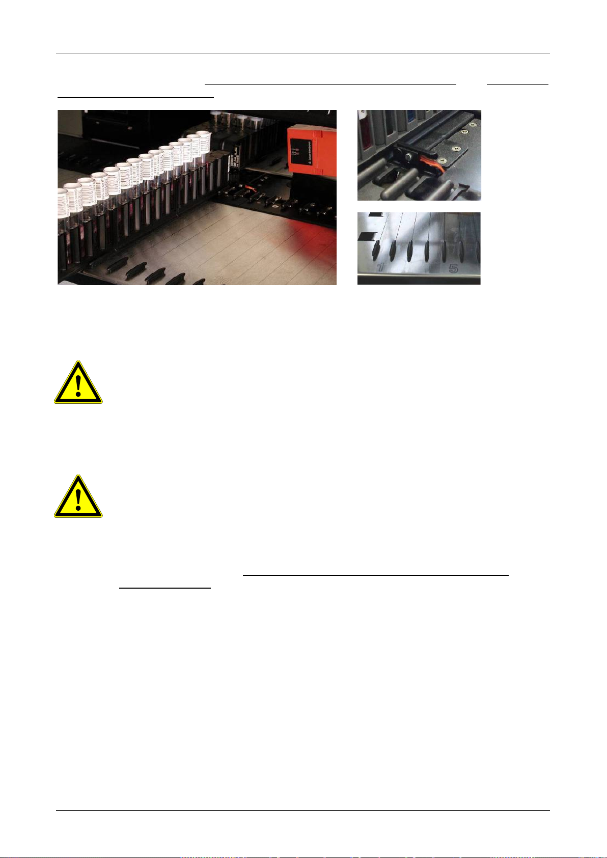
Insert the carriers into the tracks between the front and rear slide blocks of the Loading Tray until
they touch the stop hooks on the far side of the tray (see
Carriers).
®
AM16 in conjunction with the AltoStar® Connect SW was developed to control
®
AM16 by altona Diagnostics GmbH. Therefore, the information given in this
®
Purification Kit and the AltoStar® Internal Control and
Fig. 1.: Slide Blocks and Stop Hooks for
Do not exchange positions of sample or reagent tubes or switch microplates after they have been
identified by the barcode reader. This could result in incorrect test data or instrument crash.
Microplates must be placed on the carrier such that well A1 is on the left side.
When loading reagents, ensure that there is no foam on the surface of the liquid.
NOTE
problems.
Do not overfill sample tubes.
Do not mix tip sizes in the same tip rack.
Do not fill up tip racks with tips from another rack. Tips should be loaded in the tip racks as they
are provided in the original packaging. They are individually labeled with a barcode for
identification.
4 627108_00
Page 11
AltoStar® Automation System AM16 – OPERATOR’S MANUAL IVD
Make sure the carriers are inserted completely until they touch the stop hooks
Make sure there are no carriers loaded on the same tracks as already loaded
AM16 and the
Purification Kit 1.5 and the
track carrier (such as a sample carrier) with particular care, as
ype of carrier can fall over and cause injury or contamination. Position it
For further information see Chapter 3.2 Starting the AltoStar® Connect SW and Chapter 3.3
AltoStar® Workflow: Purification.
Fig. 1.: Slide Blocks and Stop Hooks for Carriers
ATTENTION
on the Loading Tray.
carriers on the deck.
ATTENTION
Ensure that there is no foam on the surface of reagents.
Do not manipulate the filling volumes of reagent containers or tubes.
Handle consumables and reagents with care to avoid spilling liquids.
Only use consumables specified for use with the AltoStar®
AltoStar® reagents (see manuals of the AltoStar®
AltoStar® PCR kits).
Position Eluate Plate and PCR Plate correctly such that well A1 is placed to
the left side.
Handle any 1this t
on the Loading Tray, or place several carriers together to minimize this risk.
627108_00 5
Page 12

AltoStar® Automation System AM16 – OPERATOR’S MANUAL IVD
1.5.1.5 Work Routine
Periodic maintenance (daily maintenance, weekly maintenance, six-monthly maintenance) is a
mandatory part of the work routine.
User access to the cabinets underneath the instruments during a run may interfere with automatic
loading and unloading of carriers (the carriers protrude).
Discard used tips and do not reuse them. Do not empty the tip waste during a run.
Do not try to open the front cover during a run. It may cause an abort of the run.
Do not leave tips on the pipetting channels for a long period of time (say, overnight). This may
cause damage to the CO-RE O-rings. A daily maintenance procedure will remove the tips.
1.5.2 Biohazard Precautions
If the AltoStar® AM16 becomes contaminated with bio-hazardous or chemical material, it should be
cleaned in accordance with the maintenance procedures (see Chapter 4 Maintenance
and carry out the maintenance procedures given. Failure to do so may impair the reliability and
correct functioning of the AltoStar
®
AM16.
If wor k ing with bio-hazardous samples, observe and carry out the maintenance procedures, paying
particular attention to cleaning and decontamination. Wear gloves when handling the pipetting arm
and channels, the carriers, racks, containers and tips.
). Obs erve
Avoid touching tips discarded into the waste container. Any surfaces on which liquid is spilled must
be decontaminated.
Do not use disinfecting materials, which contain hypochlorite (Javel water, Chlorox) or bleaching
fluids.
If working with bio-hazardous or chemical materials, the user must not touch them. The AltoStar
®
AM16 will drop its used tips into a waste container, that should be emptied during the daily
maintenance or as soon as it is full.
1.5.3 Computer Precautions
Use the necessary precaution to guard against software viruses. Any manipulation of AltoStar®
AM16 data files or other information determining or affecting AltoStar
erroneous test results or instrument failure.
®
Only the AltoStar
Connect SW may be used to control the AltoStar® AM16.
For reasons of data security and integrity, use of an Uninterruptible Power Supply (UPS) is
recommended, since a loss of power may cause data to be lost or corrupted.
To avoid computer breakdowns, ensure that there is always enough storage capacity on your hard
drive. Archive the log files from time to time.
For further information regarding the computer and the software installation refer to
Computer Requirements and the AltoStar® Connect Software Manual IVD.
®
AM16 functions can result in
Chapter 2.3
1.5.4 Hazards
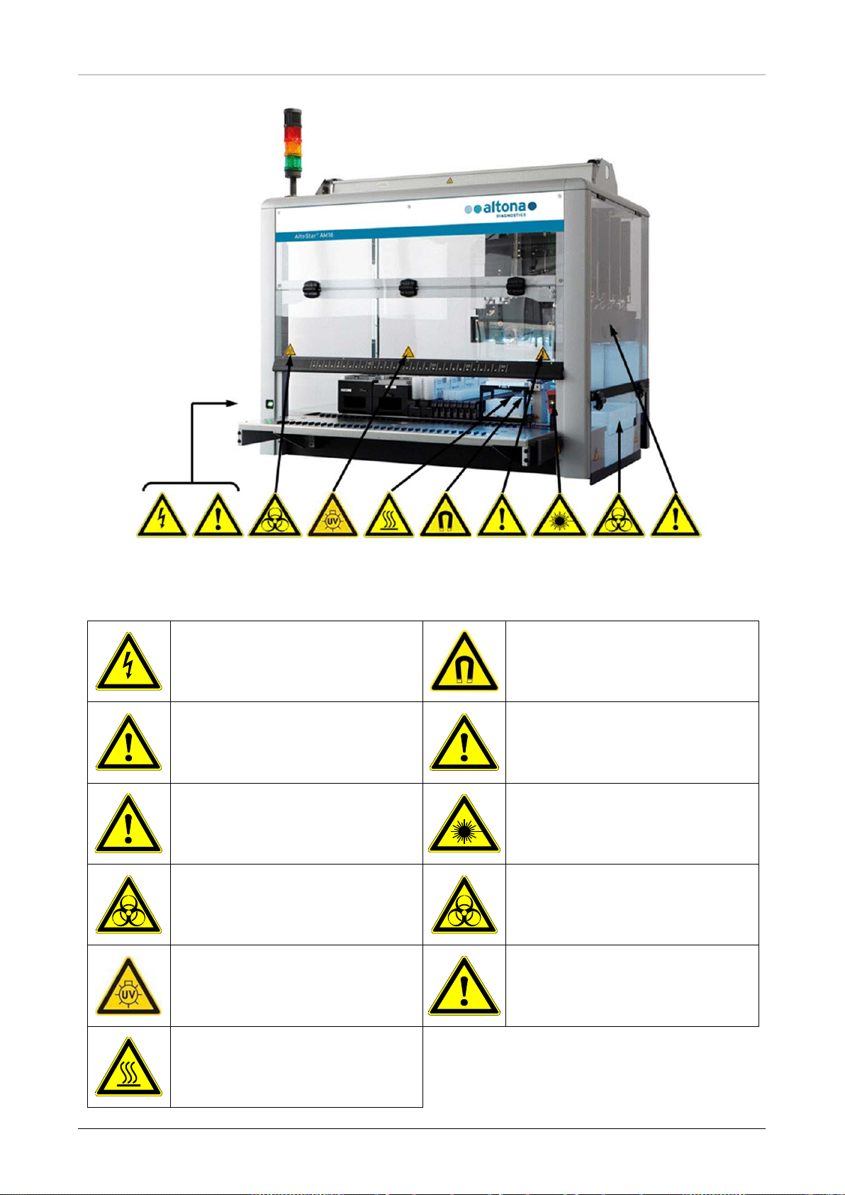
Location and explanation of warning and attention labels:
6 627108_00
Page 13
AltoStar® Automation System AM16 – OPERATOR’S MANUAL IVD
®
Fig. 2.: AltoStar
AM16 with the Location of Warning and Attention Labels
Table 1: Explanation of Warning and Attention Labels
Power Connection
Connect only to earth-grounded outlet
Connection to PC
Use only the appropriate shielded cables
USB Connection
At a total cable length of more than 5 m,
signal loss may occur
Biohazard Warning
Deck may contain bio-hazardous or
chemically contaminated mate rials
Strong Magnetic Field (Magnetic Bead
Separation Block)
Interaction with metallic objects may
produce Pinch Hazards. Pacemaker
wearers stay back 30cm.
Moving Parts
Moving arm inside transparent cover.
Aborts the run if cover is opened.
Laser Beam (Autoload)
Do not stare into beam of class 2 laser of
the barcode reader
Biohazard Warning
Waste may contain bio-hazardous or
chemically contaminated mate rials
UV Lights
Avoid exposure to UV light. Exposure may
cause severe eye or skin injury. Wear a
suitable face shield, gloves and protective
clothing.
Hot Surface
Avoid contact of HHS. Surfaces are hot
and may cause personal injury if touched
627108_00 7
X-Arm
Do not move X-Arm by hand
Page 14
AltoStar® Automation System AM16 – OPERATOR’S MANUAL IVD
Rapid temperature changes or direct sunlight may affect certain functions such
intense artificial light
1.5.4.1 Safety Measures
• Access to Power Switch/Power Cord
Ensure there is enough room to access the power switch and power cord.
• Working Area
The safety concept assumes that the doors are always closed and locked during normal
operation.
• Surrounding Area
Make sure the ventilation outlets of the instrument are not impaired by obstacles placed in the
surrounding area.
ATTENTION
as barcode reading and pipetting accuracy.
• Do not open windows next to the instrument
• Do not expose the instrument to direct sunlight or
during operation
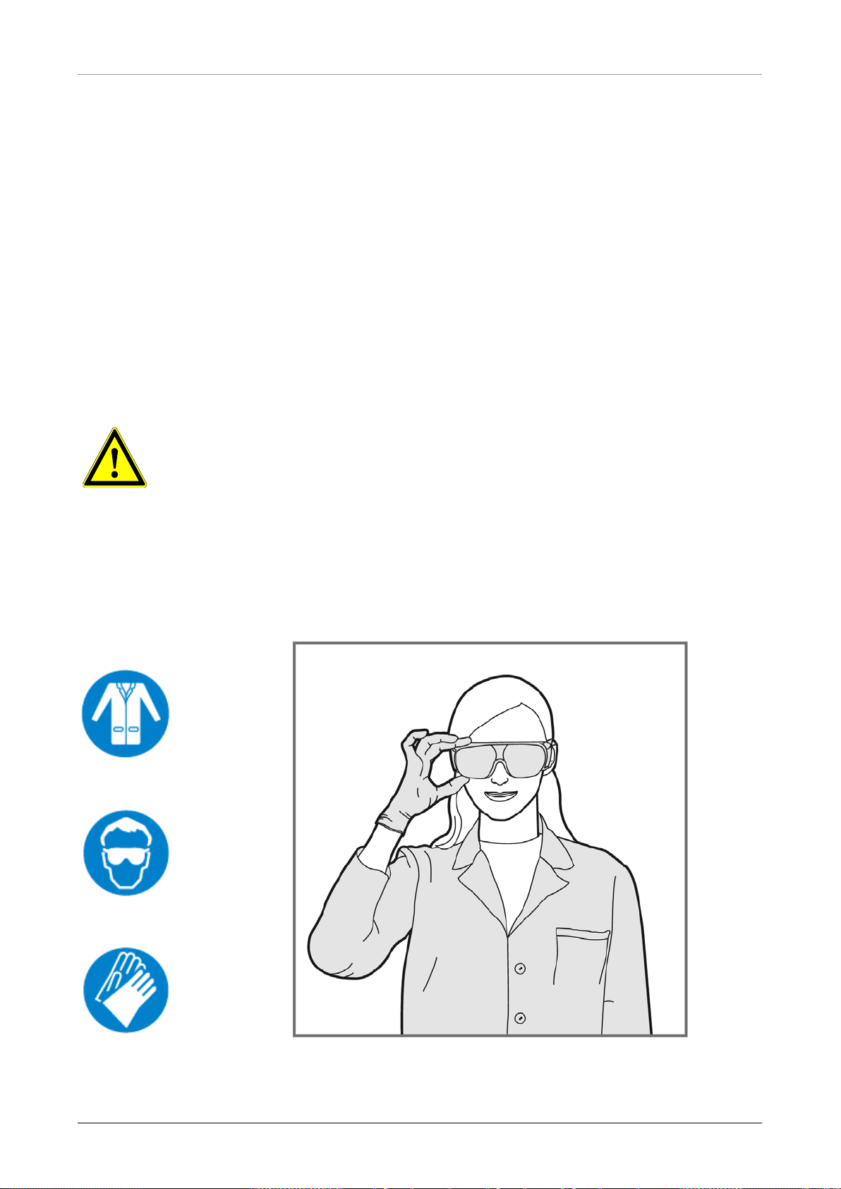
Use appropriate:
Protective clothing
Goggles
and Gloves.
8 627108_00
Page 15
AltoStar® Automation System AM16 – OPERATOR’S MANUAL IVD
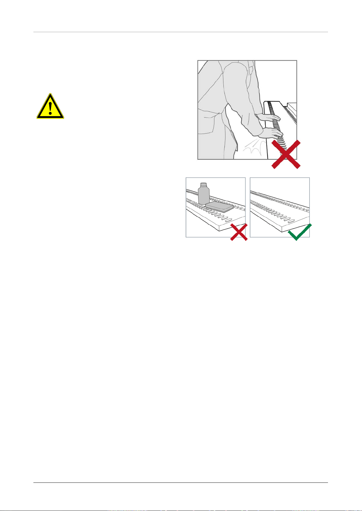
1.5.4.2 Loading Tray
Loading Tray:
• The instrument loading tray is a part of the
instrument and must be treated with care
ATTENTION
Risk of damage to equipment.
Leaning onto the instrument
loading tray will lead to damage
of the loading tray.
• Do not lean onto the loading
tray.
Foreign object damage:
• Make sure that the loading tray has been
cleared from foreign objects before
running the instrument
• Foreign objects may obstruct the
instrument and lead to damage to the
equipment
627108_00 9
Page 16
AltoStar® Automation System AM16 – OPERATOR’S MANUAL IVD
2 Description of the AltoStar® AM16
The AltoStar® AM16 is a robotic pipetting workstation used for sample purification and PCR setup
controlled by the AltoStar
®
Connect SW.
2.1 AltoStar® AM16 Instrument
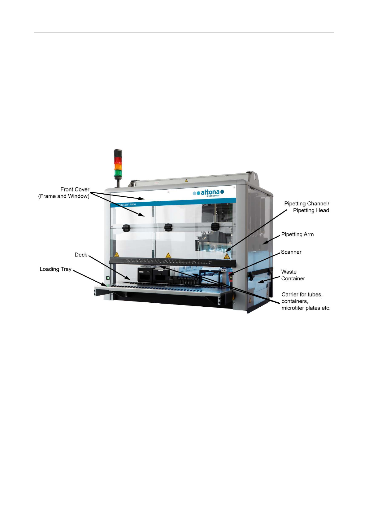
The AltoStar® AM16 wor k surface is called a ‘deck’, for placing loadable carriers. These carriers
hold reagent containers, such as tubes, microplates, and other kinds of labware.
Fig. 3.: AltoStar® AM16 Instrument
The instrument deck is divided into equal tracks (T) for loading carriers in pre-determined positions.
This eliminates the need for precise measurement of positions. The deck has partitions of 22.5 mm,
which is equivalent to 1-T (track). The labware carriers are adapted to those partitions.
An additional partition provides space for the tip waste container.
10 627108_00
Page 17
AltoStar® Automation System AM16 – OPERATOR’S MANUAL IVD
Container
2.1.1 Liquid Waste
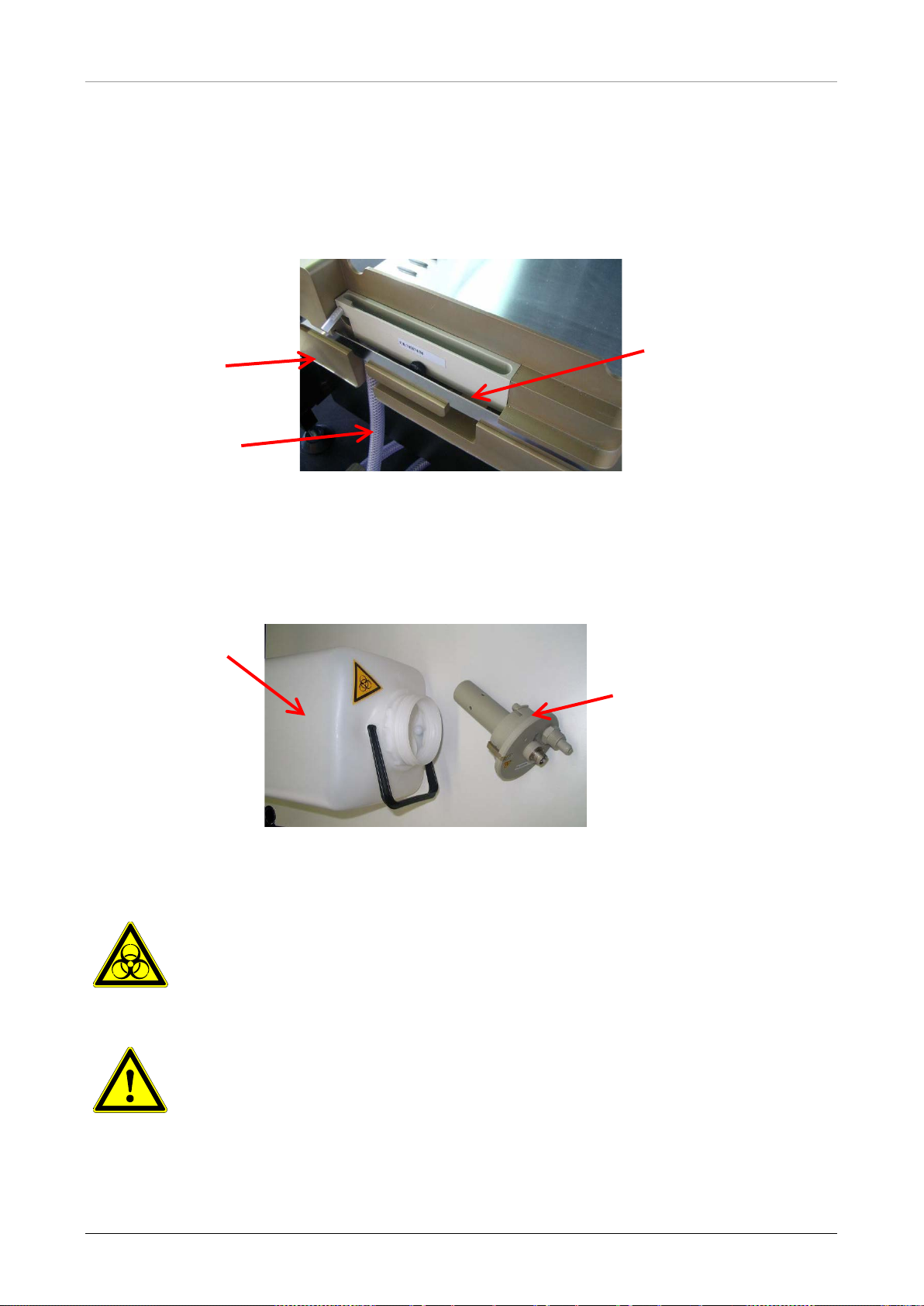
Description of the Liquid Waste:
To avoid liquid waste accumulation in the waste station, the liquid waste is disposed separately
into the Liquid Waste. The collection tray for the liquid waste is located underneath the (slotted) Tip
Eject Sheet on the waste block. From this collection tray, the liquid waste flows into a monitored
liquid waste container, located underneath the instrument.
Collection Tray
Overflow into
Waste Station
Tubing to Liquid
Waste Container
Fig. 4.: Description of the Liquid Waste
Before the tips are discarded into the tip waste, the remaining liquid will be drained into the liquid
waste. An overflow will prevent overfilling of the collection tray if the main tubing is clogged. An
overflowing liquid is passed into the liquid waste, preventing contamination of the deck.
Liquid Waste
Cap with Liquid Level
Detection
Fig. 5.: Liquid Waste Container and Cap with Liquid Level Detection
Biohazard Warning
Liquid Waste may contain bio-hazardous or chemically contaminated materials
ATTENTION
Dispose of hazardous and biological waste in compliance with local and national
regulations. The product should not be allowed to enter sewage, water courses
or the soil.
627108_00 11
Page 18
AltoStar® Automation System AM16 – OPERATOR’S MANUAL IVD
The Liquid Waste contains a cap presence sensor. The cap, using its liquid level detection sensor,
can monitor the fill level status. The liquid level detection sensor will give a “full” signal if the fill
level is reaching approximately 80 % of the container’s capacity (4.8 l). The fill level status is
automatically checked before each run, preventing the start of a run if the container’s residual
capacity is below approximately 20 %. In absence of this signal, the residual capacity is sufficient
for a full run.
2.1.2 UV Kit
The UV Kit has been developed in order to offer the possibility of UV decontamination of the
AltoStar
®
AM16 workspace. The required duration and frequency of the UV decontamination
process is dependent on the substances used on the instrument and the user is responsible to
choose the appropriate duration and frequency.
®
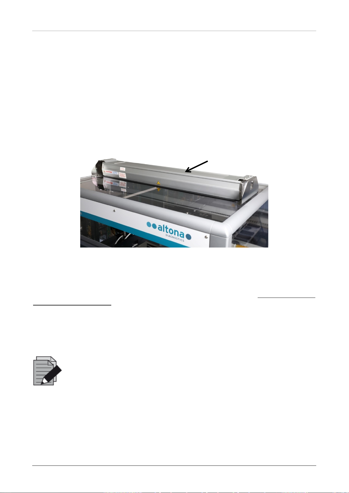
Fig. 6.: UV Light on top of the AltoStar
AM16
®
The UV Kit must be used with the AltoStar
Connect SW.
For detailed information regarding the UV decontamination process refer to
Chapter 6 AltoStar®
AM16 UV Decontamination. T he UV Kit is n ot suitable for decontamination of accessories such as
carriers, modules, etc. as the UV (ultra-violet) light cannot reach all surfaces of such complex
structures.
If the UV Kit is used in a manner not specified, the protection provided by the equipment may be
impaired.
NOTE
®
The UV Kit is only intended to be used in combination with the AltoStar
A stand-alone operation of the UV Kit is not foreseen.
AM16.
The UV Kit components bear the following labels
12 627108_00
Page 19
AltoStar® Automation System AM16 – OPERATOR’S MANUAL IVD
Avoid exposure to UV light. Exposure may cause severe eye or skin injury.
The red
signal may or may not be accompanied by a warning sound
Hot Surface
Avoid contact with the UV light. Surfaces are hot and may cause personal injury
if touched.
UV Light
Wear a suitable face shield, gloves and protective clothing.
2.1.3 Signal Light
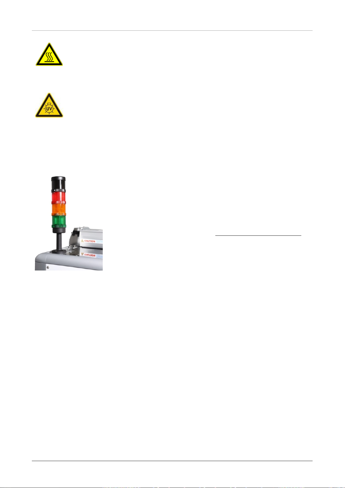
A Signal Tower on top of the AltoStar® AM16 visually and audibly indicates the operating states of
the system.
The green light indicates normal processing of the AltoStar
®
AM16.
The orange light indicates that a user interaction with the system is
required.
The red light indicates aborting the run due to an error.
depending on the system settings of the AltoStar® Connect SW.
For further information refer to the AltoStar® Connect SW Manual.
Fig. 7.: Signal-Light on top of the AltoStar® AM16
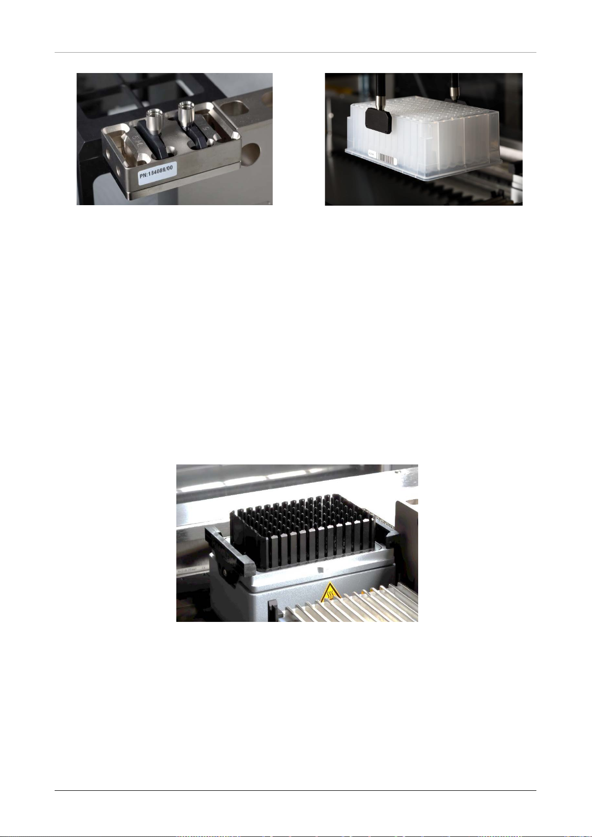
2.1.4 CO-RE Gripper
The CO-RE Gripper is the plate handling tool picked up by two pipetting channels during a run.
®
The CO-RE Gripper transports the AltoSt ar
the AltoStar
®
AM16.
Processing Plate between positions on the deck of
627108_00 13
Page 20
AltoStar® Automation System AM16 – OPERATOR’S MANUAL IVD
Fig. 8.: CO-RE Gripper Holder with Jaws
for the 1000 µl Pipetting Channels (inner
positions)
Fig. 9.: Plate Being Moved with CO-RE
Gripper using 1000 μl Pipetting
Channels
2.1.5 HAMILTON Heater Shaker
The HAMILTON Heater Shaker (HHS) is used to heat and shake the AltoStar® Processing Plate.
Loading and unloading, as well the independent heating or shaking function of the HHS is fully
controlled by the AltoStar
Before shaking, the plates are locked and positioned in the center of the HHS. When the shaking
process has finished, the plates are unlocked and can be easily removed from the HAMILTON
Heater Shaker by the CO-RE Gripper (do not move/remove plates manually from the HHS).
The HHS adapter fitted to the AltoStar
heating performance, two sensors permanently control the temperature which guarantees the
abidance of the set temperature range. In addition, a cut-off temperature will protect from overheating.
®
Connect SW.
®
Processing Plate allows optimal heating. To ensure reliable
Fig. 10.: HHS with Adapter for AltoStar® Processing Plate
14 627108_00
Page 21

AltoStar® Automation System AM16 – OPERATOR’S MANUAL IVD
Do not touch the HHS while running, and shortly after finishing a run, as it might be
hot. Wait until the HHS has cooled down to room temperature, which can take up to 1
Make sure that the plate used with the HHS is heat resistant (maximum temperature
ATTENTION
hour.
Flammable liquids must not be heated by the HHS as they might cause fire.
105°C).
627108_00 15
Page 22
AltoStar® Automation System AM16 – OPERATOR’S MANUAL IVD
Interaction with metallic objects may produce Pinch Hazards. Pacemaker wearers
Carrier barcode label at the back of the carrier with
P0100001
PLT_CAR_5LMD_A00
182580/01
2.1.6 Magnetic Stand
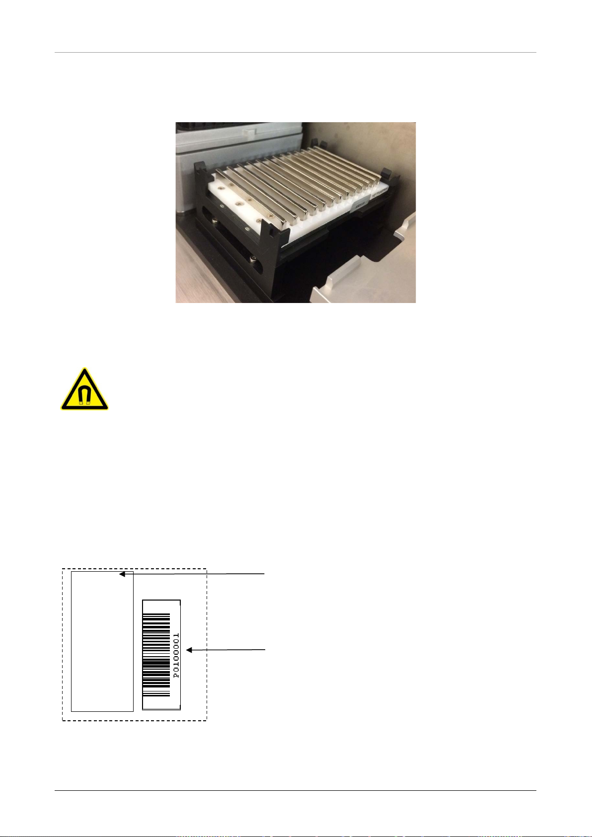
The Magnetic Stand is used to collect the magnetic beads at the bottom of the AltoStar®
Processing Plate.
Fig. 11.: M agnetic Stand for AltoStar
®
Processing Plate
ATTENTION
Strong Magnetic Field (Magnetic Bead Separation Block)
stay back 30 cm.
2.2 Carriers
Labware is placed on special carr iers which are loaded onto the AltoStar® AM16 instrument deck.
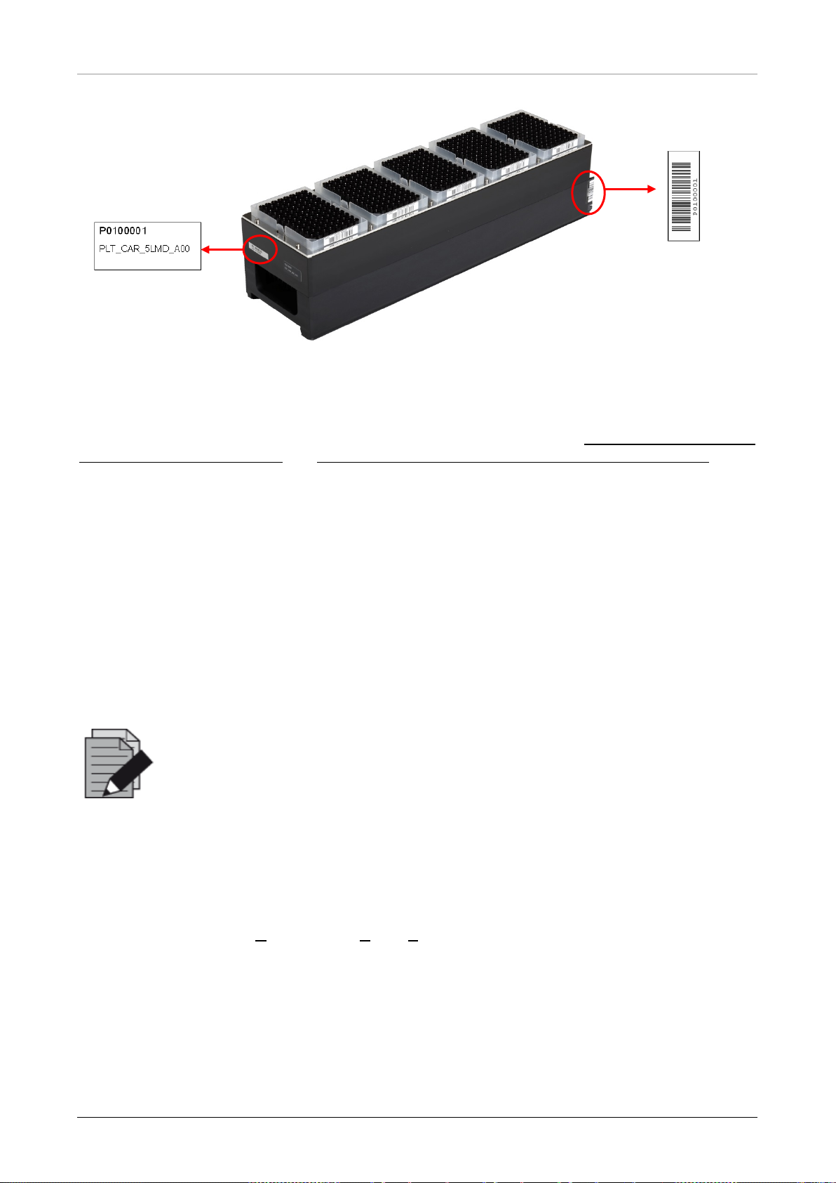
Every carrier is equipped with at least 2 labels, one identification label and one barcode label. The
identification label is readable by the operator; it contains the carrier name and barcode information.
The carrier name on the identification label is the one used by the AltoStar
The barcode label is for purposes of automatic identification.
Identification label on the front side of the carrier:
• carrier identification number
• carrier name
®
AM16 Software.
Fig. 12.: Carrier Barcode Labels
16 627108_00
carrier identification number:
• char acter 1 to 3: carrier type
• the rest is serial numbering
Page 23
AltoStar® Automation System AM16 – OPERATOR’S MANUAL IVD
installation to
abel
Identification Label
on the Front
Carrier Barcode L
at the Back
Fig. 13.: 1000 µl Tip Carrier
For more information regarding the used carriers and loading please see
Chapter 3.3.5 Instrument
Loading for a Purification Run and Chapter 3.4.3 Instrument Loading for the PCR Setup Run.
2.3 Computer Requirements
The AltoStar® AM16 and its accessories are controlled by the dedicated AltoStar® Connect SW
which controls all functions for daily work routine, running purification runs and PCR setup runs
and other services.
The computer running the AltoStar
use a different computer for the operation of the AltoStar
®
The AltoStar
AM16 and the computer are linked via Universal Serial Bus interface (USB).
To avoid data loss, we recommend an uninterruptible power supply (UPS) for the PC.
NOTE
Use password protected user accounts in the Microsoft Windows®
prevent unauthorized access.
®
Connect SW is delivered by altona Diagnostics GmbH. Do not
®
AM16.
2.4 Power / Voltage
Make sure that the AltoStar® AM16 is connected to a 115 or 230 VAC (50Hz or 60Hz) socket. The
AltoStar
We recommend using an Uninterruptible Power Supply (UPS) for the AltoStar® AM16.
Ensure that the instrument is correctly grounded when connected to the power supply.
The main plug is on the left-hand front side of the instrument.
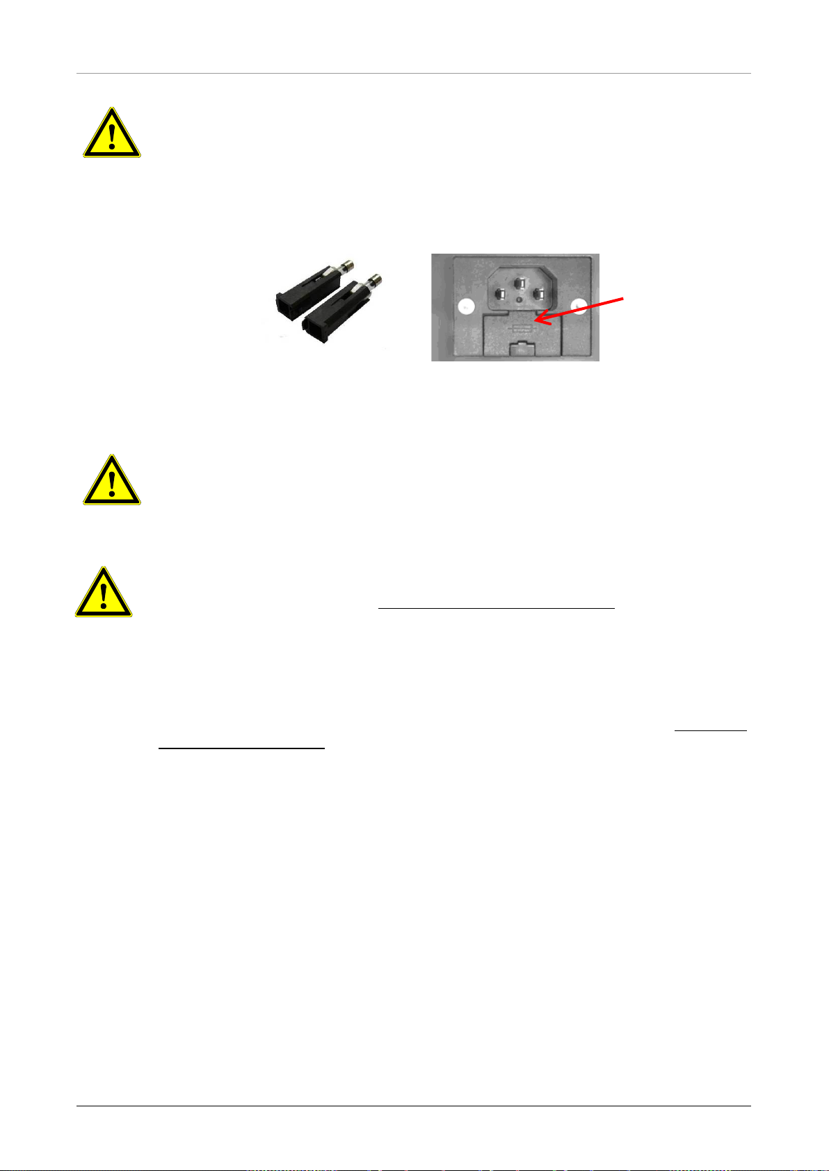
The fuses for the instrument are placed in the main power socket (see picture below).
During installation / IQ, the appropriate fuse is selected by the trained field service engineer.
Plug the main cables for the computer and the instrument into the same electrical outlet. Connect
them only to a grounded outlet.
627108_00 17
®
AM16 automatically recognizes any voltage within that range, without user intervention.
Page 24
AltoStar® Automation System AM16 – OPERATOR’S MANUAL IVD
n case of damage or loss of
. If replacing
cords, the protection provided by
When replacing a fuse, make sure to use the appropriate fuse and place it into
) in the ma in pow er
Do not exchange the supplied/installed power cord. In case of damage or loss of the
Diagnostics GmbH for a replacement. If replacing the
power cord by inadequately rated power cords, the protection provided by the
Chapter 8
place it into the main power switch before switching on
ATTENTION
Do not exchange the supplied/installed power cord. I
the power cord, contact altona Diagnostics GmbH for a replacement
the power cord by inadequately rated power
the equipment may be impaired.
Fuses
Fuse Holders
Fig. 14.: M ain Power Socket with Appropriate Fuses
ATTENTION
the main power switch before switching on the instrument.
ATTENTION
Place the appropriate fuse (see Chapter 8 Technical Specifications
switch before switching the instrument on.
power cord, contact altona
equipment may be impaired.
When replacing a fuse, make sure to use the appropriate fuse (see
Technical Specifications) and
the instrument.
18 627108_00
Page 25

AltoStar® Automation System AM16 – OPERATOR’S MANUAL IVD
installation to
3 AltoStar® Connect SW
The AltoStar® Connect SW comes preinstalled on a computer provided by altona Diagnostics
GmbH.
It is the sole responsibility of the user to ensure sufficient protection against:
• Unauthorized access to the computer via computer network.
• Unauthorized local access to the software. Use password protected user accounts in t he
Microsoft Windows® installation to prevent unauthorized access.
• Software viruses and malware.
• Power outage and voltage fluctuation. For reasons of data safety and integrity, use of an
Uninterruptible Power Supply (UPS) is recommended, since a loss of power or voltage
fluctuations may cause data to be lost or corrupted and runs to abort.
NOTE
Use password protected user accounts in the Microsoft Windows®
prevent unauthorized access.
®
The Alt oSt ar
system. With the AltoStar
Connect SW has a graphical user interface that enables the user to interact with the
®
Connect SW the user can:
• Manage the system settings (depending on user account privileges)
• Manage the purification and assay protocols (depending on user account privileges)
• Perform instrument maintenance
®
• Perform an AltoStar
workflow run consisting of:
o Programming a run
o Performing a sample purification run
o Viewing sample purification results
o Performing a PCR setup run
o Viewing PCR setup results
o Transfer of the PCR plate and run information to the connected real-time PCR
cycler.
• Perform a Sample Transfer workflow run consisting of:
o Programming a run
o Performing a sample transfer run for purification on an external purification
instrument
o Viewing sample transfer results
o Performing a PCR setup run with eluates from the external purification instrument
o Viewing PCR setup results
o Transfer of the PCR plate and run information to the connected real-time PCR
cycler.
627108_00 19
Page 26

AltoStar® Automation System AM16 – OPERATOR’S MANUAL IVD
Windows® user group
Perform an AltoStar® workflow run
• Perform an External Purification workflow run consisting of:
o Programming a run
o Performing a PCR setup run with eluates from an external purification instrument
o Viewing PCR setup results
o Transfer of the PCR plate and run information to the connected real-time PCR
cycler.
3.1 User Accounts
The AltoStar® Connect SW can be used from different user accounts created in the Microsoft
Windows
®
operating system of the computer that runs the AltoStar® Connect SW. The computer is
delivered with the two user accounts ‘Laboperator’ and ‘Labadmin’ preinstalled. These accounts
have different privileges:
Table 2: User Accounts
Laboperator Labadmin
Lab Operator Lab Service
Perform instrument maintenance
Perform a Sample Transfer workflow run
Perform an External Purification workflow
run
Manage the System Settings X
Manage the Purification and Assay
protocols
®
It is recommended to create one Windows
user account per user to ensure traceability. The
Windows user account used for a workflow run is traced in the run report files.
®
When creating a user account in Windows
, it has to be associated with a specific Windows® user
group to grant the privileg e s illustrated in Table 2: User Accounts.
To grant the privileges of a normal user, add the new Windows
user group ‘Lab Operator’ in the Windows
To grant the privileges of an administrator, add the new Windows
user group ‘Lab Service’ in the Windows
®
‘Local Users and Groups management’ (lusrmgr.exe).
®
‘Local Users and Groups management’ (lusrmgr.exe).
✔ ✔
✔ ✔
✔ ✔
✔ ✔
✔
X
®
user account to the W indows®
®
user account to the Windows®
✔
For further information and assistance, contact altona Diagnostics GmbH.
20 627108_00
Page 27
AltoStar® Automation System AM16 – OPERATOR’S MANUAL IVD
3.2 Starting the AltoStar® Connect SW
To start up the system, switch on the AltoStar® AM16 instrument and the computer t hat runs the
AltoStar
®
Connect SW. The order in which the instrument and the computer are started is
irrelevant.
Turn on the instrument with the front left green switch and start the computer by pressing the
power button.
®
Once Windows
desktop, the Windows task bar or in the Windows
has booted, start the AltoStar® Connect SW using the a* icon on the Windows®
®
start menu.
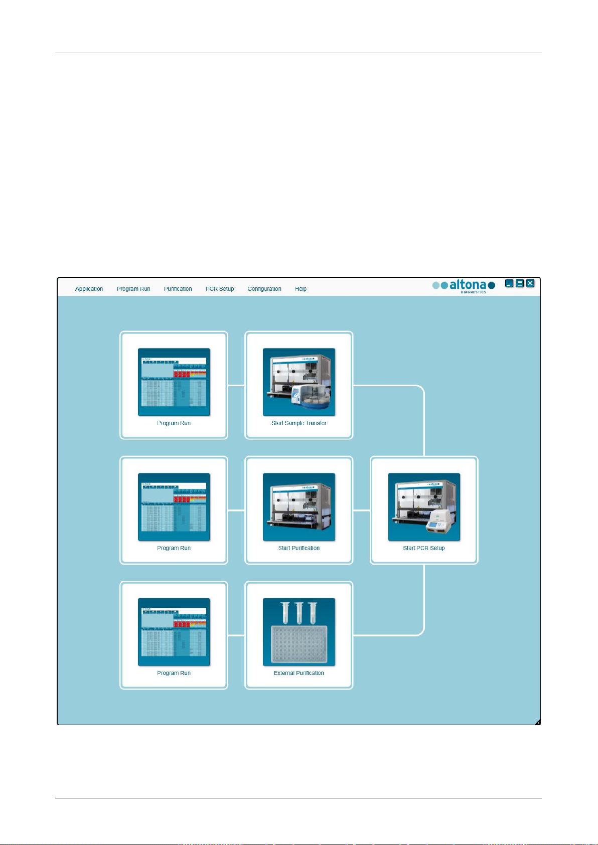
The software opens and displays the start screen. The start screen depicts the available workflow
options as set in the system settings. The boxes depict the discrete stages of each workflow and
can be clicked to access the respective user interface.
Fig. 15.: Start Screen of the AltoStar
627108_00 21
®
Connect SW
Page 28
AltoStar® Automation System AM16 – OPERATOR’S MANUAL IVD
1. No
alterations to the programmed process are possible in later phases of the
ensure that all required material and devices are
3.3 Workflows
®
The AltoStar
and the PCR setup process. The purification can be performed in one of three workflow options:
• On the AltoStar
(AltoStar Workflow)
• On an external purification instrument with the AltoStar
samples from the sample tubes to the processing plate of the external purification
instrument (Sample Transfer Workflow)
• On an external purification instrument without sample transfer on the AltoStar
instrument (External Purification Workflow)
Connect SW facilitates the processing of samples through the sample purification
®
AM16 instrument in conjunction with the AltoStar® Purification Kit 1.5
®
AM16 instrument transferring the
®
AM16
Regardless of the chosen purification workflow option, the PCR setup procedure is the same and is
performed on the AltoStar
®
AM16 instrument for all three purification options. The following
chapters will illustrate the processing of the AltoStar workflow purification and the PCR setup
process.
For further information regarding the processes illustrated here and the Sample Transfer and
External Purification workflows refer to the AltoStar
®
Connect Software Manual IVD Chapters 3.9:
Sample Transfer Workflow: Purification and 3.10: External Purification Workflow: Purification.
3.4 AltoStar® Workflow: Purifica ti on
The Alt oSt ar® Connect SW facilitates the processing of the AltoStar® Workflow: Purific atio n on the
AltoStar
1. Programming of the complete workflow process for a fixed set of samples in the AltoStar®
2. Specimen preparation: Refer t o the AltoStar® Purification Kit 1.5 Manual for instructions
3. Sample purification on the AltoStar® AM16 as programmed in step 1.
4. PCR setup on the AltoStar® AM16 as programmed in step 1.
5. PCR on a CFX 96™ DW as pr ogr amm ed in step 1. (r efe r t o r es pect iv e altona Diagnostics PCR
®
AM16 instrument. The workflow consists of the following sequential steps:
Connect SW.
Kit Manual)
For further information, please see the AltoStar® Connect Software Manual IVD.
NOTE
The programming for the complete workflow process is concluded in step
workflow.
NOTE
Before starting the workflow,
available.
22 627108_00
Page 29
AltoStar® Automation System AM16 – OPERATOR’S MANUAL IVD
ensure that the Daily and Weekly Maintenance
annual maintenance and verification
instrument will not process any
samples or reagents. It is recommended to conduct the Daily Maintenance when
the device is turned on the first time each day and to conduct the Weekly
down of the system. The
aintenance routine verifies the correct functionality of the instrument and will
Ensure that the last four Lot Number digits of all Lysis Buffer, Wash Buffer,
Magnetic Bead, Enhancer and Elution Buffer containers used in a run are
during loading and instructs the
these four digits are displayed as
NOTE
Before starting the workflow,
have been conducted and that the semiprocedure is not overdue. Otherwise. the
Maintenance at the end of the week before shutm
prompt necessary user actions including cleaning of the instrument.
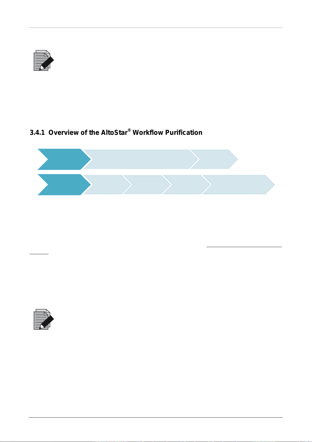
3.4.1 Overview of the AltoStar® Workflow Purification
Program a
Run
Purification
Input samples and PCR assay assignment or
import from LIMS
Prepare
Samples
Start
Purification
Load
reagents
and samples
Create Run
Unload samples and
reagents after
purification
Fig. 16.: Overview of the AltoStar
®
Workflow Purification
3.4.2 Sample Preparation
For preparation and pretreatment of samples, please refer to the AltoStar® Purification Kit 1.5
Manual.
3.4.3 Preparing Reagents for a Purification Run
All reagent containers are barcoded for automated identification, localization and verification of lot
conformity and non-expiry by the AltoStar
®
system.
NOTE
identical. The software verifies lot conformity
user accordingly. For your convenience,
Loading Number on the outside of each component box.
627108_00 23
Page 30
AltoStar® Automation System AM16 – OPERATOR’S MANUAL IVD
Purification Kit 1.5 reagents are not expired. During
loading the software verifies use within the shelf life of the reagents and instructs
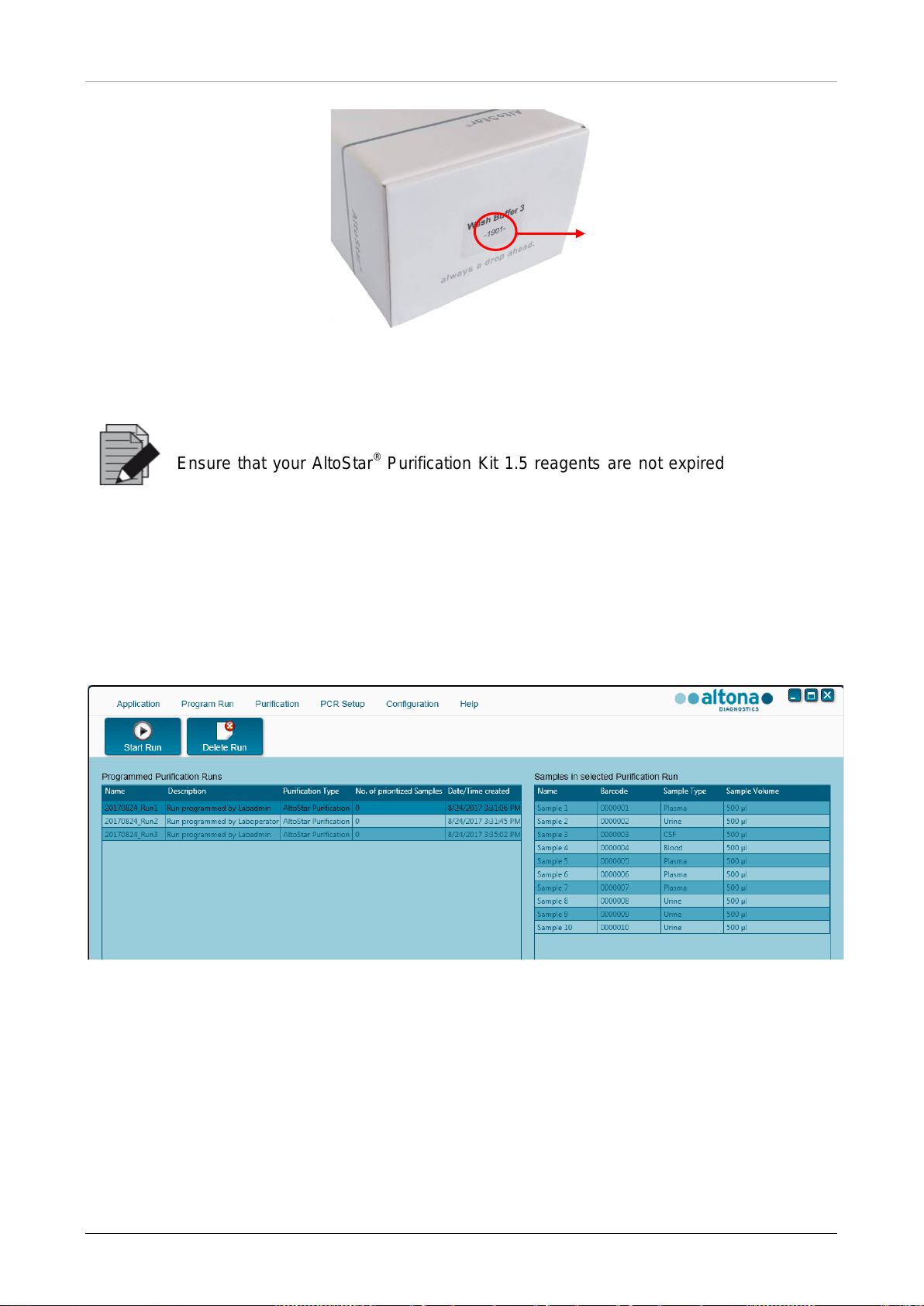
Loading Number
Fig. 17.: Side View of the Box with the Loading Number
NOTE
Ensure that your AltoStar®
the user accordingly.
3.4.4 Starting a Purification Run
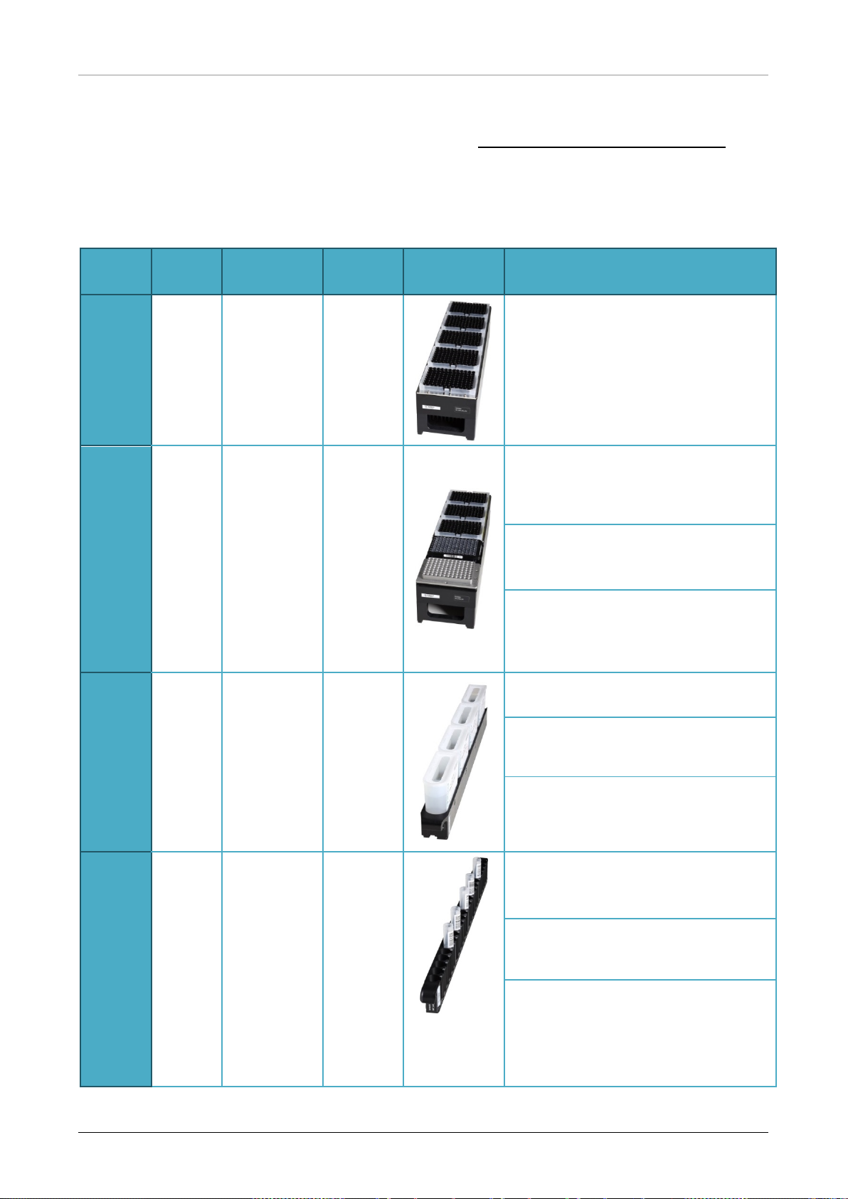
To start the purification run, g o back to the Start Window of the AltoStar® Connect SW and select
Start Purification or select Purification
run definitions are displayed in the Programmed Purification Runs t able on the left side of the
screen.
Fig. 18.: St art Run Screen
→ Start Purification in the menu bar. Your purification
• Select the purification run definition to be started in the Programmed Purification Runs
table
• The samples included in the selected run definition are displayed in the table on the right
side of the screen (Samples in selected Purification Run)
• Click the Start Run button in the tool bar
24 627108_00
Page 31

AltoStar® Automation System AM16 – OPERATOR’S MANUAL IVD
Click Delete Run to completely delete the selected programmed purification run. By clicking
Delete Run all associated programmed PCR Setup runs will also be deleted.
627108_00 25
Page 32
AltoStar® Automation System AM16 – OPERATOR’S MANUAL IVD
The position of the individual tubes on
3.4.5 Instrument Loading for a Purification Run
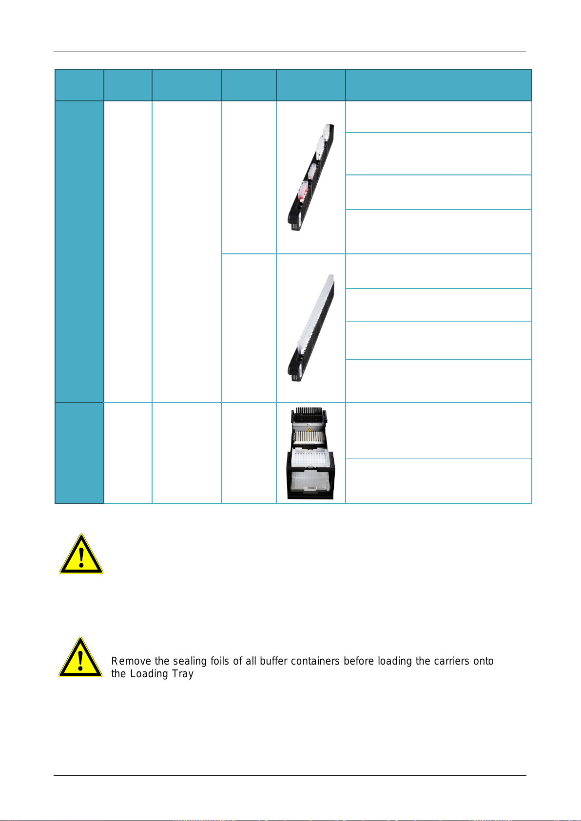
At the start of a run the Loading dialog is displayed (see Fig. 19.: Purification Loading Dialog). The
material, reagents and samples have to be loaded onto suitable carriers, before these carriers can
then be loaded onto the respective tracks on the Loading Tray of the instrument:
Table 3: Carrier Description for Purification Run
Carrier
No.
1
2
Track Material
1 - 6
5 racks of
1000 µl tips
3 racks of
7 - 12
300 µl tips 1
Elution Plate
Carrier
Name
Tip
Carrier
Tip and
Plate
Carrier
Image Notes
Only exchange completely empty Tip
Racks for completely full ones. Do not
handle individual tips.
Only exchange completely empty Tip
Racks for completely full ones. Do not
handle individual tips.
Always place plates with well A1 to
the left of the respective plate
position.
For PCR-Setup, the PCR plate must
be placed at the front position and the
Eluate plate at the second front
position.
3-4
5
13-16
17
Up to four
Lysis Buffer
and Wash
Buffer
containers
per carrier
Up to 24
Internal
Control,
Magnetic
Bead,
Enhancer
and Elution
Buffer tubes
Container
Carrier
Tube
Carrier 24
One or two carriers can be loaded.
The position of the individual
containers on the carriers is arbitrary.
Gently push the containers down all
the way to the bottom of the carrier.
the carrier is arbitrary.
Ensure all tube barcodes are visible
through the carrier windows.
Gently push the tubes down all the
way to the bottom of the carrier.
26 627108_00
Page 33
AltoStar® Automation System AM16 – OPERATOR’S MANUAL IVD
The position of the individual tubes on
The position of the individual tubes on
Remove the lids of all tubes before loading the carriers onto the Loading Tray.
Leaving them on may lead to false results, aborted runs and damage to the
avoid contamination. Reuse the
Remove the sealing foils of all buffer containers before loading the carriers onto
the Loading Tray. Leaving them on may lead to false results, aborted runs and
he instrument. Dispose of the sealing foils. To close the buffer
Carrier
No.
6 - 11
Track Material
Up to 96
samples on
18 - 23
any
combination
of these two
carrier types
Carrier
Name
Tube
Carrier 24
Tube
Carrier 32
Image Notes
Up to 24 sample tubes of 14.5 mm 18 mm diameter per carrier.
the carriers is arbitrary.
Ensure all tube barcodes are visible
through the carrier windows.
Gently push the tubes down all the
way to the bottom of the carrier.
Up to 32 sample tubes of 11 mm - 14
mm diameter per carrier.
the carriers is arbitrary.
Ensure all tube barcodes are visible
through the carrier windows.
Gently push the tubes down all the
way to the bottom of the carrier.
This carrier is not removable and is
12
24 - 30
1 Processing
Plate
1 Tip Park
Plate
1 Tip Park
Rack
Heater
Shaker
Carrier
therefore not loaded by the Autoload.
The items are placed by hand onto
the carrier in the instrument.
Ensure both plates and the rack are
seated correctly in their positions.
ATTENTION
instrument. Store the lids in a clean space to
lids to close the tubes after the run.
ATTENTION
damage to t
containers after the run use new Re-sealing foils.
627108_00 27
Page 34
AltoStar® Automation System AM16 – OPERATOR’S MANUAL IVD
Ensure that the barcode on each carrier is toward the rear facing right
ATTENTION
Always use a fresh Processing Plate to avoid false results.
NOTE
Before loading carriers on the Loading Tray:
• Ensure that no carriers are loaded on the deck inside the instrument.
•
(toward the barcode reader on the Autoload).
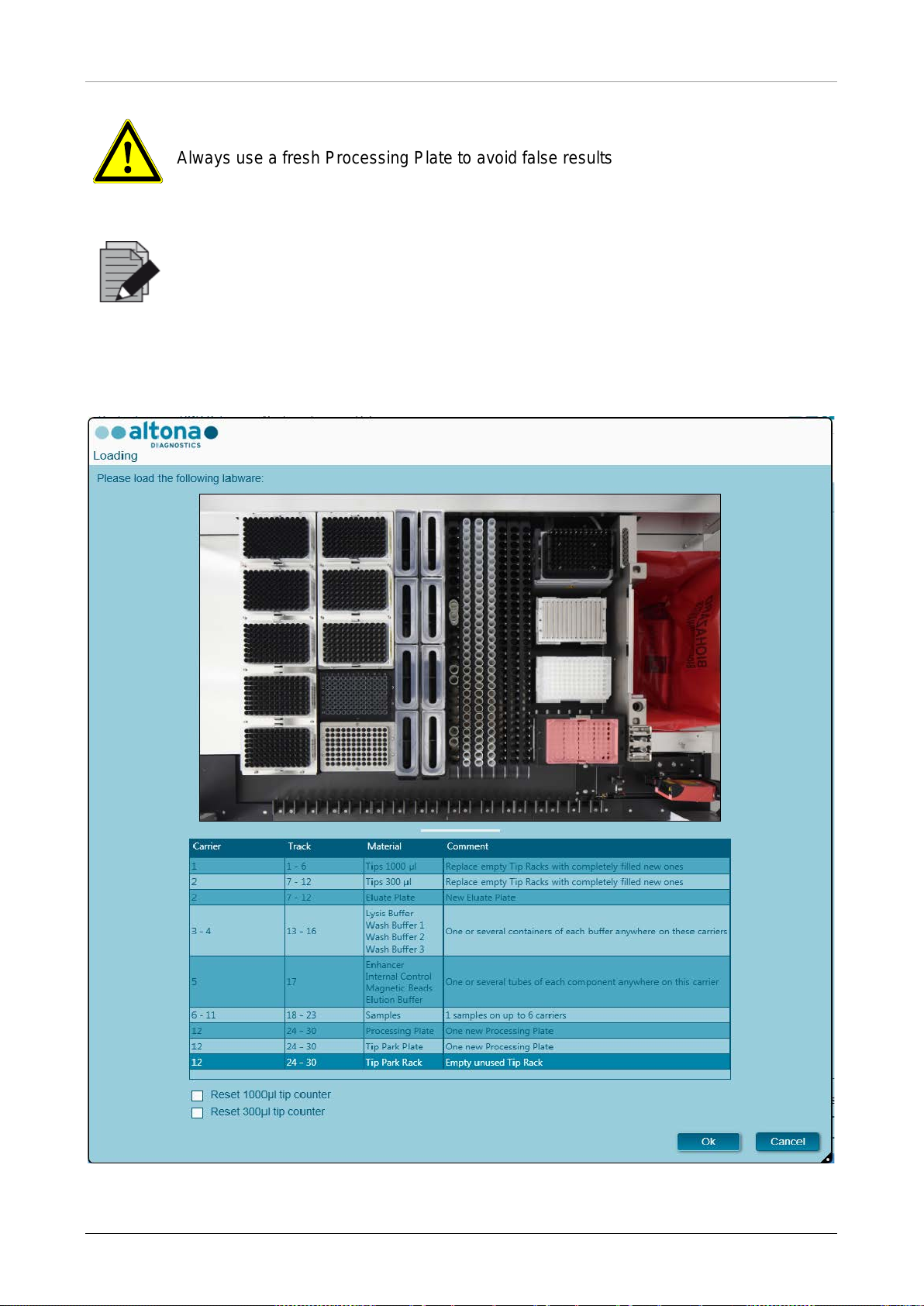
Fig. 19.: Purif i cation Loading Dialog
28 627108_00
Page 35
AltoStar® Automation System AM16 – OPERATOR’S MANUAL IVD
Do not move or remove individual tips on a Tip Rack as this will interfere with the
the tip counters for the 1000 µl tips and the 300 µl tips can be reset by checking
all
tip positions on carriers 1 and 2 have to be filled completely. The user has to
Reset Tip
When handling patient samples, wear personal protective apparel, including
disposable gloves, to avoid infection. Wash hands thoroughly after removing
ers and decrease the risk of contamination,
Always use a fresh Deep Well Plate in the Tip Park Module to avoid false
Rack in the Tip Park Module which hasn´t been used
The Loading dialog consists of a visual representation of the instrument deck at the top half and a
table specifying all items to be loaded in the bottom half.
Begin by selecting the lines of the table by clicking them one by one, starting at the top.
The position of the material currently selected in the Loading dialog table is further visualized:
• In red in the image at the top.
• By flashing Loading Lights of the instrument above the tracks where the carrier holding the
respective items must be placed.
Follow the instructions in the Comment column carefully.
To load the carriers, insert them into the tracks between the front and rear slide blocks of the
Loading Tray until they touch the stop hooks on the far side of the Loading Tray. Do not push the
carriers past the stop hooks.
ATTENTION
tip counter of the software. In case the tip positions were modified by the user,
the respective check boxes at the bottom of the Loading Dialog. In this case,
confirm that all Tip Racks are completely filled in the subsequent
Counters dialog.
ATTENTION
gloves, and dispose of gloves as biohazardous waste.
ATTENTION
To prevent damage to the carri
extend the safety guards whenever carriers are loaded on the Loading Tray.
ATTENTION
results.
ATTENTION
Always use an empty Tip
in that position before.
627108_00 29
Page 36
AltoStar® Automation System AM16 – OPERATOR’S MANUAL IVD
Do not exchange positions of any loaded material after it has been drawn into
the instrument by the Autoload, as this could result in incorrect test results,
and the Tip Waste Container are in the cor rect
NOTE
aborting the run and damage to the instrument.
NOTE
Check that the Tip Eject Sheet
position and a new Waste Bag is placed in the container.
After all carriers are loaded on the correct tracks of the Loading Tray, click OK in the loading dialog.
By clicking Cancel, the run will be cancelled, but it can be started again.
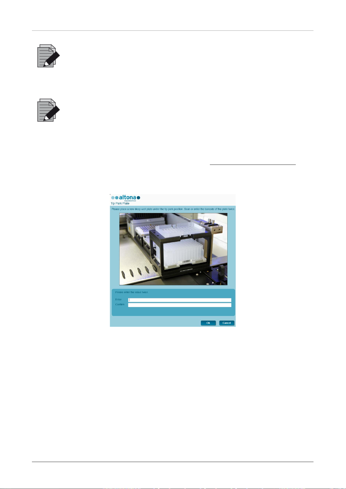
After clicking OK, the Tip Pa rk Plate dialog is displayed (see Fig. 20.: Tip Park Plate Dialog
plate barcode has to be scanned in duplicate with the handheld barcode scanner or entered by
keyboard to ensure that the plate has not been used in prior runs. Click OK to confirm the input.
). The
Fig. 20.: Tip Park Plate Dialog
The instrument loads the carriers with the Autoload and automatically verifies:
• Correct identity and localization of the loaded carriers
• Correct identity of the items loaded on the carriers
• Positions of the items loaded on the carriers
• Lot conformity of the Lysis Buffer, the Wash Buffers, the Magnetic Beads, the Enhancer
and the Elution Buffer
• Non-expiry of all loaded reagents
• Presence of sufficient reagent volumes
• Singularity of sample barcodes
30 627108_00
Page 37
AltoStar® Automation System AM16 – OPERATOR’S MANUAL IVD
ll carriers or the instrument door during a run as this may abort
dialog is closed will void the run
prior to the sample transfer.
Short samples will be error flagged during the sample transfer step and will not
• Correct positioning of the items loaded manually on the Heater Shaker Carrier
• Correct positioning of the Tip Eject Sheet
If any of these checks fail, the user is prompted with a message dialog specifying the problem at
hand and instructions to correct the issue accordingly. For further information regarding error
handling see the AltoStar
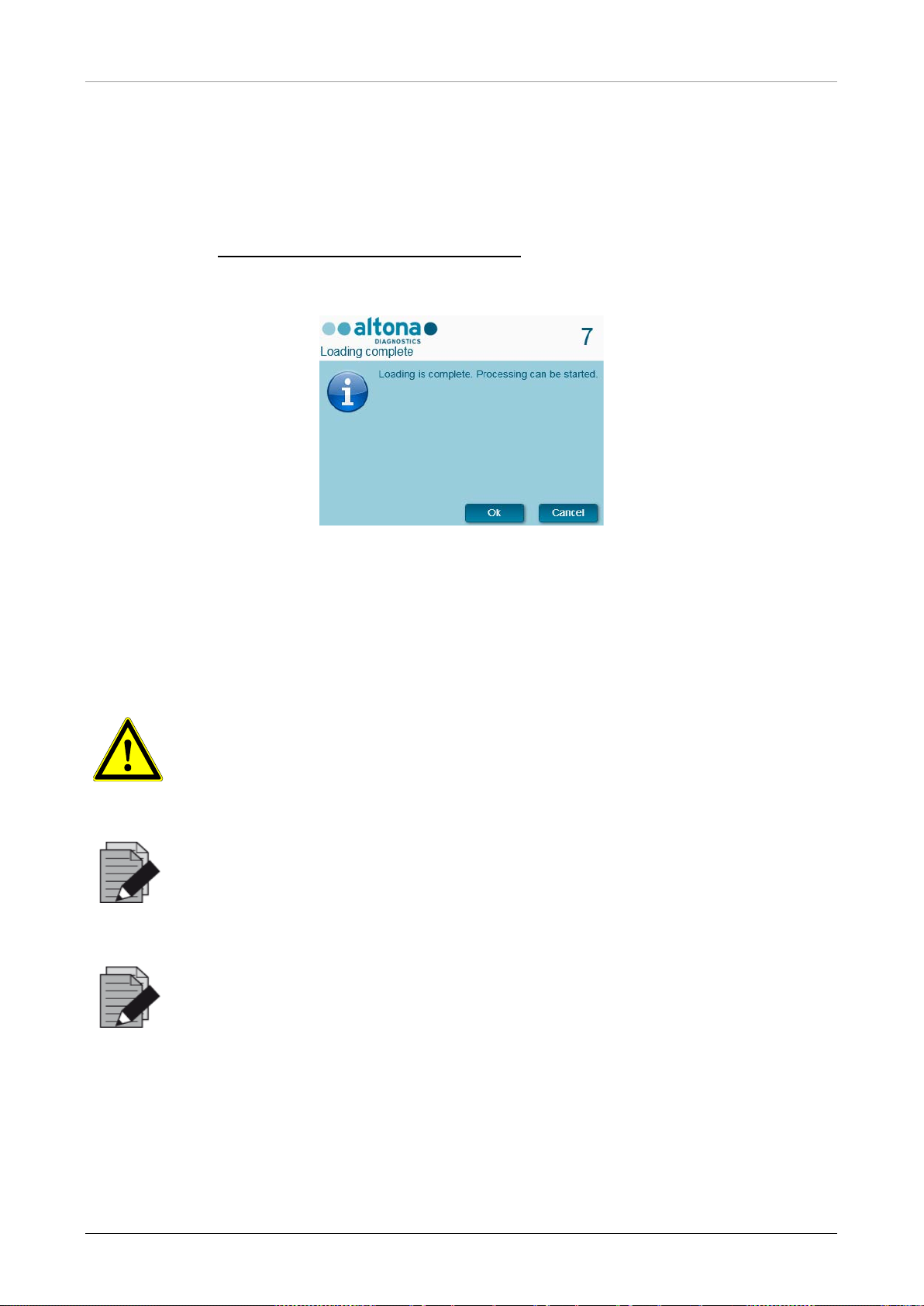
When all checks have passed, the Loading Complete dialog is displayed. Confirm the Loading
Complete message by clicking OK or wait 10 seconds.
®
Connect Software Manual IVD.
Fig. 21.: Loading Complete Dialog
The system now performs the purification automatically, no further user interaction is required until
the run has finished. If you click Cancel, t he run will abort. When canceling, t he ru n up to t his t ime
it can be started again later.
ATTENTION
Do not push or pu
the run.
NOTE
Aborting the run after the Loading Complete
definition, preventing a restart.
NOTE
The sample volume is not checked by the system
be processed further.
627108_00 31
Page 38
AltoStar® Automation System AM16 – OPERATOR’S MANUAL IVD
be restarted. All data and used reagents will be lost
3.4.6 During the Purification Run
The purification run will be conducted without user intervention after starting. After the sample
transfer into the Processing Plate, the sample carrier(s) can be unloaded at any time. The Unload
samples button in the tool bar will be active and can be clicked. The sample carrier(s) will be
unloaded from the deck and the samples tubes can be removed. The run will not be interrupted.
Fig. 22.: Unload Samples Button
3.4.7 Forced Abort
The run can be aborted by clicking the Abort run button in the tool bar and confirming to abort the
run in the subsequent Abort Run dialog.
ATTENTION
Once aborted, a run cannot
and the run will be error flagged.
3.4.8 End of the Purification Run
At the end of the run, the Run Finished dialog is displayed. Make s ure the Loading Tray i s empty
and confirm the Run Finished dialog by clicking OK. The instrument will unload the carriers. Make
sure not to stand in the way of the unloading carriers.
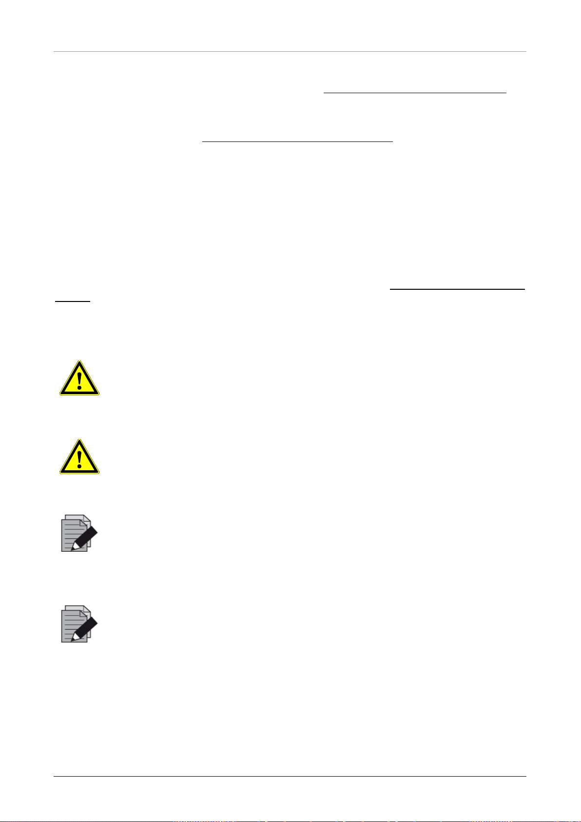
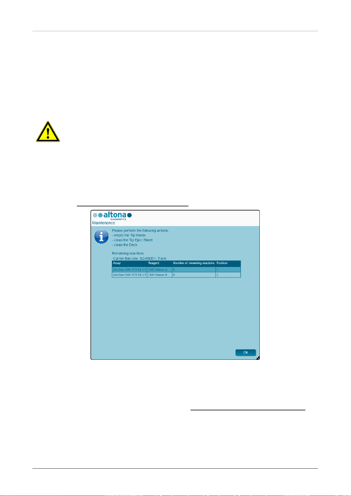
After unloading, the Maintenance dialog is displayed (see
Finished Run). Follow the instructions of the Maintenance dialog.
Fig. 23.: Maintenance Dialog After
Fig. 23.: Maintenance Dialog After Finished Run
32 627108_00
Page 39
AltoStar® Automation System AM16 – OPERATOR’S MANUAL IVD
free gloves when handling kit
are from t he same
during loading and instructs the user
reagents are not expired. The
uring loading and
Use the table of the dialog to identify reagents that can be used again in subsequent runs. Dispose
of all reagents not listed in the table. Refer to the AltoStar
®
Purification Kit 1.5 Manual for
information regarding sealing, storage and disposal.
Confirm the Maintenance dialog by clicking Ok.
®
For further information see the AltoStar
Connect Software Manual IVD.
3.5 PCR Setup
The PCR setup process is the same irrespective of the purification workflow chosen for the
samples (AltoStar
3.5.1 Preparing Reagents for a PCR Setup Run
All reagents should be thawed completely, mixed (by pipetting or gentle vortexing) and centrifuged
briefly before use. For detailed information, refer to the respective altona Diagnostics PCR Kit
Manual.
All reagent tubes are barcoded for automated identification, localization and verification of lot
conformity and non-expiry by the AltoStar
®
workflow, Sample Transfer workflow or External Purification workflow).
®
system.
ATTENTION
Always wear protective disposable powdercomponents.
ATTENTION
Do not manually transfer any liquids.
NOTE
Ensure that all components of the altona Diagnostics PCR Kit
lot. The software verifies lot conformity
accordingly.
NOTE
Ensure that your altona Diagnostics PCR Kit
software verifies use within the shelf life of the reagents d
instructs the user accordingly.
627108_00 33
Page 40
AltoStar® Automation System AM16 – OPERATOR’S MANUAL IVD
for a given run can be
Start ing a P CR Se tup
he required components during the
The subsequent PCR run must be started within 30 minutes after the completion
NOTE
Required components of the altona Diagnostics PCR Kit
previewed in the AltoStar® Connect SW (see Chapter 3.4.2
Run). This allows for preparation of t
preceding purification run.
NOTE
of the PCR Setup.
Before starting the PCR Setup run, ensure that the material required f or the subsequent PCR run
will be available and ready to use at the end of the PCR Setup run to avoid prolonged storage of
the completed PCR plate:
• PCR Plate Sealing Foil
• Heat Sealer
• CFX96™ DW Cycler
3.5.2 Starting a PCR Setup Run
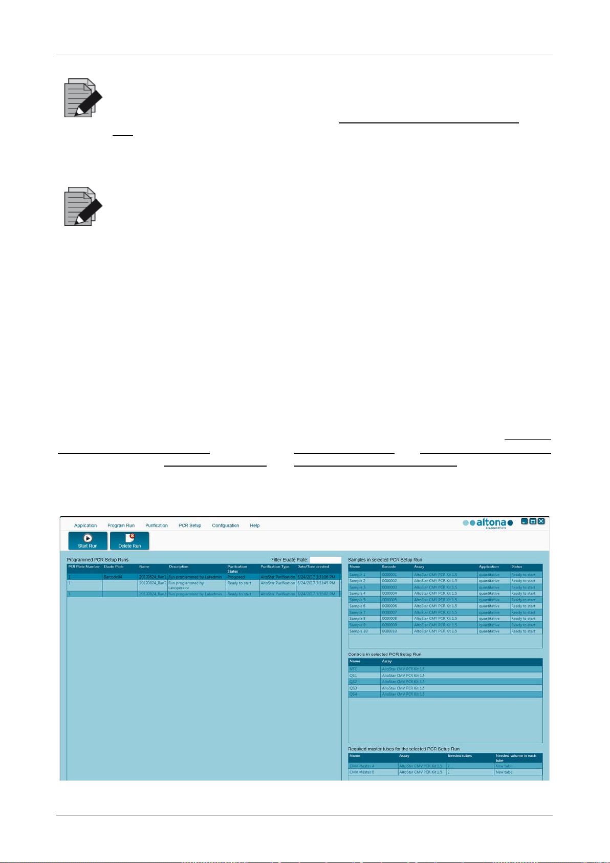
The PCR Setup for an AltoStar® PCR Kit can be started as soon as the associated purification run
is complete. How to program a run and start a purification run is explained in the AltoStar
Connect Software Manual IVD in the Chapters Programming a Run and Starting a Purification Run
as well as Chapters Programming a Run and Starting a Sample Transfer Run. To s tart th e PCR
setup run, go back to the Start Window of the AltoStar® Connect SW and select Start PCR Setup
or select PCR
→ Start PCR Setup in the menu bar. Your PCR setup run definitions are displayed
in the Programmed PCR Setup Runs table on the left side of the screen.
®
Fig. 24.: St art Screen for PCR Setup
34 627108_00
Page 41
AltoStar® Automation System AM16 – OPERATOR’S MANUAL IVD
definitions can be accessed any time after programming,
the required
reagents for an upcoming PCR setup run can be previewed and prepared in
button is inactive, the purification leading up to the currently
selected PCR setup run definition has not been completed. Refer to column
• Select the PCR setup run definition to be started in the Programmed PCR Setup Runs
table.
• The samples included in the selected run definition are displayed in the Samples in
selected PCR Setup Run table on the top right side of the screen.
• The controls included in the selected run definition are displayed in the Controls in
selected PCR Setup Run table on the middle right side of the screen.
• The number of master reagent tubes required for the selected run definition is displayed in
the Required master tubes for the selected PCR Setup Run table on the bottom right
side of the screen.
• Click the St art Run button in the tool bar to start the selected PCR setup run definition.
• Click Delete Run to completely delete the selected programmed PCR Setup run.
For further information see the AltoStar
NOTE
The PCR setup run
including during an ongoing purification or PCR setup run. This way,
®
Connect Software Manual IVD.
advance so that a PCR setup run can be started right after the end of the ongoing
run.
NOTE
If the Start Run
Purification Status in the table Programmed PCR setup Runs for information.
3.5.3 Instrument Loading for the PCR Setup Run
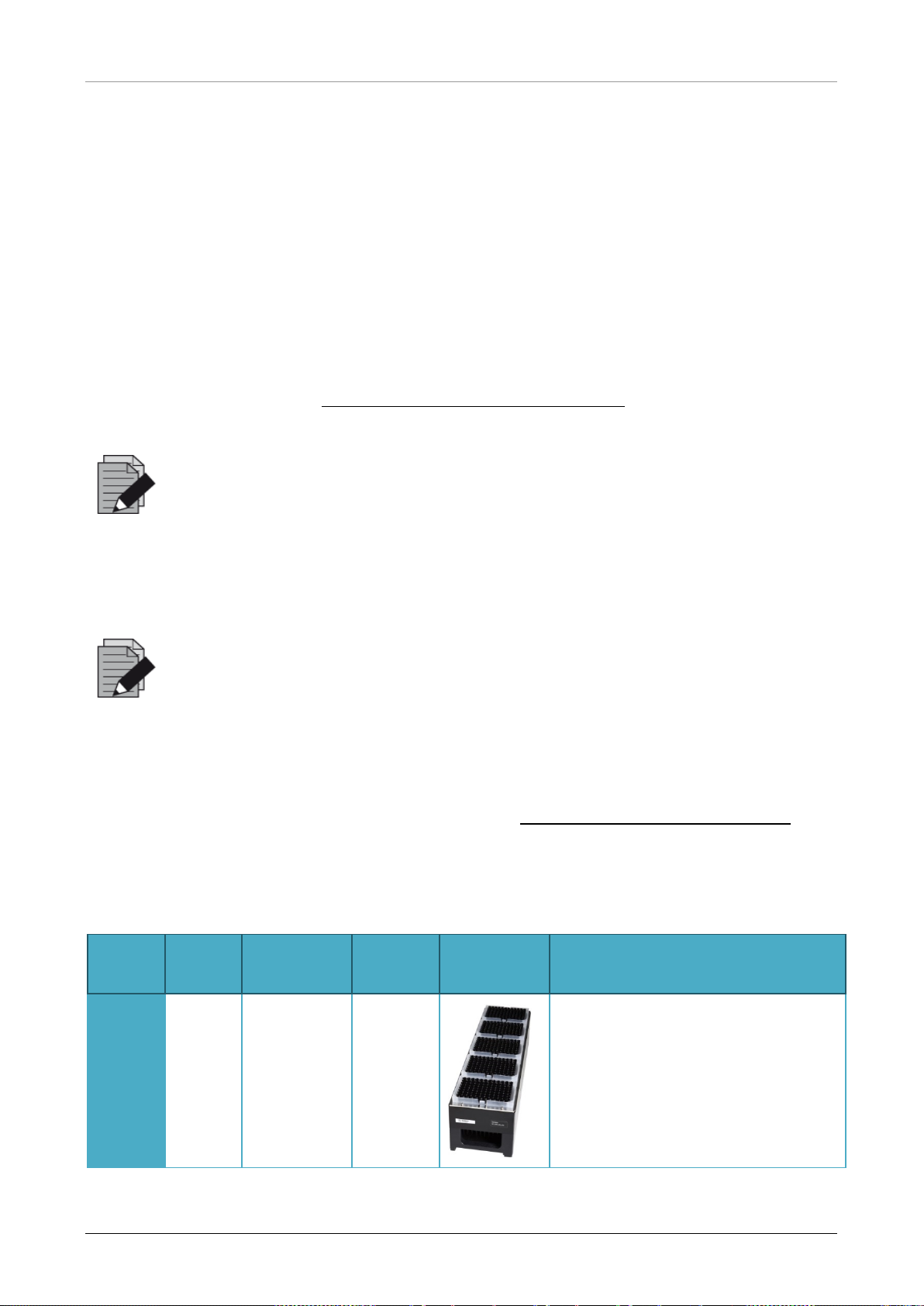
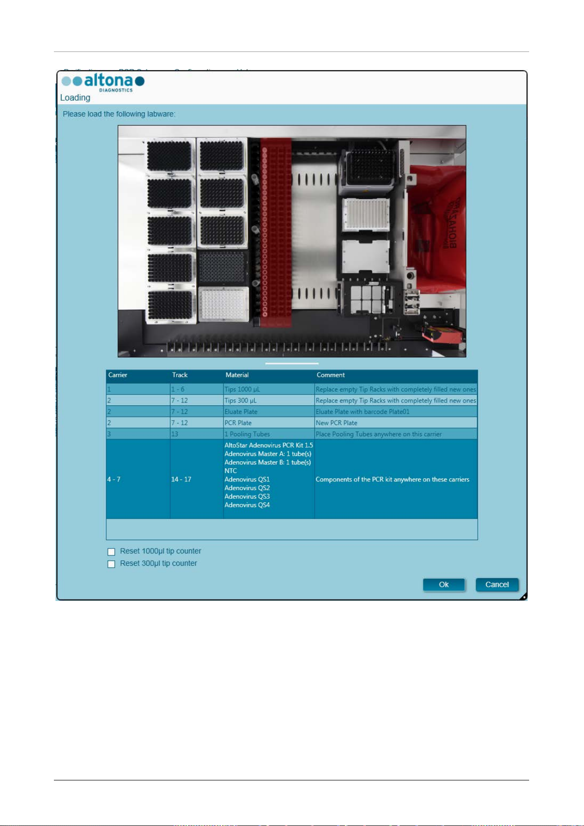
At the start of a run the Loading dialog is displayed (see Fig. 25.: PCR Setup Loading Dialog). The
material, reagents and samples have to be loaded onto suitable carriers, before these carriers can
then be loaded onto the respective tracks on the Loading Tray of the instrument:
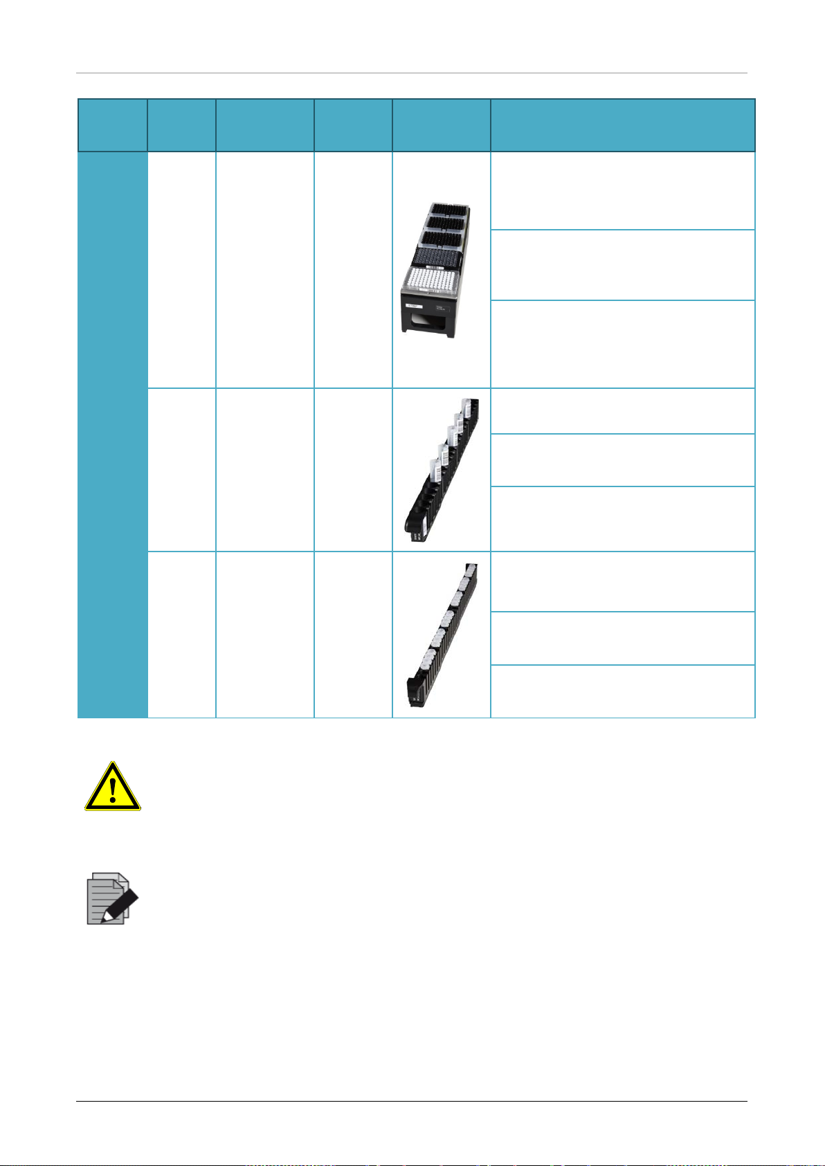
Table 4: Carrier Description: PCR Setup Run
Carrier
No.
Track Material
Carrier
Name
Image Notes
Only exchange completely empty Tip
Racks for completely full ones. Do
not handle individual tips.
1
1 - 6
5 racks of
1000 µl tips
Tip
Carrier
627108_00 35
Page 42
AltoStar® Automation System AM16 – OPERATOR’S MANUAL IVD
before loading the carriers onto the Loading Tray.
Carrier
No.
2
3
Track Material
3 racks of
300 µl tips
7 - 12
1 Elution
Plate
1 PCR
Plate
One
13
Pooling
Tube per
assay
Carrier
Name
Tip and
Plate
Carrier
Tube
Carrier
24
Image Notes
Only exchange completely empty Tip
Racks for completely full ones. Do
not handle individual tips.
Always place plates with well A1 to
the left of the respective plate
position.
The PCR plate is placed at the front
most position, the elution plate at the
second front most position of this
carrier.
One carrier can be loaded.
The position of the individual tubes
on the carriers is arbitrary.
Gently push the tubes down all the
way to the bottom of the carrier.
4 - 7
The position of the individual tubes
on the carrier is arbitrary.
Ensure all tube barcodes are visible
through the carrier windows.
Gently push the tubes down all the
way to the bottom of the carrier.
14 - 17
Master
tubes and
standard/co
ntrol tubes
of the
assays
Reagent
Tube
Carrier
32
ATTENTION
Remove the lids of all tubes
Dispose of all lids. To close tubes after the run use new lids.
NOTE
Before loading carriers on the Loading Tray:
• Ensure that no carriers are loaded on the deck inside the instrument.
• Ensure that the barcode on each carrier is toward the rear facing right (toward
the barcode reader on the Autoload).
36 627108_00
Page 43
AltoStar® Automation System AM16 – OPERATOR’S MANUAL IVD
Fig. 25.: PCR Setup Loading Dialog
The Loading dialog consists of a visual representation of the instrument deck at the top half and a
table specifying all items to be loaded in the bottom half.
Begin by selecting the lines of the table by clicking them one by one, starting at the top.
The position of the material currently selected in the Loading dialog table is further visualized:
• In red in the image at the top
• By flashing Loading Lights of the instrument above the tracks where the carrier holding the
respective items must be placed.
627108_00 37
Page 44
AltoStar® Automation System AM16 – OPERATOR’S MANUAL IVD
free gloves when handling kit
Do not move or remove individual tips on a Tip Rack as this will interfere with the
be reset by checking
tip positions on carriers 1 and 2 have to be filled completely. The user has to
Do not exchange positions of any loaded material after it has been drawn into the
and the Tip Waste Container are in the correct
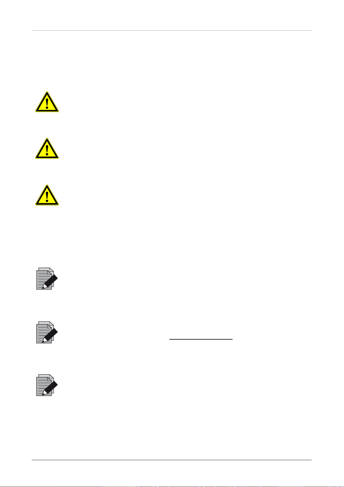
Follow the instructions in the Comment column carefully.
To load the carriers, insert them into the tracks between the front and rear slide blocks of the
Loading Tray until they touch the stop hooks on the far side of the Loading Tray. Do not push the
carriers past the stop hooks.
ATTENTION
Always wear protective disposable powdercomponents.
ATTENTION
To prevent damage to the carriers and decrease the risk of contamination, extend
the safety guards whenever carriers are loaded on the Loading Tray.
ATTENTION
tip counter of the software. In case the tip positions were modified by the user,
the tip counters for the 1000 µl tips and the 300 µl tips can
the respective check boxes at the bottom of the Loading Dialog. In t his case, all
confirm that all Tip Racks are completely filled in the subsequent Reset Tip
Counters dialog.
NOTE
instrument by the Autoload, as this could result in incorrect test results, aborting
the run and damage to the instrument.
NOTE
®
Use only material as described in the AltoStar
PCR Manual.
NOTE
Check that the Tip Eject Sheet
position and a new Waste Bag is placed in the container.
After all carriers are loaded on the correct tracks of the Loading Tray, click OK in the loading dialog.
By clicking Cancel, the run will be cancelled, but it can be started again.
The instrument loads the carriers with the Autoload and automatically verifies:
38 627108_00
Page 45
AltoStar® Automation System AM16 – OPERATOR’S MANUAL IVD
Do not push or pull carriers or the instrument door during a purification run as this
dialog is confirmed will void the run
The volumes of the loaded reagents are not checked during loading. Make sure
reagent tubes. The tubes containing the controls and
quantification standards contain sufficient volumes for four runs. Do not use the
• Correct identity and localization of the loaded carriers
• Correct identity of the items loaded on the carriers
• Positions of the items loaded on the carriers
• Lot conformity of the reagents of the individual kits
• Non-expiry of all loaded reagents
• Correct positioning of the Tip Eject Sheet
If any of these checks fail, the user is prompted with a message dialog specifying the problem at
hand and instructions to correct the issue accordingly.
®
For further information regarding error handling, see the AltoStar
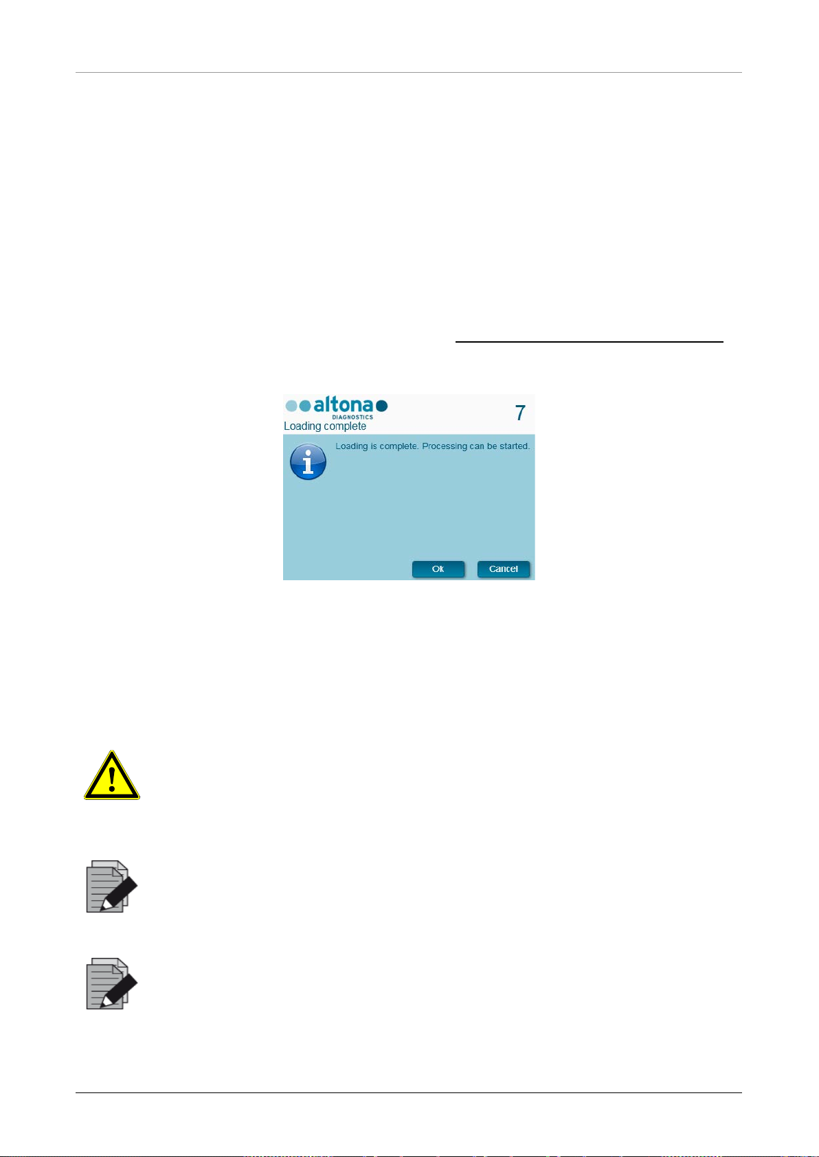
When all checks have passed, the Loading Complete dialog is displayed. Confirm the Loading
Complete message by clicking OK or wait 10 seconds.
Connect Software Manual IVD.
Fig. 26.: Loading Complete Dialog
The system now performs the PCR setup automatically, no further user interaction is requi red u ntil
the run has finished. If you click Cancel, the run will abort. When canceling the run up to this time,
it can be started again later.
ATTENTION
may abort the run.
NOTE
Aborting the run after the Loading Complete
definition, preventing a restart.
NOTE
to only load unused Master
controls and quantification standard tubes for more than four runs.
627108_00 39
Page 46
AltoStar® Automation System AM16 – OPERATOR’S MANUAL IVD
All data and used reagents will be lost
3.5.4 During the PCR Setup Run
The PCR setup run will be conducted without user intervention after starting.
3.5.5 Forced Abort
The run can be aborted by clicking the Abort run button in the tool bar and confirming to abort the
run in the subsequent Abort Run dialog.
ATTENTION
Once aborted, a run cannot be restarted.
and the run will be error flagged.
3.5.6 End of the PCR Setup Run
At the end of the run, the Run Finished dialog is displayed. Make s ure the Loading Tray i s empty
and confirm the Run Finished dialog b y c lic king OK. The instrument will unload the carriers. Make
sure not to stand in the way of the unloading carriers. After unloading the Maintenance dialog is
displayed (see Fig. 27.: Maintenance After Run Dialog
).
Fig. 27.: Maintenance After Run Dialog
Confirm the Maintenance dialog by clicking Ok.
®
For further information regarding maintenance see the AltoStar
Connect Software Manual IVD.
40 627108_00
Page 47

AltoStar® Automation System AM16 – OPERATOR’S MANUAL IVD
If any parts of the instrument, carriers, or racks have become contaminated, the
manufacturer’s instructions. Do not use disinfecting materials which contain
4 Maintenance
Periodic maintenance routines need to be run in order to ensure safe and reliable operation of your
AltoStar
For IVD use, the maintenance routines are mandatory and are enforced by the software. It is not
possible to start runs when maintenance or verification is overdue.
®
AM16 instrument and the accessories.
4.1 Maintenance Intervals
• Daily Maintenance: Has to be executed every 24h. Recommended after AltoStar® AM16
start-up.
• Weekly Maintenance: Has to be executed every 7 days. Recommended at the end of the
week before AltoStar
have become contaminated, the weekly maintenance procedure must be performed.
• Verification: Has to be executed every 200 days. Preventive maintenance and verification
is carried out by a Hamilton trained field service engineer.
NOTE
weekly maintenance procedure must be performed.
®
AM16 shut-down. If any parts of the instrument, carriers, or racks
4.2 Materials Required
• Disposable latex gloves
• Protective glasses
• Lab coat
• Paper towels
• Lint-free cloths or Q-tips
• Ethanol (70%)
• De-ionized water
• MICROLAB Disinfectant Spray
• MICROLAB Detergent and Disinfectant
ATTENTION
Use cleaning, disinfecting and decontaminating fluid in accordance with the
hypoclorite (Javel water, Chlorox) or bleaching fluids.
Prepare disinfectant fluids according to their labeling.
627108_00 41
Page 48
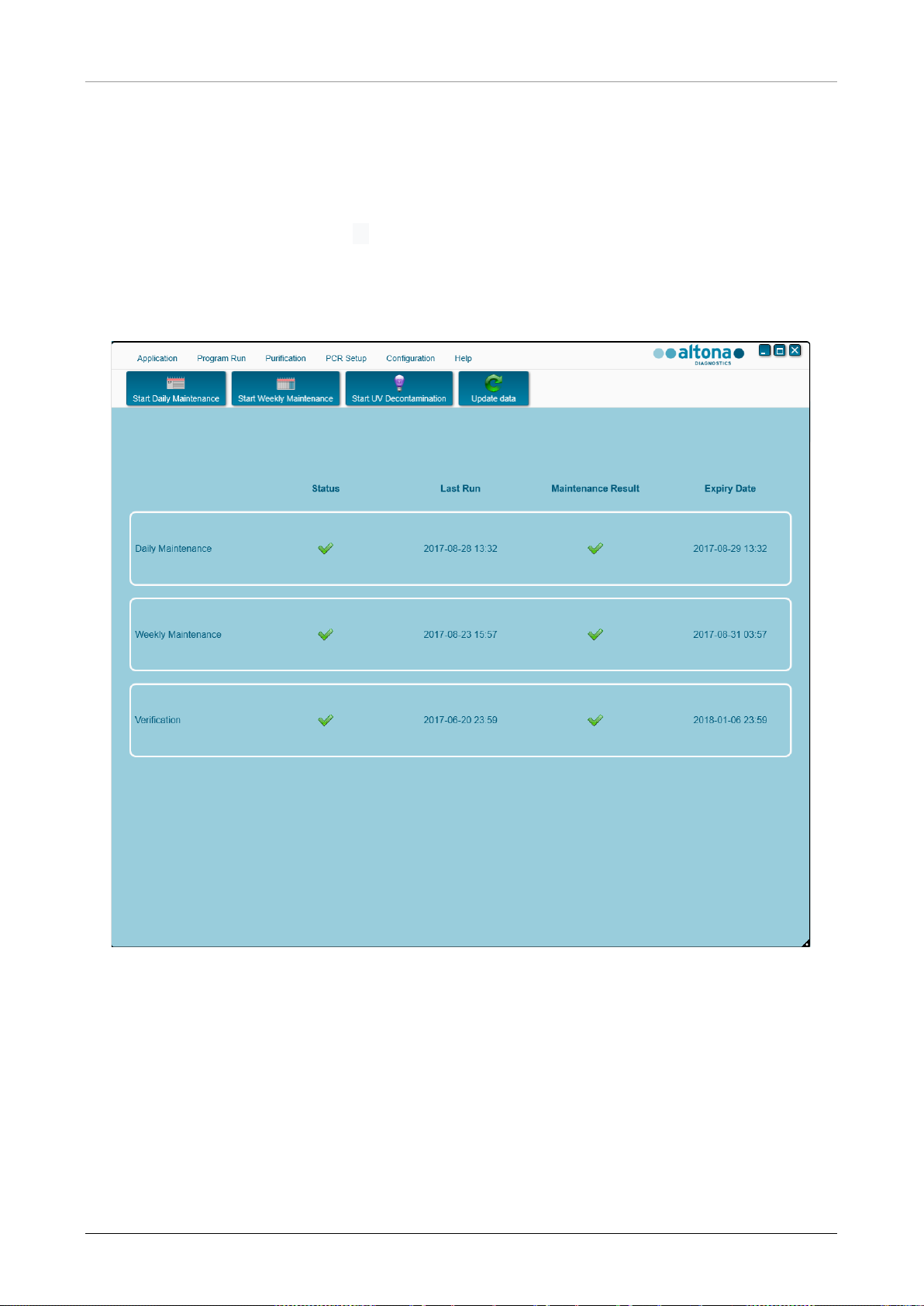
AltoStar® Automation System AM16 – OPERATOR’S MANUAL IVD
4.3 Maintenance Procedures
Access the Maintenance screen by click ing Application → Instrument Maintenance in the menu
bar.
A valid status of the Daily Maintenance, Weekly Maintenance and the semi-annual Verification is
depicted by a green check mark ✔ in the column Status. If a red X mark is displayed in this
column, the respective maintenance procedure has to be performed by clicking the corresponding
button in the tool bar. Follow the on screen instructions to complete the maintenance procedure.
By clicking Update data, the maintenance data which are saved on the instrument will be newly
read out and will be shown in the Maintenance Dialog.
Fig. 28.: Maintenance Screen
42 627108_00
Page 49
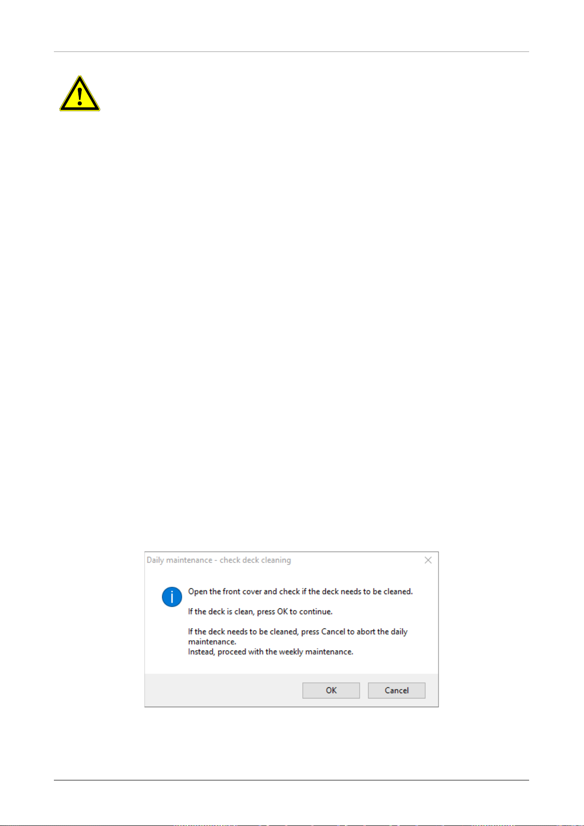
AltoStar® Automation System AM16 – OPERATOR’S MANUAL IVD
flames or devices which
could create sparks. Do not use hot air blowers to dry the instrument. The
waste. In
ATTENTION
Always wear disposable gloves during maintenance.
Do not clean the instrument in the vicinity of open
liquids used for cleaning are flammable.
This manual provides indications regarding general disposal of
addition, any regulations specific to the country of operation must be taken into
account and observed.
Routine Completion
A maintenance routine is completed once the procedure has been fully executed and the results
are within the specifications.
Aborting Maintenance Procedures
Aborting a maintenance procedure will lead to a ‘failed’ status, and maintenance will need to be
started again.
4.4 Daily Maintenance
The following tasks ar e part of the daily maintenance:
• Checking if the deck is clean
• Emptying the tip waste and liquid waste
• Checking the tightness of the pipetting channel
• Verifying the cLLD function
1. Start the daily maintenance by clicking the Start Daily Maintenance button in the tool bar. The
software will issue on-screen instructions detailing all procedures required to perform the daily
maintenance routine.
2. Once the maintenance procedure has been started, the Pipetting Arm moves to the left side.
The operator now has access to the deck to check if cleaning is needed or not.
Fig. 29.: Daily Maintenance – Check Deck Cleaning Dialog
627108_00 43
Page 50
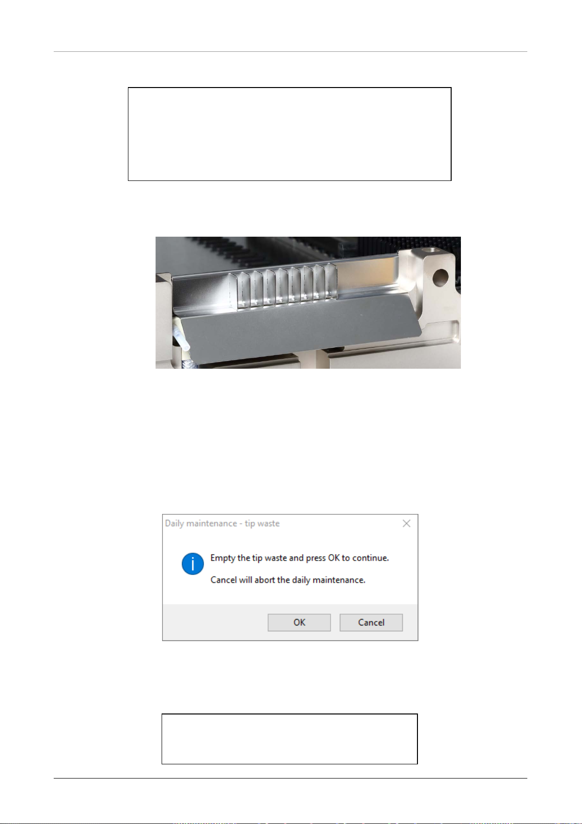
AltoStar® Automation System AM16 – OPERATOR’S MANUAL IVD
Exact wording of content of the dialog displayed in Fig 29:
Open the front cover and check if the deck needs to be cleaned.
If the deck is clean, press OK to continue.
If the deck needs to be cleaned, press Cancel to abort the daily
maintenance.
Instead, proceed with the weekly maintenance.
3. Remove the Tip Eject Sheet of the tip waste station and spray MICROLAB Disinfectant Spray
directly onto the surface and wipe dry. Put the clean Tip Eject Sheet back in place.
Fig. 30.: Tip Eject Sheet
4. If the deck is clean, continue with the daily maintenance.
5. If the deck needs to be cleaned, the daily maintenance can be interrupted. Instead of the daily
maintenance carry out the weekly maintenance.
6. Continuing the daily maintenance procedure will lead the user to the next maintenance task.
The tip waste needs to be emptied. Dispose of it with the rest of the laboratory’s contaminated
waste.
Fig. 31.: Daily Maintenance – Tip Waste
Exact wording of content of the dialog displayed in Fig 31.:
Empty the tip waste and press OK to continue.
Cancel will abort the daily maintenance.
44 627108_00
Page 51
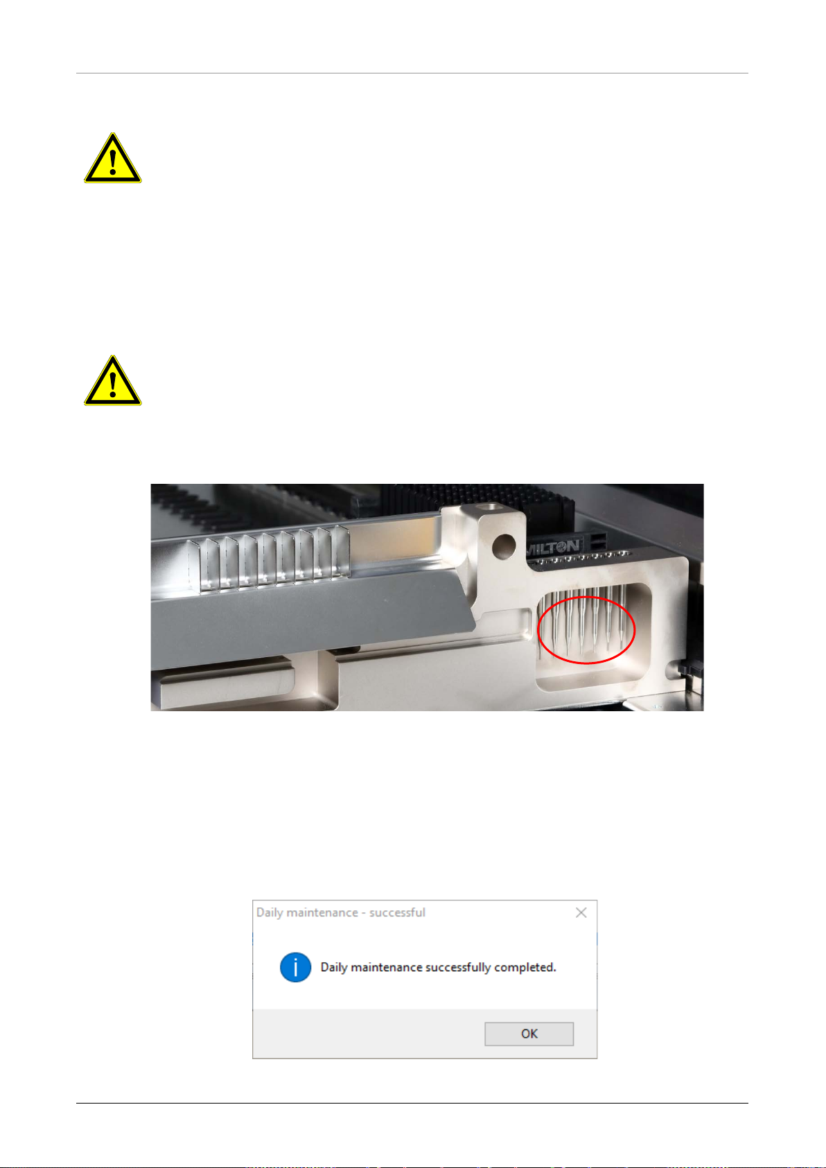
AltoStar® Automation System AM16 – OPERATOR’S MANUAL IVD
and the plastic bag are always to be regarded as contaminated.
ATTENTION
The tip waste is always to be regarded as contaminated.
7. Empty the liquid waste container and check the liquid waste
o Inspect tubing for clogs, kinks and leakage. Tubing must be replaced if damaged.
o Check and clean any liquid spills.
o Check overflow for clogs and clean if required.
ATTENTION
The tip waste, the Tip Eject Sheet, the Liquid Waste Container and Tubings,
8. For the next steps, the maintenance needles are required.
Fig. 32.: Mai ntenance Needles for 1000 μl Pipetting Channels
9. The procedure continues with the tightness check of the pipetting channels. The Pipetting Arm
will travel to the right side to pick up the maintenance needles. Two checks are done with the
pipetting channels, the over-pressure and under-pressure check.
10. For the capacitive liquid level (cLLD) check, the needles are picked up again. One pipetting
channel after the other is checked for proper cLLD function.
Fig. 33.: Daily Maintenance – Successful
627108_00 45
Page 52

AltoStar® Automation System AM16 – OPERATOR’S MANUAL IVD
If any parts of the instrument, carriers or racks have become contaminated, the
Exact wording of content of the dialog displayed in Fig. 33.:
Daily maintenance successfully completed.
11. The daily maintenance process status is saved on the instrument and a report file is created.
NOTE
weekly maintenance procedure must be performed.
46 627108_00
Page 53
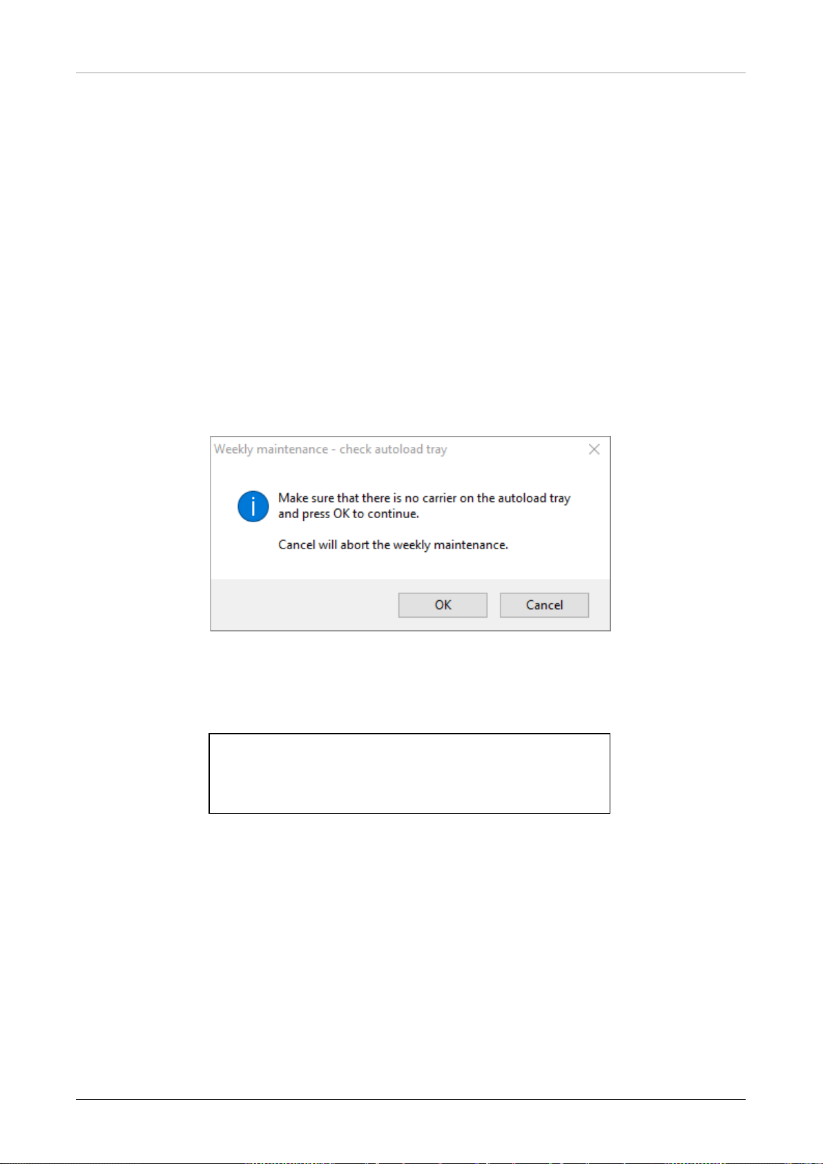
AltoStar® Automation System AM16 – OPERATOR’S MANUAL IVD
Cancel will abort the weekly maintenance.
4.5 Weekly Maintenance
The following tasks are carried out by the weekly maintenance:
• Cleaning the deck and carriers
• Checking the condition of the carriers
• Emptying and cleaning of the tip waste and liquid waste
• Checking the tightness of the pipetting channel
• Verifying the cLLD function
• Cleaning of the pipetting head: stop disk, O-ring, tip eject sleeve
• Cleaning of the covers, Autoload protecting ribbon
1. Start the weekly maintenance by clicking the Start Weekly Maintenance button in the tool bar.
The software will issue on-screen instructions detailing all procedures required to perform the
weekly maintenance routine.
Fig. 34.: Weekly Maintenance – Check Autoload Tray
Exact wording of content of the dialog displayed in Fig. 34.:
Make sure that there is no carrier on the autoload tray
and press OK to continue.
627108_00 47
Page 54
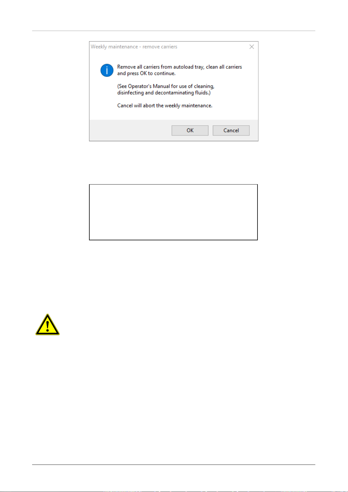
AltoStar® Automation System AM16 – OPERATOR’S MANUAL IVD
Fig. 35.: Weekly Maintenance – Remove Carriers
Exact wording of content of the dialog displayed in Fig. 35.:
Remove all carriers from autoload tray, clean all carriers
and press OK to continue.
(See Operator’s Manual for use of cleaning,
disinfecting and decontaminating fluids.)
Cancel will abort the weekly maintenance.
2. Clean all carriers with the MICROLAB Disinfectant Spray and leave them to dry. If they are
heavily soiled, soak these carriers afterwards in a solution of MICROLAB Detergent and
Disinfectant (see the product data sheet for further information).
3. Examine each carrier for scratches on the barcode and any signs of damage. If damage is
apparent, replace with new carriers.
ATTENTION
Do not spray directly at the Autoload unit or at electrical boards or connectors.
4. Continuing the weekly maintenance program will advise the Autoload to move to the right hand
side of the instrument.
48 627108_00
Page 55
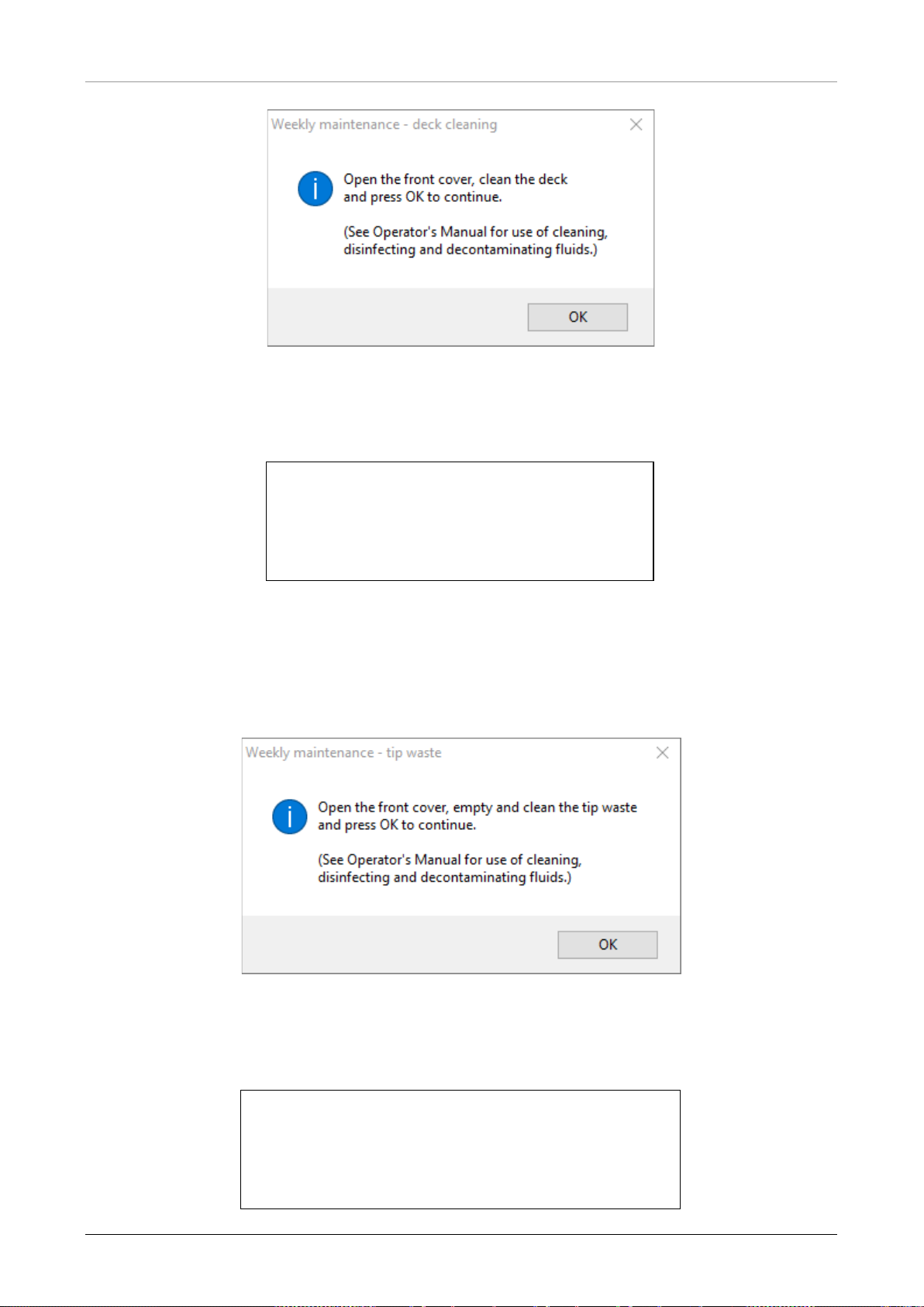
AltoStar® Automation System AM16 – OPERATOR’S MANUAL IVD
Fig. 36.: Weekly Maintenance – Deck Cleaning
Exact wording of content of the dialog displayed in Fig. 36:
Open the front cover, clean the deck
and press OK to continue.
(See Operator’s Manual for use of cleaning,
disinfecting and decontaminating fluids.)
5. Open the front cover and wipe the deck with a cloth saturated with MICROLAB Disinfectant
Spray. The slide blocks in particular must be checked for cleanliness. Close the front cover.
6. The next step of the maintenance procedure will advise the Autoload to move to the left hand
side of the instrument. The tip waste needs to be emptied and cleaned. Dispose of tip waste
with the rest of the laboratory’s contaminated waste.
Fig. 37.: Weekly Maintenance – Tip Waste
Exact wording of content of the dialog displayed in Fig. 37.:
Open the front cover, empty and clean the tip waste
and press OK to continue.
(See Operator’s Manual for use of cleaning,
disinfecting and decontaminating fluids.)
627108_00 49
Page 56
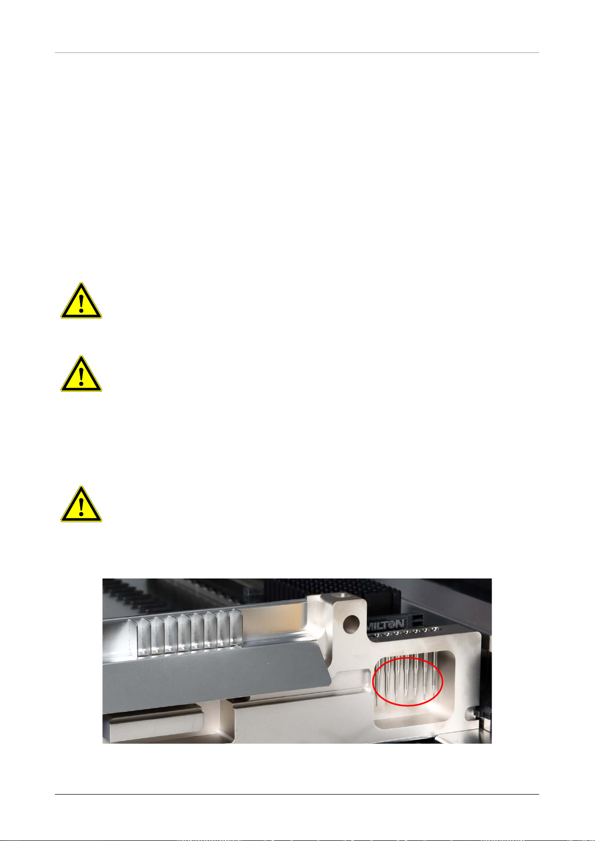
AltoStar® Automation System AM16 – OPERATOR’S MANUAL IVD
The laser scanner window must be completely dry and free from dust and fibers
7. Remove the Tip Eject Sheet of the tip waste station and spray MICROLAB Disinfectant Spray
directly onto the surface and wipe. Remove the plastic bag from the tip waste container and
discard the plastic in the laboratory’s contaminated waste. Place a new plastic bag in the tip
waste container. Put the clean Tip Eject Sheet back in place.
8. Emptying and cleaning of the liquid waste
a. Empty the liquid waste container.
b. Inspect tubing for clogs, kinks and leakage. Tubing must be replaced if damaged.
c. Check and clean any liquid spills.
d. Check overflow for clogs and clean if required.
e. Clean collection tray, tubing and liquid waste container using Ethanol (70%) to flush.
ATTENTION
Do not spray the maintenance needles.
ATTENTION
The tip waste, the Tip Eject Sheet, the Liquid Waste Container and Tubings and
the plastic bag are always to be regarded as contaminated.
9. To prevent unreliable barcode reading, check the laser scanner window of the barcode reader
and clean it with a lint-free cloth or Q-tips lightly soaked in Ethanol (70%).
ATTENTION
before the instrument can be reused.
10. For the next steps, the maintenance needles are required.
Fig. 38.: Mai ntenance Needles 1000 μl Pipetting Channels
50 627108_00
Page 57
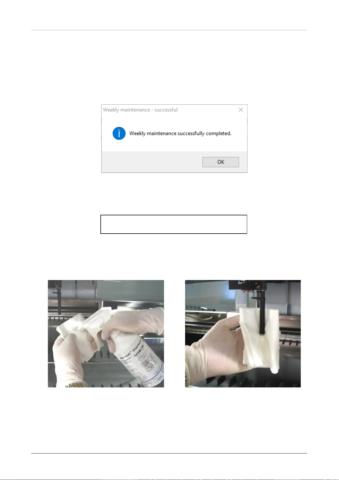
AltoStar® Automation System AM16 – OPERATOR’S MANUAL IVD
11. The procedure continues with the tightness check of the pipetting channels. The Pipetting Arm
will travel to the right hand side to pick up the maintenance needles. Two checks are done with
the pipetting channels, the over-pressure and under-pressure check.
12. For the capacitive liquid level (cLLD) check, the needles are picked-up again. One pipetting
channel after the other is checked for proper cLLD function.
13. The end of the weekly maintenance program is displayed:
Fig. 39.: Weekly Maintenance – Successful
Exact wording of content of the dialog displayed in Fig. 39.:
Weekly maintenance successfully completed.
14. The weekly maintenance process status is saved on the instrument and a report file is created.
15. Clean the tip eject sleeve (outer part of the pipetting heads) with a lint-free cloth soaked in
MICROLAB Disinfectant Spray.
Fig. 40.: Cleaning the Tip Eject Sleeve
627108_00 51
Page 58

AltoStar® Automation System AM16 – OPERATOR’S MANUAL IVD
slide. Never force them as this
may lead to damage. If possible, switch on the instrument as this will result in
hannels have to be moved on the
ATTENTION
Take care that no liquid gets inside the pipetting channel.
Whenever it is necessary to move the pipetting channels on the Pipetting Arm,
move them gently by pushing close to their Ya smoother motion when the pipetting c
Pipetting Arm.
52 627108_00
Page 59
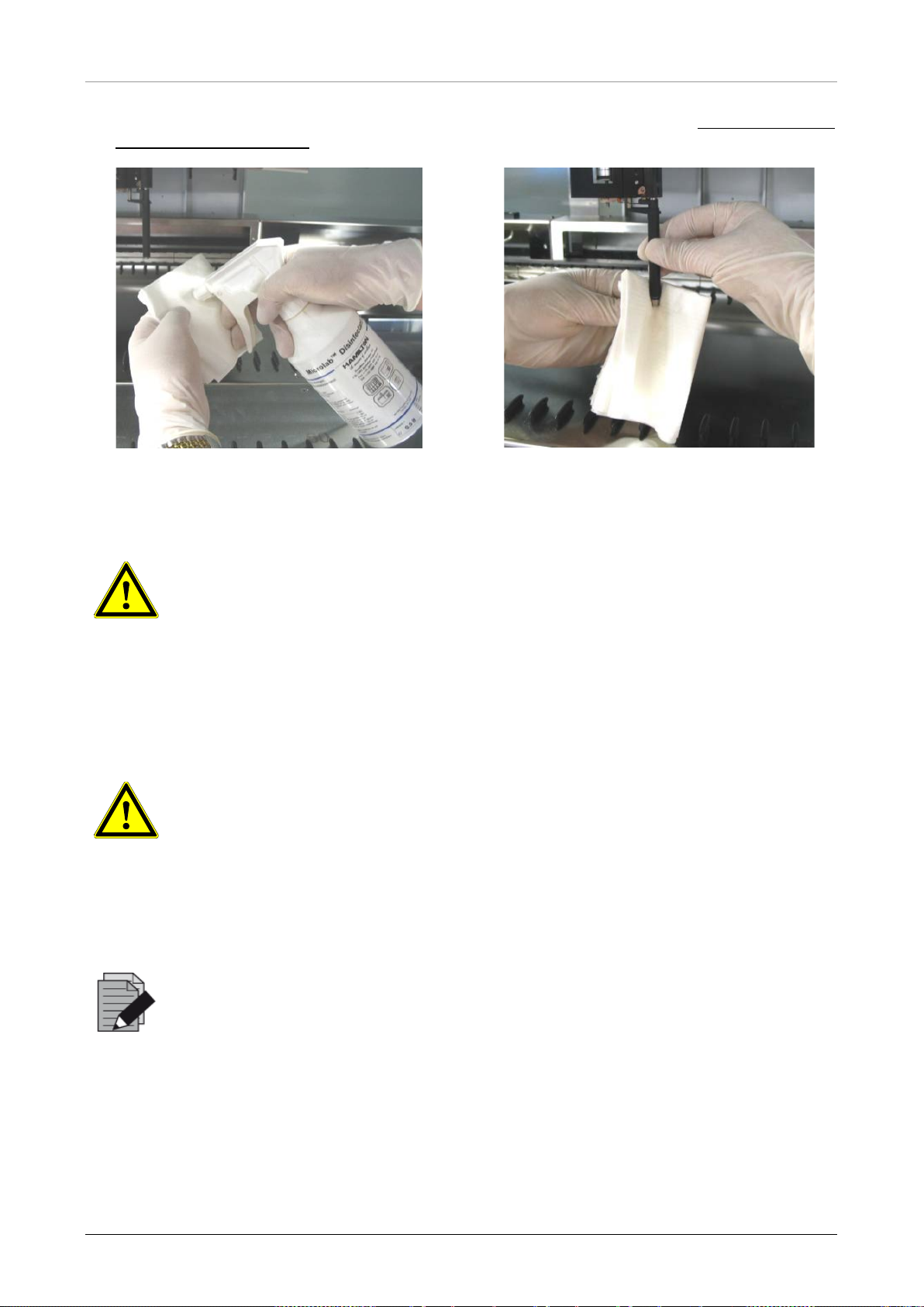
AltoStar® Automation System AM16 – OPERATOR’S MANUAL IVD
16. Clean the stop disk and the O-rings (outer part of the pipetting heads, see Fig. 41.: Cleaning
the Stop Disk and O-Ring) with a lint-free cloth soaked in MICROLAB Disinfectant Spray.
Fig. 41.: Cleani ng the Stop Disk and O-Rings
ATTENTION
Take care that no liquid gets inside the pipetting channel.
17. Spray the front and side cover with MICROLAB Disinfectant Spray and wipe dry.
18. Clean the Autoload protecting ribbon with a cloth soaked in MICROLAB Disinfectant Spray,
and wipe without exerting pressure.
ATTENTION
Do not spray directly at the Autoload unit or at electrical boards or connectors.
19. Clean the Pipetting Arm guide shaft behind the upper front cover with a dry cloth at least once
a month.
NOTE
Carriers must be completely clean and dry before re-using.
4.6 If Maintenance Fails
If an error is encountered during a maintenance procedure, try to resolve the problem and restart
the maintenance procedure. If you cannot resolve the error yourself, contact altona Diagnostics
GmbH.
627108_00 53
Page 60
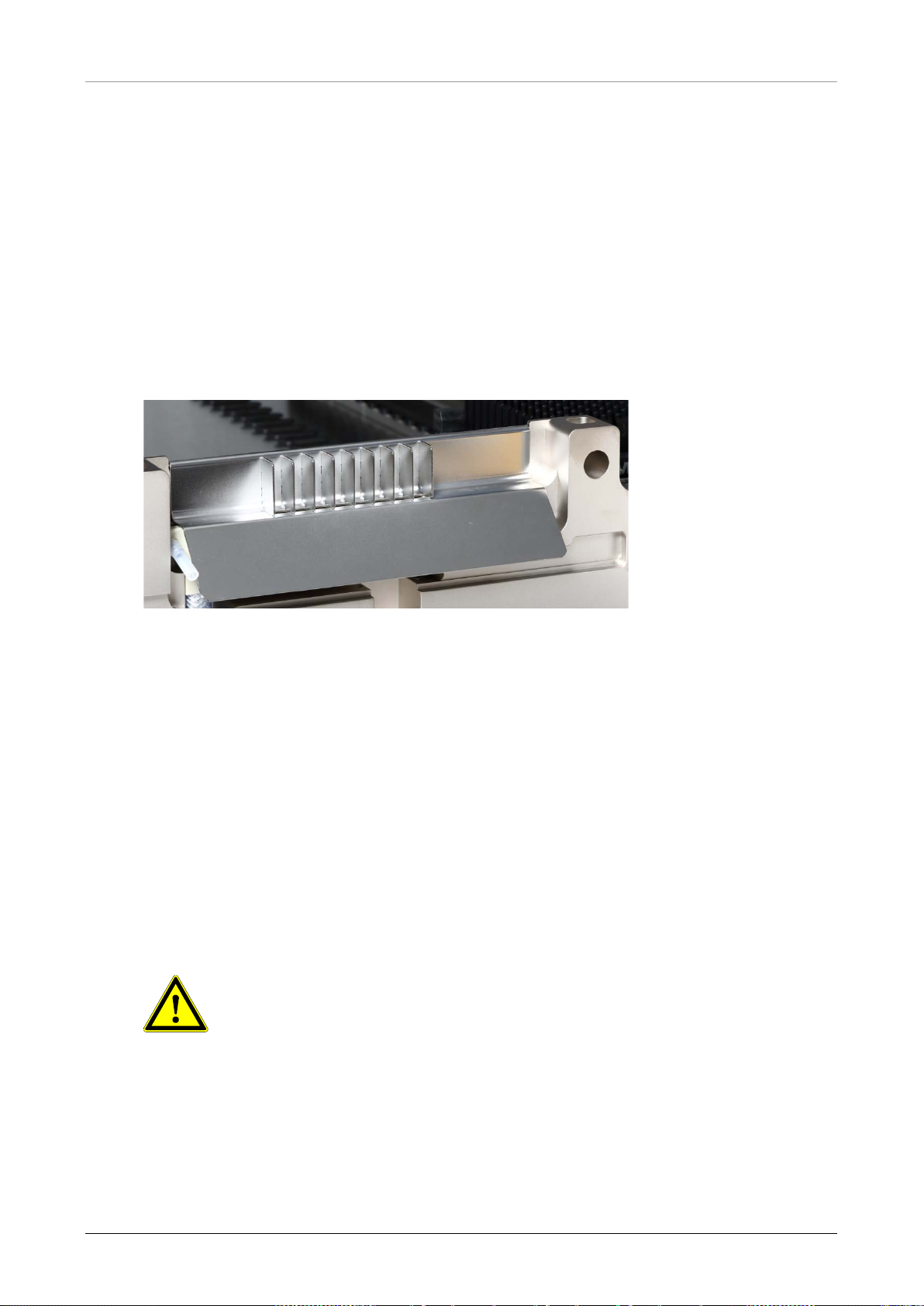
AltoStar® Automation System AM16 – OPERATOR’S MANUAL IVD
Tubings and the plastic bag are always to be regarded as contaminated.
5 AltoStar® AM16 Decontamination
The following is the recommended procedure for decontaminating the AltoStar® AM16 instrument:
1. Spray the front and side cover with MICROLAB Disinfectant Spray.
2. Open the front cover and wipe the deck with a cloth saturated with MICROLAB Disinfectant
Spray.
• The slide blocks in particular must be checked for cleanliness
3. Remove the Tip Eject Sheet of the tip waste station and clean it.
• Spray MICROLAB Disinfectant Spray directly onto the surface of the tip waste station and
wipe.
Fig. 42.: Tip Eject Sheet
4. Discard the plastic bag in the laboratory’s contaminated waste.
5. Put the Tip Eject Sheet in place.
6. Clean the tip eject sleeve (outer part of the pipetting channels) with a lint-free c loth soak ed in
MICROLAB Disinfectant Spray.
7. Clean all carriers with MICROLAB disinfectant spray and let them dry.
• If they are heavily soiled, soak them afterwards in a solution of MICROLAB detergent and
disinfectant (see the product data sheet for further information).
8. Empty the liquid waste container and check the liquid waste
• Check and clean any liquid spills.
ATTENTION
The tip waste, the Tip Eject Sheet the Liquid Waste Container and
9. Emptying and cleaning of the liquid waste
• Empty the liquid waste container.
• Clean collection tray, tubing and liquid waste container using Ethanol (70%) to flush.
54 627108_00
Page 61
AltoStar® Automation System AM16 – OPERATOR’S MANUAL IVD
decontamination with appropriate protection especially the
Microlab STAR Line UV Kit,
Microlab STAR Line UV Kit,
to completely close the instrument before
6 AltoStar® AM16 UV Decontamination
A UV-Lamp assembly (Microlab STAR Line UV Kit, Ham ilton) has been installed in order to offer
the user the option of UV decontamination of the AltoStar
®
AM16. The required duration and
frequency is dependent on the used substances and on the frequency the system is used. The
user is responsible for setting the appropriate duration and frequency.
Carriers and other accessories are not meant to be decontaminated by the UV Kit. The UV light
cannot reach all surfaces of complex structures. Remove the carriers for UV decontamination.
ATTENTION
Only use the UV
UV front cover of the system.
NOTE
Read the UV Kit Manual before using the UV Kit! (
Hamilton)
6.1 Operating the UV Kit
This chapter is dedicated to the user and focuses on a safe operation of the UV Kit based on the
standard UV decontamination method.
NOTE
Read the UV Kit Manual before using the UV Kit! (
Hamilton)
ATTENTION
Wear suitable face shield, gloves and protective clothing. Make sure that the UV
cover is placed in the correct position
switching on the UV light.
627108_00 55
Page 62
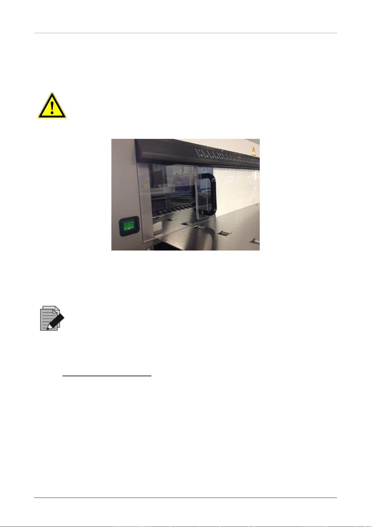
AltoStar® Automation System AM16 – OPERATOR’S MANUAL IVD
Do not use the UV front cover during a different method run, as carriers could be
The UV decontamination method enables automated UV irradiation. Therefore,
the user can set the duration for how long the irradiation shall take place and a
6.1.1 Mounting the UV Front Cover
The UV front cover shall be used to close the instrument completely whenever the UV light is
switched on. Place the UV front cover as indicated in the picture below.
ATTENTION
unloaded automatically and crash into the cover.
Fig. 43.: Mounting the UV Front Cover
6.1.2 Running the UV Decontamination Method
NOTE
delay defining when the irradiation shall start.
1. Start the UV decontamination by clicking the Start UV Decontamination button in the tool bar
(see Fig. 28.: Maintenance Dialog
procedures required to perform the UV decontamination routine.
). The software will issue on-screen instructions detailing all
56 627108_00
Page 63
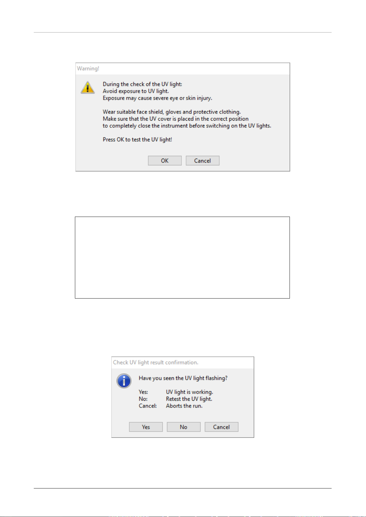
AltoStar® Automation System AM16 – OPERATOR’S MANUAL IVD
2. The first dialog refers to a check of the UV light. This step is performed in order for the user to
check if the UV light is working properly.
Fig. 44.: Warning Dialog
Exact wording of content of the dialog displayed in Fig. 44.:
During the check of the UV light:
Avoid exposure to UV light.
Exposure may cause severe eye or skin injury.
Wear suitable face shield, gloves and protective clothing.
Make sure that the UV cover is placed in the correct position
to completely close the instrument before switching on the UV lights.
Press OK to test the UV light!
3. Additionally, precautions and hazards are mentioned as well as protective measures. Make
sure that all these protective measures are performed and that no collision can happen inside
the instrument (the arm will move during the decontamination process!). Then, select [OK] to
proceed to the UV light test.
4. The UV light will be switched on for a short moment. Observe if the UV light flashes.
Fig. 45.: Check UV Light Result Confirmation
Exact wording of content of the dialog displayed in Fig. 45.:
627108_00 57
Page 64
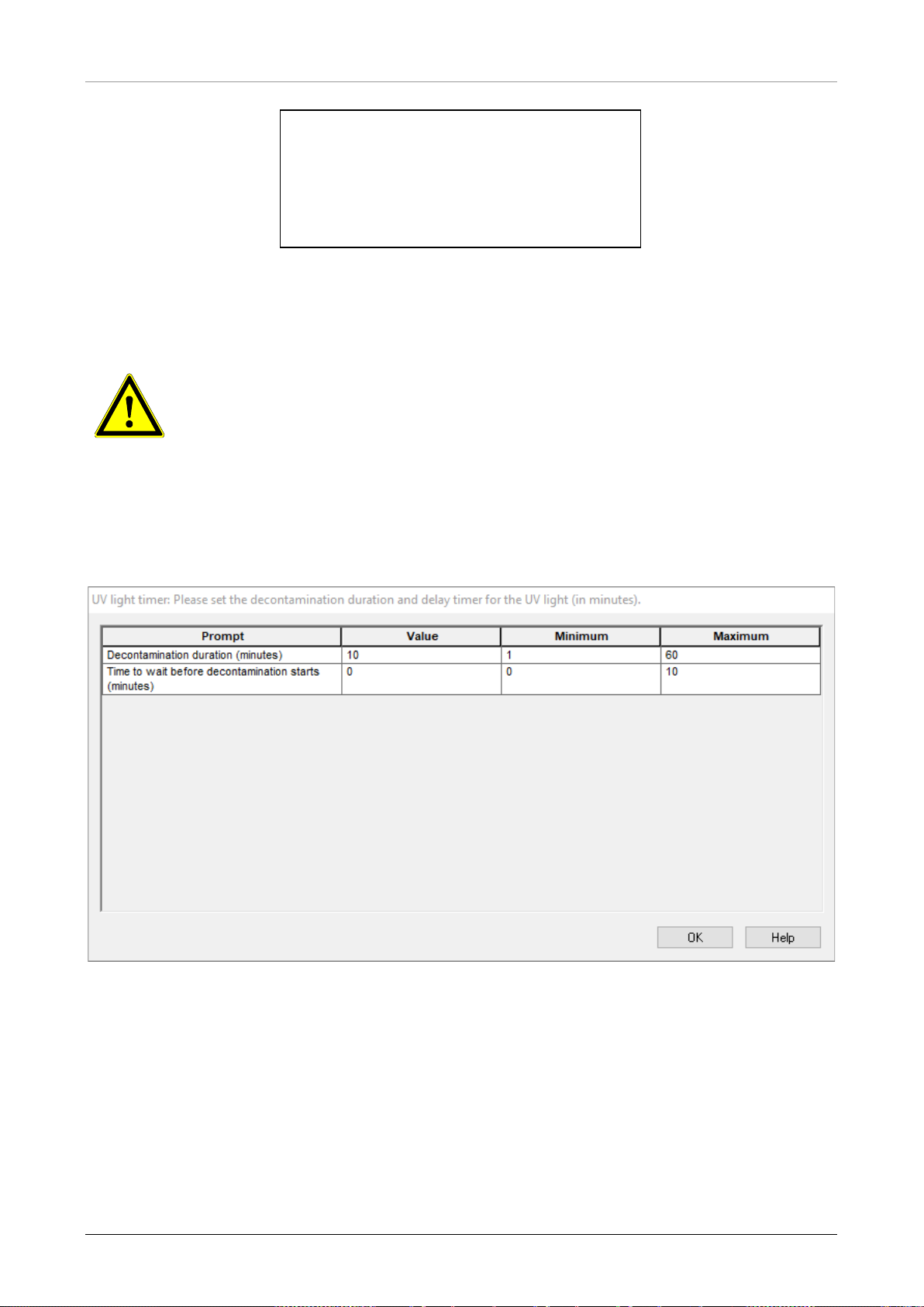
AltoStar® Automation System AM16 – OPERATOR’S MANUAL IVD
If all connections are fine but the UV light flashing can still not be observed, the
Have you seen the UV light flashing?
Yes: UV light is working.
No: Retest the UV light.
Cancel: Aborts the run.
5. If the UV light was shining for a moment, confirm with [Yes]. Else, select [No] for a retest of the
UV light or [Cancel] to abort the run.
ATTENTION
In case the UV light flashing cannot be observed upon several retests, the power
connections should be checked.
UV light may be defective. Please contact altona Diagnostics GmbH in this case.
6. If the UV light flashing could be observed and [Yes] has been selected, the UV light timer
settings dialog is shown.
Fig. 46.: UV Li ght Timer Settings Dialog
7. Enter the desired duration for UV decontamination in the upper “Value” field. The lower
“Value” field can be used to enter the desired delay when the UV irradiation shall start. In this
case, the user can leave the room during this duration until the UV irradiation starts. Whole
numbers are required, otherwise a warning will be displayed and the value has to be changed.
The “Minimum” and “Maximum” values to be used are indicated in the corresponding fields.
8. Select [OK] to proceed.
58 627108_00
Page 65
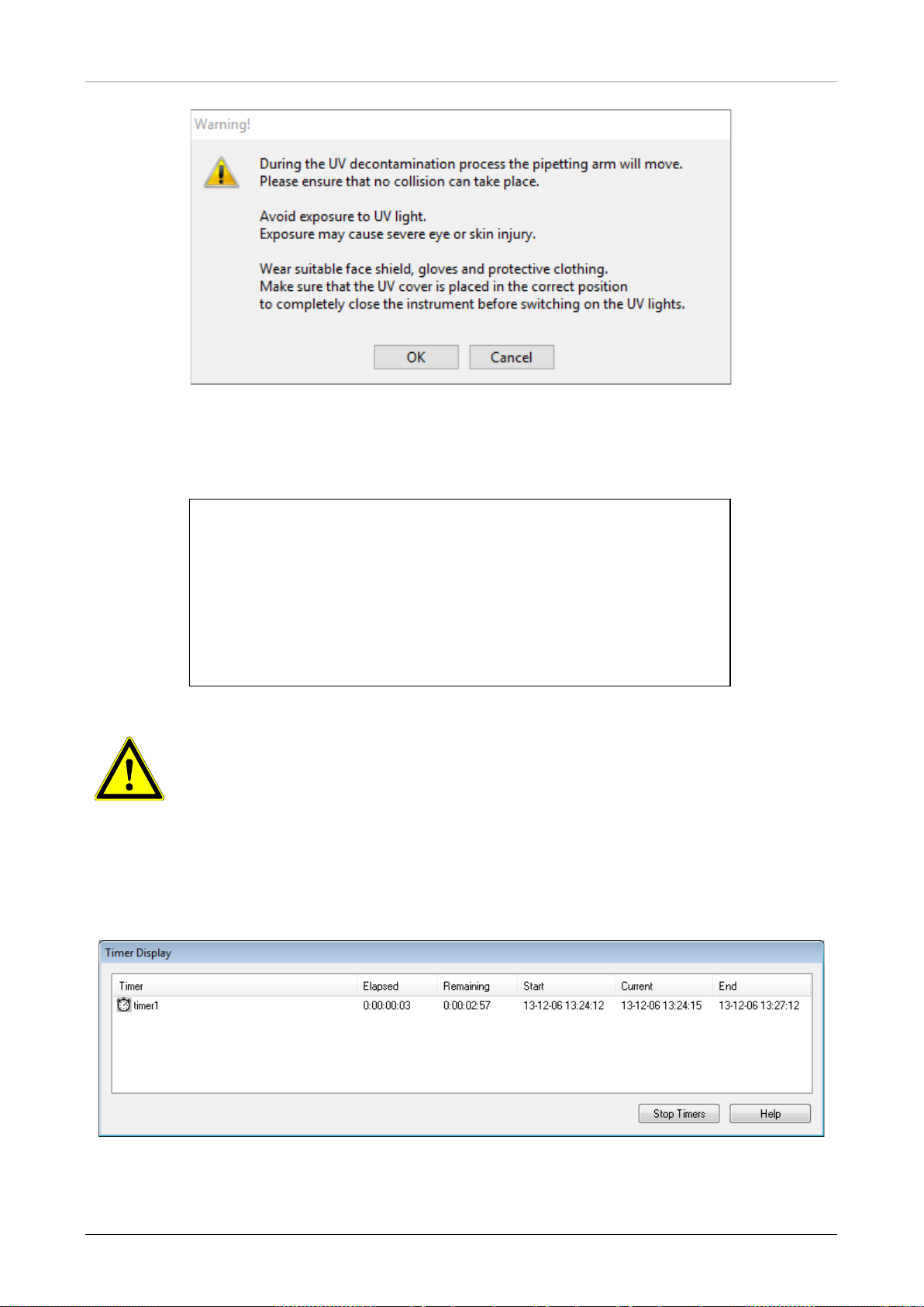
AltoStar® Automation System AM16 – OPERATOR’S MANUAL IVD
strument arm will move and that the
Fig. 47.: Warning Dialog
Exact wording of content of the dialog displayed in Fig. 47.:
During the UV decontamination process the pipetting arm will move.
Please ensure that no collision can take place.
Avoid exposure to UV light.
Exposure may cause severe eye or skin injury.
Wear suitable face shield, gloves and protective clothing.
Make sure that the UV cover is placed in the correct position
to completely close the instrument before switching on the UV lights.
ATTENTION
Make sure that no collision can take place, the in
instrument is closed with the UV covers.
9. A warning is displayed, read it carefully. If no collision can take place and all protective
measures have been performed, press [OK] in order to start the decontamination method.
10. If a delay has been specified, a timer is started showing the time elapsed and the time
remaining. If the button [Stop Timers] is pressed, the timer is terminated and the UV light is
switched on immediately afterwards.
Fig. 48.: Timer Display Dialog
627108_00 59
Page 66
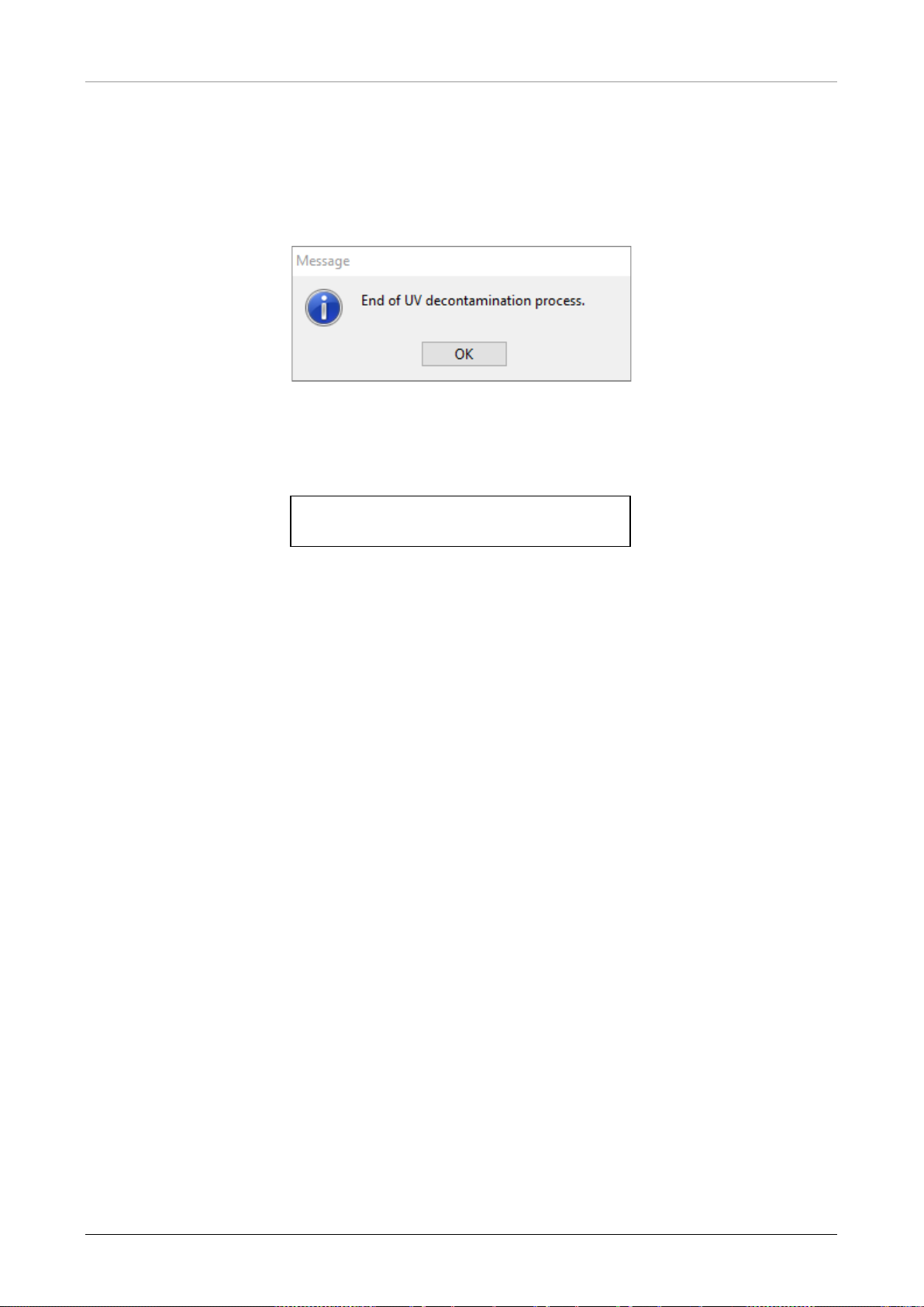
AltoStar® Automation System AM16 – OPERATOR’S MANUAL IVD
11. After the termination of the timer or immediately after pressing [OK] in the UV decontamination
timer settings dialog, if no delay has been defined, the UV light will be switched on
automatically and the Pipetting Arm is moving from left to right in steps every few seconds for
an even irradiation of the workspace.
12. After the decontamination duration specified, the UV light will be switched off, the Pipetting Arm
will stop and the following message appears.
Fig. 49.: End of UV Decontamination Process Dialog
Exact wording of content of the dialog displayed in Fig. 49.:
End of UV decontamination process.
13. To close the UV decontamination method, press [OK]. Afterwards, the UV front cover can be
removed. The UV decontamination method has finished.
60 627108_00
Page 67

AltoStar® Automation System AM16 – OPERATOR’S MANUAL IVD
7 AltoStar® AM16 Verification
The AltoStar® AM16 instrument must be verified by a Hamilton trained field service engineer upon
initial set-up, and thereafter at regular intervals. If any verification procedures are due and have not
been successfully completed, it is not possible to start a run.
The AltoStar
• During the instrument installation
• Twice a year (every 200 days)
• After a repair or service of the instrument
To perform the verification, the appropriate “Field Verification 2” Kit must be used. This kit contains
all the necessary tools to verify the instrument in your laboratory.
For more information about the contents of the verification kit, please consult the corresponding
Field Verification 2 Manual. This manual explains and illustrates the functions to verify and the
entire procedure in detail.
®
AM16 must be verified:
627108_00 61
Page 68

AltoStar® Automation System AM16 – OPERATOR’S MANUAL IVD
62 627108_00
Page 69
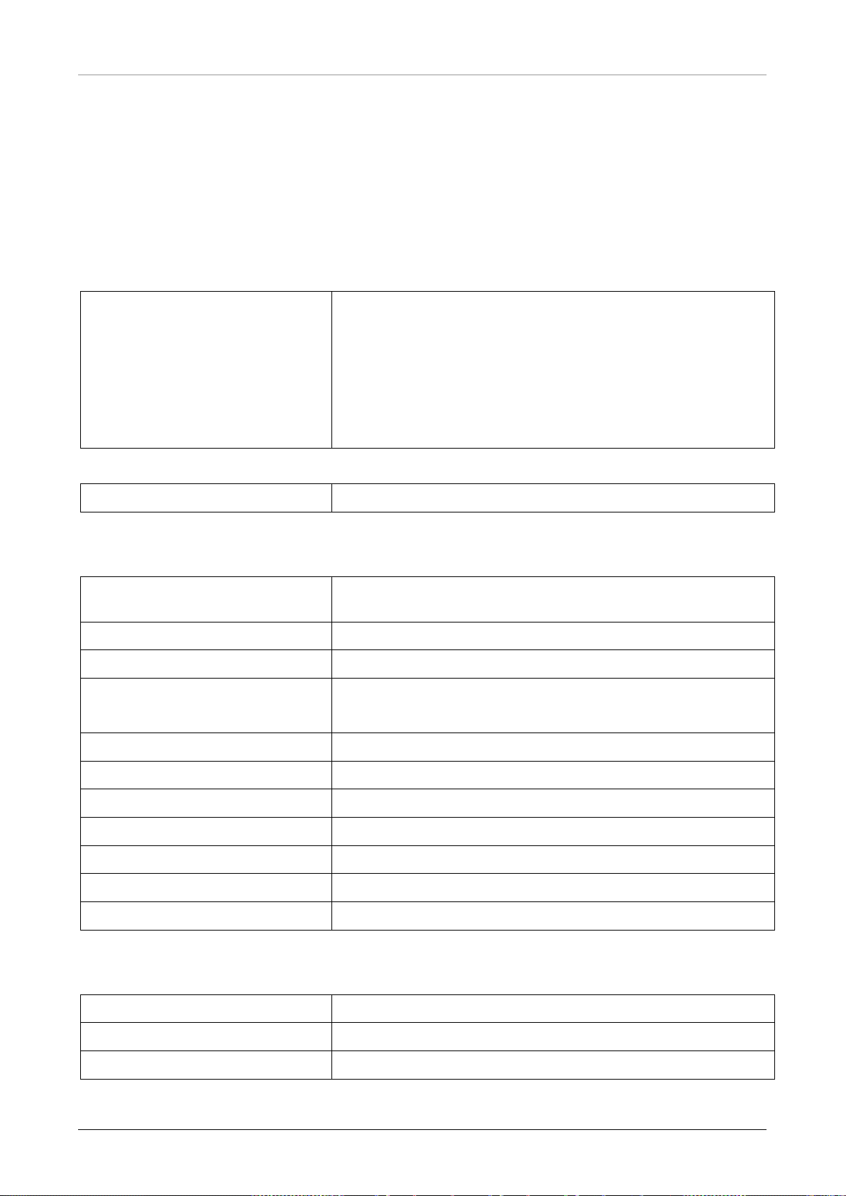
AltoStar® Automation System AM16 – OPERATOR’S MANUAL IVD
8 Technical Specifications
8.1 Basic Instrument AltoStar® AM16
8.1.1 Dimensions and Weight
Dimensions
AltoStar® AM16 Length: 1124mm
Height: 903mm
Depth: 795mm (without loading deck, i.e. transport size)
1010mm (with loading deck)
1200mm (with loading deck and carriers on loading
deck)
Weight
AltoStar® AM16 Approx. 140kg
8.1.2 Operating Data
Maximum Power Consumption ≤ 600VA
Voltage 115 VAC / 230 VAC ± 10%
Frequency 50 / 60 Hz
Delayed Action Fuse 115 V~: 6.3 A (T6.3AL250)
230 V~: 3.15 A (T3.15A250)
Installation Category II
Pollution Degree 2
Temperature Range 15°C – 30°C
Relative Humidity 15% – 85% (no condensation)
Noise Level < 65dBA (regarding EN27779)
Altitude Up to 2000m above sea level
Indoor Use Only
8.1.3 Transportation and Storage
Temperature Range -25°C – +70°C
Relative Humidity 10% – 90% (no condensation, indoors)
Indoor Storage Only
627108_00 63
Page 70
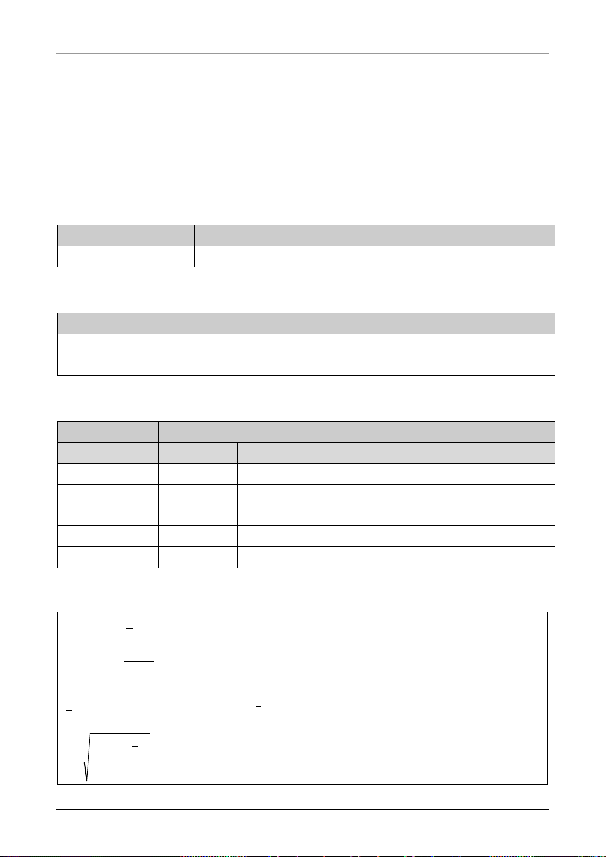
AltoStar® Automation System AM16 – OPERATOR’S MANUAL IVD
%100Pr •=
x
s
ecision
n
i
x
i
t
x
s
x
%100•
−
=
t
t
x
xx
Accuracy
n
x
x
n
i
i
∑
==1
1
)(
1
2
−
−
=
∑
=
n
xx
s
n
i
i
8.1.4 Instrument Life Cycle
The instruments have been designed for a life cycle of 6 years1 under the assumption that the user
maintenance and preventative maintenance is performed at the appropriate intervals.
1
Limiting conditions: Life cycles are related to an average of 5300 pipetting steps per working day.
8.2 Functional Specifica t ions
8.2.1 Work Area
Work Area Dimensions Width (X) Height (Z) Depth (Y)
AltoStar® AM16 675mm (30 tracks) 136mm 465mm
8.2.2 Tip Size for 1000μl Pipetting Channel
Available CO-RE tips Volume
Medium (standard) volume CO-RE tip (with filter) 10 - 300µl
High volume CO-RE tip (with filter) 10 - 1000µl
8.2.3 Pipetting Specification for 1000μl Pipetting Channel
Volume [μl] Tip Size Accuracy Precision
50μl 300μl 1000μl [%] [%]
10 X X --- ± 10 5.0
50 X X X ± 5 2.5
100 --- X X ± 5 2.0
200 --- X X ± 5 1.5
1000 --- --- X ± 5 1.5
Applied statistics:
= number of measured values
= volume dispensed in pipetting cycle [μl]
= nominal volume [μl]
= standard deviation [μl]
= mean [μl]
64 627108_00
Page 71
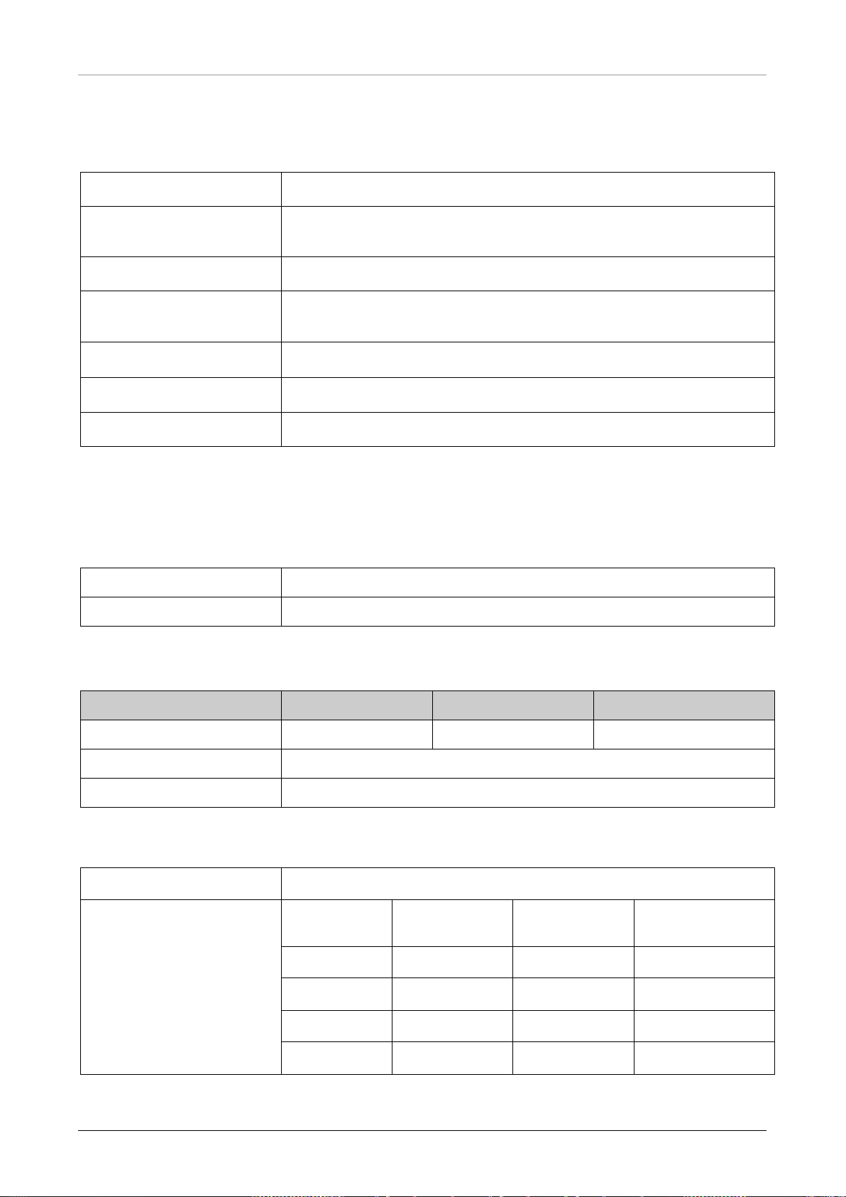
AltoStar® Automation System AM16 – OPERATOR’S MANUAL IVD
2
Test conditions:
The specifications mentioned above are valid under the following conditions and obtained from
measurements at HAMILTON Bonaduz.
Pipetting Channel
Test Method
Accuracy / Precision
Test Size
Test Mode
Test Temperature
Test Fluid
1000μl
Gravimetric testing at Hamilton. The scatter of the test method must be less
than 1/6 of the specified precision (for one channel).
The values given refer to use of 8 pipetting channels.
≥ 10 single pipetting’s per channel with disposable CO-RE tips (pick-up and
dispense, tip used only once) per channel and specified volume.
Volumes ≥ 20µl as jet dispense, < 20µl as (liquid) surface dispense
20 ± 2°C
Deionized water with 0.1% NaCl, 0.01% Tween
8.3 Accessories Specification
8.3.1 CO-RE Grip Specifications
Labware Format Microtiter footprint, plate height ≤ 43mm
Transport Mass 300g (filled deep well plate)
8.3.2 Hamilton Heater Shaker Specifications
Width (X) Height (Z) Depth (Y)
Dimensions 150mm 90mm 105mm
Weight 2500g
Labware
2
Maximum weight including adapter 500g
Temperature Control From 5˚C above ambient temperature to 105˚C
Heater Specifications 3 Set
AltoStar® Processing Plate adapter
temperature
37˚C < 3min ± 1.0˚C ± 2.0˚C
60˚C < 10min ± 1.5˚C ± 3.0˚C
Time to reach
set temperature
Deviation to
set temperature
Deviation on
heating plate
90˚C < 20min ± 2.0˚C ± 4.0˚C
105˚C < 35min ± 2.5˚C ± 5.0˚C
3
Measured with HHS equipped with universal flat bottom adapter
627108_00 65
Page 72

AltoStar® Automation System AM16 – OPERATOR’S MANUAL IVD
Shaking Directions Clockwise and counter-clockwise
Shaking Orbit 2.0mm, 3.0mm
Maximum Rotation Speed -2500 rpm (with 2.0mm orbit)
-2400 rpm (with 3.0mm orbit)
Shaker Specifications 4 Set rotation speed Deviation to set rotation speed
30 rpm ± 1.5 rpm
500 rpm ± 25 rpm
1000 rpm ± 50 rpm
2000 rpm ± 100 rpm
4
Measured with HHS equipped with universal flat bottom adapter
Operating Data Maximum power consumption 140 VA
Installation category II
Pollution degree 2
Temperature range 15˚C – 30˚C (operation)
-25˚C - +70˚C (storage, transport)
Relative humidity 15% - 85% (operation)
10% - 90% (storage, transport)
No condensation
Noise level < 65dBA at max speed
Altitude Up to 2000m above sea level
Indoor use only
Communication CAN via TCC connector or USB
66 627108_00
Page 73

AltoStar® Automation System AM16 – OPERATOR’S MANUAL IVD
Maximum 20 character s excluding star t, stop and che ck c haracters, dependi ng on the
The barcode print m ust be of a high qualit y. A printed barcode with an ISO/EC 15416
grade 4 (A) or 3 ( B) is required. Offset, typogr aphic, intaglio a nd flexographic printing
8.4 Autoload: Barcodes and Reader Specifications
Carriers, containers, racks and tip racks will be identified by a barcode, which a reader, mounted
on the Autoload slide, scans.
8.4.1 Barcode Symbologies
The following barcode symbologies can be detected by the system:
• Code 128 (subset B and C)
• Code 39
• Codabar
For the highest reading safety HAMILTON recommends:
1. To use barcode type Code128 (subset B and C)
2. Disabling the unused barcode types in the System Configuration Editor
8.4.2 Reading Accuracy
The rate of inaccurate readings of sample plates and container barcodes is less than 1 ppm.
The above-mentioned specification is valid under the following conditions:
• Barcode symbology module: ISBT standard
• Code density: 0.0065” (0.1651mm)
• Print quality: as def ined in section “Barcode Specifications
“
• Recognized errors are defined as an accurate reading
8.4.3 Barcode Specifications
Length of string
Code Density,
Tolerance
code length (see label dimensions).
Minimum module width (X dimension) including a print tolerance:
≥ 0.0065" (0.1651mm)
Maximum module width (X dimension) including a print tolerance:
≤ 0.02" (0.508mm)
Best reading performance with X dimension between 0.0075” (0.1905mm) and 0.01"
(0.254mm)
Check character Code 128 One character
Code 39 None
Codabar None
Quiet Zone ≥ 10 times the X dimension, but at least 3mm.
Print quality
are suitable. Mechanical dot matrix and thermo matrix printing are not suitable.
The surface may be treated, sealed or plastic-coated.
627108_00 67
Page 74
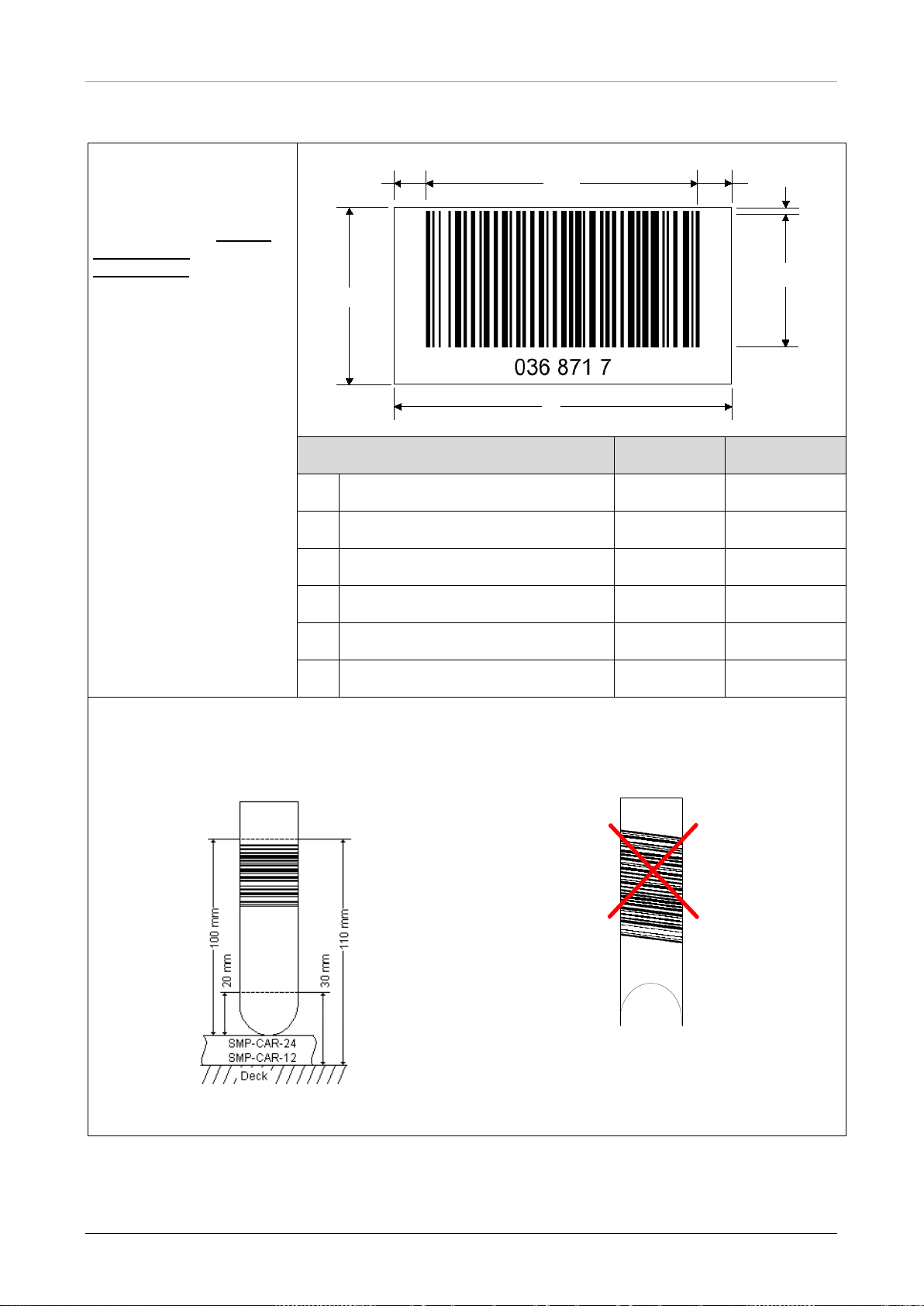
AltoStar® Automation System AM16 – OPERATOR’S MANUAL IVD
B
C
A
D
E
F
C
8.4.4 Sample Barcodes
Barcode Specifications
For general barcode
specification, see
8.4.3 Barcode
Specifications.
Chapter
A Label length - 80mm
Dimension Min. Max.
B Code length - 74mm
C Quiet zone 3mm D Label width 12mm E Code width 12mm F Distance from code to label edge - 1mm
Positioning Barcode Labels
The label must be glued within a range of between 20mm to 100mm from the bottom of the tube.
The label must fit tightly at an angle of approximately 90° to the tube.
The label must fit tightly over its whole length.
68 627108_00
Page 75
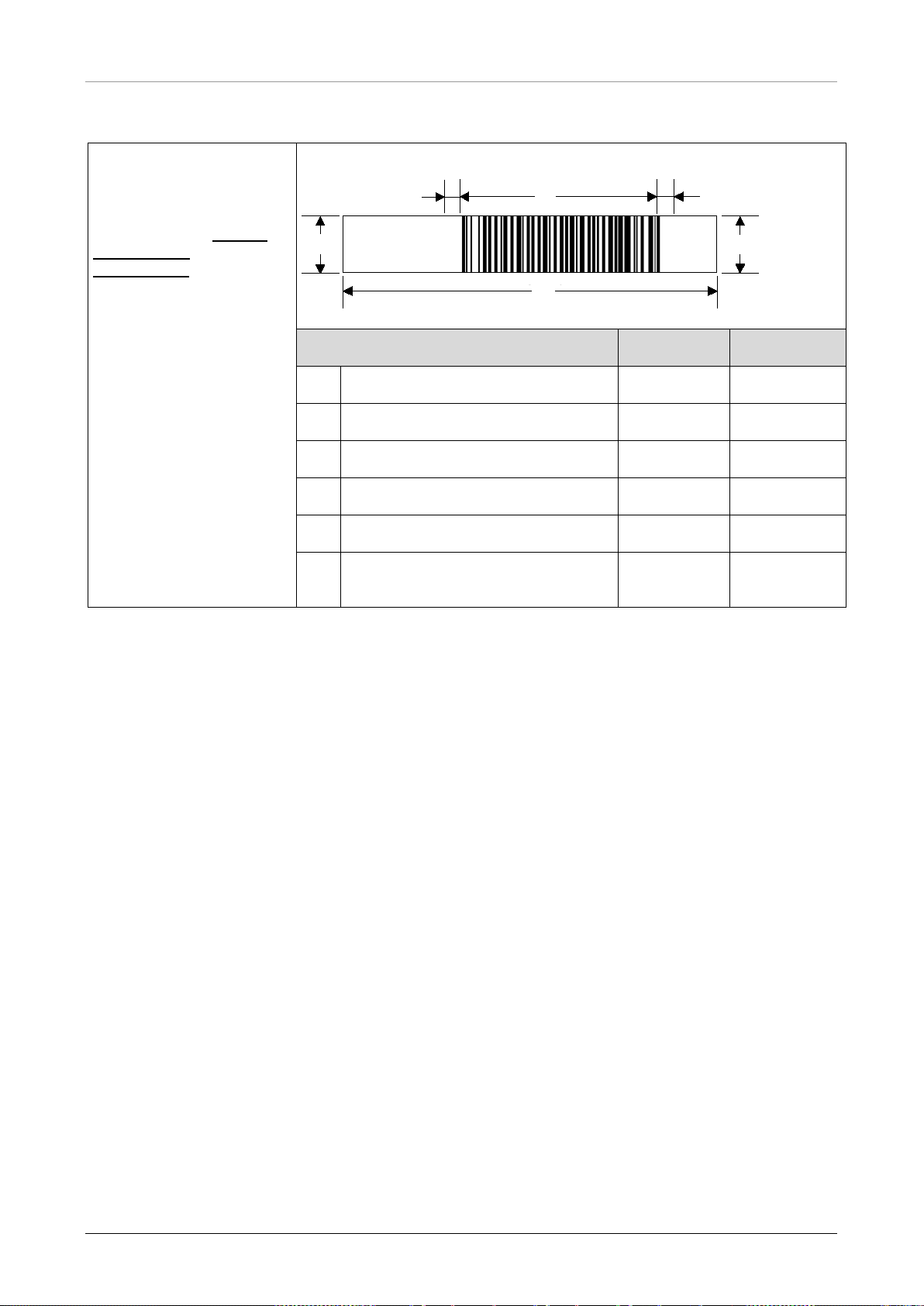
AltoStar® Automation System AM16 – OPERATOR’S MANUAL IVD
A
B
C
C
E
D
036 871 7
8.4.5 Plate Barcodes
Label Specification
For general barcode
specification see
8.4.3 Barcode
Specifications.
Chapter
Dimension Min Max
A Label length - 66mm
B Code length - 30mm
C Quiet zone 3mm D Label width 10mm E Code width 7mm -
Distance from code to label edge (if
F
necessary)
- 1mm
627108_00 69
Page 76
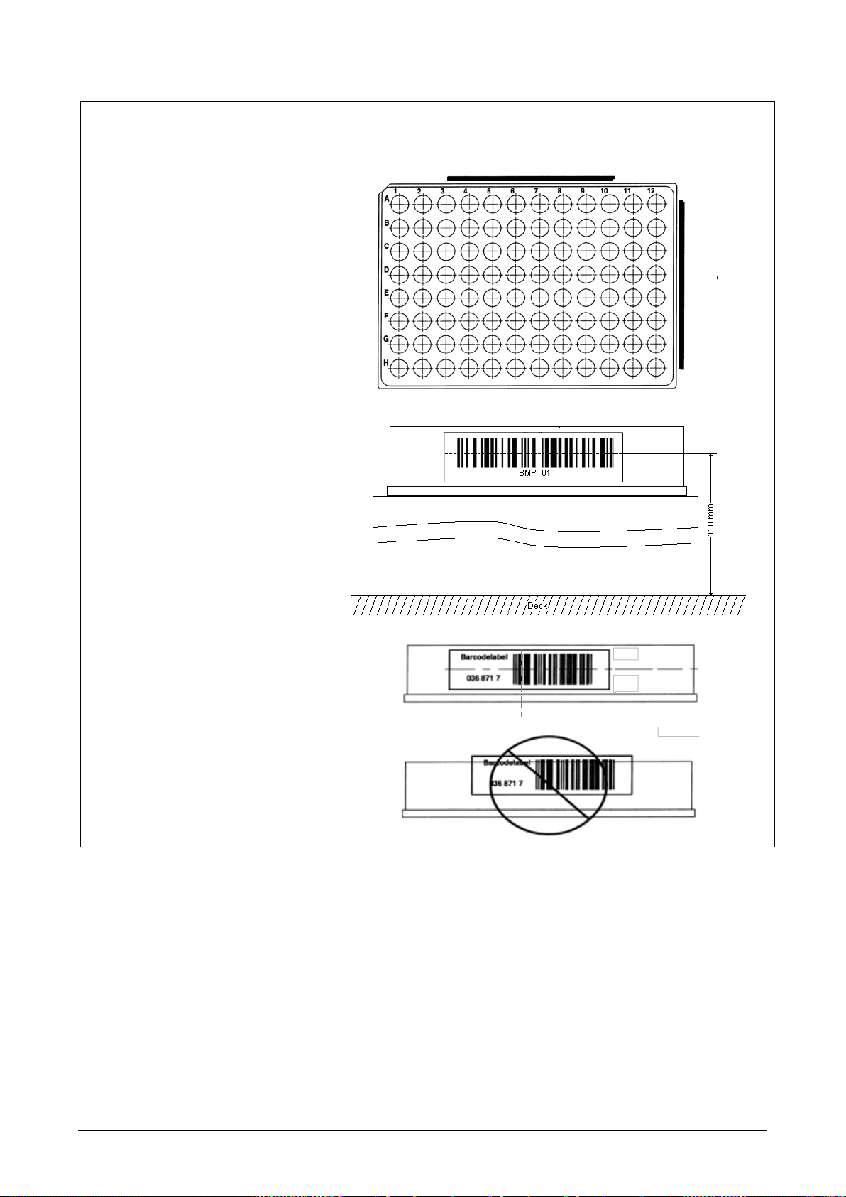
AltoStar® Automation System AM16 – OPERATOR’S MANUAL IVD
side B
side A
Positioning Barcode Labels:
The barcode must fit on side A or
Side B of the plate.
The barcode must be positioned
in the middle of the plate.
The barcode must be centered
and parallel to the edge of the
plate.
The barcode label must not
protrude above or below the
edge of the plate.
70 627108_00
Page 77

AltoStar® Automation System AM16 – OPERATOR’S MANUAL IVD
9 Appendices:
9.1 Appendix A:
9.1.1 Regulatory Affairs
CE conformity is issued and maintained for the AltoStar® AM16. See the Declaration of Conformity
provided with the instrument as well as the information in the following sections.
9.1.2 Radio Interference (USA and Canada)
This equipment has been tested and found to comply with the limits for a Class “A” digital device,
pursuant to both Part 15 of the FCC Rules and the radio interference regulations of the Canadian
Department of Communications. These limits are designed to provide reasonable protection
against harmful interference when the equipment is operated in a commercial environment. This
equipment generates, uses and can radiate radio frequency energy and, if not installed and used in
accordance with the present user manual, may cause harmful interference to radio
communications. Operation of this equipment in a residential area is likely to cause harmful
interference, in which case the user will be required to correct the interference at his own expense.
Pursuant to the Canadian Radio Interference Regulations, ICES-001 Notice for Industrial, Scientific
and Medical Radio Frequency Generators, this ISM apparatus meets all requirements of the
Canadian Interference-Causing Equipment Regulations. Please note that this requirement is only
for generators which operate at over 10,000 Hz.
9.1.3 In Vitro Diagnostics
The AltoStar® AM16 is an In Vitro Diagnostic Device and therefore regulated by the Directive
98/79/EC of the European Parliament and of the Council of 1998-10-27 on in vitro diagnostic
medical devices.
9.1.4 Applied Company Quality Management Systems
Applied company quality management systems EN ISO 9001 and EN ISO 13485 Certification
Body is TÜV Rheinland LGA Products GmbH, Am Grauen Stein 29, D-51105 Köln-Poll, Germany.
9.1.5 Declaration of Conformity
Each individual instrument includes a Declaration of Conformity showing the directives and
standards it conforms with.
9.1.6 Declaration of Quality
Each individual instrument includes a Declaration of Quality. It will be filled out according to the
results of the final inspection and is valid for the specific instrument serial number entered.
627108_00 71
Page 78

AltoStar® Automation System AM16 – OPERATOR’S MANUAL IVD
9.1.7 WEEE Declaration
9.1.7.1 Recycling of an AltoStar ® AM16
Recycling of a AltoStar® AM16 Instrument in accordance to EC directive WEEE
The European Community requires from manufacturers to organize the disposal and waste of
electrical and electronic equipment (WEEE). For this reason, Hamilton Bonaduz AG took part in an
initiative to organize the disposal of ML STAR products since AltoStar® AM16 is based on the ML
STAR IVD it will run through the same organization, a European disposal network called RENE.
RENE is the largest recycling network for the disposal of electronic equipment in Europe. The
mission of RENE is a European-wide, WEEE-compliant, high quality recycling for electrical and
electronic equipment through a dense network with both innovative and SMB-sized partner
companies. As a result, Hamilton Bonaduz AG gets a turn-key-solution that includes all processes
from treatment of incoming orders over collection, logistics and recycling down to reporting and
management of material flows.
Hamilton offers a WEEE process in collaboration with Toolpoint and RENE AG:
• Request for the collection of the Hamilton instrument via Toolpoint Home Page
(www.toolpoint.ch)
• Completion of the decontamination confirmation form
• Preparation for transport: packing
• Activation of the recycling order
• Archiving of the decontamination confirmation
• Disposal of the instrument
Responsibilities
Ordering party Decontamination
Note: The cost for d econtami nation and pre parati on for
shipment is paid by the ordering party. On request,
HAMILTON offers to take care for that part of the
recycling process.
RENE Transport
Toolpoint Registration
HAMILTON Organize the disposal acc or di ng to the WEEE directive
9.1.7.2 Recycling Process
Preparation for transport
Disposal
Invoice the disposal to HAMILTON
1. Request for disposal of the instrument
Access to the order registration is given by the Toolpoint homepage www.toolpoint.ch
Recycling Order registratio n form
2. Completion of the Decontamination form
Once the form has been completed, the request for disposal is automatically activated and
transferred to Toolpoint. The confirmation of the order will be sent to the registered contact
person.
72 627108_00
Page 79

AltoStar® Automation System AM16 – OPERATOR’S MANUAL IVD
3. Decontamination
The responsibility for decontamination remains at the ordering party. It is mandatory to sign the
decontamination form and send a copy electronically to Toolpoint. Toolpoint forwards the
documentation to RENE, who is in charge of instrument disposal.
4. Packing / Preparation for shipment
For the transportation of instruments with a weight of over 30kg need to be fixed on a euro
pallet. Instruments below 30kg can be packed in a cardboard or plastic box. A signed copy of
the decontamination form needs to be added to the outer part of the shipping box or instrument.
Refer to the Technical Note Recycling Passport AltoStar® AM16 in accordance to EC directive
WEEE”.
9.1.8 RoHS Compliance
Since July 2016 AltoStar® AM16 instruments are in compliance with RoHS II Directive 2011/65/EU
of the European Parliament and of the Council of 8 June 2011, on the restriction of the use of
certain hazardous substances in electrical and electronic equipment (RoHS II) and its amendments.
627108_00 73
Page 80

AltoStar® Automation System AM16 – OPERATOR’S MANUAL IVD
9.2 Appendix B: Glossar y
Term Definition
Autoload Hardware assembly that enables automatic loading of the AltoStar® AM16. It
consists of a loading head movable in Y direction, which draws the carriers into
the AltoStar
Barcode Reader Device for reading sample/plate barcodes. Part of the Autoload.
Carrier Unit for loading plates, containers, tubes and tips on the AltoStar® AM16 deck.
Loading process is carried out by the Autoload unit.
Deck The work surface (work area) of the AltoStar® AM16. The area where the
pipetting channels perform liquid handling or transport steps. The deck is divided
into tracks, which are occupied by labware.
Dispense To distribute quantities of liquid from a pipetting device.
Firmware Lower level program code that is carried out on the processors of the AltoStar®
AM16 Instrument.
®
AM16 and reads the barcodes on them.
Front Cover Protective covering for the AltoStar® AM16 Instrument, featuring a hinged front
window made of transparent Plexiglas. With this option and assembly, the work
surface of the AltoStar
user intervention and other outside influences (such as dust). At the same time,
it protects the user from the movements of the AltoStar
®
AM16 is covered in such a way that it is shielded from
®
AM16.
HHS Hamilton Heater Shaker. Unit to heat and shake the AltoStar® Processing Plate.
Instrument Hardware of the AltoStar® AM16 (mechanics, electronics, and firmware)
Labware Refers to movable items to be placed on the A lto Star AM16 deck, such as
carriers, containers, or racks.
Loading Tray Hardware unit. The carriers can be placed on it and held outside the AltoStar®
AM16. The loading tray is attached to the AltoStar
®
AM16, to support the
automatic loading and unloading process.
LIMS Higher level data processing system, generally known as Laboratory Information
Management System, also LIS.
LLD
Liquid Level Detection – Detection of liquid surface achieved by capacitive signal
detection.
Loading/Unloading The process by which plate, tube and tip carriers are brought on and off the
AltoStar
®
AM16 deck. This is automatically performed via the Autoload unit.
AltoStar® Connect SW
Software to run the AltoStar
®
AM16.
Pipetting Transfer of liquids from one container to another.
Pipetting Arm Assembly equipped with the pipetting device and/or plate hand ler, as well as the
common X-drive.
Pipetting Channel Hardware assembly including the function of picking up a tip aspirating,
dispensing, tip eject, liquid level detection and the Y/Z-movements
74 627108_00
Page 81
AltoStar® Automation System AM16 – OPERATOR’S MANUAL IVD
Term Definition
Pooling Pipetting of different liquids in one well; 1, 2, 3…to n
P/N Part number
Sample Refers to a liquid in a unique identified container which is to be processed.
TADM Total Aspiration and Dispense Monitoring. The pressure inside each individual
pipetting channel is monitored during aspiration and di s pens in g.
Tip Disposable tip for pipetting
Tip Rack Frame that holds the tips.
Tip Waste Container for ejected tips.
Tube A container for liquid, usually having a circular cross-section, and a cylindrical
length section.
Waste Container A device on the AltoStar® AM16 deck to collect used disposable tips.
Well The individual container of a microtiter plate or a Deep Well Plate.
Work Area The area of the AltoStar® AM16 to which access is provided during the
processing. Elements to be pipetted or handled are placed in this area.
9.3 Appendix C: Manual Update Information
Modifications of the AltoStar
Date of Change Revision Description of Change
October 2017 00 Initial Version
®
Automation System AM16 Operator’s Manual are listed here.
627108_00 75
Page 82

AltoStar® Automation System AM16 – OPERATOR’S MANUAL IVD
9.4 Appendix D: Forms
The appendix contains the following forms:
• Instrument update information record: to be used to record the instrument configuration
after software and firmware upgrades have been installed on the AltoStar
• Maintenance and Preventive Service Maintenance Log forms: to be used for recording
details of maintenance carried out on the AltoStar
®
AM16.
®
AM16.
76 627108_00
Page 83

AltoStar® Automation System AM16 – OPERATOR’S MANUAL IVD
AltoStar® AM16
Instrument Upgrade Record
Computer Serial No.: __________________________
Instrument Serial No.: ………………………
Installed by Date Initials Remarks
Supervisor
Check
627108_00 77
Page 84

AltoStar® Automation System AM16 – OPERATOR’S MANUAL IVD
AltoStar® AM16 Maintenance Log
Month/Year: ……………….
Laboratory Name: ………………………
Instrument Serial No.: ………………………
Daily Maintenance
Instrument deck clean
Waste container empty
Weekly Maintenance
All carriers clean
Carriers intact
Instrument deck clean
Waste container empty and clean
Nothing else contaminated
1 2 3 4 5 6 7 8 9 10 11 12 13 14 15 16 17 18 19 20 21 22 23 24 25 26 27 28 29 30 31
Check each item and initial the appropriate box opposite 'Daily' and 'Weekly' upon completion of each maintenance.
Date/Initials of Supervisor: .......................................................................
78 627108_00
Page 85

AltoStar® Automation System AM16 – OPERATOR’S MANUAL IVD
AltoStar® AM16
Preventative Service Maintenance Lo g
Laboratory Name: ………………………
Instrument Serial No.: ………………………
Date Notes Initials Supervisor Check
627108_00 79
Page 86

AltoStar® Automation System AM16 – OPERATOR’S MANUAL IVD
HAMILTON Bonaduz AG
Via Crusch 8
CH-7402 Bonaduz
Switzerland
Tel. +41 81 660 60 60
Fax +41 81 660 60 70
[email protected]
http://www.hamiltoncompany.com
80 627108_00
 Loading...