


Hamilton 9505936 Maintenance Manual
Hamilton
Installation
Operation
and
Maintenance
Manual
sink
Unit
No.
9505936
Sink
NSN:
Unit
Number:
9505996
6545-01-163-1899
Hamilton
1316
Two
Code
18th
Rivers,
Number:
Industries,
Inc.
Street
WI
54241
26954
Form
Issue
Revision:
Number:
Date:
PL-410-3
October
4
1,
1992
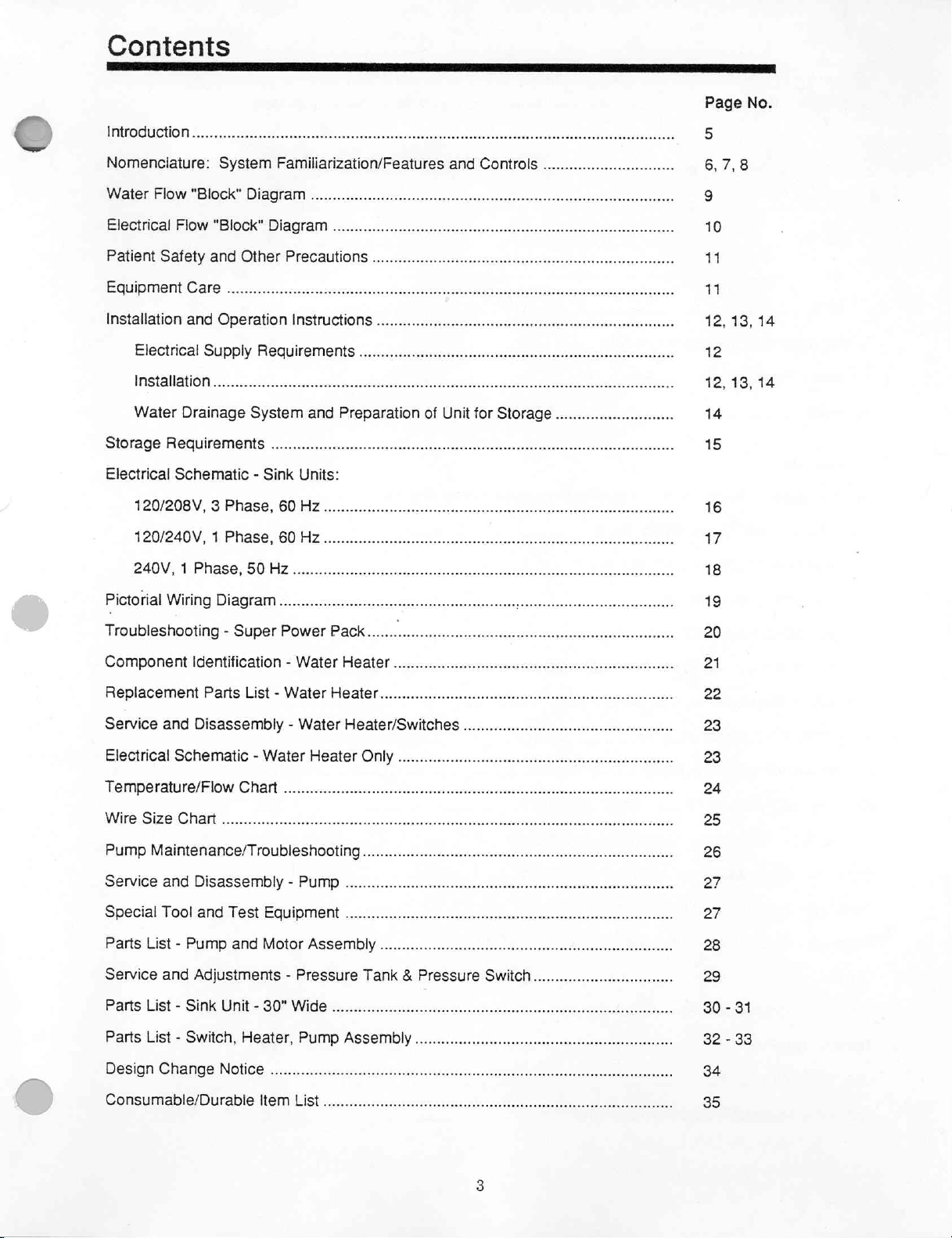
Contents
Introduction
Nomenclature:
Water
Patient:
Equipment
Installation
Flow
Electrical
Flow
Safety
Electrical
"Block"
Care
and
Supply
Πο
Water
Storage
Electrical
120/208V, 3 Phase,
120/240V, 1 Phase,
240V; 1 Phase.50
Pictorial
Drainage
Requirements
Schematic - Sink
WiringDiagram...........................
System
Diagram
"Block"
Diagram
and'Other
Operation
Requirements
System
Familiarization/Features
............
and
Controls
..............................
nen
renerne
rn
rn
ee
Precautions
Instructions...
sise
ο
ο ο ο
and
Preparation
of
линии
ο
Unit
for
Storage
...........................
mers
seeren
dere
νο
vsere
11
12,
12
12,
14
15
13,
13,
14
14
Units:
60
Hz...
60 月 Ze
ssascsscsccpsczsnssciacitisssssecdsecerenenencnenseenensseraecngenenrsenneenenntenneess
een
有
16
17
18
19
Troubleshooting - Super
Componentidentification-WaterHeater.................................................
Replacement
Service
Electrical
Temperature/Flow
MO
Parts
and
Disassembiy
Schematic - Water
AAA
PümpMaiménance/TrOUDISSROO
Service
Special
Parts
Service
Parts'List = Sink
Parts
Design
and
Disassembly - Pump
Tool
and
ТезЕ
List - Pump
and
and
Adjustments - Pressure
Unit
List - Switch,
Change
Notice
Power
List - Water
-WaterHeater/Switches.............................................
Chart
idee
Едшриейи
Motor
=-30"
Wide
Heater,
PUMP
лесопарка
Pack.......
Heater
Heater
ra
i
Only
NY...
.....................
Assembly
Tank & Pressure
ο
ASSEMDIY
ου
.................
линии
Switch
ーー
oeeeee
eee
ce
cn
NE
иена,
ne
ene
eee
ne
nene
................................
iran
ii
20
21
22
23
23
24
25
26
27
27
28
29
30 - 31
32 - 33
34
Consumable/Durable
Item
List...
LE
blender
35
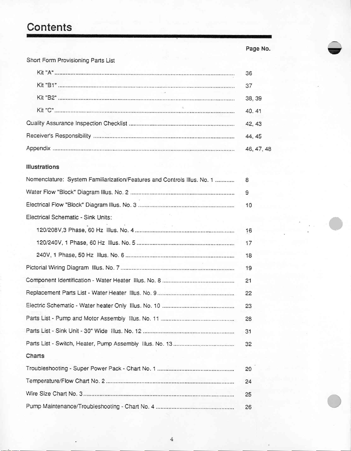
Contents
ER
Short
Form
Provisioning
E
Parts
List
O
B
E
EEN
Page
No.
1
Kit
"Ba"...
КИ
"С"
Quality
Receiver's
PDG
Assurance
人
ee
e
Inspection
Responsibility
Checklist
....
eeoeeeee
ee
Pete o tet
eee
né
a
36
37
38,
40.
42,
44,
46,
Illustrations
Nomenclature:
WaterFlow"Block"DiagramIllus.No.2...............................................
Electrical
Electrical
120/208V,3
Flow
System
"Block"
Familiarization/Features
Diagram
Schematic - Sink
Phase,
60
Illus.
Units:
Hz
Illus.
and
Controls
No. 3 5
ölen
No. 4 аишиашиниы
Illus.
No. 1 ............
a
Bose
8
g
10
16
39
41
43
45
47,
48
120/240V, 1 Phase,
240V, 1 Phase,
Pictorial
Component
Wiring
Identification - Water
Replacement
Electric
Parts
Parts
Parts
Schematic - WaterheaterOnly
List - Pump
List - Sink
List - Switch,
Diagram
Parts
and
Unit - 30"
60
Hz:
50
Hz
IIIus.
Illus.
List - Water
Motor
Assembly
Wide
Heater,
Pump
INSLNOS
No.
No.
7
Heater
Heater
Illus.
Assembly
ito
6...
Illus.No.8.............................................
nene
eee
nenene
Illus.No.9................................................
Illus.No.10.........................................
Illus.No.11...........................................
NO.
12
Illus.
No.
18...
rant
rrrernnne
Charts
Troubleshooting-SuperPowerPack-ChartNo.1..................................
Temperature/Flow
Chart
NO 2 せろ
We
Pump
Maintenance/Troubleshooting-ChartNo.4.............................................
17
18
19
21
22
23
28
31
32
20
24
25
26

introduction
Scrub
sink
unit
for a field
dispenser,
provide
cold
electrical
surgical
Sink
facilities
opment
control
The
which
pounds.
handle
The
pump
adjustable
water,
hot
inlet
soap.
unit
provides
within
of
x-rays.
handles
cabinet
extends
Four
are
used
actuator
to
water
and
cord.
pressurized
the
mdeical
The
on
water
provides
20"
above
carrying
to
secure
for
the
hospital
supply
cold
water
temperature.
faucet
Additional
facility.
unit
also
mixing
an
overall
the
sink
handles,
work
soap
dispenser
consists
pressure,
Unattached
handles,
items
required
cold
and
Provides
provides
faucet
unit
size
top
backsplash.
two
recessed
counters
is
foot
of a cabinet
pressure
waste
hose
but
heated
water
tempered
surgical
and
foot
of
30-1/8"
in
950S927
operated;
with
tank
items
furnished
assembly,
not
supplied
for
use
water
scrub
facilities
operated
wide x 24"
Cabinet
each
side,
or
950S928
the
dispensing
removeable
to
provide
water
are
in
field
for
cleansing
with
soap
dispenser.
deep x 40"
average
and
four
to
casters, a stainless
uniform
are
external
medical
necessary
weight
support
the
nozzle
mixing
supply
water
of
high,
unit.
flow
faucet
hose
facilities.
equipment
sterile
excluding
is
260
bars,
is
on
rate
and a water
with
and
filler
supply,
Provides
and
controls,
pounds
one
recessed
the
unit's
steel
sink,
heater
gooseneck
assembly,
electrical
for
supply
sanitary
assistance
such
as wrist
the
faucet
with a maximum
top.
gooseneck,
above
soap
to
hot
and
and
waste
in
devel-
each
and
of
265
Water
tank
limit,
pressure
The
KW
is
The
supply
to a preset
approximately
limits
water
heater
at
230V
50/60
adjustable
water
using a rheostat
heater
pump
Phase, 2 Wire.
Recommended
(capable
Shipping,
All
personnel
common
better
Heavier
product.
of
furniture
are
carriers.
utilization
items
Our
measuring
Handling
products
loaders
is
powered
upper
limit,
30
psi
are
adjustable.
is
an
in-line
Hz.
and
will
operate
test
equipment
150
have
instructed
The
of
are
exception
the
truckload
floor
to
loaded
are
by a 1/3
approximately
minimum,
heater
will
operate
in a solid
on
the
is
as
degree
and
directional
follow
F).
Storage:
the
to
the
space.
with
lighter
instructed
not
h.p.
(minimum)
60
psi
the
pump
will
which
functions
at
208V,
state
sircuit.
following
follows:
arrows
power
Volt
which
directional
directional
items
to
load
heavy
110/220V
maximum.
automatically
only
when
50/60
Hz,
with
Maximum
supplies:
Ohm
Meter,
indicate
arrows
loaded
when
arrows
on
items
is
allowed
top.
on
50/60
When
the
repressurize
water
wattage
water
temperature
120/208V,
Continuity
how
the
product
loading
when
Heavy
lighter
Hz.
tank
is
flowing
reduced
60
Tester
truck
“Topping”
items
weight
motor, and
pressure
the
tank.
through
accordingly.
is
pressurizes
is
reduced
The
the
150°
F.
upper
heater.
Water
Hz, 1 Phase, 3 Wire;
and
Immersible
is
to
be
loads,
can
be
loaded.
containers
freight
double
Hamilton
or
with
decked
items.
the
pressure
to a preset
and
lower
It
is
rated
temperature
240V,
50
Thermometer
loading
assisting
lighter
on
the
"LIL"
cartons
same
lower
at
Hz,
for
4
1
All
truckloads
The
above
Recommended
Warranty:
All
product
of
one
(1)
year
repair
or
replace,
warranty
made
excludes
by
others.
must
be
secured
instructions
should
Storage
purchased
from
at
any
on
date
its
expense,
damage
at
also
Climate
this
contract
of
acceptance
the
rear
apply
Limits
Are:
are
by
including
or
malfunction
and
pictures
to
storage.
Never
Temperature: 0 Degree
Humidity:
warranted
the
transportation
to
government.
due
to
are
taken
place
be
free
of
During
and
labor,
accident,
as a permanent
heavier
items
Fahrenheit — +130
5%
Min.
Humidity — 95%
defect
alteration,
the
any
in
material
warranty
part
abuse,
record.
on
lighter
period
or
product
negligence,
ones.
and
workmanship
Hamilton
found
Degree
Max.
to
be
misuse,
Fahrenheit
Humidity
for a period
Industries
defective.
or
repairs
will
This
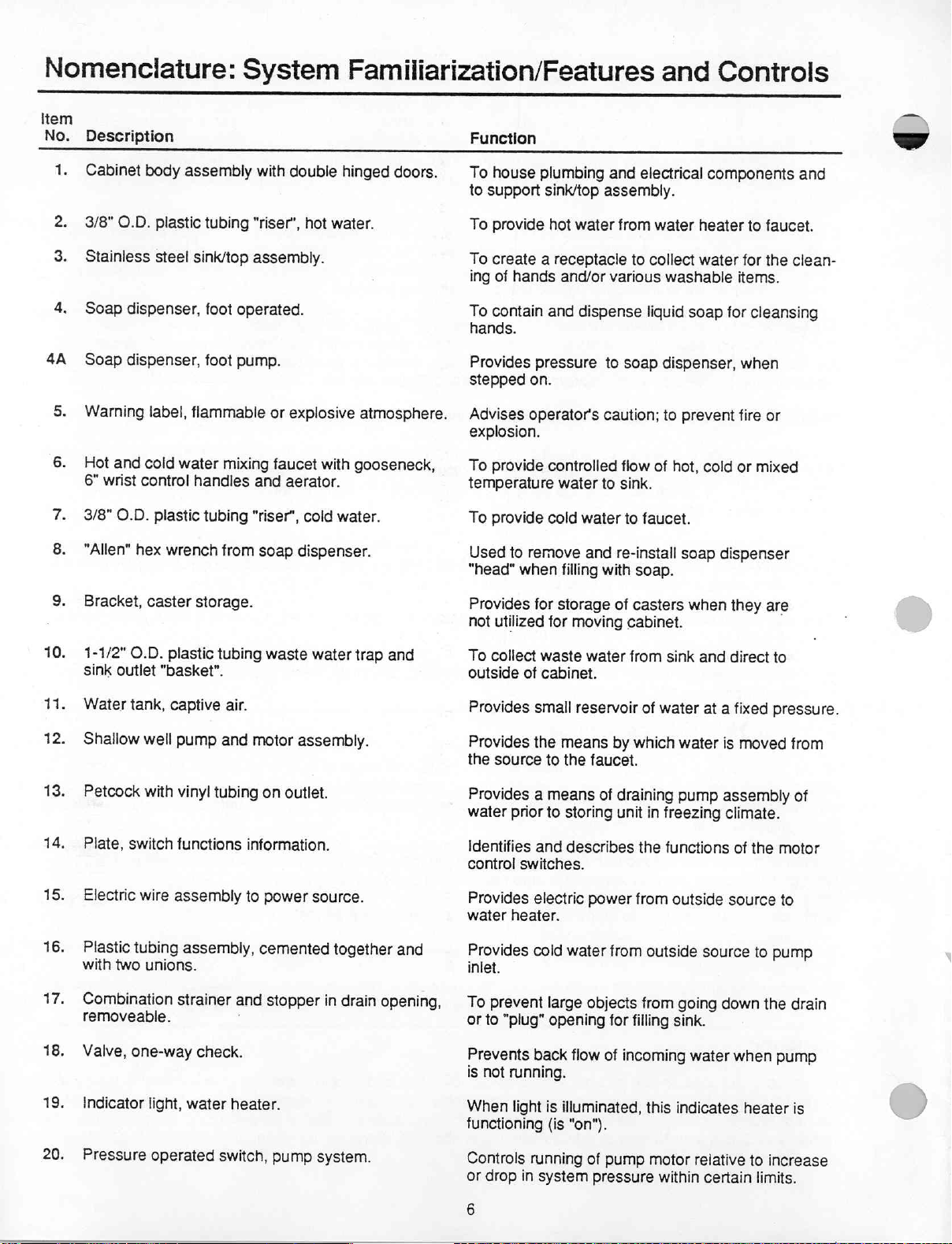
Nomenclature:
Item
No.
Description
1.
Cabinet
2.
3/8"
3.
Stainless
4.
Soap
4A
Soap
5.
Warning
6.
Hot
6"
7.
3/8"
body
O.D.
dispenser,
dispenser,
and
cold
wrist
control
O.D.
assembly
plastic
steel
sink/top
label,
flammable
water
handles
plastic
System
tubing
foot
operated.
foot
pump.
mixing
tubing
with
double
"riser",
hot
assembly.
or
explosive
faucet
and
aerator.
"riser",
cold
Familiarization/Features
Function
hinged
water.
with
water.
doors.
atmosphere.
gooseneck,
To
house
to
support
To
provide
To
create
ing
of
hands
To
contain
hands.
Provides
stepped
Advises
pressure
on.
operator's
explosion.
To
provide
temperature
To
provide
plumbing
sink/top
hot
a
receptacle
assembly.
water
and/or
and
dispense
to
caution;
controlled
water
to
cold
water
and
from
various
and
electrical
water
to
collect
washable
liquid
soap
dispenser,
to
flow
of
sink.
to
faucet.
Controls
components
heater
water
soap
for
prevent
hot,
cold
to
faucet.
for
the
items.
cleansing
when
fire
or
or
mixed
and
clean-
8.
“Allen”
9.
Bracket,
10.
1-1/2"
sink
11.
Water
12.
Shallow
13.
Petcock
14.
Plate,
15.
Electric
16.
Plastic
with
17.
Combination
removeable.
hex
caster
O.D.
outlet
tank,
well
with
switch
wire
tubing
two
unions.
wrench
plastic
from
storage.
tubing
"basket".
captive
pump
vinyl
air.
and
tubing
functions
assembly
assembly,
strainer
soap
dispenser.
waste
water
motor
assembly.
on
outlet.
information.
to
power
source.
cemented
and
stopper
trap
together
in
drain
and
and
opening,
Used
“head"
Provides
not
utilized
To
collect
outside
Provides
Provides
the
source
Provides
water prior
Identifies
control
Provides
water
Provides
inlet.
©
To
prevent
or
to
to
remove
when
for
for
waste
of
cabinet.
small
the
to
a
means
to
and
switches.
electric
heater.
cold
large
"plug"
opening
and
filling
with
storage
of
moving
water
reservoir
means
the
by
faucet.
of
storing
describes
power
water
from
objects
for
re-install
soap
soap.
casters
cabinet.
from
sink
of
water
which
water
draining
unit
pump
in
freezing
the
functions
from
outside
outside
from
going
filling
sink.
when
and
at
source
dispenser
they
are
direct
to
a
fixed
pressure.
is
moved
assembly
climate.
of
the
source
to
pump
down
the
from
of
motor
to
drain
18.
19.
20.
Valve,
one-way
Indicator
Pressure
check.
light,
water
operated
heater.
switch,
pump
system.
Prevents
is
not
When
functioning
Controls
or
drop
back
running.
light
is
(is
running
in
system
6
flow
of
incoming
illuminated,
this
"on").
of
pump
motor
pressure
water
indicates
relative
within
certain
when
heater
to
limits.
pump
is
increase

Item
No.
21.
22.
23.
24.
25.
26.
27.
28.
29.
30.
Description
Valve,
Rheostat,
Cord
3/8"
Cord
Plastic
Pressure
Cord
Plastic
Switch,
cold
set,
3-wire
O.D.
set,
valve
gauge, 0 to
set,
3-wire
valve,
DPST
heater
plastic
6-wire
water
with
3/4"
on/on
flow
control.
temperature
electric.
tubing.
electric.
3/8"
O.D.
100
Ibs.
electric.
ball
type.
electrical.
Én
control.
plastic
outlet
tube. | Provides
Function
Controls
“temperature
Provides
To
cold
adjustment
provide
source.
To
provide
Provides
power
to
Indicates
Provides
motor
Provides
Provides
outside
source.
storing
on/off
electrical
for
means
unit
water
electric
convenient
means
water
rise"
electric
cold
water
remote
of
in
freezing
system
power
switch.
of
source.
flow
to
control).
to
control
power
to
from
switching
draining
climate.
pressure.
from
means
matching
water
heater
pressure
flow
control
of
motor
hot
water
pressure
for
priming
pump
heater
output
switch
system
motor
(alternate
temperature.
from
valve
to
windings
of
switch
pump
windings
to
with
outside
water
to
match
water
pump
water.
to
heater.
prior
31.
32.
33.
34.
:
35.
36.
37.
38.
39.
40.
41.
42.
Switch,
Water
Manual,
Skid
Caster,
heater,
(2)
swivel
Socket,
Handle,
Bar,
fixed
Label,
electrical
Fitting,
guick-connect
Electric
Wrench,
DPST
on/off
flow-thru
in
pocket
plastic.
(4)
caster.
drop
type
support.
inlet,
4-wire
water
heater,
electrical.
on
door.
with
4"
lift
(90°
supply
water
twist-lock
internal
instantaneous.
diameter
wheel.
upswing).
requirements.
inlet.
grounding.
hex
fittings.
Provides
Provides
Provides
Allows
bottom
ease
from
Provides
Locates
Provides
To
be
used
ets.
(9505927,
Lists
the
nected
to
Provides
source
to
Provides
source
Use
tubes
to
to
prevent
when
on/off
control
heated
water
installation/operating
in
sliding
of
to
unit
pump
mixing
on
floor.
ease
of
movement
and
retains
means
for
hanging
by
9505928
electric
the
power
cabinet.
convenient
caster.
which
method
when
(Casters
cabinet
desk
or
9505929)
source
for
cabinet.
convenient
method
for
cabinet.
rotation
servicing
of
tank
external
motor
only.
faucet.
instructions,
floor
and
isolates
high
mobility
are
can
be
shelf
or
shelf
systems
that
connecting
connecting
connected
connections.
parts
lists,
cabinet
is
required.
removeable).
lifted
and
carried.
hanging
may
Water
electric
brack
be
con-
suppiy
supply
inlet & outlet
etc.
water
’
Accessories:
47.
Cord
connector.
48.
Hose,
49.
Hose
water
Umbilical
set,
4-wire
See
waste
and
filter
supply.
(Not
with
Page
outlet.
See
assembly,
See
Page
Illustrated)
plug
and
21.
Page
quick-connect
21.
twist-lock
21.
Use
to
Connects
facility.
Use
to
--ᾱ
provide
cabinet
connect
electric
waste
outside
power
outlet
water
from
source
to
external
source
to
cabinet
to
cabinet.
waste
dispersal
piping.

M
Illus.
No.
1
Aa
E
ГИ
一
=
VR
nA
?
System
|
mai
350
|
125
=
| | 二 | 一
|
LA
\
TAN.
|
|
—
I
|
|
i
Familiarization/Features
|
and
©
/
©
Controls
30
12
Illustration
®
®
(Doors
FRONT
30
Not
00
VIEW
Shown)
=
/
tor
Inlets
Closure
Water
and
Plugs
Electric
CHE
し
NOTE:
Routing
shown
on
contusion
Electrical
120/208 V 3
120/230 V 1
240 V 1
Pictorial
See
Wiring
PH
Wiring
page
this
PH
PH
50
10
SECTION
drawing
Hz - See
of
Schematics,
60 Hz - See
60
Diagram
A-A
Electrical
Hz - See
in
page
with
Wiring
order
is
not
to
avoid
page
7
page
8
9
Instructions
more
END
VIEW
REAR
VIEW
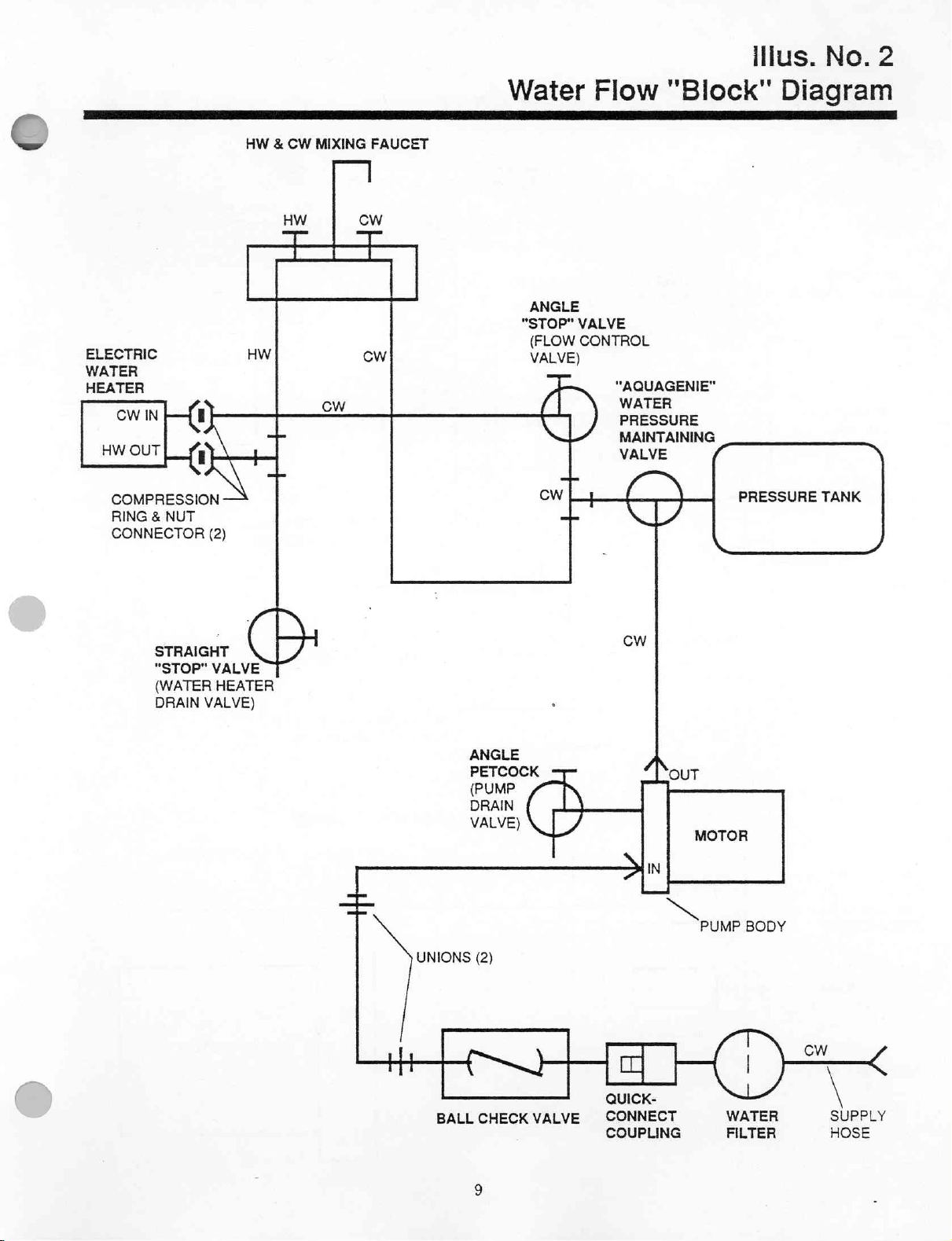
Illus.
No.
2
ELECTRIC
WATER
HEATER
CW
O
COMPRESSION
RING 8 NUT
CONNECTOR
IN
а
N
(2)
HW & CW
HW
二
HW
+
MIXING
一
CW
FAUCET
cw
==
cw
Water
ANGLE
"STOP"
(FLOW
VALVE)
U
cw
4
Flow
VALVE
CONTROL
"AQUAGENIE"
WATER
PRESSURE
MAINTAINING
VALVE
ÓN
NÜ
"Block"
PRESSURE
Diagram
TANK
STRAIGHT
"STOP"
(WATER
DRAIN
(|
VALVE
HEATER
VALVE)
-
|
UNIONS
li
TTT
OR]
BALL
ANGLE
PETCOCK
(РУМР
DRAIN
VALVE)
(2)
CHECK
、
L
VALVE
CW
Лол
Sin
m
QUICK-
CONNECT
COUPLING
MOTOR
PUMP
ST
y
WATER
FILTER
BODY
CW
SUPPLY
HOSE
/
>
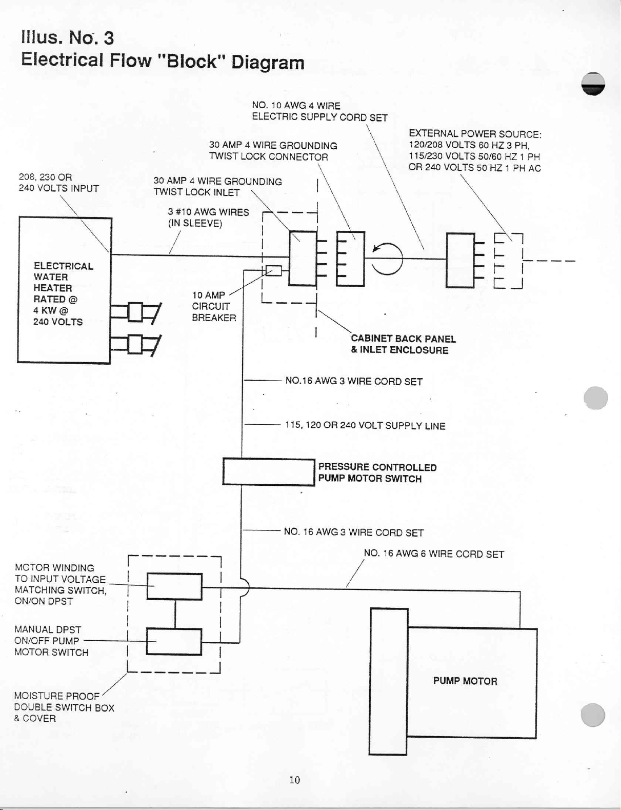
Illus.
No.
3
Electrical
208,
230
OR
240
VOLTS
INPUT
κ
X
ELECTRICAL
WATER
HEATER
re
240
VOLTS
Fiow
"Block"
30
TWIST
30
AMP
4
WIRE
TWIST
LOCK
3410
AWG
(IN
SLEEVE)
/
10
AMP
cIRcur | 上
RES
Diagram
NO.
ELECTRIC
AMP
4
WIRE
LOCK
GROUNDING
INLET
WIRES
S
|
TL
|
10
AWG 4 WIRE
SUPPLY
GROUNDING
CONNECTOR
|
|>
===
一 一 一
|
CORD
rE
TE
SET
ビバ
A
CABINET
&
INLET
BACK
ENCLOSURE
EXTERNAL
120/208
115/230
OR
VOLTS
VOLTS
240
VOLTS
PANEL
POWER
60
50/60
50
№
Lon
PE
Cr
SOURCE:
HZ
3
PH,
HZ
1
HZ 1 PH
L___
|
EJ
PH
AC
MOTOR
TO
MATCHING
ON/ON
MANUAL
ON/OFF
MOTOR
MOISTURE
DOUBLE
&
WINDING
INPUT
DPST
DPST
PUMP
SWITCH
SWITCH
COVER
VOLTAGE.
SWITCH,
PROOF
ノー
BOX
Mera
iel.
Г
|
Γ
|
|
| |
|
|
Yİ
a
一
ー
一
一
一
No.16AwG
—
LS
「
7
|
|
|
115,
No.
3
120
OR
240
PRESSURE
PUMP
16
AWG
3
WIRE
CORD
VOLT
SUPPLY
CONTROLLED
MOTOR
WIRE
SWITCH
CORD
NO.
16
SET
SET
AWG
LINE
6
WIRE
PUMP
CORD
MOTOR
SET
10
S
VERTE
1.
Wiring
current
the
or
fuse
within
carrying
is
required
P
SS
cabinet
at
designed
is
wires.
the
control
The
Patient
use
to
extension
panel.
independent
an
and
cord
Safety
ground
connectors
lead
are
and
which
at
rated
Other
V E
directly
not
is
30
Amps.
A
Precautions
SO
E
T
connected
Amp
30
to
circuit
of
any
breaker
NOTE:
When
2.
procedures
to
Set
3.
supply
NOTE:
Should
4.
water
The
Before
5.
system
lose
from
When
6.
20
During
motor
noted
priming
in
re-prime
pump,
temperature
is
cord
temperature
If
temperature.
pressurized
a
supply
control
motor
servicing
pressure
gaskets.
union
old
the
servicing
P.S.!.
by
installation
burnout,
the
in
system,
water
manual.
repeat
hot
for
plugged
means
by
switch
water
relieved
is
If
heater.
pressure
tank
manufacturer.
unit,
of
prepare
installation
check
pump
The
procedure
as
water
cabinet
into
great,
too
is
supply
water
supply
water
of
be
must
and
tank,
be
water
take
heater,
replacement
a
circuit
the
motor
pump
manual.
water
for
requires
until
a
instructions
per
outlet.
either
to
40
of
hose.
"off".
electric
sure
system
heater
notice
breaker
running
for
supply
water
only
continuous
in
sure
Make
increase
P.S.I.
60
will
This
power
drained.
is
assembly
'
new
a
that
(power)
on
hookup.
lubrication
for
flow
of
manual.
faucet
flow
the
available,
be
preclude
disconnected
is
When
installed,
is
in
tank,
should
one
either
run
not
Do
and
water
comes
sure
Make
water
hot
rotate
or
rate
this
necessity
the
disconnecting
may
it
of
case
this
at
"off"
be
three
the
of
without
pump
not
must
out
of
breaker
circuit
fully
is
valve
rheostat
be
may
unit
of
turned
or
be
replacement,
off
water
necessary
prevent
To
time.
water.
run
is
supply
dry.
"on"
Follow
If
and
electric
be
faucet.
open.
counterclockwise
connected
pump
having
the
entrance
at
lines
to
normally
is
from
use
pump
systems
priming
necessary
is
it
electrical
to
directly
box,
union
to
motor
water
heater,
fittings
pre-charged
as
desired
this
run.
not
do
to
7.
ESS
II
1.
2.
servicing
When
parts
these
must
Pump
draining
Wipe
down
stainless
Scour
are
be
desired
is
TENTA
cabinet
pressure
unless
"live"
drained
use
by
exterior
counter
steel
switch,
twist-lock
prevent
to
antifreeze,
of
with
Re
top
not
do
freeze
mild
and
touch
connector
damage
a
use
type
disenfectant
assembly
sink
terminals
wire
back
at
cold
in
non-toxic
soap.
with
of
cabinet
of
climate
antifreeze
type
mild
current
has
areas,
disinfectant
type
carrying
disconnected.
been
not
when
instruction
per
as
switch,
If
in
an
the
of
alternate
manual.
components
use.
in
Equipment
IO
bathroom
cleaners.
as
to
Care
AB

Installation
and
Operation
A
SR
NS
SESS
da
>
Electric
208
208
(equipment)
230
Volt
ment)
240
an
Note:
independent
connected
The
30
panel.
Installation
1.
2.
Supply
60
Volt,
Outputs;
Volt
50/60
Volt,
Outputs;
ground
50
Volt.
independant
The
extension
circuit
Amp.
Remove
respective
External
from
carton
“A.
Faucet
install
“C"
with
Gooseneck
*B.
Moisten
and
down,
swiveled
Basket
*C.
“Drop”
Filter/Hose
"Di
Engage
in
potabie
end
Drain
“E.
Slide
located
hose
Electric
*F.
Important!!!
“OFF”
Engage
Requirements:
Phase,
3
Hz,
this
ground
wiring,
to
wire.
Hz.
shall
this
wire.
Phase
1
Hz.
(equipment)
within
(equipment)
any
of
the
and
cord
breaker
hardware
cartons.
connections
assemblies.
Handles
handle
on
R.H.
head
flat
''0''
insert
into
ciockwise.
by
hand.
Strainer
10
sink
Assembly
male
back
panel
water
of
hose
at
Assembly
Hose
end
one
back
in
suitable
to
Supply
at
this
female
with
‘’Y'',
wire
4
be
shall
with
Phase.
1
plus
wire
3
be
output:
the
ground
current
this
ground
cabinet.
lead
carrying
connectors
is
fuse
or
and
umbilical
Note:
unit:
to
L.H.
on
‘'H'’
stem
in
the
desired
screws
ring
connector
of
supply.
found
base
on
opening
until
outlet
opening.
cabinet.
Connect,
water
supply.
corrugated
of
of
panel
waste
Extension
Circuit
time.
connector
in
faucet
tight.
in
Route
cabinet.
receptacle
Cord
Breaker
of
120
both
independent
plus
120
both
independent
be
shall
wire.
designed
is
is
which
wires.
rated
are
required
accessories
faucet
in
of
female.
electric
at
indicates
*
stem
positions.
of
top
gooseneck
body.
Gooseneck
connector
hose
or
submerge.
on
hose
Route
area.
or
Set
(Power)
supply
Volt
Volt
wire
2
not
30
at
the
from
and
valve
with
Turn
can
to
nearby
trap
free
and
230
and
(equip-
plus
use
to
directly
Amps.
control
items
handle
Secure
stems.
water
base
be
located
free
outlet
of
end
should
into
cord
an
A
be
male
electrical
and
twist
free
end
nected
to
Should
the
existing
plug
installed
directly
Connections
plug.
Other
electric
Connections
inlet
clockwise
of
cord
into a matching
the
available
plug
and
receptacle
plug
or
the
to a convenient
below
styles
schematics
combination
to
Supply:
(equipment)
line;
the
“Common”
supply
=
208
supply:
blade
supply
wire)
parallel
¡.e.:
blade
along
(red
“X”
‘‘Round’’,
blade
brass,
The
‘‘W'’,
straight
brass,
line,
i.e.:
Volts
Volts.
to
domestic
round.
blade
ground;
(black
line;
The
to
the
opposite
120
Volts
Volts
across
to
foreign 2 wire
round,
blade
ground;
(black
line
and
the
the
with
to
wire)
i.8.:
line,
“Y'*
and
GR".
dent
straight
ply
to
parallel
Volt
Vy" = 120
Connections
Volts
“GR”.
(equipment)
brass,
Volt
(white
"X"
line,
220-240
Connections
“GR”.
(equipment)
brass,
supply
wire)
blade
supply
and
located
to
lock
power
shall
be
supply
power
apply
to
shall
be
on
page
(green
blade
ground:
(black
silver
supply
blade
Voltage
and
voltage
combination
(green
The
wire)
‘‘W’’,
‘‘common"’
side
across
''X"'
(green
the
‘‘Y'’,
wire)
‘'W'',
‘‘X'’,
‘‘common’’
Voltage
across
230-250
=
in
back
panel
in
place.
receptacle
source.
be
incompatible,
removed
wired
and a suitable
cord
can
control
NEMA
14-30P
in
7, 8 or
accordance
120 and
wire)
‘‘Y'’,
The
to
wire)
angle,
blade
line;
and
the
(red
wire)
across
across
wire)
to
‘'Y'’,
adjacent
to
one
side
silver
angle,
supply
of
220-240
**W''
and
and
YY”.
240
Volts
wire)
to
adjacent
to
‘‘Hot'’
side
silver
angle,
parallel
straight
side
“W'
Volts.
of
cabinet
Insert
plug
con-
then,
be
connected
panel.
style
9.
Volt
208
indepen-
to
adjacent
Volt
208
a
(white
wire)
X,
to a 208
‘'W''
and
"X" 8 У”
120
and
240
independent
straight
of
220-240
blade
line;
and
Volt
supply
‘‘Y'',
and
supply:
independent
straight
of
240
blade
(white
brass,
Volt
240
of
“Y”
and
on
with
sup-
;
the
Volt
12
*G.
Casters,
Insert
bottom
rear.
Casters
stored
.
Important!!!
Prepare
three
A.
pump
electric
Open
located
Take
side
of
Lift
cover
and
snap
ΜΗ’).
Lift
cover
and
snap
voltage''
matches
i.e.;
toggle
120/208
and
toggle
230-250
if
needed
stems
of
cabinet,
inside
To
motor
supply
door
(doors)
at
inside
notice
switch
on
toggle
on
toggle
listing
the
V.
**Down””
V. 2 wire
of
casters
two
can
be
cabinet
Prevent
for
systems
front
of
“switch
box.
front
(L.H.)
down
rear
(R.H.)
either
on
external
‘‘up'’
(115V.
or
115/230
in
socket
at
the
front
removed
in
running
of
cabinet
the
power
without
rack
provided
Pump
on
as
noted
and
of
L.H.
function"
‘‘motor
to
‘‘Off’’
‘‘motor
up
or
down
‘‘switch
source
motor
V.
input
(230
V.
motor
input “line
plates
attached
and
two
at
tools
and
when
Motor
Burn-out.
either
one
of
below.
find
switch
end.
plate
on
“front”
control‘
(if
winding’
toward
function’’
winding)
“line
switch
not
already
“line
plate
characteristics,
For
voltage
winding)
voltage”...
to
the
can
not
in
the
box
switch
that
For
be
use.
G.
H.
J.
К.
Note:
M.
Turn
“On”
switch
and
water
comes
Close
cold
run
until
pressure
off”,
Note:
If it
operations
tinuous
Turn
cord
Open
Open
outlet,
water
out
valve.
Leave
Turn
cord
Do
flow
circuit
from
faucet
Fiew
enough
heater.
of
the
faucet spout,
Flow
circuit
to
cabinet
Not
Run
circuit
breaker
let
pump
run
out
of
the
water
faucet
is
built-up
is
necessary
'*A”'
through
of
water
comes
breaker
cabinet.
‘*HOT"'
Control
to
‘‘Off’’
water
Valve,
allow
When a steady
Control
Pump
Valve
breaker
electric
Dry.
and
‘‘motor
until a continuous
faucet.
valve.
Pump
should
to
re-prime
'*G''
out
or
enough
to
pump,
above
until a con-
of
faucet.
disconnect
valve.
on
pressure
water
to
flow
through
flow
of
water
close
faucet
‘‘HOT’’
“OPEN”.
‘‘On’’
or
reconnect
inlet.
control"
flow
of
now
shut
itself
repeat
power
tank
the
comes
water
power
Close
put
Use
“Dn”
.
Priming
pump
Note:
assembly
A
Open
switch
Close
body
Öpen
to
and
Open
and
body.
Close
Be
ply
cover
and
“line
voltage"
“motor
or
“Off”
of
Water
without
All
of
the
must
door
water.
above
be
(doors)
‘‘Off’’.
drain
valve
and
flow
“GOLD”
relieve
any
leave
open.
ball
valve,
pour 1 quart
ball
priming
sure
water
of
potable
do
not
is
control"
when
System.
external
made
before
of
on
water
control
water
pressure
located
of
water
valve.
supply
water.
disturb
changed.
switch
for
necessary.
Important:
connections
priming.
cabinet
and
heater,
valve
at
valve
of
that
may
vertically
through
hose
is
pressure
deck
routed
this
switch
turning
Do
turn
petcock
mounted
be
in
on
pump
valve
to a good
pump
not
run
and
motor
tank
the
system
into
unless
motor
control
on
pump
outlet.
faucet
body,
pump
sup-
in
5.
Hot
Water
Water
temperature
the
water
ing
through
approximately
the
heater
desirable
performance
A.
Check
electric
Pump
built-up
(Approximately
B.
Insert
into
slot
the
Open
Close
then
“window”
This
operate
imum
Temperature
heater
housing,
the
heater,
1/2
is
required
to
adjust
when
and
be
supply
switch
should
to
approximately
tip
of
small
hole
in
water
in
Rheostat
Rheostat.
faucet
‘‘HOT’’
flow
control
slowly
open
in
the
is
now
the
the
heater,
water
temperature
Adjustment
can
be
or
gallon
of
to
make
the
water
setting
sure
circuit
cord
is
be
45
P.S.1. @ 50
flat
heater
shaft:
water
valve
valve
face
lowest
and
controlled
varying
both. A minimum
water
heater
up the
plugged
**On””
blade
cover
turn
on
until
of
rate
this
by a Rheostat
the
per
the
heater
for
sink
breaker
into
and
60
P.S.!.
Hz.).
screwdriver
and
clockwise
vaive
fully.
pressure
light
appears
the
water
of
water
will
give
rate
minute
optimum
unit.
is
cabinet
water
on
engage
tank
heater
flow
rise.
of
water
flow
rate
through
function.
‘‘On’’
and
inlet.
pressure
gauge
carefully
blade
to
the
limit
outlet
in
the
cover.
needed
you
the
max-
in
flow-
of
It
is
in
of
and
to
FRS
E.
F.
6.
Soap
Control.
A.
B.
C.
7.
Draining
Freezing
A.
A1.
B.
RER
To
adjust
insert
screwdriver
the
CP
heater
counterclockwise
to
“pulse”.
stabilize
Note:
water
rate
rotate
water
Conversely,
creased,
operations.
rate
must
Shut
operational.
Dispenser,
Feed
located
in
front
Attach
penser
carton
To
fill
wrench
screw,
screw
dispenser
opening
The
at
this
Should
be
by
too
means
the
great.
Rheostat
temperature
the
within
Remember
of
approximately
be
maintained
off
faucet
clear
plastic
inside
cabinet
left
hand
loose
end
tubing
to
assembly.
soap
dispenser.
from
carton
located
enough
Water
body.
and
reinstall
to
System.
of
"HOT"
Filling
in
Climates.
Slip
one
end
of
tubing
petcock
of
located
same
container
over
on
clear
plastic
on
manner
Disengage
connector
water
out
Route
clear
tube
pump
tubing
the
water
as
filter/hose
in
back
of
filter
plastic
of at
least 1 gallon
RP
for
in
Rheostat
until
temperature
RS
optimum
light
in
should
siot
heater
setting.
temperature
either
the
flow
of
increase
control
counterclockwise
is
reached.
temperature
limits,
by
can
reversal
though, a water
1/2
gallon
if
heater
water
tubing
through
edge
of
of
clear
*rubber
assembly
dispenser
allow
Fill
with
dispenser
one
*18
projecting
body.
to
heater
and
Connecting
from
cabinet
plastic
"foot
engage
"head"
head
soap
For
Storage
inch
out
Apply
drainage
outlet
is
to
valve.
soap
rubber
pump"
*"Allen"
into
to
be
through
head.
long
of
second
above.
assembly
panel
of
cabinet
and
hose.
tubes
to
suitable
capacity.
PN
performance,
and
rotate
just
starts
now
the
"HOT"
the
flow
valve,
or
until
desired
be
in-
of
the
above
flow
per
minute
function.
Unit
is
now
Foot
dispenser
grommet
bottom.
soap
dis-
from
socket
socket
lifted
and
head
loosen
off
of
top
in
clear
plastic
brass
length
valve
piping
in
the
from
female
and
empty
waste
A
C.
Shut
nect
circuit
D.
Open
the
E.
Leave
F.
After
gauge,
water
water
G.
Close
water
H.
Open
allows
out
1.
Close
"motor
electric
water
the
through
control"
supply
breaker
faucet
and
faucet
pressure
open
heater
out
of
system
Petcock
valve.
faucet
water
heater
faucet
valves.
J.
8.
Preparing
Reverse
Water
system
-water
cold
been
system,
water
"seal"
system
now
priming.
system
and can
shipping.
Note:
To
with
supply
water
replaced
close
supply
the
filled
be
set-up
Unit
of
Operation
now
prepare
non-toxic
faucet
antifreeze
(Operation
"G"
General
Should a pressurized
be
this
hose.
pump
be
current
Note:
available,
water
This
motor
"OFF".
this
supply
will
run.
This
consumption
unit
by
preciude
The
will
ate.
K
switch
extension
"Off"
"Off").
Cold
Water
pressure
Cold
has
petcock
outlet
on
HOT
water
in
faucet
hot
water
should
be
prepared
unit
hose,
valves.
by
antifreeze,
faucet
hose
at
with
for
For
Storage
No.
water
may
means
the
Motor
save
approximately 8 Amps.
and
the
Valve
in
the
Water
and
pump
drain
pump,
Valve
dropped
on
pump
drain
and
pump.
and
valve
hot
water
valve.
and
heater
now
be
for
for
storage.
antifreeze
and
After
valves,
cabinet
in
the
system.
and
antifreeze,
use
at
any
No.
3).
or
2.
Steps
supply
be
connected
of
the
water
necessity
Control
system
O
and
discon-
cord
(or
turn
to
discharge
water
system.
"OPEN".
to
zero
on
the
and
valve
on
remainder
faucet
which
riser
drained
storage
through
the
clear
COLD
now
to
drain
of
or,
Purge
hot
and
water
of
drain
water
the
the
has
de-pressurize
disconnect
back.
This
will
With
the
the
unit
can
time
without
Shipping.
"A"
through
of
40
to
60
P.S.I.
directly
to
supply
of
having
Switch
the
must
in
will
still
oper-
~
14

Storage
Requirements
Recommended
Temperature
Humidity
Limits:
Periodic
1.
WATER
2.
WATER
3.
WASTE
4.
SOFT-FLO
GOOSENECK
5.
WATER
6.
INTERIOR
7.
SINK
BOWL/TOP
Long
(Store
Term
within a sheltered
Storage
Limits: 0 Degree
Minimum
Maximum
Maintenance
FILTER
SUPPLY
OUTLET
LEAKS
OF
HOSE
HOSE
NOZZLE
CABINET
Storage
ON
and
area
Climate
Fahrenheit — +130
Schedule:
FAUCET
Maintenance
at
moderate
Limits
Humidity-5%
Humidity-95%
(While
AND
humidity
Degree
unit
is
in
use)
Inspect
and
clean
restricted.
Deterioration
repair
as
necessary.
Deterioration
repair
as
necessary.
Remove
and
restricted.
Check
components
Clean
Clean
daily:
tighten
as
weekly.
as
deemed
Schedule:
and
temperature
Fahrenheit
monthly
and/or
and/or
clean
damage.
damage.
monthly
joint
received.
necessary
levels)
or
sooner,
Monthly
Monthly
or
sooner
fittings
and/or
to
maintain
should
water
flow
be
inspection - replace
inspection - replace
should
water
replace
sanitary
flow
defective
conditions.
or
or
be
1.
WATER
2.
WASTE
3.
ELECTRICAL
4.
CASTER
5.
ELECTRICAL
SUPPLY
OUTLET
WHEELS
CONNECTOR
6.
INTERNAL
WATER
7.
MISSING
8.
PUMP
9.
MOTOR
10.
CABINET - DAMAGE
PIPING
PARTS
MOTOR
BEARINGS
HOSE
HOSE
UMBILICAL
INLET
AND
ELECTRICAL
AND/OR
SHAFT
ASSEMBLY
(EXTENSION
WATER
CORDS
ACCESSORIES
OR
RUSTING
QUICK
AND
Deterioration and/or
repair
as
required.
Deterioration
repair
as
Deterioration
repair
CORD)
Free
wheeling.
Corrosion
repair
as
Deterioration
defective
Resupply
Accessory
Rotate
Yearly
Permanently
years
of
Yearly
rust
and
and/or
required.
and/or
as
required.
Yearly
and/or
obstructions. Yearly
required.
and/or
components.
as
necessary.
List.
Yearly
manually
to
inspection.
lubricated - inspect
storage.
Replace
inspection - Repair
"Touch
Up
damage.
damage.
damage.
inspection.
damage.
See
inspection.
prevent
bearings
minor
Paint".
Yearly
Yearly
Yearly
Yearly
pages
seizure
for
damage
inspection - replace
inspection - replace
inspection - replace
Lightly
oil
or
inspection.
inspection.
20,21,22
at
bearings
"DRY"
or
bearings,
motor.
and/or
grease
Replace
Replace
and
or
remove
23
pump
for
after
or
or
or
bearings.
or
Parts/
seal.
5
15