

Page 1
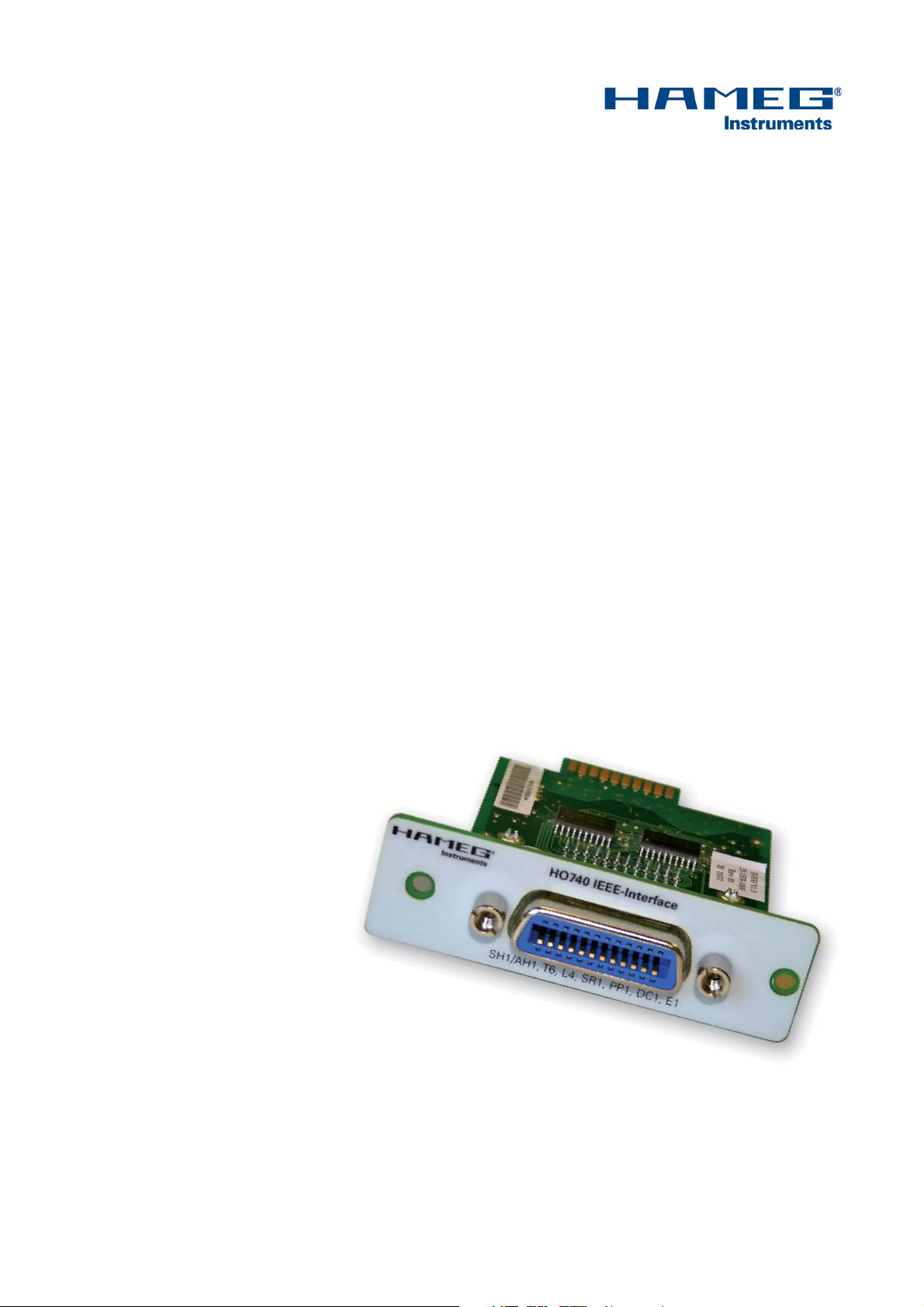
IEEE-488 (GBIP)
INTERFACE
HO740
Fitting Instruction
English
Page 2
General information regarding the CE marking
General information regarding the CE marking
HAMEG instruments fulfi ll the regulations of the EMC directive. The
conformity test made by HAMEG is based on the actual generic- and
product standards. In cases where different limit values are applicable,
KONFORMITÄTSERKLÄRUNG
DECLARATION OF CONFORMITY
DECLARATION DE CONFORMITE
DECLARACIÓN DE CONFORMIDAD
Hersteller / Manufacturer / Fabricant / Fabricante:
HAMEG Instruments GmbH · Industriestraße 6 · D -63533 Mainhausen
Die HAMEG Instruments GmbH bescheinigt die Konformität für das Produk t
The HAMEG Instruments GmbH herewith declares conformity of the product
HAMEG Instruments GmbH déclare la conformite du produit
HAMEG Instruments GmbH certifi ca la conformidad para el producto
Bezeichnung: IEEE-488 Interface
Product name: IEEE- 488 Interface
Designation: Interface IEEE-488
Descripción: Interfaz IEEE-488
Typ / Type / Type / Tipo: HO740
mit / with / avec / con: HM1008, HM1508, HM1508-2, HM2008
Optionen / Options /
Options / Opciónes: –
mit den folgenden Bestimmungen / with applicable regulations /
avec les directives suivantes / con las siguientes directivas:
EMV Richtlinie 89/ 336/EWG ergänzt durch 91/263 /EWG, 92 /31/EWG
EMC Directive 89/ 336/EEC amended by 91/263/ EWG, 92/ 31/EEC
Directive EMC 89/ 336/CEE amendée par 91/263/EWG, 92/31/ CEE
Directiva EMC 89/ 336/CEE enmendada por 91/263 /CEE, 92 /31/CEE
Niederspannungsrichtlinie 73/23 /EWG ergänzt durch 93/68 /EWG
Low-Voltage Equipment Directive 73/23 /EEC amended by 93 /68/ EEC
Directive des equipements basse tension 73 /23/ CEE amendée par 93/68/CEE
Directiva de equipos de baja tensión 73 /23/ CEE enmendada por 93 /68/ EWG
Angewendete harmonisierte Normen / Harmonized standards applied /
Normes harmonisées utilisées / Normas armonizadas utilizadas:
HAMEG applies the severer standard. For emission the limits for
residential, commercial and light industry are applied. Regarding the
immunity (susceptibility) the limits for industrial environment have
been used.
The measuring- and data lines of the instrument have much infl uence
on emmission and immunity and therefore on meeting the acceptance
limits. For different applications the lines and/or cables used may
be different. For measurement operation the following hints and
conditions regarding emission and immunity should be observed:
1. Data cables
For the connection between instruments resp. their interfaces and
external devices, (computer, printer etc.) suffi ciently screened cables
must be used. Without a special instruction in the manual for a reduced
cable length, the maximum cable length of a dataline must be less than
3 meters and not be used outside buildings. If an interface has several
connectors only one connector must have a connection to a cable.
Basically interconnections must have a double screening. For IEEE-bus
purposes the double screened cables HZ73 and HZ72L from HAMEG
are suitable.
2. Signal cables
Basically test leads for signal interconnection between test point and
instrument should be as short as possible. Without instruction in the
manual for a shorter length, signal lines must be less than 3 meters
and not be used outside buildings.
Signal lines must screened (coaxial cable - RG58/U). A proper ground
connection is required. In combination with signal generators double
screened cables (RG223/U, RG214/U) must be used.
Sicherheit / Safety / Sécurité / Seguridad:
EN 61010-1: 2001 / IEC (CEI) 1010-1:20 01
Überspannungskategorie / Overvoltage category / Catégorie de surtension /
Categoría de sobretensión: II
Verschmutzungsgrad / Degree of pollution / Degré de pollution / Nivel de
polución: 2
Elektromagnetische Verträglichkeit / Electromagnetic compatibility /
Compatibilité électromagnétique / Compatibilidad electromagnética:
EN 61326 -1/A1: Störaussendung / Radiation / Emission: Tabelle / table /
tableau 4; Klasse / Class / Classe / classe B.
Störfestigkeit / Immunity / Imunitee / inmunidad:
Tabelle / table / tableau / tabla A1.
EN 61000-3 -2/A14: Oberschwingungsströme / Harmonic current emissions
/ Émissions de courant harmonique / emisión de corrientes armónicas:
Klasse / Class / Classe / clase D.
EN 61000-3 -3: Spannungsschwankungen u. Flicker / Voltage fl uctuations
and fl icker / Fluctuations de tension et du fl icker / fl uctuaciones de tensión
y fl icker.
Datum / Date / Date / Fecha
26. 04. 2007
Unterschrift / Signature / Signatur / Signatura
3. Infl uence on measuring instruments.
Under the presence of strong high frequency electric or magnetic fi elds,
even with careful setup of the measuring equipment an infl uence of
such signals is unavoidable.
This will not cause damage or put the instrument out of operation. Small
deviations of the measuring value (reading) exceeding the instruments
specifi cations may result from such conditions in individual cases.
HAMEG Instruments GmbH
Holger Asmussen
Manager
2
Änderungen vorbehalten
Page 3

Content
Declaration of conformity 2
General information regarding the CE marking 2
2. Safety hints 4
3. Interface Description 4
4. Oscilloscope Firmware 4
5. Interface Fitting Instruction 5
6. Functions and settings 6
7. Appliance 7
Änderungen vorbehalten
3
Page 4

General hints
2. Safety hints
Attention!
Fitting or exchanging of an interface must not be
made unless the oscilloscope is switched off and
not connected to line (mains).
Attention!
During operation the interface opening must be
closed.
Attention!
All interface connections are galvanically isolated
from the scope to avoid so called “hum” loops by
multiple earthing (in this case by the PC).
Measurement at high potentials is prohibited. It
would endanger scope and operator.
If the safety rules are disregarded any damage to HAMEG Instruments GmbH products will void the warranty. Neither will
HAMEG Instruments GmbH take any responsibility for damage
to people or gear of other make.
4. Oscilloscope Firmware
4.1 It is absolutely necessary to check the oscilloscope
fi rmware version before fi tting the Interface HO740. The
fi rmware version already on the scope is displayed after
s w i t c h i n g o n i f “ Q u i c k S t a r t ” i s o f f . T h e “ Q u i c k S t a r t ” f u n c t i o n
can be changed after pressing the SETTINGS pushbutton
and calling “Misc.”.
4.2 If the fi rmware version is 0 5.105-yy.yy y or higher, continue
the inter face fi t ting as des cribed und er item 5 (HO740 Fit ting
Instruc tion). In case fi rmware versions below 05.105-yy.yy y,
HO740 will not be recognised and a fi rmware update is
required as described under item 4.3.
4.3 In case of a fi rmware version below 05.105-yy.yyy, please
download the cur rent fi rmware at www.hameg.com from
the Internet and actualise the oscilloscope. The fi rmware
can be found and download under: Products > Oscilloscopes > (oscilloscope type) > Software/Firmware (below
the oscilloscope picture) > Firmware_HMxxx_Vxxx.zip.
After receiving the current fi rmware and its installation instruction, the fi rmware installation must be done via the present
interface (HO710, HO720 or HO730).
3. Interface Description
HO740 is an IEEE-488.2 (GPIB) Interface enabling the integration
of the oscilloscopes HM1008, HM1508 and HM2008 in automatic
test systems. The interface has an IEEE-488 socket, in which
an IEEE-488 cable can be inserted.
HO740 is a device that receives commands from a controller,
delivers them to the scope and if required transmits signal data
to the controller.
4
Änderungen vorbehalten
Page 5

Fitting Instruction
5. Interface Fitting Instruction
Safety!
The following procedures must only be carried out on condition that the mains (line) power cable is not connected to the
oscilloscope and no connection is made at the measurement
inputs.
Attention!
To avoid damage of the interface during removing
and fi tting by electrostatic discharge, please touch
a metal part of the oscilloscope for potential equalisation between oscilloscope and your body. Abide
this connection during the fi tting/removing!
Only handle the interface by its IEEE-488 socket!!
5.1 Removing of the actually inserted interface.
5.2 Fitting the interface HO740
5.2.1 Insert the interface HO740
in the opening in such a way, that
the PCB will be inserted in the
guidance - visible on both sides – and push it in completely.
5.1.1 Remove both fastening screws
5.1.2 Pull out the interface.
5.2.2 Fit the interface with the previously (item 5.1.1) removed
fastening screws.
Änderungen vorbehalten
5
Page 6

Functions and settings
6. Functions and settings
6.1 Flow control (SH1, AH1)
The fl ow control is for both transmitter and receiver (SH – Source Handshake / AH – Acceptor Handshake) is required for all
further functions incl. the transmission of bus specifi c control
data and therefore supported. Extended fl ow control with the
possibility of a simplifi ed indication is not implemented.
6.2 Transmission and reception of data (T6, L4)
The instrument is able to transmit and receive data if the corresponding function (T – Talker / L – Listener) has been activated
by the control device. For addressing of both functions the same
primary basic address has to be used. Secondary addresses
are not supported.
“Talk Only” and “Listen Only” modes cannot be activated.
6.3 State information (SR1, PP1)
Interface state information can be polled in sequential mode
(Serial Poll) as well as simultaneously from several devices
(PP – Parallel Poll) from the bus. All required interface settings for parallel polling are made by the control device via the
IEEE488-Bus.
6.6 Bus driver (E1)
The IEEE-488 bus data and control lines are controlled by drivers with open collector outputs. As to be seen in IEEE-488.1
standard, this enables a data rate of up to 250000 Bytes per
second.
6.7 Addressing of IEEE-488 devices
The IEEE-488 standard specifi es the address structure for
transmitter and receiver functions of a device. It allows you to
assign separate addresses for different device functions such
as transmission and receiving functions or for several different
transmission and receiving functions as appropriate.
These addresses can consist of a primary and a secondary part.
Both have a variable part (5 bit) for the real address and a fi xed
group allocation (2 bit). The 8th bit is not used.
Thus instrument addresses in the range from 0 to 30 (00h to
1Eh) are available. The address 31 (1Fh) has a special function.
It is used to deactivate the function of an addressed group on
the bus (UNL – Unlisten / UNT – Untalk).
The following address groups are specifi ed:
Primary addresses for receiver function (coding: 20h)
Primary addresses for transmitter function (coding: 40h)
Secondary addresses (coding: 60h).
E.g. the complete primary address of the receiver function of a
device with the basic address 8 will be 40 (28h).
If the confi guration of the device enable register is applicable
(note SCPI programming commands) the interface indicates the
control device internal state changes (SR – Service Request).
This avoids waiting time for the instrument’s reply or the recurrent query for the instrument state. The required device settings
must be made each time the device is switched on.
6.4 Communication initialisation (DC1)
Bus specific control commands “DCL” (Device Clear) and
„SDC“ (Selected Device Clear) will be processed by the internal
management, independent of other SCPI commands still to be
processed (DC – Device Clear). Within the instrument the SCPI
command processing will be newly initiated, the execution of
current commands will be interrupted, and the data buffer will
be deleted. The fl ow control cannot indicate the acceptance for
new data transmission until these data have been completely
processed.
6.5 Not supported functions (RL0, DT0, C0, CF0)
The following functions are not supported:
Switch over between local and remote with the opportunity to
lock local controls (RL – Remote Local)
External start of the instruments basic functions (DT – Device
Trigger)
Bus controller operation (C – Controller)
Considering the control device IEEE-488 bus cable length (CF
– Confi guration)
6.8 Selection of Primary Address
The selection of an address is only possible if, as described
under item 4 (Oscilloscope Firmware) a fi rmware version
05.105-yy.yyy or higher is present in the scope and the interface
HO740 is fi tted.
Pressing the SETTINGS pushbutton calls the “Settings” menu.
The function key “Interface” opens the submenu “Settings
Interface” causing “IEEE-488” and highlight “Address x” to be
displayed. The address (x) can be changed between 0 and 30 by
turning the INTENS knob. Please note that the selected address
must not used by any other instrument on the bus.
Local controls can be locked by SCPI commands (note SCPI
programming commands).
6
Änderungen vorbehalten
Page 7

7. Appliance
The SCPI programming commands list will be provided in the
Internet under www.hameg.com: Service&Support > Downloads > Software/Firmware: Software Commands for Oscilloscopes HM1008, HM1508 and HM2008.
Mainhausen, Germany
May 2007
Appliance
Änderungen vorbehalten
7
Page 8

Oscilloscopes
Spectrum Analyzer
Power Supplies
Modular System
8000 Series
Programmable Instruments
8100 Series
authorized dealer
www.hameg.com
Subject to change without notice
21-05-2007-gw HAMEG Instruments GmbH
© HAMEG Instruments GmbH Industriestraße 6
A Rohde & Schwarz Company D-63533 Mainhausen
® registered trademark Tel +49 (0) 61 82 800-0
DQS-Certifi cation: DIN EN ISO 9001:2000 Fax +49 (0) 61 82 800-100
Reg.-Nr.: 071040 QM sales@hameg.de
 Loading...