

Page 1
350 MHz
Digital Oscilloscope
with FFT and mixed-signal (option)
HMO3522/3524
Manual
English
Page 2
General information regarding the CE marking
KONFORMITÄTSERKLÄRUNG
DECLARATION OF CONFORMITY
DECLARATION DE CONFORMITE
Hersteller HAMEG Instruments GmbH
Manufacturer Industriestraße 6
Fabricant D-63533 Mainhausen
General information regarding the CE marking
HAMEG instruments fulfi ll the re gulations of t he EMC direc tive. The conf ormity
te st ma de b y H AM EG i s b as ed o n t he a ct ua l g ene ri c- and pr od uc t st an da rd s. In
cases where different limit values are applicable, HAMEG applies the severer
stan dard. For emis sion the limit s for reside ntial, commer cial and light i ndustry
are applied. Regarding the immunity (susceptibility) the limits for industrial
environment have been used.
The measuring- and data lines of the instrument have much infl uence on
emission and immunity and therefore on meeting the acceptance limits.
For different applications the lines and/or cables used may be different. For
measurement operation the following hints an d conditions r egarding emi ssion
and immunity should be observed:
Die HAMEG Instruments GmbH bescheinigt die Konformität für das Produkt
The HAMEG Instruments GmbH declares conformity of the product
HAMEG Instruments GmbH déclare la conformite du produit
Bezeichnung: Oszilloskop
Product name: Oscilloscope
Designation: Oscilloscope
Typ / Type / Type: HMO3524
mit / with / avec: HO720
Optionen / Options / Options: HO730, HO740
mit den folgenden Bestimmungen / with applicable regulations / avec les
directives suivantes
EMV Richtlinie 89/336/EWG ergänzt durch 91/263/EWG, 92/31/EWG
EMC Directive 89/336/EEC amended by 91/263/EWG, 92/31/EEC
Directive EMC 89/336/CEE amendée par 91/263/EWG, 92/31/CEE
Niederspannungsrichtlinie 73/23/EWG ergänzt durch 93/68/EWG
Low-Voltage Equipment Directive 73/23/EEC amended by 93/68/EEC
Directive des equipements basse tension 73/23/CEE amendée par
93/68/CEE
Angewendete harmonisierte Normen / Harmonized standards applied
Normes harmonisées utilisées:
Sicherheit / Safety / Sécurité:
EN 61010-1:2001 (IEC 61010-1:2001)
1. Data cables
For the connection between instrument interfaces and external devices,
(computer, printer etc.) suffi ciently screened cables must be used. Without
a special instruction in the manual for a reduced cable length, the maximum
cable length of a dataline must be less than 3 meters and not be used outside
buildi ngs. If an inter face has se veral conne ctors only on e connector mu st have
a connection to a cable.
Basically interconnections must have a double screening. For IEEE-bus
purposes the double screened cable HZ72 from HAMEG is suitable.
2. Signal cables
Basically test leads for signal interconnection between test point and
instrument should be as short as possible. Without instruction in the manual
for a shorter length, signal lines must be less than 3 meters and not be used
outside buildings.
Signal lines must screened (coaxial cable - RG58/U). A proper ground
connection is required. In combination with signal generators double screened
cables (RG223/U, RG214/U) must be used.
3. Infl uence on measuring instruments
Under the presence of strong high frequency electric or magnetic fi elds, even
with careful setup of the measuring equipment, infl uence of such signals is
unavoidable.
This will not cause damage or put the instrument out of operation. Small
deviations of the measuring value (reading) exceeding the instruments
specifi cations may result from such conditions in individual cases.
Messkategorie / Measuring category / Catégorie de mesure: I
Überspannungskategorie / Overvoltage category /
Catégorie de surtension: II
Verschmutzungsgrad / Degree of pollution / Degré de pollution: 2
Elektromagnetische Verträglichkeit / Electromagnetic compatibility /
Compatibilité électromagnétique
EN 61326-1/A1 Störaussendung / Radiation / Emission:
Tabelle / table / tableau 4; Klasse / Class / Classe B.
Störfestigkeit / Immunity / Imunitée: Tabelle / table / tableau A1.
EN 61000-3-2/A14 Oberschwingungsströme / Harmonic current emissions
Émissions de courant harmonique: Klasse / Class / Classe D.
EN 61000-3-3 Spannungsschwankungen u. Flicker / Voltage fl uctuations
and fl icker / Fluctuations de tension et du fl icker.
Datum / Date / Date
01. 03. 2009
Unterschrift / Signature / Signatur
Holger Asmussen
Manager
4. RF immunity of oscilloscopes.
4.1 Electromagnetic RF fi eld
The infl uence of electric and magnetic RF fi elds may become visible (e.g. RF
superimposed), if the fi eld intensity is high. In most cases the coupling into
the oscilloscope takes place via the device under test, mains/line supply, test
leads, control cables and/or radiation. The device under test as well as the
oscilloscope may be effected by such fi elds.
Although the interior of the oscilloscope is screened by the cabinet, direct
radiation can occur via the CRT gap. As the bandwidth of each amplifi er stage
is higher than the total –3dB bandwidth of the oscilloscope, the infl uence of RF
fi elds of even higher frequencies may be noticeable.
4.2 Electrical fast transients / electrostatic discharge
Electrical fast transient signals (burst) may be coupled into the oscilloscope
directly via the mains/line supply, or indirectly via test leads and/or control
cables. Due to the high trigger and input sensitivity of the oscilloscopes, such
normally high signals may effect the trigger unit and/or may become visible
on the TF T, which is unavoidable. These effects can also be caused by direct
or indirect electrostatic discharge.
HAMEG Instruments GmbH
2
Subject to change without notice
Page 3

Contents
General information regarding the CE marking 2
350 MHz Digital Oscilloscope HMO3522 / HMO3524 4
Specifi cations 5
1 Installation and safety instructions 6
1.1. Setting up the instrument 6
1.2. Safety 6
1.3. Correct operation 6
1.4. Ambient conditions 6
1.5. Warranty and repair 6
1.6. Maintenance 7
1.7. CAT I 7
1.8. Mains voltage 7
2 Familiarize yourself with your new HAMEG
Digital Storage Oscilloscope 8
2.1. Front view 8
2.2. Control panel 8
2.3. Screen 9
2.4. Rear view 9
2.5. Options 9
2.6. General concept of instrument operation 9
2.7. Basic setting and integrated help 10
2.8. Firmware- and help updates 11
3 A quick introduction 12
3.1. Setting up and turning the instrument on 12
3.2. Connection of a probe and signal capture 12
3.3. Display of signal details 12
3.4. Cursor measurements 13
3.5. Automatic measurements 13
3.6. Mathematical functions 14
3.7. Storing data 14
7 Display of signals 20
7.1. Display settings 20
7.2. Use of the virtual screen area 20
7.3. Signal intensity and persistence functions 21
7.4. XY display 21
8 Measurements 22
8.1. Cursor measurements 22
8.2. Auto measurements 23
8.3. Quickview measurements 24
9 Analysis 24
9.1. Quick mathematics 24
9.2. Formula editor 25
9.3. Frequency analysis (FFT) 26
10 Documentation, storing and recalling 27
10.1. Instrument settings 27
10.2. References 28
10.3. Curves 28
10.4. Screen shots 29
10.5. Sets of formulas 29
10.6. Defi nition of the FILE/PRINT key 29
11 Mixed Signal Operation (optional) 30
11.1. Logic trigger 30
11.2. Display functions of the logic channels 30
11.3. Cursor measurements for the logic channels 31
12 Appendix 32
4 Vertical system 15
4.1. Coupling 15
4.2. Sensitivity, Y-Positioning, and Offset 16
4.3. Bandwidth Limit and Signal Inversion 16
4.4. Probe attenuation selection 16
5 Horizontal System (Time Base) 17
5.1. Capturing modes RUN and STOP 17
5.2. Time base adjustments 17
5.3. Capture modes 17
5.4. ZOOM function 17
6 Trigger System 18
6.1. Trigger modes Auto, Normal, Single 18
6.2. Trigger sources 19
6.3. Slope trigger 19
6.4. Pulse trigger 19
6.5. Video trigger 20
Subject to change without notice
3
Page 4
HMO3524
4GSa /s Real time, 50GSa /s Random sampling,
low noise flash A/ D converter (reference class)
2MPts memory per channel, memory oom up to 100,000:1
MSO (Mixed Signal Opt. HO3508) with 8 /16 logic channels
Vertical sensitivity 1mV...5V/div. (into 1MΩ/50Ω)
Offset control ±0,2...±20V
12div. x-axis display range
Trigger modes: slope, video, pulsewidth, logic,
delayed, event
FFT for spectral analysis
6 digit counter, Autoset, automeasurement, formula editor
6.5” TFT VGA display, DVI output
3 x USB for mass storage, printer and remote ctrl.
optional IEEE-488 or Ethernet/USB
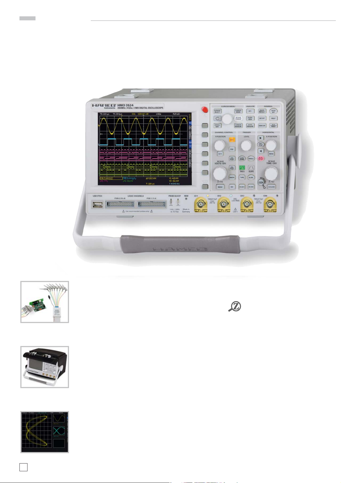
350MHz 2/4 Channel Digital Oscilloscope
HMO3522/HMO3524
HMO3524
NEW
The operating mode XYZ
Carrying Case HZ99
8 Channel
logic probe HO3508
4
Subject to change without notice
Page 5

350 MHz 2 [4] Channel Digital Oscilloscope
HMO3522 [HMO3524]
All data valid at 23 °C after 30 minute warm-up
Display
Display: 6,5” VGA Color TFT
Resolution: 640 x480 Pixel
Backlight: LED 400cd/m
2
Display area for curves:
without menu 400 x 600 Pixel (8x 12 div.)
with menu 400 x 500 Pixel (8x 10 div.)
Color depth: 256 colors
Intensity steps per channel: 0…31
Vertical System
Channels:
DSO mode CH1, CH2 [CH1...CH4]
MSO mode CH1, CH2 LCH 0...15 (logic channels)
with 2 x Option HO3508
Auxiliary input: Frontside [Rear side]
Function Ext. Trigger
Impedance 1MΩ || 13pF ± 2pF
Coupling DC, AC
Max. input voltage 100V (DC + peak AC)
XYZ-mode: All analog channels on individual choise
Invert: CH 1, CH 2 [CH1...CH4]
Y-bandwidth (-3dB): 350MHz (5 mV...5V)/ div.
100MHz (1mV, 2mV) / div.
Lower AC bandwidth: 2Hz
Bandwidth limiter
(switchable): approx. 20MHz
Rise time (calculated): ‹ 1ns
DC gain accuracy 2%
Input sensitivity: 12 calibrated steps
CH1, CH2 [CH1...CH4] 1mV/div.…5V/div. (1-2-5 Sequence)
Variable Between calibrated steps
Inputs CH1, CH2 [CH1…CH4]:
Impedance 1MΩ II 13pF ± 2pF (50Ω switchable)
Coupling DC, AC, GND
Max. input voltage 200V (DC + peak AC), 50Ω ‹ 5V
rms
Measuring circuits: Measuring Category I (CAT I)
Position range ± 10Divs
Offset control:
1mV, 2mV ±0,2V
5mV…50mV ±1V
100mV…5V ±20V
Logic channels With Option HO3508
Select. switching thresholds TTL, CMOS, ECL, 2 x User -2V…+8V
Impedance 100kΩ || ‹ 4pF
Coupling DC
Max. input voltage 40V (DC + peak AC)
Triggering
Analog channels:
Automatic: Linking of peakdetection and triggerlevel
Min. signal height 0.8 div; 0.5div typ.
Frequency range 5Hz…400MHz
Level control range From peak- to peak+
Normal (without peak):
Min. signal height 0.8 div; 0.5div typ.
Frequency range 0…400MHz
Level control range –10div....+10div.
Operating modes: Slope / Video/Logic/ Pulse
Slope: Rising, falling, both
Sources: CH1, CH2, Line, Ext., LCH0…15
[CH1...CH4, Line, Ext., LCH0…15]
Coupling: AC: 5Hz...400MHz
DC: 0...400MHz
HF: 30kHz...400MHz
LF: 0...5kHz
Noise rejection: 100MHz LPF switchable
Video: Pos. / neg. sync. impulse
Standards 525 Line / 60Hz systems
625 Line/50Hz systems
Fields Field 1, field 2, both
Line All, selectable line number
Source CH1, CH2, Ext. [CH1...CH4]
Logic: AND, OR, TRUE, FALSE
Source LCH0…15
State LCH0…15 X, H, L
Indicator for trigger action: LED
Ext. Trigger via: Auxiliary input [Aux. input at rear side]
0,3V…10V
ss
2nd Trigger:
Slope Rising, falling, both
Accessories supplied: Line cord, Operating manual, 2 [4] Probes, 10:1 with
attenuation ID (HZ350), Dual-Interface USB/RS-232 (HO720), CD
Optional accessories:
HO730 Dual-Interface Ethernet/USB
HO740 Interface IEEE-488 (GPIB) galvanically isolated
HZ46 4RU 19'' Rackmount Kit
HZ355 Slimline Probe 10:1 with automatically identification
HO3508 8 Channel Logic Probe
Min. signal height 0.8 div; 0.5div typ.
Frequency range 0…400MHz
Level control range –10div....+10div.
Operating modes:
after time 20ns…0.1s
after incidence 1…2
16
Horizontal System
Domain representation: Time, Frequency (FFT), Voltage (XY)
Representation Time Base: Main-window, main- and zoom-window
Memory Zoom: Up to 100.000:1
Accuracy: 15ppm
Time Base:
Refresh operating modes 1ns / div.…20ms / div.
Roll operating modes 50ms / div.…50s / div.
Digital Storage
Sampling rate (real time): 2x2GSa/s, 1x4GSa/s
[4 x 2GSa/s, 2 x 4GSa/s]
Logic channels: 16 x 1GSa/s
Sampling rate (random): 50GSa/s (n / a to logic channels)
Memory: 2 x 2MPts [4 x2MPts]
Operation modes: Refresh, Average, Envelope, Peak-Detect
Roll: free run/ triggered, Smooth
Resolution (vertical) 8Bit
Resolution (horizontal)
Yt Mode (50 Pts./div.)
XY Mode 8Bit
Interpolation: Sinx / x (CH1...CH4), Pulse (LCH0...15)
Persistence: Off, 50 ms...∞
Delay pretrigger: 0...2 Million x (1/samplerate)
posttrigger: 0...8 Million x (1/samplerate)
Display refresh rate: Up to 2500 waveforms/ s
Display: Dots, vectors (interpolation), ‘persistence’
Reference memories: typ. 10 Traces
Operation / Measuring / Interfaces
Operation: Menu-driven (multilingual), Autoset,
help functions (multilingual)
Save / Recall memories: typ. 10 complete instrument parameter
settings
Frequency counter:
0.5Hz...350MHz 6 Digit resolution
Accuracy 15ppm
Auto measurements: Frequency, Period, pulse count, UDC, Upp,
Up+, Up-, U
RMS
, U
Avg
, t
Rise
, t
Fall
Cursor measurements: ΔV, Δt, 1/Δt (f), V to Gnd, Vtrelated to Trigger
point, ratio X and Y, pulse count, peak to
peak, peak+, peak-
Interface: Dual-Schnittstelle USB/RS-232 (HO720)
USB-Stick (frontside)
USB-Printer (rear side) with SW V2.0
DVI for ext. monitor
Optional: IEEE-488, Ethernet/USB
Mathematic functions
Number of formula sets: typ. 10 formula sets with up to 5 formulas each
Sources: All channels and math. memories
Targets: Math. memories
Functions: ADD, SUB, 1/X, ABS, MUL, DIV, SQ,
POS, NEG, INV
Display: Up to 4 math. memories
General Information
Probe ADJ Output: 1kHz/1MHz square wave signal ~0.2V
pp
(ta ‹ 4ns)
Internal RTC (Realtime clock): Date and time for stored data
Line voltage: 105...253V, 50/60Hz, CAT II
Power consumption: Max. 70Watt at 230V, 50Hz
Protective system: Safety class I (EN61010-1)
Operating temperature: +5°C...+40°C
Storage temperature: -20 °C...+70°C
Rel. humidity: 5%...80% (non condensing)
Dimensions (W x H x D): 285x175x220mm
Weight: 3.6kg
Technische Daten
Dual-Interface USB/RS-232 (HO720)
Subject to change without notice
5
Page 6
Installation and safety instructions
1 Installation and safety instructions
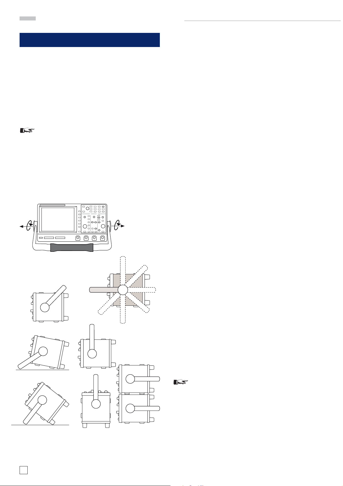
1.1. Setting up the instrument
As can be seen from the fi gures, the handle can be set into
different positions:
A and B = carrying
C = horizontal operating
D and E = operating at different angles
F = handle removal
G = operating using the feet‘s, batch use and for shipping in
original packaging
Attention!
When changing the handle position, the instrument
must be placed so that it cannot fall (e.g. placed on
a table). Then the handle locking knobs must be
simultaneously pulled outwards and rotated to the
required position. Without pulling the locking knobs
they will latch in into the next locking position.
Removal/fi tting of the handle: The handle can be removed in
position F, pulling the side parts outside the housing. Adding
the handle works vice versa.
1.2. Safety
The instrument fulfi ls the VDE 0411 part 1 regulations for
electrical measuring, control and laboratory instruments and
was manufactured and tested accordingly. It left the factory in
perfect safe condition. Hence it also corresponds to European
Standard EN 61010-1 and International Standard IEC 1010-1.
In order to maintain this condition and to ensure safe operation the user is required to observe the warnings and other
directions for use in this manual. Housing, chassis as well as
all measuring terminals are connected to safety ground of the
mains. All accessible metal parts were tested against the mains
with 2200 V
oscilloscope may only be operated from mains outlets with a
safety ground connector. The mains plug has to be installed
prior to connecting any signals. It is prohibited to separate the
safety ground connection. If suspected that safe operation may
not be guaranteed do not use the instrument any more and lock
it away in a secure place.
Safe operation may be endangered if any of the following was
noticed:
– in case of visible damage.
– in case loose parts were noticed
– if it does not function any more.
– after prolonged storage under unfavourable conditions (e.g.
like in the open or in moist atmosphere).
– after any improper transport (e.g. insuffi cient packing not
conforming to the minimum standards of post, rail or transport fi rm)
. The instrument conforms to safety class I. The
DC
Removing the handle (Pos. F)
A
C
D
D
B
A
1.3. Correct operation
Please note: This instrument is only destined for use by personnel well instructed and familiar with the dangers of electrical
measurements. For safety reasons the oscilloscope may only
be operated from mains outlets with safety ground connector.
It is prohibited to separate the safety ground connection. The
B
C
G
F
E
G
plug must be inserted prior to connecting any signals.
The oscilloscope is destined for operation in industrial, business,
manufacturing, and domestic sites.
1.4. Ambient conditions
Operating ambient temperature: +5 °C to +40 °C. During transport or storage the temperature may be –20 °C to +70°C. Please
note that after exposure to such temperatures or in case of
condensation, proper time must be allowed until the instrument
has reached the permissible temperature, and until the condensation has evaporated before it may be turned on! Ordinarily
this will be the case after 2 hours. The oscilloscope is destined
for use in clean and dry environments. Do not operate in dusty
or chemically aggressive atmosphere or if there is danger of
explosion. The any operating position may be used, however,
suffi cient ventilation must be ensured. Prolonged operation
requires the horizontal or inclined position.
Do not obstruct the ventilation holes!
Specifi cations are valid after a 30 minute warm-up period at 23
degr. C (tolerance ±2 degr. C). Specifi cations without tolerances
are average values.
E
Positions of the instrument
6
Subject to change without notice
1.5. Warranty and repair
HAMEG instruments are subjected to a strict quality control.
Carrying positionsOperating positions
Stacking positions
Prior to leaving the factory, each instrument is burnt in for 10
hours. By intermittent operation during this period almost all
defects are detected. Following the burn in, each instrument is
tested for function and quality, the specifi cations are checked
Page 7
Installation and safety instructions
in all operating modes; the test gear is calibrated to national
standards.
The warranty standards applicable are those of the country
in which the instrument was sold. Reclamations should be
directed to the dealer.
Only valid in EU countries
In order to speed claims, customers in EU countries may also
contact HAMEG directly. Also, after the warranty expired, the
HAMEG service will be at your disposal for any repairs.
Return material authorization (RMA):
Prior to returning an instrument to HAMEG, ask for a RMA
number either by internet (http://www.hameg.com) or fax (+49
(0) 6182 800 501). If you do not have an original shipping carton,
you may obtain one by calling the HAMEG service dept (+49 (0)
6182 800 500) or by sending an email to service@hameg.com.
1.6. Maintenance
Clean the outer case using a dust brush at regular intervals.
Dirt can be removed from housing, handle, all metal and plastic
parts using a cloth moistened with water and 1 % detergent.
Greasy dirt may be removed with benzene (petroleum ether) or
alcohol. Thereafter wipe the surfaces with a dry cloth. Plastic
parts should be treated with a suitable antistatic solution. No
fl uid may enter the instrument. Do not use other cleansing
agents as they may adversely affect the plastic or lacquered
surfaces.
The holder with the new fuse can then be pushed back in place
against the spring. It is prohibited to ”repair“ blown fuses or to
bridge the fuse. Any damages incurred by such measures will
void the warranty.
Type of fuse:
Size 5 x 20 mm; 250V~, C; IEC 127, Bl. III; DIN 41 662 (or DIN 41
571, Bl. 3). Cut off: slow blow (T) 2A.
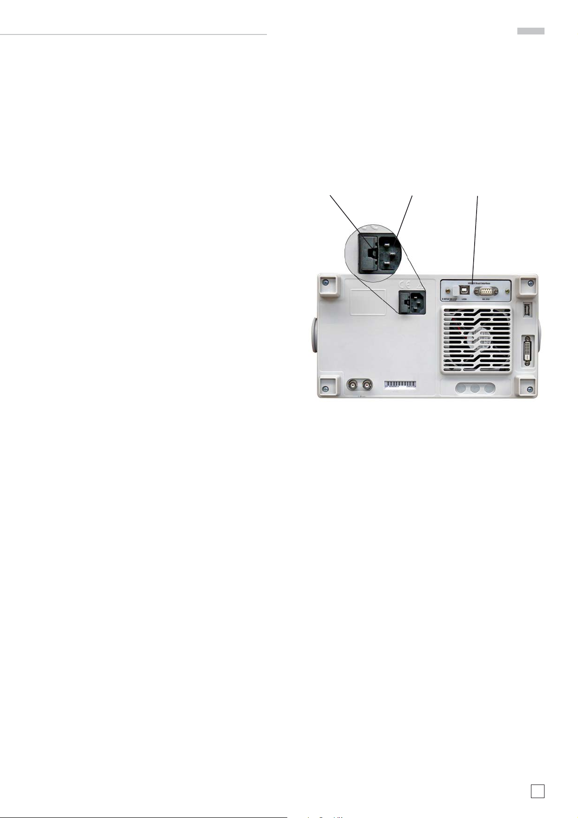
Fuse Mains input connector Interface
1.7. CAT I
This oscilloscope is destined for measurements in circuits not
connected to the mains or only indirectly. Direct measurements,
i.e. with a galvanic connection to circuits corresponding to the
categories II, III, or IV are prohibited! The measuring circuits
are considered not connected to the mains if a suitable isolation
transformer fulfi lling safety class II is used. Measurements
on the mains are also possible if suitable probes like current
probes are used which fulfi ll the safety class II. The measurement category of such probes must be checked and observed.
The measurement categories were derived corresponding to
the distance from the power station and the transients hence to
be expected. Transients are short, very fast voltage or current
excursions which may be periodic or not.
Measurement CAT IV: Measurements close to the power station,
e.g. on electricity meters
Measurement CAT III: Measurements in the interior of buildings
(power distribution installations, mains outlets, motors which
are permanently installed).
Measurement CAT II: Measurements in circuits directly connected to the mains (household appliances, power tools etc).
Measurement CAT I: Electronic instruments and circuits which
contain circuit breakers or fuses.
Type of fuse
1.8. Mains voltage
The instrument has a wide range power supply from 105 to
253 V, 50 or 60 Hz ±10%. There is hence no line voltage selector.
The line fuse is accessible on the rear panel and part of the line
input connector. Prior to exchanging a fuse, the line cord must
be pulled out. Exchange is only allowed if the fuse holder is
undamaged. It can be taken out using a screwdriver put into the
slot. The fuse can be pushed out of its holder and exchanged.
Subject to change without notice
7
Page 8

Introduction
SCALE
VOLTS / DIV
Y-POSITION
CHANNEL CONTROL
FINE
6
2
-
K
3
0
4
-
1
1
5
0
-
1
.
0
MENU
CH1
CH2
CH3
POD1
MATH
REF
X Y
CH4
POD2
CURSOR/MENU ANALYZE GENERAL
CURSOR
SELECT
CURSOR
MODE
AUTO
MEASURE
SCROLL
BAR
CURSOR
MEASURE
FFT
QUICK
VIEW
DISPLAY
AUTO
SET
SETUP HELP
SAVE
RECALL
INTENS
PERSIST
FILE
PRINT
USB STICK
HMO 3524
HMO 3524
350 MH z / 4 GSa / 2 MB DIGI TAL OSCIL LOSCOP E
350 MH z / 4 GSa / 2 MB DIGI TAL OSCIL LOSCOP E
POD 2 (15..8) POD 1 (7..0)
LOGIC CHANNELS REM CH 1
Use recommended probes only!
!!
54
PROBE ADJUST
1 kHz / 1 MHz
ca. 0.2 Vpp
Made in
Germany
1
2
CURSOR/MENU ANALYZE GENERAL
CURSOR
SELECT
SCROLL
BAR
CHANNEL CONTROL HORIZONTALTRIGGER
X Y
SCALE
VOLTS / DIV
K
3
-
0
2
4
6
-
1
1
5
0
-
1
.
0
MENU
CH 2 CH 3 CH 4
1MΩ II 13pF
max.
200 Vp
CH1
CH2
CH3
POD1
CH4
POD2
MATH
REF
≤5V RMS
A
CURSOR
INTENS
PERSIST
CURSOR
MEASURE
50Ω
!
CAT I
MODE
FFT
QUICK
VIEW
AUTO
MEASURE
LEVELY-POSITION X-POSITION
AUTO
SINGLE
NORM
TRIG’d SLOPE
SLOPE
TYPE
SOURCE
FILTER
RECALL
SETUP HELP
DISPLAY
SET
CLR
RUN
STOP
M
1MΩ II 13pF
max.
200 Vp
SAVE
E
M
SCALE
TIME / DIV
O
R
Y
ACQUIRE
MENU
TB/ZFINE
AUTO
SET
FILE
PRINT
Fig. 2.1: Frontview of the HMO3524
2 Familiarize yourself with your new HAMEG
Digital Storage Oscilloscope
2.1. Front view
The following controls and inputs/outputs are located on the
front: Power switch
connectors of the analog inputs
50
output
51 52
LED
, the connectors for the optional logic probes HO3508
, a USB port for USB sticks 53 , the TFT screen 54 and the
49
for showing activity on the remote interface.
1
, the control panel 2, A,B,C,D, the BNC
45
to 48, the probe adjustment
Please note, the connectors for the active logic
probes HO3508
51 52
are solely for theses probes.
Connecting anything else could destroy the inputs!
2.2. Control panel
The controls on the front panel allow direct access to the most
important functions; all extended functions are available via the
menu structure by using the grey soft keys. The power switch
1
is clearly set apart by its red colour. The most important
controls are backlighted by coloured LEDs in order to immediately indicate the actual settings. The panel is subdivided in
these four areas:
9
10
6
8
7
12 13
11 14
A
3
5
A
Area
Fig. 2.2:
Area A of the
control panel.
8
Subject to change without notice
4
49
48 47 46 4550515253
B C D
This area encompasses these three portions: CURSOR/MENU
– ANALYZE – GENERAL.
In the portion CURSOR/MENU you fi nd the cursor functions
6 8
, the general cursor select and adjustment knob 4, the
Intensity/Persistence key
7
, and the key for the selection of
virtual screen.
The portion ANALYZE allows direct selection of FFT
the Quick-view mode
10
(all important parameters of the ac-
tual signal display), and the „Automeasure“ function
9
displays,
11
for the
automatic measurement of parameters.
The portion headed GENERAL comprises the following keys:
SAVE/RECALL
12
for saving and recalling instrument settings,
reference signals, signals, screen displays, and sets of formulae, HELP
settings, AUTOSET
settings (e.g. the language), FILE/PRINT
B
Area
In the portion CHANNEL CONTROL
you fi nd all controls of the analog
channels such as the position control knob
19
key
15
16
, the vertical gain adjustment
20
knob
tions key
22
to 25, (the two-channel version
HMO3522 has only
also serve as the selection keys for
17
Fig. 2.3: Area B of the
control panel.
16
, DISPLAY 14 for access to the general display
15
, SETUP 13 for access to the general
:
18
, the XY mode select
, the extended menu func-
21
, the channel select keys
22 23
) which
17
.
B
22
18
23
19
24
25
20
26
21
27
Page 9
Introduction
LEVEL
TRIGGER
TRIG’d SLOPE
AUTO
NORM
TYPE
SOURCE
FILTER
SLOPE
SINGLE
SCALE
TIME / DIV
X-POSITION
HORIZONTAL
TB/Z
M
E
M
O
R
Y
MENU
ACQUIRE
RUN
STOP
SET
CLR
the optional logic probes 24 25. There are also the mathematics
26
function key
C
Area
This area TRIGGER of the control
and the reference signal settings key 27.
:
C
panel offers all functions for the
adjustment of the trigger level
, the selection of auto or normal
trigger
trigger source
29
, the trigger type 31, the
32
, single sweep
, the trigger slope 34, the trigger
signal fi lters
36
. In addition, the-
re are status indicators showing
28
33
28
29
30
33
34
whether a signal fulfi lls the trigger
conditions
selected
Area
The keys
30
and which slope was
34
.
D
:
37 38 39
on this control
panel area HORIZONTAL allow to
31
32
Fig. 2.4: Area C of the
control panel
35
36
shift the trigger position horizontally, either step-by-step or using the
smaller one of the knobs. The backlighted key
39
controls the run or
stop modes; the key will light up red
in stop mode. The key
the zoom function, the key
40
activates
44
the
selection of the acquisition modes,
the key
base menus. The knob
42
the access to the time
43
allows to
D
37
38
37
39
41
42
adjust the time base speed.
To the left of the control panel there
are the soft keys
2
which control the
menu functions.
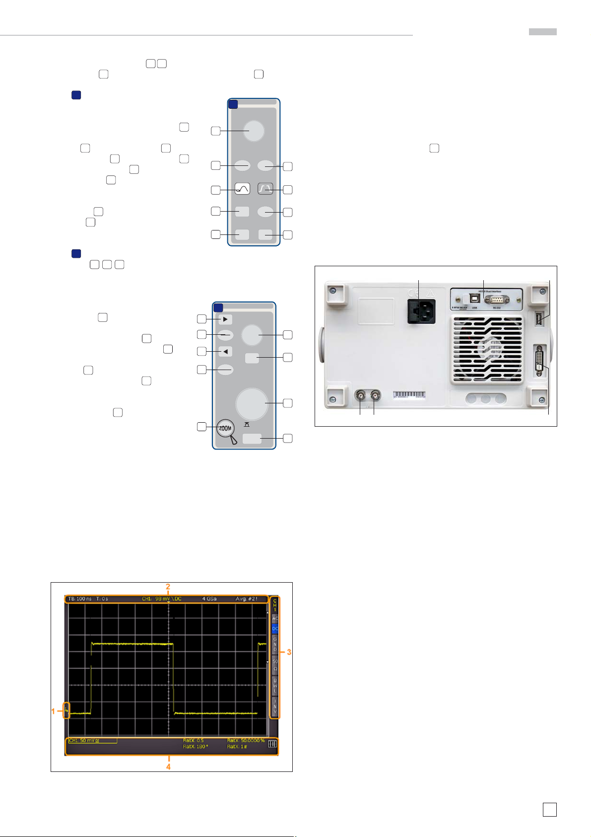
2.3. Screen
The HMO is equipped with a 6.5“
(16.5 cm) LED backlighted colour
40
Fig. 2.5: Area D
of the control panel
43
44
TFT display with VGA resolution (640
x 480 pixels). In normal mode (no menus shown) there are 12
divisions in X direction. If menus are shown, this will be reduced to 10 divisions. On the left of the screen area little arrows
[1] indicate the reference potentials of the channels. The line
above the graticule contains status and settings information
such as the time base speed, the trigger delay and other trigger
conditions, the actual sampling rate, and the acquisition mode
[2]. On the right of the graticule a short menu is shown which
contains the most important settings of the channel actually
being displayed; these may be selected using the soft keys [3].
Below the graticule, measurement results of parameters and
cursors, the settings of the activated vertical channels, of the
reference signal, and of the mathematically derived curves [4]
are shown. Within the graticule, the signals of the selected channels are displayed. Normally, 8 vertical divisions are shown; it
can be virtually extended to 20 divisions which can be displayed
using the SCROLL BAR knob
5
.
2.4. Rear view
On the rear panel there are the mains connector [1], the receptacle for the interface modules [2] (USB / RS-232, Ethernet,
IEEE-488), the standard DVI connector [3] for the connection
of external monitors and projectors, the BNC connector for
the Y output [4] (of the channel selected for triggering) and the
external trigger input [5]. With the two-channel models this
connector is located on the front panel.
[1] [2] [2]
[5] [4] [3]
Fig. 2.7: Rear panel of the HMO3524
2.5. Options
The HMO352x series instruments offer some options which
allow you to extend the areas of application considerably. The
following interface modules are available and may be installed
by the customer in the rear receptacle:
– HO740 (IEEE-4888, GPIB, galvanically isolated)
– HO730 (combination of Ethernet and USB with integrated
web server)
All HMO 352x series instruments are prepared for mixedsignal operation and have the appropriate connectors on the
front panel. Each of these connectors can be connected to an
8-channel logic probe HO3508, hence a maximum of 16 logic
channels is possible. More available options are the passive
500MHz slimline10:1 probes HZ355, the 19inch rack kit HZ46
and the carrying bag HZ99.
Fig. 2.6: Screen
2.6. General concept of instrument operation
HAMEG oscilloscopes are renowned for easy operation, based
on a few basic principles which repeat with the diverse settings
and functions.
– Such keys which do not open a soft menu (e.g. Quickview)
switch a function on, pushing the key again will switch the
function off.
– Such keys which call a specifi c function (e.g. FFT) which
in turn can call or require more settings will activate the
function upon the fi rst touch. Pushing the key a second time
will call the soft menu (sub menu) for the settings. Pushing
the key a third time will deactivate the function.
Subject to change without notice
9
Page 10
Introduction
– Such keys which open a soft menu upon the fi rst touch will
close it upon pushing a second time.
– The universal knob is used in the diverse menus either for
selecting numbers or submenus.
– The key MENU OFF below the soft menu keys closes the
present menu or it switches to the next higher level.
– If a channel is deactivated, pushing the respective channel
key will switch it on. If a channel was already activated
earlier, selecting another channel will change operation
to the channel whose key was pushed (its LED lights up). If
a channel is already selected, pushing its lighted key will
deactivate the channel and select the next channel according
to this sequence: CH1 > CH2 > CH3 > CH4.
– If cursor measurements are activated, the „CURSOR SE-
LECT“ key will select the cursor which can be moved with
the universal knob. In all menus for alpha-numeric inputs
and at the fi lemanager the knob is used to select or confi rm
entries.
The following describes some frequently used navigation elements in the soft menus.
In the Fig. 2.8 there are two basic soft menu elements for choosing
something are shown. To select from the fi rst three you just need
to press the soft key beside and the element is active (shown as
blue color). A second kind of selecting is shown on the lower two
menu entries. Pressing the respective soft key toggles between
the two choices, again the active selection is marked blue.
The menus are used as shown in Fig. 2.9 if they concern functions which have either to be switched on or where values have
to set. The choice is between OFF and the value presented. The
round arrow in the right corner of the menu window points to
the universal knob which is to be used for selecting the value. If
there is a lower menu level, this will be indicated by a small triangle in the right lower corner of the respective menu point.
If there are further pages on the same level, the lowest menu
point will be used for navigation. It shows the number of menu
pages on this level as well as the activated number of pages.
Pushing the respective soft menu key will advance by one page,
after the last page the fi rst one will follow.
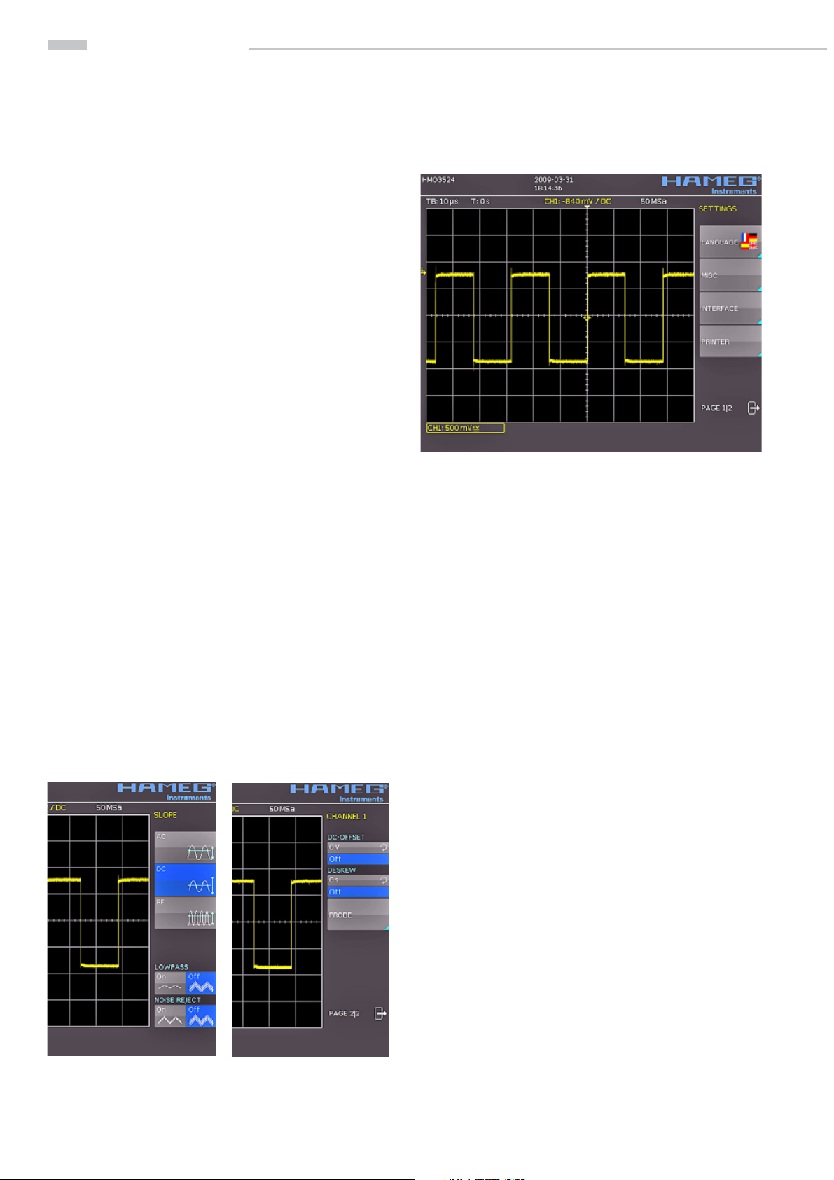
2.7. Basic setting and integrated help
Basic settings like language for user interface and help, miscellaneous settings and interface settings can be set using
the menu which opens after pressing the SETUP key in the
GENERAL area of the control panel
Fig. 2.10: Menu for basic settings
On the fi rst page you can set the user interface and help language by pressing the soft key LANGUAGE and select German or
English. (Complete support for French and Spanish for the help
function will be implemented latest in fi rmware 2.0.)
The soft key beside MISC opens a menu with the following
selections:
– MENU OFF (choose manual or automatic with time limit of
4s up to 30 s for closing soft menus)
– TIME REFERENCE (position for reference of the trigger time,
choose from -5/DIV up to +5/DIV, 0/DIV is in the middle of
the screen and set as standard)
– DATE & TIME (opens menu to set date and time)
– SOUND (opens menu to set any combination of beep for
control, error and/or trigger)
– DEVICE NAME (menu to set a name for the HMO352x, ma-
ximum of 19 characters are allowed, the name will appear
in Screenshot‘s)
– DEVICE INFOS (opens a window with detailed information
about hardware and software of your HMO352x)
Fig. 2.8: Selection of basic soft
menu elements
10
Subject to change without notice
Fig. 2.9: Basic soft menu
elements for settings and
navigation
The next menu entry INTERFACE lets you select the interface
you are using (USB and RS-232 are standard) and possible
settings for that interface.
The last menu entry PRINTER shows all settings for postscript
printer; beginning with fi rmware 2.0 there will be also support
for other compatible printer.
At the second page of the basic menu you fi nd the menu for
fi rmware and help update, which is explained in detail in the
next chapter. The last menu item is the PROBE ADJUST.
Pressing the soft key leads you to the menu where you can set
whether the probe adjust output generates a rectangular signal
with 1 kHz or 1 MHz frequency. There is a setting AUTOMATIC
which means, that for timebase settings up to and including
50 μs/DIV the probe adjust output is 1 MHz, from 100 μs/DIV on
it is switched to 1 kHz.
The integrated help function can be activated by pressing the
key HELP in the GENERAL area of the control panel. A window
will open and the text inside is dynamically updated depending
Page 11
Introduction
on the key (including softmenu key’s) you are pushing or the
knob you are turning. If you do not need the help anymore, you
can switch off the help window by pushing the “HELP” key. The
backlight of the key and the text window will be switched off.
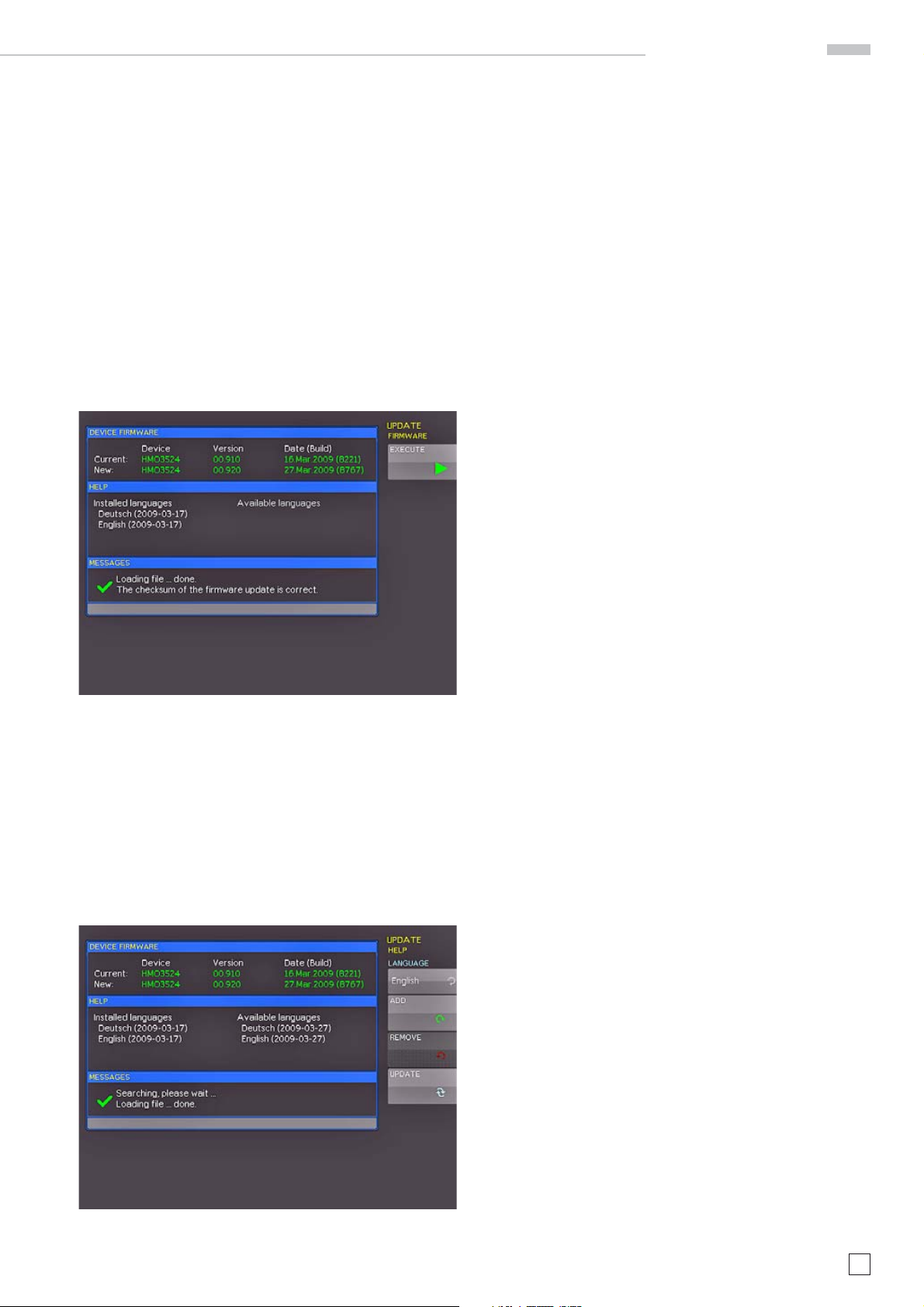
2.8. Firmware- and help updates
The HMO352x series is being improved continuously. You are
invited to download the most recent fi rmware under www.
hameg.com/hmo3524. Firmware and help are packed into one
ZIP data packet. After downloading the ZIP data unpack it into
an USB stick’s basic directory. Thereupon insert the stick into
the USB port of the oscilloscope and push the key SETUP in the
GENERAL area of the front panel. Choose page 2 in the menu,
if this has not been opened already. Here you shall fi nd the
menu item UPDATE. After selecting this menu item a window
will open which displays the actual fi rmware version indicating
the version number, the date and build information.
If you intend to update the help function or add a help language
choose HELP in the updating menu.
The information window will now display the languages installed, the date, and the information about the languages available
on the stick. With the soft menu, languages may be added,
removed or updated. Please note the format of the date:YYYYMM-DD according to the multi language norm of ISO 8601.
Fig: 2.11: Updating menu and information window
Now choose which to update: the fi rmware or the help function.
If both are to be updated it is recommended to fi rst update the
fi rmware. After you selected fi rmware updating by pushing
the appropriate key the respective date will be searched on
the stick, the information of the fi rmware to be updated from
the stick will be displayed below the line NEW. In case the new
fi rmware should be identical to the existing one, the number
of the version will be shown in red, otherwise it will be shown
in green; only then should you activate the updating by pushing
the soft key EXECUTE.
Fig. 2.12: Menu and information display of the help updating
Subject to change without notice
11
Page 12

A quick introduction
CURSOR/MENU ANALYZE GENERAL
CURSOR
SELECT
CURSOR
MODE
AUTO
MEASURE
SCROLL
BAR
CURSOR
MEASURE
FFT
QUICK
VIEW
DISPLAY
AUTO
SET
SETUP HELP
SAVE
RECALL
INTENS
PERSIST
FILE
PRINT
SCALE
TIME / DIV
X-POSITION
HORIZONTAL
TB/Z
M
E
M
O
R
Y
MENU
ACQUIRE
RUN
STOP
SET
CLR
3 A quick introduction
The following chapter is intended to introduce you to the most
important functions and settings of your new HAMEG HMO352x
oscilloscope in order to allow you to use the instrument immediately. The internal calibrator signal output is used as the
signal source, so you will not need any additional instruments
for the fi rst steps.
3.1. Setting up and turning the instrument on
Position the handle so the display will be inclined slightly upwards. (See chapter 1.2 for positioning of the handle.) Plug the
power cord into the rear panel connector. The instrument will
be turned on by pushing the red key On/Off
After a few seconds the display appears, and the oscilloscope
is ready for measurements. Now press the key AUTOSET
for at least 3 seconds.
9
10
3
4
A
7
6
12 13
1
on the front panel.
15
16
15
On the right hand side of the screen you will see a short menu of
channel 1, the soft keys allow you to select frequently used settings.
Press the top soft key once to change the input coupling to DC.
The actual settings are marked by underlying blue
fi elds, repeated pressing of the keys will alternate
between the settings.
Fig. 3.3: Screen display after changing to DC coupling
5
8
11 14
17
Fig. 3.1: Control panel HMO352x
3.2. Connection of a probe and signal capture
Take one of the probes HZ350 delivered with the instrument,
the ground cable and the probe tip.
The passive probes should be calibrated before
fi rst use. Please follow the instruction of the probe
manual. Please use the shortest ground connection
possible to the PROBE ADJUST output.
Connect the ground cable to the probe and the tip to the top of
the probe. Now connect the compensation box BNC connector
to the input connector of channel 1 and secure it by turning it
CW until it latches. Connect the ground cable to the left output
jack and hold the tip to the right jack of PROBE ADJUST. The
following display should be visible.
Fig. 3.2: Screen display after connection of the probe
12
Subject to change without notice
Now press the AUTOSET key 15 once shortly, after a few seconds
the oscilloscope will have automatically selected appropriate
vertical, horizontal time base and trigger settings. You will see
now a square wave signal.
Fig. 3.4: Screen display after Autosetup
3.3. Display of signal de-
tails
With the knob 43 you can change
the displayed time window: turning
it CCW will slow the time base. The
memory depth of 2 MB per channel
allows you to capture wide time windows with high resolution. Continue
to turn the knob CCW until you read
„TB:5ms“ in the top left corner. Now
press the ZOOM key
Fig. 3.5: Area of the control panel
containing the ZOOM knob
40
.
D
37
38
37
41
42
39
43
40
44
Page 13

A quick introduction
You see now a two-window display: the display will show in
the top area the complete captured signal, below an enlarged
portion. Use the time base knob to select the zoom factor and
the small knob for horizontal positioning.
Fig. 3.6: ZOOM function
By pressing the ZOOM key 40 again the zoom mode be will be
deactivated.
cursors will be switched off by pressing the CURSOR/MEASURE
key and the associated CURSORS OFF soft key.
3.5. Automatic measurements
In addition to cursor measurements the most important signal
parameters can be displayed. Your HAMEG oscilloscope offers
these possibilities:
– the defi nition of the display of 2 parameters which may come
from different sources
– a quick view of all important parameters of one source using
the QUICK VIEW function.
Please change the time base now to 100 μs/div. and press the
10
QUICK VIEW key.
.
3.4. Cursor measurements
After displaying the signal and its details we now proceed to
measuring it using the cursor functions. Press again shortly
AUTOSET
the cursor menu will open up, and you can select the kind of
cursor. Press the top soft key in order to open the appropriate
menu. Use the knob in the CURSOR/MENU area for the selection by turning it CCW until the V-marker is underlined, press
the CURSOR SELECT key or wait for some seconds in order
to accept the selection. Now two cursors will be displayed
along with the signal, and the measurement results in the
right bottom area of the screen. Select the active cursor with
the SELECT key
15
and then the CURSOR/MEASURE key 8. Now
3
and position it with the knob.
Fig. 3.8: Quick View parameter measurement
Here you see the most important parameters of a signal displayed:
– positive and negative – rise and fall times
peak voltages – mean voltage
In the right bottom corner of the screen 4 more parameters
are shown:
– rms value – peak-to-peak voltage
– frequency – period
Thus by simply pressing a key you see 9 parameters at a glance
which characterize the signal. This function applies always to
the acutal active channel.
You may also display two parameters of two different signals. In
order to achieve this deactivate the QUICK VIEW function by pressing the key again, then activate channel 2 by pressing the CH2 key.
Open the following menu by pressing AUTOMEASURE
11
:
Fig. 3.7: Cursor measurements
The cursor measurement results will be displayed in the left
bottom corner of the screen. In this case the „V cursor“ has selected the voltages at the two cursor positions, their difference,
and the time difference between the positions will be shown. The
Fig. 3.9:
AutoMeasure
Subject to change without notice
menu
13
Page 14

A quick introduction
The two parameters are displayed in the right bottom corner of
the screen. You may defi ne the parameter measurement using
this menu. After switching on MEASURE 1 and MEASURE 2 with
the appropriate softkey’s the parameter measurements are
displayed in the right bottom corner of the screen. If you press
the softkey beside TYPE you can choose the parameter you want
from the list using the general knob. This procedure is used in
all menus where choices are available. Please press the key
TYPE and choose risetime.
Fig. 3.12: Formula editor
In order to change the settings use the soft keys and the universal
knob . Here you can program and store the formulae most used.
As mentioned earlier these formulae can be quickly switched on
and off by pessing the MATH key
26
and using the appropriate
short soft menue.
Fig. 3.10: Selection of parameters
Now use soft key next to Source 2 in order to select this menu item
and thus channel 2. Now the rise time of channel 1 and the mean
value of channel 2 are shown. After the menu has been closed,
the parameters can be identifi ed by the colours of the respective
channels, (here yellow for channel 1 and blue for channel 2.)
3.7. Storing data
Your HMO352x can store 5 different kinds of data:
– Instrument settings
– Reference signals
– Signals
– Screen displays
– Sets of formulae.
Signals and screen displays can only be stored on USB sticks.
All other data can be stored either on a USB stick or in the
instrument’s non-volatile memories. In order to store data you
have to defi ne the kind of data and the destination. First attach
a USB stick to the front panel connector. Press SAVE/RECALL
12
in order to call the respective menu.
Fig. 3.11: Measuring the parameters of two sources
3.6. Mathematical functions
In addition to cursor and parameter measurements your HMO
can also apply mathematical functions to the signals. By pressing the MATH key a short menu will open which allows you to
select one or two predefi ned mathematical functions. A quick
setting of mathematical functions is possible by selecting the
menu item at the bottom. This mode allows you to select the
addition or subtraction of two activated sources. The formula
editor allows to predefi ne 5 possible mathematical functions,
it is called by pressing the MATH key (which lights up red) and
the MENU key
14
Subject to change without notice
21
.
Fig. 3.13: Save/Recall menu
Select the kind of data by pressing the respective soft key (in
this example SCREENSHOTS) in order to access the settings
menu.
Page 15

SCALE
VOLTS / DIV
Y-POSITION
CHANNEL CONTROL
FINE
6
2
-
K
3
0
4
-
1
1
5
0
-
1
.
0
MENU
CH1
CH2
CH3
POD1
MATH
REF
X Y
CH4
POD2
Vertical system
4 Vertical system
Fig. 3.14: Menu SCREENSHOTS
Please verify that the USB connector into which you plugged the
USB stick (front or rear) is written in the top soft menue (You
can change the destination by opening the respective menu if
you press the softkey next to STORAGE). You can now save a
Screenshot if you press the softkey next to SAVE using the predefi ned name written in the menu below FILE NAME. You may
name the destination memory with up to 8 characters; in order
to do this select the menu item FILE NAME and defi ne the name
by using the universal knob and the CURSOR SELECT key.
For the vertical settings there are
the knobs for the vertical position
and the sensitivity, an always visible short menu and an extended
menu.
B
22
18
23
19
24
25
20
26
Fig. 4.1: Front panel area with
vertical system controls
21
27
By pushing the respective key the channel will be selected for
which these controls will be activated, this will be indicated by
the key lighting up in the color of the channel. Additionally, the
channel number on the screen will be framed and displayed
lighter than the channels not activated. The appropriate short
menu is always visible, the extended menu will be shown upon
pushing the key MENU
21
.
Fig. 3.15: Defi ning a fi le name
After the soft key next to Accept was pressed the oscilloscope
will have stored the name and return to the settings menu. Here
you can now store the actual screen display by pressing the
STORE soft key. Alternatively, you can return to a lower menu
level (by pressing the lowest Menu OFF key) and select the
menu item key FILE/PRINT. In the following menu press the soft
menu key next to SCREENSHOTS: this will assign the function
Screen Shot to the key FILE/PRINT with the settings chosen.
This enables you to store a bit map fi le on your USB stick by just
pressing FILE/PRINT
17
at any time and in any menu.
Fig. 4.2: Short menu for the vertical settings
4.1. Coupling
The fi rst item to be selected is the input impedance: 1MΩ or
50 Ω.
Do not connect the 50 Ω inputs to effective voltage
higher than 5 volts!
The 50 Ω input impedance should only be selected if the signal source is 50 Ω, such as a generator with a 50 Ω output
where the termination within the scope is to be used. In all
other cases 1 MΩ is to be selected. Next DC or AC coupling
has to be selected: with DC coupling all components of the
signal will be displayed, with AC coupling the DC content will
be removed, the lower bandwidth is 2 Hz. Up to 250 V
be applied directly to the vertical inputs if 1 MΩ is selected.
Higher voltages can be measured with probes (up to 40 KVp).
For general applications the probes HZ350 (10:1, 10 MΩ II 12 pF,
max. 400 Vp) supplied with the instrument will be used. They
are specifi ed for the 1 MΩ input; the probe factor will be read
from the probe and factored in; they feature a 10 MΩ impedance
at low frequencies.
Subject to change without notice
rms
may
15
Page 16

Vertical system
The passive probes must be adjusted to the inputs
to which they are connected. See the probe manual
for the adjustment procedure. The PROBE ADJUST
output is only usable for 1:1 and 10:1 probes, for
100:1 or 1000:1 probes special external generators with a perfect step response have to be used.
Please use the shortest possible ground connection.
The coupling is selected in the short menu: by just pushing the
appropriate key the coupling is chosen, also the signal may be
inverted. The menu is valid for the activated channel as indicated
by the channel key light up. The channel number will be shown
in the top of the menu. By pushing the respective key of another
channel the menu will transfer to this channel.
4.2. Sensitivity, Y-Positioning, and Offset
The sensitivity of the analog inputs can be selected with the large
knob in the CHANNEL CONTROL section of the front panel in
1-2-5 steps from 1 mV/div to 5 V/div independent of the 50 Ω or
1 MΩ selection. The knob is associated with the channel selected
by pushing the respective key. The sensitivity can be changed
to continuous control by pushing the knob once. The smaller
one of the knobs is used for vertical positioning.
By pushing the MENU key the extended menu is called. On page
2 of this menu a DC offset can be added to the signal. In order
to switch this offset in the respective soft key must be pushed.
The settings window will be backlit in blue, and the activity
indicator next to the general knob will light up; the offset can
now be adjusted with the knob. The offset voltage will be added
to the signal at the vertical amplifi er input offsetting it by that
amount from the zero position. The possible amount of offset
depends on the Volts/div setting chosen. The offset function
being activated will be indicated by two channel markers on
the left of the display, also visible if the menu was closed. One
marker indicates the position, the other the offset (refer to Fig.
4.3). The offset is individually adjustable for each channel.
higher frequency interference. The fi lter is activated in the
short menu by pushing the respective soft key; the information
fi eld will be backlit in blue, BW will be displayed in the channel
information window.
Signal inversion is available in the short and the extended menus. If it is activated the information fi eld will be backlit in blue,
and there will be a bar above the channel number.
4.4. Probe attenuation selection
The HZ350 probes supplied with the instrument will be recognized by the instrument which automatically selects the
appropriate factor. If any other probe without automatic recognition of the attenuation ratio or just a cable is connected to the
instrument, the attenuation factor can be set manually in the
extended menu. This is possible for x 1, x 10, x 100 x 1000 or as
defi ned by the user from x 0.001 to x 1000.
Each analog channel may also be shifted in time by ±15 ns. This
adjustment is selected in the same menu and according to the
same method as the DC offset; it is used for compensating for
the different signal delays of voltage and current probes and
different cable lengths.
4.3. Bandwidth Limit and Signal Inversion
An analog 20 MHz low pass can be inserted in the signal path
in either the short or extended menu. This will eliminate all
Fig. 4.3: Vertical offset in the extended menu
16
Subject to change without notice
Page 17

Horizontal System (Time Base)
SCALE
TIME / DIV
X-POSITION
HORIZONTAL
TB/Z
M
E
M
O
R
Y
MENU
ACQUIRE
RUN
STOP
SET
CLR
5 Horizontal System (Time Base)
As well as time base settings, the
horizontal system comprises the
selection of the trigger position, the
zoom functions and the available
modes of signal capture. The knobs
are used for the adjustment of the
time base speed and the trigger position. The signal capture modes are
selected in the respective menus.
There is a key provided for activating
the zoom function.
Fig. 5.1: Control panel of the
horizontal system
D
37
38
37
39
40
41
42
43
44
5.1. Capturing modes RUN and STOP
The capturing modes can be selected with the key RUN/STOP.
In RUN mode signals will be continuously captured; depending
on the trigger conditions selected, and displayed, erasing the
previously captured ones. If it is desired to store and further
analyze a signal and to prevent it being overwritten, capture
must be stopped by pushing the RUN/STOP key. While in STOP
mode capture is disabled and the key will light up red.
5.2. Time base adjustments
The large knob in the HORIZONTAL section of the control panel
is used for the selection of the time base speed. The time base
speed is displayed in the upper left hand corner above the
graticule. (e.g. „TB:500 ns“) To the right there is the display of
the trigger time position with respect to the normal position.
The normal trigger position is in the center of the graticule
such that 50 % of the signal display is before and 50 % is after
this trigger position. The X POSITION knob allows continuous
adjustment of the X position. The available maximum values
depend on the time base setting. By pushing the key SET/CLR
the value will be reset to its reference position. The arrow keys
37 allow you to change the X position by a fi xed amount of
5 divisions in the respective direction. The key MENU opens
a menu which allows you to set the X position to its minimum
and maximum positions by just a key touch. In addition, there
is a submenu NUMER.INPUT which allows entr y of an arbitrary
X position.
– Average:
Functions only with repetitive signals. The universal knob in
the CURSOR/MENU section of the front panel is used to set
the number of signal periods for averaging, this is possible
in powers of 2 from 2 to 256. Please note: Averaging reduces
the bandwidth.
– Smoothing:
In this mode continuous averaging is used which allows in-
crease of the vertical resolution at the expense of bandwidth
reduction.
The second menu page is accessed by pushing the soft key
next to the menu „Page 1/2“, here, extended functions are
available:
– RANDOM SAMPL:
For very fast signals displayed with the fastest sweep speeds
it can be advantageous to switch the instrument to Random
Sampling mode; in this mode very many signal periods are
used to generate a high resolution picture, provided the
signal does not change its shape. This is equivalent to a
sampling rate of approx. 50 GSa/s. The oscilloscope will
not automatically enter this mode, however, it is possible to
select automatic switching to Random sampling >20 ns/div..
The mode can be disabled by pushing the soft key.
– PEAK VALUE:
At very slow sweep speeds fast signal details will not be
visible. By selecting this mode peaks will be detected. This
function can be switched on or off in the menu, it is also
possible to select automatic switching in.
All the preceding functions are normally off. The lowest item in
the soft menu allows you to select the preferred signal capturing
repetition rate, there are 3 options:
– MAX. REP RATE:
In this mode an optimum combination of sampling rate and
memory length used will be selected automatically such that
the signal capturing rate will be maximized.
– MAX. SAMPL. RATE:
In this mode the maximum possible sampling rate will be
used.
– AUTOMATIC:
This mode is the standard mode: the instrument always
selects the optimum combination of capturing and sampling
rates (full memory length used).
5.3. Capture modes
The capture modes are selected by pushing the key ACQUIRE,
this opens a display menu which offers the 5 basic modes of
capture:
– Normal:
In this mode the signals are captured and displayed.
– Roll:
This is a mode especially useful for very slow signals: the
signal „rolls“ slowly untriggered from right to left over the
screen (signals must be slower than 200 kHz).
– Envelope:
In this mode the signal will be displayed as in NORMAL,
but its minimum and maximum excursions will also be
displayed such that, with time, an envelope of the signal
will be displayed.
5.4. ZOOM function
The HMO352x oscilloscope features a memory depth of 2 MB
per channel, this allows you to record long complex signals
which can be analyzed in detail with the ZOOM function. Push
the ZOOM key to activate this function. The screen will be partitioned into two graticule areas: the top one displays the whole
time base window; the lower one displays the zoomed portion of
it. The zoomed portion will be indicated in the upper display by
two blue cursors. With multi channel displays all channels will
be zoomed by the same factor and on the same portion.
In Fig. 5.2 a signal was recorded for 12 ms, the zoom window
is shown with a time scale of 100 μs/div. The time base speed
display in the left upper corner is shown with a grey background,
the zoom time base display is shown in white. This means that
the large knob in the horizontal menu is now available for changing the zoom factor. This knob also features a push contact; if
Subject to change without notice
17
Page 18

Horizontal System (Time Base)
LEVEL
TRIGGER
TRIG’d SLOPE
AUTO
NORM
TYPE
SOURCE
FILTER
SLOPE
SINGLE
the knob is pushed, the time base display will change to white,
and the zoom time base display to grey: now the knob is available
for changing the time base setting. This allows you to change
time base settings without leaving the zoom mode. The position
of the zoomed portion can be moved with the small knob in the
horizontal section of the front panel over the whole captured
signal. If pushing the large knob as described above would infl uence the time base setting and not the zoom factor, the small
knob regains the function of shifting the trigger position so the
relationship of pre to post trigger record can be changed.
6 Trigger System
The trigger system of the HMO is
easy to handle by just observing
the HAMEG concept of instrument
operation.
Fig. 6.1: Front panel control area of
the trigger system
There are 4 keys destined for frequently used functions:
– TYPE: selects the type of trigger: SLOPE, PULSE, LOGIC,
VIDEO and the B-TRIGGER.
– SLOPE: selects the slope polarity.
– SOURCE: opens the menu for the selection of the trigger
source.
C
28
29
30
31
32
33
34
35
36
Fig. 5.2: ZOOM function
– FILTER: opens the menu for the selected trigger type in
order to select the exact trigger conditions.
Additional keys are provided for the selection of the trigger
modes: (AUTO. NORMAL, SINGLE).
6.1. Trigger modes Auto, Normal, Single
The basic trigger modes are directly selectable with the key
AUTO NORM. In AUTO mode the key will not be lit. If the key is
pushed it will light up red indicating NORMAL mode.
The oscilloscope always presents a signal in AUTO mode and
a signal will automatically yield a stable display if it fulfi lls the
trigger conditions.
In NORMAL mode the signal will be displayed if it fulfi lls the
trigger conditions, if it fails to do so the last stable triggered
display will remain on the screen.
If it is desired to record a signal which fulfi lls the trigger con-
18
Subject to change without notice
Fig. 6.2: Coupling modes with slope trigger
Page 19

Trigger System
ditions only once, the key SINGLE must be pushed, it will light
up white. This indicates that the single trigger mode is active,
the RUN/STOP key will blink. The next return of the signal will
cause a single capture, the oscilloscope then goes into the STOP
mode, indicated by the RUN/STOP key lighting up in red.
6.2. Trigger sources
Trigger sources are the 2 (with HMO3522) or 4 (with HMO3524)
analog channels and the external trigger input. If the optional
logic probe HO3508 with 8 or 16 logic channels is connected,
also those up to 16 digital channels can serve as trigger
sources.
6.3. Slope trigger
The simplest and most used trigger type is slope trigger, this
one is also selected in the AUTOSETUP function. Pushing the
AUTOSETUP key will hence change any previously selected
trigger type to slope trigger. For the selection of the trigger
type push the key TYPE in the trigger control section of the front
panel. A menu will open and offer the options. If the type SLOPE
was not selected (blue background) pushing the respective soft
key will change to slope. The SLOPE key is also used to step
through the options rising, falling, or both slopes. In the center
of the status line top center above the graticule the type selected
will be shown. If the key FILTER is pushed, the respective menu
will open and offer the available options.
Here the trigger signal coupling can be selected:
DC: The trigger signal is used with its dc content.
AC: The trigger signal is routed via a 5 Hz high pass fi lter.
HF: The trigger signal is routed via a 15 kHz high pass fi lter.
The trigger level is no longer adjustable. This mode
should only be used with very high frequency signals.
LOW PASS: The trigger signal is routed via a 5 kHz low pass
fi lter.
NOISE RED.: The trigger signal is routed via a 100 MHz low
pass fi lter removing higher frequency interference.
The coupling modes low pass and noise reduction can not be
simultaneously selected, but they can be used with DC or AC
coupling.
The slope trigger can be coupled with a so called „B Trigger“.
This option is available after pushing TYPE. This function allows
you to adjust the trigger such that fi rst condition „A“ must be met
and then another condition „B“ before the trigger will respond
(refer to Fig. 6.3).
E.g. it is possible to defi ne a source (channel) and a level of
120 mV on the rising slope of that signal and for the second
condition a level of 80 mV on the falling slope. Additionally, it is
possible to defi ne whether the B event should occur a time (min.
8 ns) or a number (min. 1) of times after the A event. The level or
time or the number of events can be entered numerically with
the universal knob or in a submenu. In order to do this fi rst select
the setting, then push the soft key next to NUMER. ENTRY. In
the window which will open, you can enter numbers and units
with the combination of universal knob, the CURSOR SELECT
key and the visible softmenu functions.
6.4. Pulse trigger
The pulse trigger allows you to trigger on fi nite pulse widths of
positive or negative pulses, or ranges thereof. Select the pulse
trigger by pushing the key TYPE and the respective soft key
next to PULSE. Further settings are available in the soft menu
after pushing FILTER.
There are 6 options:
ti ≠ t: The pulse width ti is unequal to the reference width t.
ti = t: The pulse width ti is equal to the reference width t.
ti < t: The pulse width ti is smaller than the reference width t.
ti > t: The pulse width ti is greater than the reference width t.
t
<ti<t2: The pulse width ti, is smaller than the reference width
1
t
and greater than the reference width t1.
2
not(t
<ti<t2): The pulse width ti, is greater than the reference
1
width t
and smaller than the reference width t1.
2
First select the desired option and then adjust the desired reference time. If you choose „ti ≠ t“ od „ti = t“, you can select the
reference time after pushing the soft key next to TIME by turning
the universal knob. If you choose the soft menu item DEVIATION
the universal knob is used to defi ne a tolerance interval. If you
chose ti < t or ti > t, you can only defi ne one limit. Both options
with two references (t
spective soft key and turning the universal knob. All these settings
can be combined with positive or negative pulses by selecting
the respective soft menu keys. With positive pulses the width is
defi ned from the rising to the falling slopes, with negative pulses
from the falling to the rising slopes. Triggering will then be on the
second slope of the pulse.
and t2) can be set due to pressing the re-
1
Fig. 6.3: The type B-Trigger
Fig. 6.4: Pulse trigger menu
Subject to change without notice
19
Page 20

Display of signals
6.5. Video trigger
The video trigger allows you to trigger on PAL or NTSC standard
video signals. Select this mode by pushing the key TYPE in the
trigger control section of the front panel. The source is again
selected after pushing the key SOURCE. In the menu which
opens after pushing the key FILTER all further settings may
be performed.
First select the video standard PAL or NTSC by pushing the
respective soft key. As usual the selection will be indicated by
a blue background in the menu. The second setting will apply
to the polarity of the sync pulses. Next either the mode LINE
or FRAME can be selected. If LINE was selected, the precise
number of a desired line can be selected with the universal knob
from the 8th to the 623rd; this will be activated by pushing the
soft key next to the line number. The two other menu items allow
fast selections: LINE MIN sets the trigger line to the minimum
value, ALL LINES will cause triggering on any line. If FRAME
was chosen, the lower menu items will allow to trigger on ALL,
only the ODD or only the EVEN half frames.
7 Display of signals
The following chapter describes the selection and display of signals from various sources and the available display modes.
7.1. Display settings
The HMO352x features a high quality TFT – VGA (640 x 480 pixel
resolution) display with LED backlighting. The basic settings will
become accessible in the menus which will open after pushing
the key DISPLAY in the GENERAL section of the front panel. If
the menu item SCROLL MODE is activated, a rolling bar will
appear to the right of the graticule; a virtual display window of
20 divisions will become available which can be shifted up and
down with the universal knob. A detailed description will follow
in the next chapter.
There are 3 more menu items on the fi rst page:
DOTS ONLY:
The respective soft menu key will toggle between ON and OFF. If
ON is activated, only the captured samples will be shown as dots.
If OFF is activated, interpolated points will be shown as well.
INVERSE LIGHT:
The respective soft menu key will toggle between ON and OFF.
If ON is activated, those display points will be shown darker
which appear most frequently. If OFF is activated, they will be
shown brighter.
Fig. 6.5: Video trigger menu
FALSE COLOURS:
The respective soft menu key will toggle between ON and OFF.
If ON is activated, the color of the display points are shown
from blue over magenta, red and yellow up to white with growing number of appearing points. If OFF is activated, the most
frequently appearing ones will be shown brighter and the rarer
ones darker.
GRATICULE:
If this menu item is selected, the submenu which opens up will
allow you to choose:
LINES:
The graticule is divided into horizontal and vertical divisions.
CENTER CROSS:
There will be just one center vertical line and one center horizontal line; the divisions will be marked by dots.
OFF: The screen will be empty.
INFO WINDOW:
If this menu item is selected, a submenu will open up which
allows change of the transparency of the info windows (e.g.
for showing changes of the offset) from 0 to 100 %. This is done
with the universal knob. The info windows of the POSITION
and the CURVE INTENSITIES may be switched on or off if their
respective menus are chosen.
20
Subject to change without notice
AUX. CURSORS:
Pushing the respective soft menu key will open a submenu
which allows you to switch the auxiliary cursors for the trigger
level, the trigger time and the channel cursors on or off.
7.2. Use of the virtual screen area
The HMO graticule has 8 vertical divisions but there is a virtu-
Page 21

Display of signals
al range of 20 divisions. These may be used by the 16 digital
channels D0 to D15, the math functions and the references.
The analog channels can only use up to ±5 divisions from the
center.
Fig. 7.1: Drawing of the virtual screen area and an example
The picture above explains the function of the virtual screen. The
visible 8 divisions are shown in grey; this is the area available
for analog signals. To the right of the graticule there is a small
bar which indicates the position of the visible 8 divisions within
the possible 20 divisions. By pushing the key SCROLL BAR the
bar will be activated indicated by its color changing to blue; now
turning the universal knob will shift the visible 8 divisions (grey
area) within the available 20 divisions. This allows a simple and
clear display of many individual signal portions.
be changed with the universal knob. The soft menu key next
to the lowest menu item toggles between HIGH and LOW of
the LED’s of all backlit keys and all other LED displays on the
front panel.
After selecting the menu items PERSISTENCE and ADJUST the
persistence function can be defi ned: there are 3 choices for the
duration of the persistence: OFF, AUTOMATIC and MANUAL. In
MANUAL operation, the duration can be changed with the universal knob from 50 ms to infi nity. If a fi nite time was selected,
the signal periods will be written on top of each other such that
the brightness will diminish from recent to oldest. If e.g. 300 ms
is selected, the signal curves will become darker in 50ms steps
and erased after 300 ms. In this soft menu the function BACKGROUND may be activated in addition: then all signal curves
ever displayed will be shown in the darkest colour.
7.3. Signal intensity and persistence functions
In the standard mode, the key INTENS/PERSIST will light up
white: the intensity of the signal display can be changed with the
universal knob from 0 to 100 %. The persistence mode may be
selected for the display of varying signals: this is a storage mode
such that several curves may be written to remain on the screen.
Also the so called „Variable Persistence“ may be selected: in
this mode the persistence can be changed from 50 ms to infi nity;
this will cause the most recent portion of the signal to appear
bright while the preceeding portions will fade in proportion to
the time elapsed. This mode can be selected in the soft menu
which will open upon pushing the key INTENS/PERSIST; the
signal intensity can be changed also in this menu.
Fig. 7.3: Persistence function
This kind of display is for example very useful for the analysis
of extreme values of different signals.
7.4. XY display
The HMO352x has a key for directly switching to the XY function.
In this mode, two signals will be displayed, one in Y, one in X
direction. The usual time base will be replaced by the amplitudes of the second signal. With harmonically related signals
the resulting curves are called Lissajous patterns; from such
Fig. 7. 2: Menu for setting the signal display intensities
Two more menu items are available: GRID and BACKLIGHTING
by pushing the respective soft menu keys; the intensities can
Fig. 7.4: Settings in the X–Y menu
Subject to change without notice
21
Page 22

Display of signals
displays the frequency and phase relationships of the signals
may be derived. The XY function will be activated by pushing the
XY key in the CHANNEL CONTROL section of the front panel;
the key will light up, and the screen will be partitioned in a large
and some small display fi elds: the large display will show the
XY presentation, the small fi elds will show the sources of the X,
the Y1, Y2 and Z signals; those signals will be displayed vs. time
as usual. It is possible to defi ne two signals as the Y signal and
display this vs. the X signal in order to perform a comparison.
In order to defi ne which signal should be X, Y1, Y2 or Z, it is necessary to call the menu by a pushing the XY key a second time.
In this menu the desired settings may be performed.
In order to select the Z input setting please push the soft menu
key next to the menu item Z SETTINGS, this will open the next
menu level. The Z input allows control of the intensity of the X-Y
curve. This intensity may be either set to a desired level or it may
be dynamically modulated by the amplitudes at the Z input.
8 Measurements
There are two different kinds of measurements on signals: cursor measurements and automatic measurements. All results
are stored in a buffer memory which is larger than the display
memory. The QuickView mode delivers all available parameters
of a signal curve. The integrated hardware counter shows the
count results on the selected channel.
8.1. Cursor measurements
The most frequently used measurement method with an oscilloscope is the cursor measurement. The HAMEG concept is
oriented towards the expected results and thus provides not
only one or two but in some modes, three cursors. Cursor
measurements are controlled by the keys: CURSOR MEASURE,
CURSOR MODE, and CURSOR SELECT and the universal knob.
The kind of measurement can be defi ned in the menu which will
open upon pushing the key CURSOR MEASURE.
Fig. 7.5: Settings for the Z input
In this menu you can fi rst activate the Z input (top menu item ON
or OFF, the activated mode will be backlit in blue). In the next
menu item all channels are offered as inputs, the selection is
performed with the universal knob and activated by pushing
the respective menu key next to SOURCE Z. The following menu
item allows you to defi ne the intensity setting. The menu key will
toggle between Modulation and On/Off. If Modulation is
selected, the XY signal will be intensity modulated by the amplitude at the Z input. The intensity will be proportional to the Z
input signal amplitude. If On/Off is selected, all XY points below
a certain level at the Z input will be shown dark, and all above
this level will be bright. The level can be set with the universal
knob after pushing the respective soft menu key.
Pushing the XY key in the CHANNEL CONTROL section of the
front panel again will terminate the XY function if it was active.
If no or another menu should be active, it will be necessary to
push the XY key twice for terminating the function.
Fig. 8.1: Cursor measurements selection menu
As shown above, the selection of the kind of measurement can
be done by pushing the respective soft menu key and selecting
the kind of cursor measurement with the universal knob. The
results will be displayed below the graticule. In order to move
a cursor, select the desired cursor with the CURSOR SELECT
key and position the cursor with the universal knob. The kinds of
measurements are:
VOLTAGE
This mode provides 2 cursors in order to measure 3 different
voltages. The values V1 and V2 represent the voltages differences
between the zero base line and the actual positions of the two
cursors on the selected signal curve. ΔV represents the voltage
difference between the cursors.
TIME
This mode provides 2 cursors in order to measure 3 different
times and an equivalent frequency. The values t1 and t2 represent
the times between the trigger and the position of the cursors. Δt
represents the time between the cursors.
RATIO X
This mode provides 3 cursors in order to measure ratios in X direction (e.g. a duty cycle) between the fi rst and the second and between
the fi rst and the third cursors. The values will be presented in 4
different formats: fl oating point, percent, degrees, radians.
22
Subject to change without notice
Page 23

RATIO Y
This mode provides 3 cursors in order to measure ratios in Y
direction (e.g. an overshoot) between the fi rst and the second
and between the fi rst and the third cursors. The results will be
presented in 2 formats: fl oating point, percent.
COUNT:
This mode provides 3 cursors in order to count signal crossings
of a level which can be set with the third cursor for a time span as
defi ned by the distance between the fi rst and the second cursors.
The result will be presented in 4 different versions: number of
rising and falling level crossings, number of positive and negative
pulses.
PEAK LEVELS
This mode provides 2 cursors in order to measure the minimum
and maximum values of a signal within the time span as defi ned
by the two cursors. The values Vp- and Vp+ represent the minimum and maximum values of the voltage. The peak-to-peak
value (Vpp) is equal to the difference between the minimum and
maximum values.
RMS MEAN
This mode provides 2 cursors in order to calculate the rms and
the mean values of a signal between the two cursors.
RISE TIME
This mode provides 2 cursors in order to measure the rise and fall
times between the two cursors.
V MARKER
This mode provides 2 cursors in order to measure two different
voltages and a time span. The values V1 and V2 represent the
voltages between the zero base line and the respective cursor.
ΔV represents the voltage difference between the two cursors. Δt
represents the time difference between them.
The menu item AUTO SOURCE may be turned on or off with the associated soft menu keys ON and OFF; the active state is marked by
its blue background. If ON was chosen, the cursor measurements
will be executed on the active channel; this allows you to quickly
execute similar measurements on different signals. If OFF was
selected, measurements will always be performed on the channel
selected in the menu SOURCE.
By pushing the soft key next to the menu SET, the selected cursors
will be automatically placed on optimum positions along the signal
curve; this allows very fast and usually optimum placement of the
cursors. As mentioned earlier, the cursors may also be placed
manually with the universal knob after pushing the key CURSOR
SELECT and selecting them. In case the automatic placement
does not function with very complex signals, the cursors can be
brought to a predefi ned starting position by pushing the key next
to the menu CENTER. The last menu item allows you to switch the
cursors off by pushing the soft key next to it.
The key CURSOR MODE opens the menu item GLUE TO. This mode
can be turned on or off. If activated, the cursors will „glue to“ the
signal, i.e. they will automatically follow all changes of the position
and scaling controls and also deliver new measurement results. If
this mode is deactivated, the cursors will remain in their positions
irrespective of any repositioning or rescaling of the signals.
8.2. Auto measurements
The HMO352x series oscilloscopes offer cursor measurements
and additionally automatic measurements. By pushing the key
AUTO MEASURE in the ANALYZE section of the front panel the
menu will open.
Measurements
Fig. 8.2: Menu for the automatic measurements settings
This menu offers the selection of two auto measurement
functions: MEASURE 1 and MEASURE 2 can be switched ON or
OFF with the respective soft menu keys. The associated soft
menus will open selection windows upon pushing the respective menu key. Each window will present all available kinds of
measurement which can be selected with the universal knob.
The source for the measurements can be selected with the
universal knob after pushing the respective soft menu key.
The listing of available sources will only show the displayed
channels. The results will be displayed in the right bottom
corner of the screen.
The following kinds of measurement are available:
MEAN
In this mode the mean value of the signal will be measured.
With periodic signals only the fi rst period shown on the left of
the graticule will be measured.
RMS
This mode measures and calculates the rms value of the signal
but only for those portions of the signals which are displayed.
If the signal is periodic, the fi rst period displayed will be used.
The „true rms“ value will be calculated.
COUNT +
In this mode the number of positive pulses displayed will be
counted. A positive pulse is defi ned as consisting of a rising
and a falling slope. The switching level will be calculated by
measuring the mean value of the signal. A crossing of this level
only in one direction will not be counted.
COUNT –
In this mode the number of negative pulses displayed will be
counted. A negative pulse is defi ned as consisting of a falling
and a rising slope. As before, the mean value of the signal will
be measured and used as the trigger level. A crossing of this
level only in one direction will not be counted.
COUNT +/
In this mode positive slopes of the signal within the displayed
area will be counted. As before, the mean value of the signal
will be measured and used as the trigger level.
COUNT-/
In this mode negative slopes of the signal within the displayed
area will be counted. As before, the mean value of the signal
will be measured and used as the trigger level.
Subject to change without notice
23
Page 24

Measurements
PEAK-TO-PEAK
In this mode the voltage difference between the minimum and
maximum values of the displayed signal will be measured.
PEAK +
In this mode the positive peak value of the displayed signal will
be measured.
PEAK –
In this mode the negative peak value of the displayed signal
will be measured.
PERIOD
In this mode the duration of the signal period will be measured.
The period is defi ned as the time between two identical portions
of a recurring signal.
FREQUENCY
In this mode the signal frequency will be measured as the
reciprocal of the period. Only the fi rst period will be used. The
measurement pertains only to the selected channel.
RISE TIME
In this mode the rise time of the fi rst displayed positive slope
will be measured. The rise time is defi ned as the time span
between 10 to 90 % of the full amplitude.
FALL TIME
In this mode the fall time of the fi rst displayed negative slope will
be measured. The fall time is defi ned as the time span between
90 to 10 % of the full amplitude.
9 Analysis
The HMO352x series oscilloscopes feature a variety of analysis
functions for the stored data sets which will be displayed on the
screen. For simple mathematical functions „Quick mathematics“ is provided. The formula editor allows you to create more
complex functions and the linking of functions. The frequency
analysis is accessible by just pushing a key.
9.1. Quick mathematics
Pushing the MATH key on the front panel will call a short menu,
the key will light up red. In this short menu a maximum of 2 out
of 5 predefi ned mathematical channels may be shown, it also
allows you to switch over to the Quick mathematics function.
TRIGGER FREQ
In this mode the frequency of the trigger signal as the reciprocal
of its period will be measured. The source for this measurement is the actual selected trigger source. The measurement
is performed with a 6 digit hardware counter.
TRIGGER PER.
In this mode the duration of a trigger period is measured with
a hardware counter.
8.3. Quickview measurements
The Quickview measurements are activated by pushing the key
QUICKVIEW in the ANALYZE section of the front panel. The key
will light up indicating that the scope responded. This mode
offers the following 5 parameters which are directly displayed
in the signal:
– Maximum voltage
– Mean voltage
– Minimum voltage
– Rise time
– Fall time
4 additional parameters will be displayed in the right bottom
corner of the screen:
– Rms value
– Period
– Frequency
– Peak-to-peak voltage
Fig. 9.1: Mathematics short menu
The predefi ned mathematical functions can be switched in by
pushing the respective soft menu keys. If a function is active,
the black dots will change to red ones. If two were activated,
the remaining ones will be shown in grey. If it is desired to just
perform a simple addition or subtraction, push the key next
to the menu item „QM“ (Quick mathematics) which will open
another short menu.
Only one channel may be activated in the Quickview mode. If
another channel is selected by pushing its key, the previously
selected one will be deactivated. Now the parameters of the
new channel will be shown. The mode can be left by pushing
the key again; then all channels which were activated before
the key was pushed and the Quieckview mode entered, will
become active again.
24
Subject to change without notice
Fig. 9.2: Quick mathematics menu
Page 25

The upper 3 menu keys allow you to select the sources as well
as the operation. All active channels are available as sources.
The available operations are addition and subtraction.
9.2. Formula editor
The HMO352x series offers 5 sets of mathematical formulas.
Each of these sets contains 5 equations which can be modifi ed with a formula editor in order to construct more complex
mathematical formulas. They are designated MA1 to MA5. The
available operations are:
– Addition
– Subtraction
– Multiplication
– Division
– Squaring
– Square root
– Absolute value
– Positive value
– Negative value
– Reciprocal value
– Inverted value
Analysis
Fig. 9.4: Entering constants and units
Following the same procedure the decimal point and a possible
SI-prefi x can be set. The following SI-prefi xes are available:
– m (Milli, 10
– μ (Mikro, 10
– n (Nano 10
– p (Piko, 10
-3
-12
)
-6
)
-9
)
)
– f (Femto, 10
– a (Atto, 10
– z (Zepto 10
– y (Yokto, 10
-18
-21
-24
-15
)
)
)
)
Fig. 9.3: Formula editor for a set of formulas
The sources for the equation in MA1 are the input channels
CH1, CH2, CH3, CH4 (only CH1 and CH2 with HMO3522) and a
constant which can be defi ned. For the formula MA2, MA1 is an
additional source. For MA3 additional sources are MA1 and MA2.
For MA4 additional sources are MA1, MA2, and MA3. For MA5
additional sources are MA1 to MA4. It is possible to construct
a total of 5 different sets from these 5 equations which can be
subsequently stored and recalled.
Formulas are entered by pushing the respective soft menu keys,
e.g. the top one EQUATION, this will activate this function, and
the desired values can now be selected with the universal knob.
Next the operation to be performed is to be defi ned, in order to
do this push the soft menu key OPERATOR and select it with the
universal knob. The same procedure is followed for the selection
of the operands. Push the menu key CONSTANT EDIT in order
to include a constant, this will open the associated menu.
In Fig. 9.4, in formula MA1, a current of 100 μA is added to the
channel 1. In the menu for entering constants it is possible to
choose from the following list of constants, executed by pushing
the key CONSTANT and turning the universal knob:
– Pi
– 2x Pi
– 0,5 x Pi
– User 1 . . . 10
(there are up to 10 user defi ned constants possible)
If e.g. User 1 is selected, it is possible to set the value with
the universal knob after pushing the menu key next to VALUE.
– K (Kilo, 103)
– M (Mega, 10
– G (Giga, 10
– T (Tera, 10
6
)
9
)
12
)
– E (Exa, 10
– Z (Zetta 10
– Y (Yotta, 10
– P (Peta, 10
15
)
18
)
21
)
24
)
The menu item UNIT offers the following list of units, selectable
with the universal knob:
– V (Volts)
– A (Amperes)
– Ω (Ohms)
– V/A (Volts per Ampere)
– W (Watts,
active power)
– VA (Voltamps,
apparent power)
– VAr (Voltamps,
reactive power)
– dB (decibels)
– dBm (dB
referred to 1 mW)
– dBV (dB
referred to 1 V)
– s (Second)
– Hz (Hertz)
– F (Farad)
– H (Henry)
– % (Percent)
– º (Degree)
– π (Pi)
– Pa (Pascal)
– m (Meter)
– g (Acceleration)
– ºC (Degrees Celsius)
– K (Kelvin)
– ºF (Degrees Fahrenheit)
– N (Newton)
– J (Joule)
– C (Coulomb)
– Wb (Weber)
– T (Tesla)
– (dez) (dezimal)
– (bin) (binary)
– (hex) (hexadezimal)
– (oct) (octal)
– DIV (Division, graticule)
– px (pixel)
– Bit (Bit)
– Bd (Baud)
– Sa (Sample)
After entering the value, the prefi x, the unit (or any combination)
push the soft menu key next to STORE: now this will be stored at
the address USER 1, then the system will automatically return
to the menu for equations. It is possible to store up to 10 user
defi ned constants.
In this menu it is further possible to add a name to each of the
5 equations: in order to do this fi rst select the desired equation,
then push the lowest menu key NAME, this will open a window.
Now the intended name (up to 8 characters) can be defi ned with
the universal knob after pushing the CURSOR SELECT key; the
name will be accepted after pushing the soft menu key next
to ACCEPT and displayed in place of MA1 ... MA5. This may be
done separately for all equations. After entering all equations,
Subject to change without notice
25
Page 26

Analysis
constants and names it is possible to also add a name for this
set of formulas by pushing the key next to NAME in the set of
formulas menu and following the above procedure again. The
completed set of formulas may be stored in the instrument or
on a USB stick. In order to do this push the key next to STORE, a
menu will open which allows you to select the storage medium
by pushing the top menu key (internal, USB front panel, USB
rear panel). The menu item below offers to add a name for the
set of formulas. A commentary can be added by pushing the key
next to COMMENTARY. By pushing the key next to STORE the set
of formulas together with the name chosen and a commentary
will be stored in the selected location.
Stored sets of formulas may be recalled any time. In order to
do this activate the mathematics by pushing the key MATH and
then the key MENU and the V/DIV knob. A menu item LOAD
will appear in this menu. By choosing this, the data control will
appear, showing the internal memory location, and, if an USB
stick is plugged in, also that location. Select the desired location
and push the key LOAD.
9.3. Frequency analysis (FFT)
The frequency analysis function will be called by pushing the
key FFT in the ANALYZE section of the front panel, the key will
light up white, the screen will be divided into two graticules. In
the upper smaller area, the signal will be displayed vs. time,
in the lower, larger area the result of the FFT analysis will be
shown.
Fig. 9.6: Extended FFT menu
By pushing the respective soft menu key a display of the mean
value can be obtained; with the universal knob the number of
averages can be chosen in powers of 2 from 2 to 256.
The soft menu item WINDOW allows you to select from the following window functions:
– Hanning – Hamming
– Blackman – Square
By choosing the menu item Y-SCALE, the FFT amplitude can
be scaled either linearly (Veff) or logarithmically (dBm, dBV). If
another channel is desired as the source for the FFT, this can be
selected simply by pushing the respective channel key. In order
to terminate the FFT function either push the FFT key again or
use the menu key next to FFT OFF. The oscilloscope will return
to its state before the FFT function was selected.
Fig. 9.5: FFT presentation
The information about the settings for the time display will be shown
top left, the information about the Zoom and position between both
grids and the information about the FFT display (span and center
frequency) is shown below the larger area. One of these displays
is brighter than the other, after selecting the FFT function this one
will be brighter. The large knob in the time base area will set the
span, and the small knob X-POSITION the center frequency. By
pushing the large knob SCALE TIME/DIV, the display of the time
base settings will become brighter, and both knobs will resume
their original time base functions. Pushing the large knob SCALE
TIME/DIV again will make the Zoom and position seeting brighter
and both knobs are adjusting the zoom function. The extended FFT
menu will open after pushing the key FFT again.
In this menu the display modes NORMAL, ENVELOPE, and MEAN
can be selected. The envelope function will write the maxima
spectra of all captured signals on top of each other; this will yield
some kind of envelope or area with all FFT results ever obtained.
26
Subject to change without notice
Page 27

Documentation, storing and recalling
10 Documentation, storing and recalling
The oscilloscope allows you to store and recall all screen
displays, user defi ned settings (e.g. the trigger conditions and
time base settings), reference curves, simple curves and sets
of formulas. There is an internal memory for reference curves,
instrument settings, and sets of formulas. These data, copies
of screen displays and curve data can also be stored on an
USB stick.
10.1. Instrument settings
Push the key SAVE/RECALL for calling the main menu for
storage and load functions. First a listing is shown of the kinds
of data which can be stored and loaded. By pushing the key
next to the top menu item INSTRUMENT SETTINGS this menu
will open.
Here the storage location (internal memory, front panel USB,
rear panel USB) is selected, also a name and a commentary can
be added; these will be stored by pushing the soft menu key next
to STORE. In order to recall stored instrument settings, call the
main instrument settings menu and select LOAD by pushing the
respective soft menu key. The data manager will open, use the
menu keys and the universal knob for navigating.
Fig. 10.3: Recalling instrument settings
Fig. 10.1: Basic menu for instrument settings
In this menu, by pushing the respective key, it is possible to
call the menu for storing, the data manager for loading, and
the menu for exporting and importing instrument settings.
Additionally, the menu item STANDARD SETTINGS will reset
the instrument to the factory settings. The storing menu is
opened by pushing the STORE key.
Here the location is selected from which the settings data are
to be loaded. After the selection in the data manager, load the
settings by pushing the soft menu key LOAD. The data manager also allows you to erase individual settings in the internal
memory. If a USB stick is plugged in and has been selected as
the location, it is also possible to change or erase directories. In
order to export or import instrument settings, a USB stick must
be plugged in, otherwise this menu can not be accessed. Provided this is fulfi lled, pushing the key next to IMPORT/EXPORT
will open a menu allowing to copy instrument settings between
the internal memory and a USB stick.
The source is selected by pushing the respective key (e.g. INTERNAL), the selection will be indicated by its blue background.
Then the destination is selected (e.g. FRONT). By pushing the
key next to IMPORT/EXPORT, the selected settings data will be
copied as previously chosen (in this example from the internal
memory to a USB stick). It is possible to copy from the internal
memory to the external memory and also between two USB
sticks .
Fig. 10.2: Storing instrument settings
Fig. 10.4: Import/Export menu for instrument settings
Subject to change without notice
27
Page 28

Documentation, storing and recalling
10.2. References
References are sets of data which consist of settings information and A/D converter data. These may be stored and recalled
internally or externally. There are a maximum of 4 reference
memories (REF1 ... REF4) into which data can be reloaded,
the contents of these can also be displayed. The main feature
of references is the fact that all information like vertical gain,
time base setting, A/D converter data is always stored along
with the data proper; this allows to compare the reference
with live signals. If the key SAVE/RECALL is pushed and the
menu item REFERENCES selected, a changeover into the menu
IMPORT/EXPORT is possible; here the standard menu of the
data manager will appear which allows you to copy references
between the internal memory and an external USB stick. (See
chapter 10.1 for a detailed description.)
There is a special key REF provided in the CHANNEL CONTROL
section of the front panel. If this key is pushed, it will light up
white and open a short menu for selecting the 4 possible reference curves REF1 .. REF4; the selection is done by pushing
the respective soft menu key. The reference selected will be
displayed. In the short menu the displayed reference curves
will be marked with red dots.
The store and load menu will be opened by fi rst pushing the
key REF and then the key MENU in the CHANNEL CONTROL
section of the front panel.
The following formats are available:
Binary format:
A binary data set may contain bytes of any length. The curves
will be stored without any time information.
CSV (Comma Separated Values):
CSV data sets store the curves in tables, the lines are separated
by commas.
HRT (HAMEG Reference Time):
Data sets with this code contain data of curves vs. time. If a
curve was stored in this format, it can be used in the reference
menu. With the HRT format it is also possible to generate
data sets which may be reloaded into the oscilloscope via the
reference menu.
In order to store curves, push the key SAVE/RECALL and select
in the main menu the item CURVES by pushing the respective
soft menu key.
Fig. 10.5: Loading and storing of references
After activating the top menu item with the respective key, the
desired reference into which the data shall be loaded can be
selected with the universal knob. In order to select the reference
curve to be loaded, push the menu key LOAD and select the
desired data in the data manager. If the data were, e.g., loaded
into the „REF1“ curve in order to store a reference, select the
channel (push the key next to STORE and select the channel
with the universal knob), check whether the selected name for
the data is the desired one, and store the reference by pushing
the soft menu key next to DATA NAME. If another name and/or a
commentary is desired, push the key next to STORE AS in order
to access the appropriate menu.
This standard menu allows you to select the location, the data
name, and a commentary and to store all of this by pushing the
respective menu key.
10.3. Curves
In addition to references, the pure A/D converter data can be
stored, however, only on external USB sticks, not internally.
28
Subject to change without notice
Fig. 10.6: Menu for storing curves
In this menu which will open, the top item allows the selection
of the front or rear panel USB port. This choice is only possible
if the instrument recognized a USB stick at the designated port.
If a stick is present and the port selection done by pushing the
respective soft key, the fi rst time this happens, the data manager
will appear with the associated menu. Here, a listing of destinations can be selected or generated. Confi rm the selection of
the destination listing by pushing OK, this will recall the menu
for storing curves. Pushing the soft key next to the second
menu item (CURVE) will activate this function as indicated by
the blue background: now the channel can be selected from
which the curve shall be taken by turning the universal knob.
Only channels which have been activated are eligible. Pushing
the menu key next to DATA NAME will open the menu for entering
names: in order to do this fi rst push the CURSOR/SELECT key,
then use this menu and the universal knob to enter the desired
name which will be stored by pushing ACCEPT. This will recall
again the menu for storing curves.
Now push the soft key FORMAT, this will open a window for
selecting the format. The selection is performed again with
the universal knob. Additionally, a commentary can be stored
along with a curve. This is done by pushing the menu key next
to COMMENTARY, this will open a window for the entry. After
entering the commentary and storing it by pushing ACCEPT,
again the menu for storing curves will appear. After completion
of all these entries, pushing the menu key next to STORE will
store the curve according to the selected settings.
Page 29

Documentation, storing and recalling
10.4. Screen shots
The most important method of storing for documentation
purposes is the screen photo. At least one USB stick must be
connected, only then will any settings regarding the destination
and the format be possible. Push the keys SAVE/RECALL and
SCREENSHOTS for opening the appropriate menu.
Fig. 10.7: Menu for screen shots
Fig. 10.8: Defi nition of the FILE/PRINT key settings
The upcoming fi rmware versions > 2.0 will also allow you to
directly print on a compatible printer.
After the selection of the desired action by pushing the respective
key, the acceptance will be confi rmed by the blue background.
By pushing MENU OFF the menu will be switched off.
Also in this menu the destination (according to the USB sticks
connected) can be selected with the top menu key. When this
is done the fi rst time, the data manager will appear in order to
either select or generate a destination listing. After the entry of
this information, the SCREEN SHOT storing menu will reappear.
The second menu item DATA NAME allows you to enter a name
with the respective name entry menu which will open automatically upon selecting this menu item. If FORMAT is selected
with the respective menu key, these formats will be offered
and can be selected with the universal knob: BMP = Windows
Bitmap (uncompressed format).
Pushing the key next to STORE will store the actual screen
display along with the name and format at the destination
selected.
10.5. Sets of formulas
Pushing the key SAVE/RECALL will open the main menu where
a menu item is called FORMULARIES, selection of this menu
item will call a submenu which allows you to move sets of formulas between the internal memory and the USB stick as well
as to import or export such sets. How this is done was already
described in chapter 9.2.
10.6. Defi nition of the FILE/PRINT key
The key FILE/PRINT on the front panel allows you to store curves, screen shots, screen shots with settings, by just pushing it.
However, it is required that the necessary settings for the destination, the name etc. have been previously defi ned as described
in the preceding chapters. In order to open the settings menu
of the FILE/PRINT key, push the SAVE/RECALL key for calling
its main menu, then select the menu item FILE/PRINT.
By pushing the respective menu key, it is possible to defi ne the
action which shall take place upon pushing the key, the following
actions are available:
– DEVICE SETTINGS stores settings of the instrument
– TRACES stores curves
– SCREEN SHOT stores screen photos
– SCREEN & SETUP stores screen photos and settings
Subject to change without notice
29
Page 30

Mixed Signal Operation
11 Mixed Signal Operation (optional)
All HMO352x series instruments are provided with the connectors for the HO3508 logic probes necessary to add 8 or 16
digital logic channels. The fi rmware required for Mixed Signal
operation is already contained in each HMO352x, only the
HO3508 active logic probes need to be bought and connected.
With the 4-channel oscilloscope HMO3524 activation of Pod1
will deactivate the analog channel 3, and activation of Pod2 will
deactivate the analog channel 4. Hence these confi gurations
are possible: 3 analog channels plus 8 digital logic channels
(Channels 1,2,4 and Pod1) or 2 analog channels with 16 digital
logic channels (Channels 1,2 plus Pod1 plus Pod2).
With the 2-channel instruments HMO3522 either 2 analog
channels plus 8 logic channels or or 2 analog channels plus 16
logic channels are possible.
11.1. Logic trigger
You may test all the settings without a logic pro-
be connected, however, the functions will only be
effective with a HO3508 probe connected.
By selecting LOGIC trigger in the soft menu after pushing the
key TYPE the trigger source will be routed to the digital logic
inputs. If you now push the key SOURCE, a soft menu will open
up which offers further settings and a window for a display.
(refer to Fig. 11.1).
The top soft menu is used to preselect the logic channel for
which the trigger condition is to be defi ned. This is done with
the universal knob. The selected digital input will be marked
with a blue background in the general menu; in the fi eld the
trigger level (high) H or (low) L or (any) X will be indicated.
The selection of the logic level is done with the respective soft
menu key. The selected level will also be marked with a blue
background in the soft menu. Another menu selects the logic
combination of the digital logic inputs; they can be combined by
logic AND, OR. If AND is selected, then both conditions must be
met simultaneously for the result to go high H. If OR is selected
either one or both conditions must be met. The last item in this
menu is called TRIGGER ON. With the soft menu key TRUE or
FALSE can be chosen. This allows you to preselect whether the
trigger shall be generated at the beginning (TRUE) or the end
(„FALSE“) of the logic condition.
After selecting the desired set of conditions, you may push
FILTER for more settings. A soft menu will have opened which
allows you to limit the trigger TRUE condition further in time
(in this menu that condition will appear which you choose in the
SOURCE menu). A time limit can be added by pushing the top
soft menu key. The reference criterion can be selected in the
menu fi eld below by the respective soft key.
These 6 criteria are available:
ti ≠ t: The duration of the bit pattern which will generate the
trigger is unequal to the reference time.
ti = t: The duration of the bit pattern which will generate the
trigger is equal to the reference time.
ti < t: The duration of the bit pattern which will generate the
trigger is smaller than the reference time..
ti > t: The duration of the bit pattern which will generate the
trigger is greater than the reference time.
<ti<t2:The duration of the bit pattern which will generate the
t
1
trigger is smaller than the reference width t
than the reference width t
<ti<t2):The duration of the bit pattern which will generate
not(t
1
.
1
the trigger is greater than the reference width t
smaller than the reference width t
.
1
and greater
2
and
2
By the same procedure as with pulse trigger the reference time
is adjusted with ti ≠ t and ti = t by turning the universal knob after
pushing the soft key next to TIME. By selecting DEVIATION the
universal knob allows you to defi ne a tolerance interval. If ti < t
or ti > t was chosen only one limit may be set. Both options with
two references (t
and t2) can be set due to pressing the respective
1
soft key and turning the universal knob.
If you desire to change the levels for logic ONE or ZERO you will
have to choose the channel menu. Select the appropriate POD
(POD1 with the key CH3/POD, POD2 with the key CH4/POD2).
If the logic mode was already selected, you will see the digital
logic channels, and the display will show in its channel information section the framed message: „POD1:xxxV“ or „POD2:
xxxV“. If information about the analog channels 3 and 4 should
be shown there, push the key next to the lowest soft menu entry
(before pushing the key it will read: „POD1“ or „POD2“). This
will activate the digital channels. If you now push the key MENU
in the „Channel Control“ section of the front panel, you will be
able to select from 5 predefi ned logic levels, three of them are
fi xed for TTL, CMOS, and ECL, two are user defi nable and may
be set from –2 V to +8 V with the universal knob after pushing
the respective key.
Fig. 11.1: Logic trigger menu
30
Subject to change without notice
11.2. Display functions of the logic channels
With the HMO352x the short menu in the channel settings is
used to switch an analog channel to a digital channel. If e.g.
the channel 3 was selected, its short menu will be shown: the
lowest soft menu key is entitled POD1. Push this soft menu
key to activate the digital channels. Now the digital channels
0 to 7 will be shown, the short menu will change such that their
important settings can now be selected. In order to return to
the analog channel push the lowest soft menu key.
With the logic channels, a logic ONE will be indicated by a bar
of two pixels width, a logic ZERO will be one pixel wide. The
information fi eld in the lower left corner of the screen will show
the actual sampling rate and the logic levels selected next to
the names POD1 and POD2.
Page 31

Fig. 11.2: Logic channels’ settings display
The Y positions and the size of the logic channel displays can
be chosen as customary and known from analog channel
operation with the appropriate knobs Y-POSITION and SCALE
VOLTS/DIV (provided the soft menu key „0/7“ was selected as
indicated by a blue background). If less than 8 logic channels
are to be displayed, or if the position of individual channels is
to be changed, this can be done in the short menu in conjunction with the soft menu keys and the Y POSITION and SCALE
VOLTS/DIV controls. In order to do this, push the soft menu key
next to CTRL: this will allow you to control the Y position and
the size of the logic channel display with the knobs. The name
of which will be shown above the menu entry (in this example
number 0). The selection of the channels is done with the soft
keys „Arrow Up“ and „Arrow Down“. By this method all channels
may be individually positioned and sized. If POD was activated
and if the MENU key in the Channel Control section of the front
panel was pushed, the menu for setting the trigger levels will
be shown: 5 preprogrammed levels are available, 2 of which
are user defi nable.
Mixed Signal Operation
11.3. Cursor measurements for the logic channels
If the logic channels were activated, some parameters may be
measured with the cursors. For all activated logic channels
of a POD these measurements are available: TIME, RATIO X,
V–MARKER. The results will be as follows:
TIME:
The time position of both cursors relative to the trigger time
position will be indicated; also the time difference between the
two cursor positions from which the frequency is calculated.
RATIO X:
In this mode 3 cursors are used. The time ratios between the
fi rst and the second and between the fi rst and the third will
be shown. The presentation will be in fl oating point format, in
percent, in degrees, and in radians.
V–MARKER:
With the logic channels the logic value of the selected POD will
be measured at the position of the respective cursor and shown
in hexadecimal and decimal formats.
Subject to change without notice
31
Page 32

Appendix
12 Appendix
List of fi gures
Positions of the instrument 6
Type of fuse 7
Fig. 2.1: Frontview of the HMO3524 8
Fig. 2.2: Area A of the control panel 8
Fig. 2.3: Area B of the control panel 8
Fig. 2.4: Area C of the control panel 9
Fig. 2.5: Area D of the control panel 9
Fig. 2.6: Screen 9
Fig. 2.7: Rear panel of the HMO3524 9
Fig. 2.8: Selection of basic soft menu elements 10
Fig. 2.9: Basic soft menu elements for
settings and navigation 10
Fig. 2.10: Menu for basic settings 10
Fig: 2.11: Updating menu and information window 11
Fig. 2.12: Menu and information display
of the help updating 11
Fig. 3.1: Control panel HMO352x 12
Fig. 3.2: Screen display after connection of the probe 12
Fig. 3.3: Screen display after changing
to DC coupling 12
Fig. 3.4: Screen display after Autosetup 12
Fig. 3.5: Area of the control panel containing
the ZOOM knob 12
Fig. 3.6: ZOOM function 13
Fig. 3.7: Cursor measurements 13
Fig. 3.8: Quick View parameter measurement 13
Fig. 3.9: AutoMeasure menu 13
Fig. 3.10: Selection of parameters 14
Fig. 3.11: Measuring the parameters of two sources 14
Fig. 3.12: Formula editor 14
Fig. 3.13: Save/Recall menu 14
Fig. 3.14: Menu SCREENSHOTS 15
Fig. 3.15: Defi ning a data name 15
Fig. 7.1: Drawing of the virtual screen area
and an example 21
Fig. 7.2: Menu for setting the signal display
intensities 21
Fig. 7.3: Persistence function 21
Fig. 7.4: Settings in the X–Y menu 21
Fig. 7.5: Settings for the Z input 22
Fig. 8.1: Cursor measurements selection menu 22
Fig. 8.2: Menu for the automatic measurements
settings 23
Fig. 9.1: Mathematics short menu 24
Fig. 9.2: Quick mathematics menu
24
Fig. 9.3: Formula editor for a set of formulas 25
Fig. 9.4: Entering constants and units 25
Fig. 9.5: FFT presentation 26
Fig. 9.6: Extended FFT menu 26
Fig. 10.1: Basic menu for instrument settings 27
Fig. 10.2: Storing instrument settings 27
Fig. 10.3: Recalling instrument settings 27
Fig. 10.4: Import/Export menu for instrument
settings 27
Fig. 10.5: Loading and storing of references 28
Fig. 10.6: Menu for storing curves 28
Fig. 10.7: Menu for screen shots 29
Fig. 10.8: Defi nition of the FILE/PRINT key settings 29
Fig. 11.1: Logic trigger menu 30
Fig. 11.2: Logic channels’ settings display 31
Fig. 4.1: Front panel area with vertical system
controls 15
Fig. 4.2: Short menu for the vertical settings 15
Fig. 4.3: Vertical offset in the extended menu 16
Fig. 5.1: Control panel of the horizontal system 17
Fig. 5.2: ZOOM function 18
Fig. 6.1: Front panel control area of the
trigger system 18
Fig. 6.2: Coupling modes with slope trigger 18
Fig. 6.3: The type B-Trigger 19
Fig. 6.4: Pulse trigger menu 19
Fig. 6.5: Video trigger menu 20
32
Subject to change without notice
Page 33

Appendix
Subject to change without notice
33
Page 34

Appendix
34
Subject to change without notice
Page 35

Appendix
Subject to change without notice
35
Page 36

Oscilloscopes
Spectrum Analyzer
Power Supplies
Modular System
Series 8000
Programmable Instruments
Series 8100
authorized dealer
41- 352X-00E0
www.hameg.com
Subject to change without notice HAMEG Instruments GmbH
41-352X-00E0 (2) 23042009 Industriestraße 6
© HAMEG Instruments GmbH D-63533 Mainhausen
A Rohde & Schwarz Company Tel +49 (0) 61 82 800-0
DQS-Certifi cation: DIN EN ISO 9001:2000 Fax +49 (0) 61 82 800-100
Reg.-Nr.: 071040 QM sales@hameg.com
 Loading...