

Page 1

HM8118
Programmable
LCR-Bridge
User Manual
Page 2

38
General information concerning the CE marking
General information
concerning the
CE marking
General remarks regarding the CE marking
Hameg measuring instruments comply with the EMI
norms. Our tests for conformity are based upon the relevant norms. Whenever different maximum limits are optional Hameg will select the most stringent ones. As regards
emissions class 1B limits for small business will be applied. As regards susceptibility the limits for industrial environments will be applied. All connecting cables will inuence emissions as well as susceptability considerably. The
cables used will differ substantially depending on the application. During practical operation the following guidelines should be absolutely observed in order to minimize
emi:
1. Data connections
Measuring instruments may only be connected to external
associated equipment (printers, computers etc.) by using
well shielded cables. Unless shorter lengths are prescribed a maximum length of 3m must not be exceeded for
all data interconnections (input, output, signals, control).
In case an instrument interface would allow connecting
several cables only one may be connected. In general,
data connections should be made using double-shielded
cables. For IEEE-bus purposes the double screened cable
HZ72 from HAMEG is suitable.
2. Signal connections
In general, all connections between a measuring instrument and the device under test should be made as short
as possible. Unless a shorter length is prescribed a maximum length of 1m must not be exceeded, also, such connections must not leave the premises. All signal connections must be shielded (e.g. coax such as RG58/U). With
signal generators double-shielded cables are mandatory. It is especially important to establish good ground
connections.
3. External inuences
In the vicinity of strong magnetic or/and electric elds even
a careful measuring set-up may not be sufcient to gu-
ard against the intrusion of undesired signals. This will not
cause destruction or malfunction of Hameg instruments,
however, small deviations from the guaranteed specications may occur under such conditions.
HAMEG Instruments GmbH
DECLARATION OF CONFORMITY
HAMEG Instruments GmbH
Industriestraße 6 · D-63533 Mainhausen
The HAMEG Instruments GmbH herewith declares conformity of the
product:
Product name:
Programmable LCR-Bridge
Type: HM8118
with: HO820
Option: HO880
complies with the provisions of the Directive of the Council of the
European Union on the approximation of the laws of the Member States
❙ relating to electrical equipment for use within dened voltage limits
(2006/95/EC) [LVD]
❙ relating to electromagnetic compatibility (2004/108/EC) [EMCD]
❙ relating to restriction of the use of hazardous substances in
electrical and electronic equipment (2011/65/EC) [RoHS].
Conformity with LVD and EMCD is proven by compliance with the
following standards:
EN 61010-1: 04/2015
EN 61326-1: 07/2013
EN 55011: 11/2 014
EN 61000-4-2: 12/2009
EN 61000-4-3: 04/2011
EN 61000-4-4: 04/2013
EN 61000-4-5: 03/2015
EN 61000-4-6: 08/2014
EN 61000-4-11: 02/2005
EN 61000-6-3: 11/2012
For the assessment of electromagnetic compatibility, the limits of
radio interference for Class B equipment as well as the immunity to
interference for operation in industry have been used as a basis.
Date:
8.6.2015
Signature:
Holger Asmussen
General Manager
Page 3

39
Content
1 Important Notes ....................... 40
1.1 Symb o l s ..................................40
1.2 Unpacking .................................40
1.3 Setting Up the Instrument ....................40
1.4 Safet y ....................................40
1.5 Intended Operation ..........................40
1.6 Ambient Conditions .........................41
1.7 Warranty and Repair .........................41
1.8 Maintenance ...............................41
1.9 Line fuse ..................................41
1.10 Power switch ..............................41
1.11 Batteries and Rechargeable Batteries/Cells .......41
1.12 Product Disposal ............................42
2 Description of the Operating Elements .....43
3 Introduction ..........................45
3.1 Requirements ..............................45
3.2 Measurement of a capacitor ..................45
3.3 Measurement of an inductor ..................45
4 First-Time Operation .................... 46
4.1 Connecting the instrument ....................46
4.2 Turning on the instrument ....................46
3.4 Measurement of a resistor ....................46
4.3 Line frequency .............................47
4.4 Measurement Principle .......................47
4.5 Measurement Accuracy ......................48
5 Setting of Parameters ..................49
5.1 Selecting Values /Parameters ..................49
6 Measurement Value Display. . . . . . . . . . . . . . 50
6.1 Relative Measurement Value Deviation ∆ %
(#, %)
.....................................50
6.2 Absolute Measurement Value Deviation ∆ ABS (#) .50
5.2 Selecting the Measurement Function ...........50
6.3 Reference Value (REF_M, REF_S) ...............51
6.4 Selecting the Measurement Range .............51
6.5 Circuit Type ................................52
7 Instrument Functions ................... 52
7.1 SETUP Menu. . . . . . . . . . . . . . . . . . . . . . . . . . . . . . .52
7.1.1 Measurement Frequency FRQ
.................52
7.1.2 Voltage LEV ...............................53
7.1.3 Preload/ Bias Current BIAS ...................53
7.1.4 Measurement Range RNG ....................54
7.1.5 Measurement Speed SPD ....................54
7.1.6 Triggering TRIG ............................55
7.1.7 DELAY Function ............................55
7.1.8 Average Value AVG ..........................55
7.1.9 Display of Test Signal Level Vm (Measurement Voltage) / Im (Measurement Current):
..............55
7.1.10 Guarding GUARD ...........................55
7.1.11 Dev i a tion DEV_ M ...........................56
7.1.12 Ref erence REF_M ...........................56
7.1.13 Dev i a tion DEV_ S ............................56
7.1.14 Ref erence REF_S ...........................56
7.1.15 CONSTANT VOLTAGE CST V ..................56
7.2 CORR Menu ...............................57
7.3 Menu Function SYST ........................58
7.4 Saving / Loading of Settings ..................59
7.5 Factory Settings ............................59
8 Measuring Equipment ..................60
8.1 4-Wire Test Adapter HZ181 (Including Short Circuit
Board) ....................................60
8.2 Kelvin-Test Lead HZ184 ......................61
8.3 4-wire Transformer Test Lead HZ186 ............61
8.4 4-Wire SMD Test Adapter HZ188 ...............63
8.5 Sorting Components with Option HO118 Binning
Interface
..................................64
9 Remote Control .......................66
8.1 RS -232 ....................................66
8.2 USB / VCP .................................67
8.3 IEEE-488 (GPIB) ............................67
10 Command Reference ...................68
10
.1 Setting Up the Command Structure ............68
10
.2 Supported Command and Data Formats .........68
10
.3 Command List Binning Interface ...............71
11 Technical Data ........................72
Content
Page 4
40
Important Notes
1 Important Notes
1.1 Symbols
(1) (2) (3)
Symbol 1: Caution, general danger zone –
Refer to product documentation
Symbol 2: Risk of electric shock
Symbol 3: Ground terminal
1.2 Unpacking
While unpacking, check the package contents for completeness (measuring instrument, power cable, product
CD, possibly optional accessories). After unpacking, check
the instrument for mechanical damage occurred during
transport and for loose parts inside. In case of transport
damage, please inform the supplier immediately. The instrument must not be operated in this case.
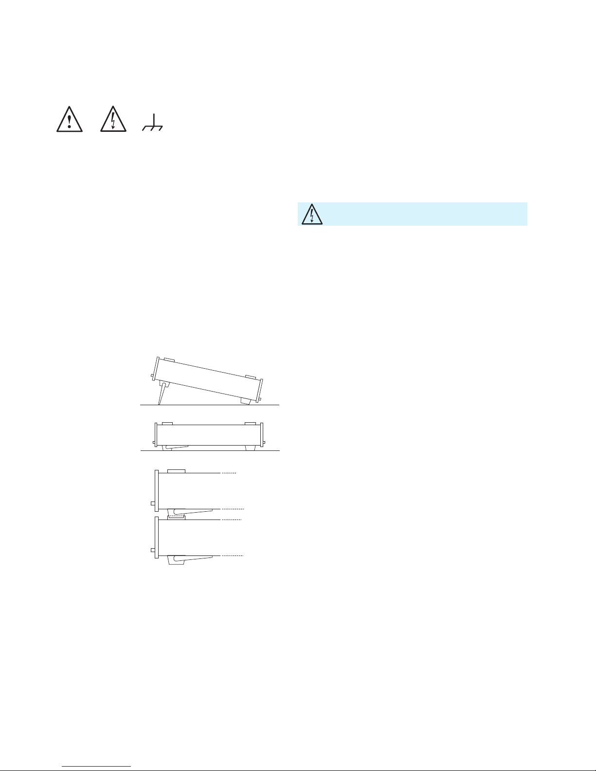
1.3 Setting Up the Instrument
Two positions are possible: .
According to Fig. 1 the front feet are folded down and are
used to lift the instrument so its front points slightly upward (approx. 10 degrees). If the feet are not used (Fig. 2)
the instrument can be stacked safely with many other HAMEG
instruments. In case several instruments are stakked (Fig. 3) the feet rest in the recesses of the instrument
below so the instruments can not be inadvertently moved. Please do not stack more than 3 instruments. A higher stack will become unstable, also heat dissipation may
be impaired.
Fig. 1
Fig. 2
Fig. 3
1.4 Safety
This instrument was built in compliance with VDE 0411
part 1, safety regulations for electrical measuring instruments, control units and Iaboratory equipment. It has
been tested and shipped from the plant in safe condition.
It is in compliance with the regulations of the European
standard EN 61010-1 and the international standard IEC
61010-1. To maintain this condition and to ensure safe operation, the user must observe all instructions and warnings given in this operating manual. Casing, chassis and
all measuring ports are connected to a protective earth
conductor. The instrument is designed in compliance with
the regulations of protection class 0.
For safety reasons, the instrument may only be operated
with authorized safety sockets. The power cord must be
plugged in before signal circuits may be connected. Never
use the product if the power cable is damaged. Check regularly if the power cables are in perfect condition. Choose
suitable protective measures and installation types to ensure that the power cord cannot be damaged and that no
harm is caused by tripping hazards or from electric shock,
for instance.
If it is assumed that a safe operation is no longer possible,
the instrument must be shut down and secured against
any unintended operation.
Safe operation can no longer be assumed:
❙ If the measuring instrument shows visible damage
❙ If the measuring instrument no longer functions properly
❙ After an extended period of storage under unfavorable
conditions (e.g. outdoors or in damp rooms)
❙ After rough handling during transport (e.g. packaging that
does not meet the minimum requirements by post ofce,
railway or forwarding agency).
In case of doubt the power connector should be checked
according to DIN VDE 0100/610:
❙ Only qualied personnel may open the instrument
❙ Prior to opening the instrument must be disconnected
from the line and all other inputs/outputs.
1.5 Intended Operation
The measuring instrument is intended only for use by personnel familiar with the potential risks of measuring electrical quantities. For safety reasons, the measuring instrument may only be connected to properly installed safety
socket outlets. Separating the grounds is prohibited. The
power plug must be inserted before signal circuits may be
connected. The product may be operated only under the
operating conditions and in the positions specied by the
manufacturer, without the product’s ventilation being ob-
structed. If the manufacturer’s specications are not observed, this can result in electric shock, re and/or serious
personal injury, and in some cases, death. Applicable local
It is prohibited to disconnect the earthed protective
connection inside or outside the instrument!
Page 5

41
Important Notes
or national safety regulations and rules for the prevention
of accidents must be observed in all work performed.
The measuring instrument is designed for use in the following sectors: Industry, residential, business and commercial areas and small businesses.
The measuring instrument is designed for indoor use only.
Before each measurement, you need to verify at a known
source if the measuring instrument functions properly.
1.6 Ambient Conditions
The allowed operating temperature ranges from +5°C to
+40 °C (pollution category 2). The maximum relative hu-
midity (without condensation) is at 80%. During storage
and transport, the temperature must be between -20 °C
and +70 °C. In case of condensation during transportation
or storage, the instrument will require approximately two
hours to dry and reach the appropriate temperature prior
to operation. The measuring instrument is designed for
use in a clean and dry indoor environment. Do not operate
with high dust and humidity levels, if danger of explosion
exists or with aggressive chemical agents. Any operating
position may be used; however adequate air circulation
must be maintained. For continuous operation, a horizontal
or inclined position (integrated stand) is preferable.
The maximum operating altitude for the instrument is
2000 m. Specications with tolerance data apply after a
warm up period of at least 30 minutes at a temperature of
23 °C (tolerance ±2 °C). Specications without tolerance
data are average values.
1.7 Warranty and Repair
Our instruments are subject to strict quality controls. Prior
to leaving the manufacturing site, each instrument undergoes a 10-hour burn-in test. This is followed by extensive
functional quality testing to examine all operating modes
and to guarantee compliance with the specied technical
data. The testing is performed with testing equipment that
is calibrated to national standards. The statutory warranty
provisions shall be governed by the laws of the country
in which the product was purchased. In case of any complaints, please contact your supplier.
Use the measuring instrument only with original HAMEG measuring equipment, measuring cables and power cord. Never use inadequately measured power cords. Before each measurement,
measuring cables must be inspected for damage and replaced if
necessary. Damaged or worn components can damage the instrument or cause injury.
To disconnect from the mains, the low-heat device socket on the
back panel has to be unplugged.
The product may only be opened by authorized and
qualied personnel. Prior to working on the product or
before the product is opened, it must be disconnected
from the AC supply network. Otherwise, personnel will
be exposed to the risk of an electric shock.
Any adjustments, replacements of parts, maintenance and
repair may be carried out only by authorized technical personnel. Only original parts may be used for replacing parts
relevant to safety (e.g. power switches, power transformers, fuses). A safety test must always be performed after
parts relevant to safety have been replaced (visual inspection, PE conductor test, insulation resistance measurement,
leakage current measurement, functional test). This helps
ensure the continued safety of the product.
1.8 Maintenance
The display may only be cleaned with water or an
appropriate glass cleaner (not with alcohol or other
cleaning agents). Follow this step by rubbing the display
down with a dry, clean and lint-free cloth. Do not allow
cleaning uid to enter the instrument. The use of other
cleaning agents may damage the labeling or plastic and
lacquered surfaces.
1.9 Line fuse
The instrument has 2 internal line fuses: T 0.8 A. In case of
a blown fuse the instrument has to be sent in for repair. A
change of the line fuse by the customer is not permitted.
1.10 Power switch
The instrument has a wide range power supply from 105
V to 253 V, 50 Hz or 60 Hz ±10 %. There is hence no line
voltage selector.
Fuse type:
Size 5 x 20 mm; 250V~, C; IEC 127, Bl. III; DIN 41 662 (possibly DIN 41 571, Bl. 3). Slow-blow (T) 0,8A.
1.11 Batteries and Rechargeable Batteries/Cells
1. Cells must not be disassembled, opened or crushed.
2. Cells and batteries may not be exposed to heat or re.
Storage in direct sunlight must be avoided. Keep cells
and batteries clean and dry. Clean soiled connectors
using a dry, clean cloth.
Clean the outer case of the measuring instrument at regular intervals, using a soft, lint-free dust cloth.
Before cleaning the measuring instrument, please make sure that
it has been switched off and disconnected from all power supplies (e.g. AC supply network).
No parts of the instruments may be cleaned with chemical cleaning agents (such as alcohol, acetone or cellulose thinner)!
If the information regarding batteries and rechargeable batteries/
cells is not observed either at all or to the extent necessary, product users may be exposed to the risk of explosions, re and/or serious personal injury, and, in some cases, death. Batteries and rechargeable batteries with alkaline electrolytes (e.g. lithium cells)
must be handled in accordance with the EN 62133 standard.
Page 6

42
Important Notes
3. Cells or batteries must not be short-circuited. Cells or
batteries must not be stored in a box or in a drawer
where they can short-circuit each other, or where they
can be short-circuited by other conductive materials.
Cells and batteries must not be removed from their
original packaging until they are ready to be used.
4. Keep cells and batteries out of reach of children. Seek
medical assistance immediately if a cell or battery was
swallowed.
5. Cells and batteries must not be exposed to any me-
chanical shocks that are stronger than permitted.
6. If a cell develops a leak, the uid must not be allowed
to come into contact with the skin or eyes. If contact
occurs, wash the affected area with plenty of water
and seek medical assistance.
7. Improperly replacing or charging cells or batteries can
cause explosions. Replace cells or batteries only with
the matching type in order to ensure the safety of the
product.
8. Cells and batteries must be recycled and kept separate
from residual waste. Cells and batteries must be recycled and kept separate from residual waste. Rechargeable batteries and normal batteries that contain lead,
mercury or cadmium are hazardous waste. Observe
the national regulations regarding waste disposal and
recycling.
1.12 Product Disposal
The Electrical and Electronic Equipment Act implements
the following EG directives:
❙ 2002/96/EG (WEEE) for electrical and electronic
equipment waste and
❙ 2002/95/EG to restrict the use of certain hazardous
substances iin electronic equipment (RoHS directive).
❙
Once its lifetime has ended, this product should be disposed of separately from your household waste. The disposal at municipal collection sites for electronic equipment is also not permitted. As mandated for all manufacturers by the Electrical and Electronic Equipment Act (ElektroG), ROHDE & SCHWARZ assumes full responsibility for
the ecological disposal or the recycling at the end-of-life of
their products.
Please contact your local service partner to dispose of the
product.
Fig. 1.4: Product labeling in accordance
with EN 50419
Page 7
43
Description of the Operating Elements
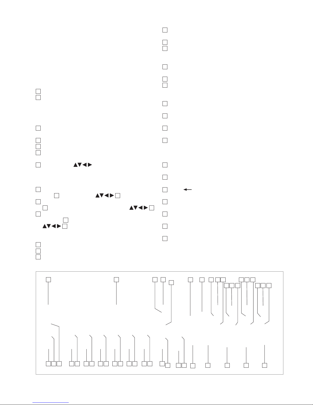
Fig. 2.1: Front panel of HM8118
2 Description of
the Operating
Elements
Front panel of H M 8118
1
POWER – Turning on/off the instrument
2
DISPLAY (LCD) – Display of measurement results and
units, ranges, frequencies, level, equivalent circuit,
functions and parameters
MENU
3
SELECT – Opening the submenus SETUP, CORR, SYST
and BIN (only with installed Binning Interface HO118)
4
ENTER – Conrmation of input values
5
ESC – Cancel the menu function
6
Rotary knob (Knob/Pushbutton) – Selection of func-
tions and parameters
7
Arrow buttons – Pushbuttons for parameter
selection
SET
8
FREQ – Setting of the test signal frequency with rotary
knob 6 or arrow buttons
7
9
LEVEL – Setting of the test signal level with rotary knob
6
and cursor position with arrow buttons
7
10
BIAS – Setting of the bias voltage or current with ro-
tary knob
6
and cursor position with arrow buttons
7
ZERO
11
OPEN – Activating the OPEN calibration
12
SHORT – Activating the SHORT calibration
13
LOAD – Activating the LOAD calibration
MODE
14
AUTO – Activating the automatic selection of equiva-
lent circuit
15
SER – Activating the series equivalent circuit
16
PAR – Activating the parallel equivalent circuit
RANGE
17
AUTO/HOLD – Activating the automatic measurement
range (LED lights up) or the range HOLD function
18
UP – Range up
19
DOWN – Range down
Connectors
20
L CUR (BNC socket) – Low Current; signal output for
series measurements (signal generator)
21
L POT (BNC socket) – Low Potential; signal input for pa-
rallel measurement (voltage measurements)
22
H POT (BNC socket) – High Potential; signal input / out-
put for parallel measurements (measurement bridge)
23
H CUR (BNC socket) – High Current; signal input for se-
ries measurements (current measurements)
Instrument functions
24
BIAS MODE/ESC – Activating of internal / external bias
voltage resp. cancelling the editing mode (ESC)
25
TRIG MODE/ENTER – Changing the trigger mode resp.
conrming an input value
26
BIAS / – Activating the bias voltage resp. erasing
the last character of an numeric input
27
TRIG / UNIT – Single trigger in manual trigger mode
resp. selection of a parameter unit
28
AUTO / 6 – Activating the automatic measurement
function resp. entering numeric value 6
29
M / – – Selection of the measurement function „Mutual
Inductance“ resp. parameter input of the character „-“.
30
R-Q / 5 – Selection of the measurement function ‘Resis-
tance‘ R und ‘Quality factor‘ Q resp. entering numeric
value 5
1 2 4 3
5
6 7 9 8 10
12 11 13
15 14 16
18 17 19
22 21
20
24
43
232526
27282930313233343536373839424041
Page 8
44
Description of the Operating Elements
Fig. 2.2: Back panel of HM8118
47 48
45
4446
49
31
N-Θ / . – Selection of the measurement function ‘Turns
ratio‘ N and ‘Phase angle‘ Θ resp. parameter input of
the character “. “
32
C-R / 4 – Selection of the measurement function ‘Ca-
pacitance‘ C and ‘Resistance‘ R resp. entering numeric
value 4
33
G-B / 0 (Pushbutton)
Selection of the measurement function ‘Conductance‘
G and ‘Susceptance‘ B resp. entering numeric value 0
34
C-D / 3 – Selection of the measurement function ‘Capa-
citance‘ C and ‘Dissipation factor‘ D resp. entering numeric value 3
35
R-X / 9 – Selection of the measurement function ‘Resis-
tance‘ R and ‘Reactance‘ X resp. entering numeric value 9
36
L-R / 2 – Selection of the measurement function ‘Induc-
tance‘ L and ‘Resistance‘ R resp. entering numeric value 2
37
Y-Θ / 8 – Selection of the measurement function ‘Ad-
mittance‘ Y and ‘Phase angle‘ Θ resp. entering numeric
value 8
38
L-Q / 1 – Selection of the measurement function ‘Induc-
tance‘ and ‘Quality factor‘ Q resp. entering numeric value 1
39
Z-Θ / 7 – Selection of the measurement function ‘Im-
pedance‘ Z and ‘Phase angle‘ Θ resp. entering numeric
value 7
40
DISPLAY MODE – Toggling the display of measurement
values with / without parameters
41
RECALL / STORE – Loading/storing of instrument
settings
42
REMOTE / LOCAL – Toggling between front panel (LO-
CAL) or remote operation (LED lights up); if local lockout was activated, the instrument can not be operated
from the front panel.
43
Ground (4 mm socket) – Ground connector ( ). The so-
cket is directly connected to the mains safety ground!
Back panel of HM8118
44
TRIG. INPUT (BNC socket) –
Trigger input for external trigger
45
BIAS FUSE (Fuse holder) –
Fuse for external voltage input ext. BIAS
46
EXT. BIAS (4 mm safety sockets) –
External bias input (+, –)
47
INTERFACE – HO820 Dual Interface USB/RS-232 (gal-
vanically isolated) is provided as standard
48
BINNING INTERFACE (25 pin D-Sub socket) –
Output to control external binning sorters for components (option HO118)
49
POWER INPUT (Power Cord Receptacle)
Page 9

45
Introduction
3 Introduction
3.1 Requirements
❙ HAMEG HM8118 LCR measuring bridge with rmware
from 1.37 upwards.
❙ HZ184 Kelvin measurement cables
❙ 1 x HAMEG 1,000 µF capacitor (not contained in
shipment)
❙ 1 x HAMEG 280 µH inductor (not contained in shipment)
❙ 1 x HAMEG 100 kΩ resistor (not contained in shipment).
First connect the HZ184 cables supplied to the HM8118.
The two plugs of the black cable are connected to the terminals LCUR and LPOT, the plugs of the red cable to the
terminals HCUR and HPOT.
After turning the instrument on, the rst steps are the open
circuit and the short circuit calibration procedures at the
preselected frequency of 1.0 kHz because the measurement cables HZ184, in conjunction with the terminals, due
to their design, show a stray capacity, a residual inductance and a residual resistance which impair the accuracy
of the measurement results. In order to minimize these in-
uences, the compensation of impedance measurement
errors caused by adapters and cables is necessary.
For the open circuit calibration, position the two clips apart
from each other. For the short circuit calibration connect
both clips as shown in Fig. 3.1.
Push the button MENU/SELECT
3
and then the button
C-D
34
in order to enter the CORR menu. Select the menu
item MODE and use the knob
6
to change the menu entry
from SGL to ALL in order to automatically perform the calibration at all 69 frequency steps provided. Leave the menu
by pushing the button MENU/ESC
5
.
The following components are only intended to be used as an example for a quick introduction to the instrument.
Fig. 3.1: Short circuit calibration with HZ184.
The mode SGL is used to only calibrate at the presently selected
frequency; this procedure takes just a few seconds and is destined for measurements in one or a few frequency ranges only.
Now start the open and short circuit calibrations by
pushing the buttons ZERO/OPEN
11
resp. ZERO/SHORT
12
. The instrument will now determine correction factors
at all 69 frequency steps valid for the presently connected
measurement cables and store them until the instrument is
switched off. This procedure will last appr. 2 minutes.
3.2 Measurement of a capacitor
Now connect the capacitor to the terminals of the HZ184.
Please observe the polarity of the capacitor and connect
the black terminal to the negative terminal of the capacitor,
marked with a – (minus).
As the instrument is set to automatic mode, the measurement function will be automatically switched to function
no. 3 (C-D). Because the measuring frequency of 1.0 kHz
was preselected, the capacitor will not be measured in its
regular operating mode, so the value displayed of appr.
900 µF will not equal the specied value of 1,000 µF.
Change the measuring frequency to 50 Hz by pushing the
button SET/FREQ
8
and turning the knob until 50 Hz are
shown on the display. Now the value displayed will change
to appr.1,000 µF depending on its tolerance. The dissipation factor „D“ will be very low at this setting.
The smaller the loss angle, the more the real world components will come close to the ideal. An ideal inductor has
a loss angle of zero degrees. An ideal capacitor also has
a loss angle of zero degrees. An ideal electrical resistor,
however, has a loss angle of 90 degrees, it has no capacitive or inductive components.
3.3 Measurement of an inductor
Before you connect the choke, increase the measuring frequency by one decade to 500 Hz by pushing the arrow
button 7 above the knob. Disconnect the capacitor and
connect the choke to the terminals of the HZ184.
The instrument will now automatically switch to the function no. 1 (L-Q) and the inductance of the choke will be dis-
|Z| = 1000
Ω
Q = 500
D = 0,002
Q = 500
D = 0,002
D = 500
Q = 0,002
D = Q = 1
D = Q = 1
R
jX
D = 500
Q = 0,002
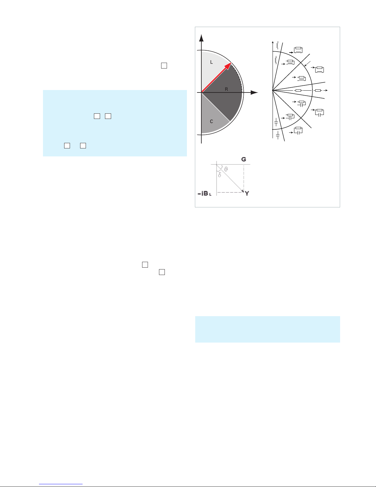
Fig. 3.2: HM8118 measurement principle, left: schematic, right: detailled
presentation.
Imaginary
Axis
below -- 45° = C
above 45° = L
Real
Axis
phase angle
Page 10

46
Introduction
played. The value should be appr. 280 µH. As shown in Fig.
3.2, the phase angle of an inductor must be in the range
of + 45 to 90°. In order to prove this, leave the automatic
mode by pushing the button „Z-Θ
39
. The phase angle displayed will be appr. +70° and depends on the measuring
frequency set.
For comparison: the phase angle of the capacitor measured before is appr. -87° at 50 Hz.
3.4 Measurement of a resistor
Disconnect the choke and connect the 100 kΩ resistor supplied. As the instrument was previously set manually to the
function Z-Θ, the value of its impedance can be directly
read (appr. 100 kΩ). As decribed on the page before, an
ideal resistor has no capacitive or inductive components.
Hence the phase resp. loss angle of the component connected is close to zero degrees.
The HM8118, upon connection of the resistor, automatically changed the internal equivalent circuit from series
connection SER to parallel connection PAR (LED pushbuttons
15
and 16). If the automatic selection of the equivalent
circuit was chosen (pushbutton AUTO
14
), the LCR measuring bridge will automatically select the equivalent circuit
which, depending on the component connected, is best
suited to yield a precise measurement result. The equivalent circuit represents the measurement circuit. Usually,
components with a low impedance (capacitors, chokes)
will be measured using the series connection equivalent
circuit while components with a high impedance (e.g. resistors) will be measured using the parallel
equivalent circuit.
4 First-Time Ope-
ration
4.1 Connecting the instrument
Prior to connecting the instrument to the mains, check
whether the mains voltage conforms to the mains voltage
range specied on the rear panel. This instrument has a
wide-range power supply and hence requires no manual
setting of the mains voltage.
The fuse holder of the BIAS FUSE
45
, i.e. the external BIAS
input, is accessible on the rear panel. Prior to exchanging a
fuse the instrument must be disconnected from the mains.
Then the fuse holder may be removed with a suitable
screw driver, using the slot provided. Afterwards the fuse
can be removed from the holder and exchanged. The holder is spring-loaded and has to be pushed in and turned.
It is prohibited to use „repaired“ fuses or to short-circuit
the fuse. Any damages incurred by such manipulations will
void the warranty. The fuse may only be exchanged by this
type:
Fuse with ceramic body, lled with re extinguishing
material:
Size 6.3 x 32 mm; 400 VAC, C; IEC 127, Bl. III; DIN 41 662
(alternatively DIN 41 571, p. 3), (F) 0,5 A
4.2 Turning on the instrument
Prior to operating the instrument for the rst time, please be sure to observe the safety instructions mentioned
previously!
The LCR bridge is switched on by using the power switch
1
. Once all keys have briey been illuminated, the bridge
can be operated via keys and the knob on the front panel. If the keys and the display do not light up, either the
mains voltage is switched off or the internal input line fuses are defective. The current measurement results are
Fig. 4.1: Power Input
Fig. 4.2: Rear panel with fuse
Page 11
47
First-Time Operation
shown in the right panel and the essential parameters in
the left panel of the display. The four BNC sockets located
on the front panel can be connected to the component to
be measured with the appropriate measuring accessories.
Additionally, it is also possible to connect the measuring
instrument via ground socket on the front panel
43
with
ground potential. The socket is suitable for a banana plug
with a 4 mm diameter.
If there are undened messages on the display or if the instrument fails to react to operation of its controls turn it
off, wait a minute and turn it on again in order to trigger a
reset operation. If the display remains unchanged or operation impossible, turn it off and take it to a qualied service point (see Safety Instructions).
4.3 Line frequency
Prior to rst measurements, the line frequency setting
must be set to the applied line frequency, 50 or 60 Hz. If
the line frequency is not set properly, depending on the
measurement range and the line frequency value, instabilities may occur e.g. on the display. In order to set the
line frequency press the SELECT button
3
, use the SYST
menu for accessing MAINS FRQ, use the knob
6
for se-
lecting the correct value.
4.4 Measurement Principle
The LCR meter HM8118 is not a traditional Wien, Maxwell
or Thomson measurement bridge. Rather, when connecting a test object, the impedance |Z| and the correspon-
ding phase angle Θ (phase between current and voltage)
are always determined (see g. 4.3). These measurement
values are frequency dependent and will be determined
by means of an AC test signal (which can be set manually
between 50mV and 1.5V). The test signal is induced in the
test item. This distinguishes a LCR bridge from a multimeter (DC measurement). Based on the measurement principle, the measured impedance is always essential. Based
on the impedance (X axis) and the phase angel (angle), the
instrument is able to determine the missing value of the
Y axis. This means that it is not the DC component that is
being measured but rather the AC value. The issued values
are calculated digitally. This measurement of impedance
and phase angle is subject to a certain measurement inaccuracy which will be described on the following pages.
In general, the HM8118 bridge can only determine the
ESR, ESC or ESL (= Equivalent Series Resistance / Capacity / Inductivity) according to the equivalent circuit dia-
The front panel ground connector and the ground contact of the
trigger input are directly connected to the mains safety ground
potential through the line cord. The outer contacts of the front
panel BNC connectors
20
– 23 (as well as the shields of any coaxial cables attached) are connected to the GUARD potential
which has no connection to the safety ground! No external voltages may be applied to the BNC connectors! The rear panel interfaces
47
and 48 are galvanically isolated (no connection to
ground)!
gram of the component and is primarily used to measure
individual components. If a circuit with multiple components is connected to the bridge, the instrument will always determine the ESR, ESC or ESL of the entire circuit
/ component group. This can potentially skew the measurement result. The connected component / circuit is assumed to be the „Black Box“. These values are available for
each component; however, please keep in mind that these
always describe the result of multiple, possibly overlapping
individual capacities, inductances and impedances. This
can easily cause some misunderstandings especially with
coils (magnetic eld, eddy currents, hysteresis, etc.)
Fig. 4.4 shows the link between capacity C
s
(or resistance
R
s
) and various test voltages that can be selected with the
bridge (0.2V
eff
to 1.5 V
eff
). As can be seen in the gure, the
measurement values of C
s
or Rs are highly dependent on
the selected test voltage. Point A shows the test point of
the instrument during the measurement of a single component, point B shows the test point during the measurement of a component group (in this case two capacities connected in parallel). In contrast to test point A, with
point B the bridge switches the measurement range due
to the impedance of the entire component group. As a result, the measurement results for point A and point B are
different.
The LCR bridge HM8118 is primarily intended to determine passive components. Therefore, it is not possible to determine test
objects which are externally supplied with power.
|Z| = 1000
Ω
Q = 500
D = 0,002
Q = 500
D = 0,002
D = 500
Q = 0,002
D = Q = 1
D = Q = 1
R
jX
D = 500
Q = 0,002
Imaginary
Axis
below -- 45° = C
above 45° = L
Real
Axis
phase angle
Q = Quality factor
D = Loss tangent
D = 1 / Q
Q = 1 / D = 1 / tan delta
(delta = Opposite angle of the phase angle)
Fig. 4.3: Measurement principle
Page 12

48
First-Time Operation
selected for this DUT, it will display in the center of the se-
lected range. Since the measurement error is dened as
a percentage of the measurement range nal value, the
measurement error in the higher range goes up nearly by
a factor of 2. Typically, the measurement error is increased
accordingly in the nearest higher measurement range. If a
component is removed from the test lead or measurement
adapter during a measuring process in the continuous
measurement mode, the automatically selected measurement range and the automatically selected measurement
function can be adopted by switching to the manual measurement range selection (RANGE HOLD). This allows the
measurement time during the measurement of many similar components to be reduced.
4.5.1 Example of determining the measurement
accuracy
The accuracy calculation is always based on the data sheet
table (see g. 4.5). To calculate the corresponding measurement accuracy, the following component parameters are
required (component operating point):
❙ Component impedance at corresponding measurement
frequency
❙ The measurement frequency.
As an example, a 10 pF capacitator with an impedance of
15 MΩ at 1 kHz will be measured. In this case, the top row
of the accuracy table is valid:
The accuracy decreases with the measurement voltage (test voltage) because the signal / noise ratio decreases. Consequently,
this leads to additional instabilities. The accuracy decreases at
the same rate. If 0.5V is used as measurement voltage, for instance, the base accuracy is one half.
Impedance: 100 MΩ
4 MΩ
20
Hz
1
kHz
10
kHz
100
kHz
0,2% + I
Z I / 1,5 GΩ
The actual measured series resistance includes all series
resistances such as the component leads and the resistance of series-connected foils in capacitors as well as dielectric losses; it is expressed by the dissipation factor DF.
The equivalent series resistance (ESR) is frequency-dependent according to the formula:
ESR = Rs = D/ωCs
where ω „Omega“ = 2 π f (circular frequency) represents.
Traditionally, the inductance of coils is measured in a series
circuit; however there are cases where a parallel circuit will
yield a better representation of the component. In small
„air“ coils mostly the ohmic or copper losses are predominant , hence the series circuit is the proper representation.
The core of coils with an iron or ferrite core may contribute
most of the losses, the parallel circuit is to prefer here.
4.5 Measurement Accuracy
The measurement of impedance and phase angle is prone
to a certain amount of inaccuracy. The measurement accu-
racy of a specic test point can be calculated based on the
accuracy table in the data sheet (see g. 4.5). Make sure
you know the impedance of the corresponding component
at the respective test point. No further information is requi-
red to calculate the accuracy. The base accuracy of 0.05%
as indicated in the data sheet pertains only to the base accuracy of the HM8118 bridge. The base accuracy only indicates the general measurement uncertainty of the instrument. The accuracy table describes the measurement accuracy that additionally has be taken into account.
The highest accuracy is ensured when the DUT value (=
Device Under Test) is approximately centered in the measurement range. If the next highest measurement range is
Fig. 4.4: Example correlation Cs (or Rs) and test voltage
The resistance measurement always occurs in compliance with
the method to apply voltage (AC) and measure the resulting current. The only difference to L or C is that the phase angle is nearly 0° (real resistance). A resistance measurement with DC is
not intended.
Fig. 4.5: Table to determine the accuracy
Impedance: 100 MΩ
4 MΩ
1 MΩ
25 kΩ
100 Ω
2.5 Ω
0,01 mΩ
20 Hz 1 kHz 10 kHz 100 kHz
0.2% + I Z I / 1.5 GΩ
0.05% +
I Z I / 2 GΩ
0.1% +
I Z I / 1,5 GΩ
0.5% +
I Z I / 100 MΩ
0.2% +
I Z I / 100 MΩ
0.1% + 1 mΩ / I Z I
0.3% + 1 mΩ / I Z I
0.2% +
2 mΩ / I Z I
0.5% +
2 mΩ / I Z I
0.5% +
5 mΩ / I Z I
+
I Z I / 10 MΩ
Page 13

49
Setting of Parameters
The values of the component set in into the formula:
The units will be adjusted once the component values
have been entered and the formula has been calculated
because the second addend is without unit:
For the 10pF component this leads to:
1.2% of 10pF is 0.12pF.
Based on the calculation the displayed value will be between 10pF - 0.12pF = 9.88pF and 10pF + 0.12pF = 10.12pF.
15 MΩ
Accuracy
@1kHz
= 0,2% +
1,5 GΩ
15 x 10
6
Ω
Accuracy
@1kHz
= 0,2% +
1,5 x 10⁹ Ω
15 Ω
Genauigkeit
@1kHz
= 0,2% +
1,5 x 10³ Ω
15 Ω
Genauigkeit
@1kHz
= 0,2% +
1500 Ω
Genauigkeit
@1kHz
= 0,2% + 0,01
Accuracy
@1kHz
= 0,2% + 0,01 = 0,2 + (0,01 x 100%) = 0,2% + 1% = 1,2%
5 Setting of
Parameters
5.1 Selecting Values /Parameters
Each function and operating mode of the measuring instrument can be selected with the keys on the front panel
of the instrument. Use the respective function key to select the measurement function. An active measurement
function is highlighted by an illuminated white LED. Subsequent settings refer to the selected measurement function.
To set parameters, three options are available:
❙ Numeric keypad
❙ Knob
❙ Arrow keys
You can set the measuring instrument parameters by pressing the SELECT key
3
and by using the menu functions
SETUP, CORR, SYST and BIN (will only be displayed with
an integrated binning interface HO118). Use the keys L-R/2
36
, C-D/3 34, C-R/4 32, R-Q/5 30 to select the sub menus
associated with the menu functions. Depending on the
function, you can set the respective measuring instrument
parameters by using the arrow keys
7 and the
knob
6
. Pressing the knob allows the user to modify the
corresponding measuring instrument parameters. This will
be indicated in the display by a blinking „E“ (Edit).
5.1.1 Knob with Arrow Keys
If you select the respective menu via arrow keys, you can
press the knob to activate the editing mode. If the editing
mode is active (blinking „E“ on the display), you can use
the knob to select the parameter or the input value. The
value input will be modied gradually, and the respective
input parameter will be set instantly. The nominal value is
increased by turning the knob to the right, and it is decreased by turning it to the left. Press the knob again to deacti-
vate the editing mode and to conrm the function slection.
Use the arrow keys to select the respective menu function.
5.1.2 Numeric Keypad
The easiest way to enter a value precisely and promptly is
to use the numeric keypad with numeric keys (0...9) and
the decimal point key. Once you have pressed the knob to
activate the editing mode, you can use the SELECT key
3
,
the ENTER key
25
or press the knob again to reactivate the
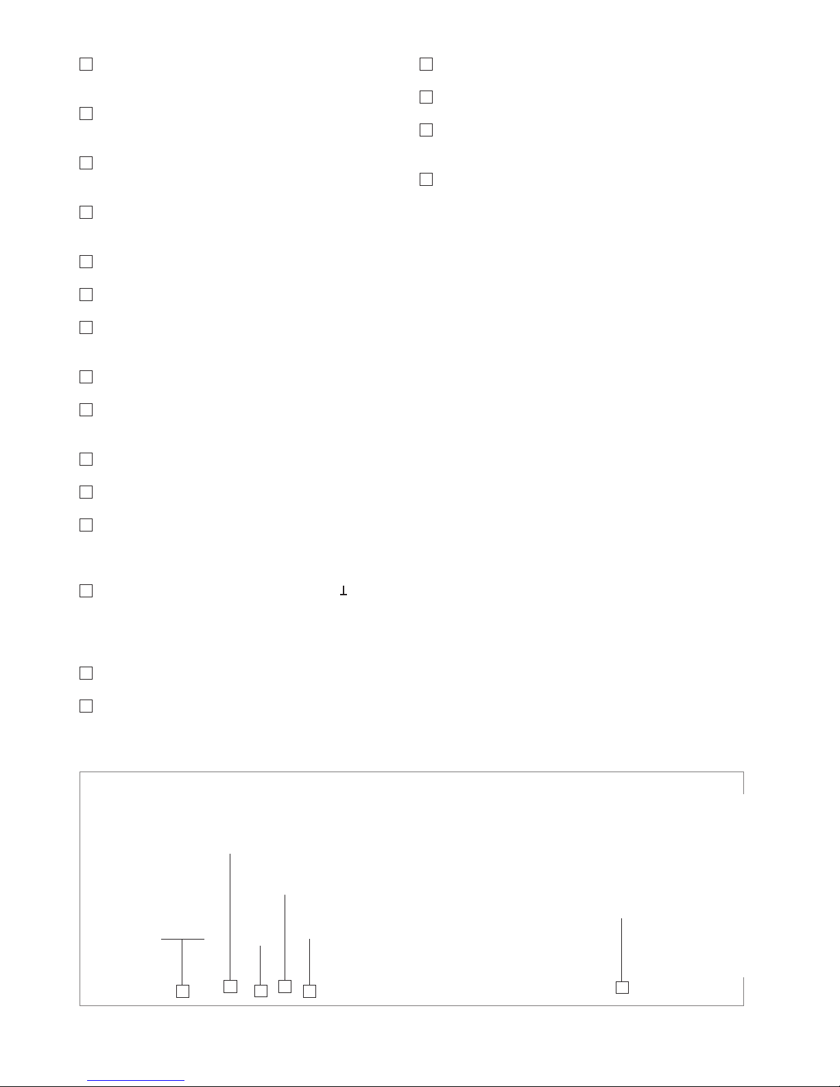
Fig. 5.1: Numeric keypad with function keys
Page 14

50
Setting of Parameters
manual value input via numeric keypad. This opens a value entry window where you can enter the respective value by means of number pads (in addition to the corresponding unit, depending on the measuring instrument pa-
rameter). After entering the value via keypad, conrm the
entry by pressing the ENTER key or by pressing the knob
again. Before conrming the parameter, you can delete the
value that has been entered incorrectly by pressing the
key. The ESC key allows you to cancel the operation to enter parameters. This will close the editing window.
5.2 Selecting the Measurement Function
Out of nine measurement functions, the LCR bridge
HM8118 allows you to measure two parameters simultane-
ously and display them as measurement values. The rst
parameter refers to the „main measurement value display“
and the second parameter to the „secondary measurement value display“. Depending on the connected component, the following main and secondary measurement value displays can be shown:
L-Q
Inductance L and quality factor (quality) Q
L-R
Inductance L and resistance R
C-D
Capacity C and dissipation factor D
C-R
Capacity C and resistance R
R-Q
Resistance R and quality factor (quality) Q
Z-
Θ
Apparent impedance (impedance) Z
and phase angle Θ
Y-
Θ
Admittance Y and phase angle Θ
R-X
Resistance R and reactance X
G-B
Conductance G and susceptance B
N-
Θ
Transformer ratio N and
Phase difference Θ
M
Transformer mutual inductance M
You can select the desired measurement function by pressing the keys
29
to 39.
In the automatic mode (key AUTO), the bridge switches
both the measurement function (key
28
- 39) as well as the
internal equivalent circuit diagram of the measurement circuit appropriately to the measured values to serial (for inductive loads) or to parallel (for capacitive loads).
6 Measurement
Value Display
The values measured with the LCR bridge HM8118 can be
shown on the LCD display in three different versions:
❙ Measurement value
❙ absolute measurement value deviation ∆ ABS or
❙ relative measurement value deviation ∆ % (in percent).
Press the SELECT key
3
to use the SETUP and the setting DEV_M (for the main measurement value display) and
DEV_S (for the secondary measurement value display) to
switch the measurement value display. If you select the
function DEV_M or DEV_S via arrow keys, you can press
the knob to activate the editing mode. If the editing mode
is active (blinking „E“ on the display), you can use the knob
to select the respective measurement value display. Press
the knob again to deactivate the editing mode and to con-
rm the function selection.
The main measurement value and the secondary measurement value will be shown on the display including the decimal point and the associated units. The resolution of the
main measurement value display (L, C, R, G, Z or Y) consists of one, or two or three digits before the decimal point
and four, or three or ve digits after the decimal point. The
resolution of the secondary measurement value display (D,
Q, R, B, X or Θ) consists of one, or two or three digits before the decimal point and four, or three or ve digits af-
ter the decimal point. The depiction OVERRANGE will be
shown on the display if the measurement value is located
outside the set measurement range.
6.1 Relative Measurement Value Deviation ∆ %
(#, %)
The # symbol in front of a measurement value and the %
symbol following a measurement value indicate that the
relative measurement value deviation ∆ % (in percent) of
the measured L, C, R, G, Z or Y measurement value, or of
the D, Q, R, B, X or Θ measurement value of a stored measurement value (reference value) is displayed.
6.2 Absolute Measurement Value Deviation ∆ ABS
(#)
The # symbol in front of a measurement value indicates
that the absolute measurement value deviation ∆ ABS of
the measured value, similarly to ∆ %, of the stored mea-
If the bridge shows a negative value on the display, make sure to
check the measurement frequency, the measurement voltage and
possibly the phase angle of the component. For instance, if the
phase angle of a capacitator is close to 90°, it could result in a
negative display value due to the measurement accuracy. For instance, negative values may occur for coils with cores (erroneous
measurement due to magnetization).
Page 15

51
Setting of Parameters
surement value (reference value) is displayed. The measurement value deviation is shown in the appropriate units
(Ohm, Henry, etc.).
6.3 Reference Value (REF_M, REF_S)
The menu function REF_M or REF_S enables the user
to enter a reference value which will be used as a basis
for the measurement result ∆ % or ∆ ABS. Press the SELECT key
3
to use the SETUP menu function and the setting REF_M (for the main measurement value display) and
REF_S (for the secondary measurement value display) to
enter a reference value each. The applicable units will be
selected automatically depending on the selected measurement function for the main measurement value display
(H, F, Ω or S) or for the secondary measurement value display (Ω, S or °). You can enter a reference value numerically
with up to ve digits after the decimal point. Alternatively,
you can press the TRIG key
27
to perform a measurement,
and the resulting measurement value will be adopted as
reference value.
6.4 Selecting the Measurement Range
The measurement range can be selected automatically or
manually. In some cases, it is useful to lock the automatic measurement range function as it can take a complete
measurement cycle to determine the appropriate measurement range. This can also be useful when switching similar
components. The bridge HM8118 automatically switches
to the measurement range 6 and subsequently back to the
adequate measurement range if a component has been
connected to the instrument. If the automatic measurement range function has been locked and the impedance
of a component equals more than 100 times the nominal
value of the measurement range, the bridge will display an
OVERRANGE measurement error. In this case, it is necessary to select a suitable measurement range for the measurement. Press the AUTO/HOLD key
17
to switch between the automatic and the manual measurement range
selection.
6.4.1 Automatic range selection (AUTO)
If the automatic measurement range function is activated,
the bridge automatically selects the most suitable measurement range for an exact measurement in accordance
with the connected component. The instrument will switch
to the next measurement range level below if the measure-
ment value is smaller than 22.5% of the selected measurement range or 90% higher than the end value of the mea-
surement range. An integrated switching hysteresis of ap-
proximately 10% prevents the instrument from constantly
switching the measurement range if the measurement value is close to the switching threshold of a measurement
range. The following table shows the switching thresholds
for switching the measurement range (if the constant voltage CST V is switched off):
Measurement Range Component Impedance
1 to 2 Z > 3.00 Ω
2 to 3 Z > 100.00 Ω
3 to 4 Z > 1.60 kΩ
4 to 5 Z > 25.00 kΩ
5 to 6 Z > 1.00 MΩ
2 to 1 Z < 2.70 Ω
3 to 2
Z < 90.00 Ω
4 to 3
Z < 1.44 kΩ
5 to 4
Z < 22.50 kΩ
6 to 5
Z < 900.00 kΩ
6.4.2 Manual Measurement Range Selection
The bridge HM8118 includes 6 measurement ranges (1–6).
The measurement ranges can be preselected manually or
automatically. The following table indicates the source resistance and the impedance of the connected component
for each measurement range. The specied ranges are impedance ranges, not resistance ranges. Capacitators or inductances are frequency-dependent components.
Measurement range
Source
Impedance
Component
Impedance
1 25.0 Ω 10.0 µΩ bis 3.0 Ω
2 25.0 Ω 3.0 Ω bis 100.0 Ω
3 400.0 Ω 100.0 Ω bis 1.6 kΩ
4 6.4 kΩ 1.6 kΩ bis 25.0 kΩ
5 100.0 kΩ 25.0 kΩ bis 2.0 MΩ
6 100.0 kΩ 2.0 MΩ bis 100.0 MΩ
Additionally, the impedance of capacitators is inversely
proportionate to the frequency. Therefore, larger capacitators will be measured in the lower impedance measurement ranges. Consequently, the measurement range for
any given component may change as the measurement
frequency changes. If you wish to measure multiple similar components, it is possible to shorten the measurement time by using the AUTO/HOLD
17
key to switch from
the automatic measurement range selection to the manual
measurement range selection with the DUT (= Device Under Test) connected. The AUTO/HOLD key will no longer
be illuminated. It is recommended to primarily use the ma-
During the measurement of an inductance in the AUTO mode, it
may occur that the HM8118 is constantly changing the measurement range. This is based on the fact that the source impedance
is dependent on the selected measurement range so that after
switching the measurement range, the newly measured value is
outside the range of the 10% hysteresis. In this case, it is recommended to use the manual measurement range selection.
The LCR bridge HM8118 does not create a 50Ω system. Instead,
it changes its internal resistance dependent on measurement
function and measurement range. Every cable shows losses and
distorts the original measurement result because of inductive and
capacitive properties (particularly because of its length).
The input impedance changes dependent on the selected
measurement range and the connect load impedance between
25Ω and 100kΩ.
Page 16

52
Instrument Functions
nual measurement range selection for high-precision measurements to prevent potential measurement errors due to
incorrect use and other uncertainties. Whenever possible,
make sure to perform measurements with the automatic
measurement range selection activated.
Use the function RNG in the SETUP menu to activate the
manual measurement range selection. Press the knob to
activate the editing mode. You can then press the knob
to select the manual measurement range. If the manual
measurement range selection is activated, you can use the
UP
18
key to manually switch to a higher measurement
range. Press the DOWN
19
key to manually switch to a lo-
wer measurement range.
6.5 Circuit Type
If the automatic circuit type selection is activated (by pressing the AUTO
14
key), the LCR bridge HM8118 will automatically select the circuit type (serial or parallel) that is
best suited for the precise measurement, according to the
connected component. It is also possible to select the circuit type manually (by pressing the SER
15
key for serial, or
by pressing the PAR
16
key for parallel).
The circuit type displays the equivalent circuit diagram of
the measurement circuit. Typically, the inductance of coils
is measured in serial mode. However, for certain situations
the parallel equivalent circuit diagram may be better suited
to measure physical components. For instance, this is the
case for coils with iron core which most signicantly experience core losses. If the most signicant losses are ohmic
losses or losses in the connecting wires of wired components, a serial circuit would be better suited as equivalent
circuit diagram for the measurement circuit. In the automatic mode, the bridge selects the serial equivalent circuit
diagram for impedances below 1kΩ and the parallel equivalent circuit diagram for impedance above 1kΩ.
7 Instrument
Functions
Press the SELECT key to open the main menu. The main
menu enables you to access the submenus SETUP, CORR
and SYST via numeric keypad.
7.1 SETUP Menu
7.1.1 Measurement Frequency FRQ
The LCR bridge HM8118 includes a measurement frequency range from 20 Hz to 200 kHz (in 69 increments)
with a base accuracy of 100 ppm. The 69 increments of the
measurement frequency range are as follows:
Measurement Frequencies
20Hz 90Hz 500Hz 2.5kHz 12kHz 72kHz
24Hz 100Hz 600Hz 3.0kHz 15kHz 75kHz
25Hz 12 0Hz 720Hz 3.6kHz 18kHz 80kHz
30Hz 150Hz 750Hz 4.0kHz 20kHz 90kHz
36Hz 180Hz 800Hz 4.5kHz 24kHz 100kHz
40Hz 200Hz 900Hz 5.0kHz 25kHz 120kHz
45Hz 240Hz 1.0 kHz 6.0kHz 30kHz 150kHz
50Hz 250Hz 1. 2k Hz 7. 2kH z 36kHz 180 kHz
60Hz 300Hz 1.5kHz 7.5k Hz 40kHz 200kHz
72Hz 360Hz 1.8 kHz 8.0kHz 45kHz
75Hz 400Hz 2.0kHz 9.0kHz 50kHz
80Hz 450Hz 2.4kHz 10kHz 60kHz
You can set the measurement frequency either in the SETUP menu via FRQ or via FREQ
8
key by means of the
knob
6
or the keys 7. If the automatic measu-
rement range selection is activated (AUTO
17
) and the impedance exceeds a value of 1000 Ω, a change in the measurement frequency may result in a change in circuit type
(serial or parallel). In case of high impedances and a power
frequency of 50 Hz/60 Hz, a measurement frequency of
100 Hz/120 Hz may result in an instable measurement value display due to interferences with the power frequency.
Therefore, depending on the power frequency, it will be
necessary to select a different measurement frequency.
7.1.2 Voltage LEV
Fig. 7.1: Menu function SETUP display
Page 17

53
Instrument Functions
The LCR bridge HM8118 generates a sinusoidal measurement AC voltage between 50 mV
eff
and 1.5 V
eff
with a re-
solution of 10 mV
eff
. You can set the measurement AC vol-
tage either in the SETUP menu via LEV or via LEVEL
9
key by means of the knob
6
or the arrow keys
7
. You can select the decimal point to be changed via arrow keys. Using the SETUP menu additionally provides
you with the option to select the measurement AC voltage
by means of the numeric keypad. The amplitude accuracy
is ±5 %. This voltage is applied to the component through
a source resistance. Depending on the impedance of the
connected component, the source resistance may automatically be selected in accordance with the following table. The source resistance is dependent on the selected
measurement range.
Component Impedance Source Resistance
10.0 µΩ to 3.0 Ω 2 5 .0 Ω
3.0 Ω to 100.0 Ω 25 .0 Ω
100.0 Ω to 1.6 kΩ 400.0 Ω
1.6 kΩ to 25.0 kΩ 6. 4 k Ω
25.0 kΩ to 2.0 MΩ 100.0 kΩ
2.0 MΩ to 100.0 MΩ 100.0 kΩ
7.1.3 Preload/ Bias Current BIAS
To permit a forecast on how a component will behave in
the circuit at a later point, you can preset a DC BIAS which
corresponds to the subsequent supply voltage (current).
The BIAS function offers the option to overlap a DC with
the AC measurement range voltage. Components such as
electrolytic or tantalum capacitors require a positive
preload for an accurate measurement. An internal preload
of 0 to +5 VDC with a resolution of 10 mV or an external
preload of 0 up to +40 VDC / 0.5A through an external
power supply (instrument back panel) allow reality-oriented measurements (function C-R / C-D). Additionally, the
The constant voltage (CST V function) must be switched on for
measurements with bias current or external preload.
Fig. 7.2: Constant voltage CST_V activated
Is is necessary to unload coils before removing them, i.e.after
switching off the bias current, it is required to wait for the coils
to discharge before the component is disconnected from the
measuring instrument. During the discharge, "Please wait...“ is
shown in the LCD display. The bias current (BIAS) is only available for the inductance measurement.
internal preload helps measurements on semiconductor
components.
For measurements of inductances, (function L-R / L-Q),
only an internal bias current is available which can be set
from 0 to +200 mA (DC) with a resolution of 1mA. An external bias current is not possible in this case.
Use the BIAS
10
key to select the value for the preload or
the bias current. Press the BIAS key again after entering
the value to complete the process. You can use the knob
6
and the arrow keys 7 (decimal point) to select the amount of the preload / bias current. You can activate the internal preload or bias current (BIAS) by pressing
the BIAS /
26 key. If the preload or bias current is ac-
tivated, the BIAS /
key will be illuminated. By pressing
the BIAS /
key again, the preload / bias current will be
deactivated and the key will no longer be illuminated.
Example for internal BIAS preload:
In this example, a 1000µF (20V) electrolytic capacitator
was measured with a measurement voltage of 5kHz. The
C-R mode is activated as function and the BIAS
10
key is
used via knob
6
or arrow keys
7
(decimal point)
to select the value for the internal preload. The BIAS /
26
is used to activate the internal BIAS preload.
Example for external BIAS preload:
The error message "DCR too high“ indicates that the resistance
of the connected DUT is too high for the selected bias current. In
this case, the bias current cannot be activated.
Unipolar capacitators must be connected with the correct polarity, i.e. the positive capacitator pole must be connected to the
left contact and the negative pole to the right contact. The preload (BIAS) is only available for the capacity measurement.
Fig. 7.3: Internal BIAS preload
Fig. 7.4: Connectors for external BIAS preload
Page 18

54
Instrument Functions
Contrary to the internal preload, in this example an external DC preload is generated on the HM8118 back panel.
Component and measurement mode are identical to the
example with the internal preload. The external DC preload
is generated for the HM8118 by a power supply unit (here:
Hameg HMP2020) in this example. The voltage is applied
to the power supply unit at 20V and the current is limited
to 250mA.
The C-R mode is also activated as function and the BIAS
10
key is used via knob 6 or arrow keys
7
(decimal point) to select the voltage value. Press the BIAS
MODE
24
key to select the EXT (= external) function via
knob. Use the BIAS /
26 key to activate the external
BIAS preload.
Example for internal bias current BIAS:
The process for an internal bias current is similar to that
for an internal preload. In this case, the L-R or L-Q function
is selected and any given inductance is connected to the
bridge. Use the BIAS
10
key via knob 6 or the arrow keys
7 (decimal point) to select the value for the in-
ternal bias current. The BIAS /
26 key is used to activate the internal BIAS bias current.
Fig. 7.7 shows an example for a typical waveform of a bias
current that is adjustable to a maximum value in connection with a connected load.
Fig. 7.5: Activate external BIAS preload
Fig. 7.6: Activate external BIAS preload
7.1.4 Measurement Range RNG
The measurement range can be selected automatically or
manually. If the measurement range is changed, the internal measurement circuit (replacement circuit) will be mo-
died and internal relays will be switched. Therefore, a
change in the measurement range depends on multiple
factors, such as phase angle, impedance, measured value, etc.
The measurement range can be set manually via knob
6
in the range of 3 Ω to 500 kΩ. In the SETUP menu, use the
arrow keys 7 to select the RNG function, press
the knob (editing mode) and select the desired measure-
ment range via knob. Press the knob again to conrm the
selected value. Use the AUTO/HOLD key to then switch
between automatic (AUTO/HOLD key is illuminated) and
manual measurement range selection.
7.1.5 Measurement Speed SPD
The measurement speed can be set in three increments:
❙ SLOW (slow),
❙ MED (medium)
❙ FAST (fast).
In the SETUP menu, use the arrow keys
7 to
select the SPD function to set the measurement speed,
press the knob
6
(editing mode) and select the measure-
ment speed via knob. Press the knob again to conrm the
selection.
The number of measurements for a continuous triggering
(CONT) is approximately 1.5 per second at the SLOW setting, 8 per second at MED or 14 per second at FAST. The
Fig. 7.7: Maximum setting for bias current in connection with the
connected load (typical waveform)
If the measuring instrument permanently toggles between two
measurement ranges (limit of the automatic measurement range)
or if the component to be measured is known, select the manual
measurement range selection (see chapter 6).
Page 19

55
Instrument Functions
setting is a compromise between measurement accuracy and measurement speed. A low measurement speed
(SLOW) implies a higher measurement accuracy, correspondingly a high measurement speed (FAST) implies a
low measurement accuracy. For very low measurement
frequencies, the measurement speed is automatically
reduced.
7.1.6 Triggering TRIG
The trigger source and trigger operating mode can be selected here. The following trigger operating modes and
trigger sources are available:
❙ CONT (continuous trigger):
A new measurement is automatically performed at the
end of a previous measurement.
❙ MAN (manual trigger):
A measurement is performed when the TRIG / UNIT key
27
is pressed. The activated manual trigger function will
be marked as TGM on the screen.
❙ EXT (external trigger):
A measurement is performed when a rising slope is
applied to the external trigger input (TTL level +5V).
During a measurement, all potential signals at the trigger
input will be ignored until the current measurement has
been fully completed. If a measurement is triggered, the
TRIG key
27
will be illuminated. The activated external trigger function will be marked as TGE on the screen. A
single measurement will be performed for each tirggered
triggering.
7.1.7 DELAY Function
The DELAY function denes the trigger delay time. It can
be set anywhere between 0ms and 40000ms (40s). In the
SETUP menu, use the arrow keys
7 to select
the DELAY function to set the trigger delay time, press the
knob
6
(editing mode) and select the desired trigger delay time via knob. By pressing the knob again, you can activate the manual value input via numeric keypad. A value input window will be opened. You can use the numeric
keys to enter a value. After entering the value via keypad,
conrm the entry by pressing the ENTER key or by pressing the knob again.
7.1.8 Average Value AVG
When the function AVG Average Value is activated, several individual measurements will be used to form a mean
value according to the set period. To determine the number of measurement periods to form the mean value, in the
SETUP menu, use the arrow keys
7 to select the
AVG function, press the knob
6
(editing mode) and select
the desired average by mean. By pressing the knob again,
you can activate the manual value input via numeric keypad. A value input window will be opened. You can use
the numeric keys to enter a value. After entering the va-
If the measuring instrument shows a blank screen (i.e. lines "- -
-“) without measurement values, no trigger event / measurement
has been triggered or the selected measurement function has
been selected incorrectly.
lue via keypad, conrm the entry by pressing the ENTER
key or by pressing the knob again. The number of measurement periods for the averaging measurement can be
set between 2 and 99 or to MED (medium). The MED (medium) setting is the medium averaging mode. The bridge
HM8118 performs 6 consecutive measurements, rejects
the lowest and highest measurement values and generates
an average based on the four remaining measurements.
This type of averaging hides individual erroneous measurements. If the averaging function is activated, the symbol
„AVG“ will be shown in the display. The averaging function can also be used for a manual or external triggering.
However, the number of measurements per triggered triggering will be determined by the set number of averages
(periods).
For instance, if a component is integrated in a measurement adapter, the rst measurement generally is erroneous and differs greatly from all subsequent measurements.
Therefore, the rst erroneous measurement is rejected to
prevent an erroneous display of measurement values by
measuring transient processes.
7.1.9 Display of Test Signal Level
V
m
(Measurement Voltage) / Im (Measurement
Current):
Use the function V
m/Im
to turn the display for the voltage
that is measured at the connected component as well as
the display of the measured current that ows through the
connected component on (ON) and off (OFF). In the SETUP menu, use the arrow keys
7 to select the
V
m/Im
function, press the knob (editing mode) and activate
or deactivate the function via knob. Press the knob again
to conrm the selection.
7.1.10 Guarding GUARD
It the GUARD function is activated, the shield covers for
the BNC connectors
20
... 23 will be connected to an internal generator and supplied with a reproduction of the measurement voltage. Within certain limits, this eliminates the
cable capacity which would otherwise result in erroneous
capacity measurements. The GUARD function is applied
for low voltages.
The following settings options are available:
❙ OFF (off):
Guarding is not used; the shield cover for the BNC
connectors will be connected with ground potential.
❙ DRIVE (controlled):
The shield cover for the BNC connectors will be
connected to the LOW DRIVE potential via internal
generator.
❙ AUTO (automatic):
For frequencies below 100 kHz and for measurement
ranges 1 to 4, the external contacts of the BNC
connectors are connected with ground potential; for
frequencies above 100 kHz and measurement ranges 5 or
6, the external contacts of the BNC connectors are
connected with an active protective voltage source (for
the potential control).
Page 20

56
Instrument Functions
In the SETUP menu, use the arrow keys 7 to select the GUARD function, press the knob
6
(editing mode)
and select the desired setting via knob. Press the knob
again to conrm the selection.
The HM8118 GUARD function is not comparable to
the 4TP function (= Four Terminal Pair) of other measuring instrument manufacturers. For the 4TP function, the
measurement current is returned through the test lead
shield. The electromagnetic radiation of the supply and return conductor nearly override each other which for the
most part resolves the issue of electromagnetic coupling.
This does not work for the Kelvin test lead provided with
the HM8118, as this is not properly converted (the shields
would have to be short-circuited preferably close to the
test point). The HM8118 uses a 5 terminal conguration /
5T and does not support the 4TP function.
7.1.11 Deviation DEV_M
You can use the DEV_M function to turn on or off (OFF)
the display of the measurement deviation of the main dis-
play (Main) in Δ % (percent) or Δ ABS (absolute) as applied
to the reference value REF_M. In the SETUP menu, use the
arrow keys
7 to select the DEV_M function to
set the display for the measurement deviation, press the
knob
6
(editing mode) and select the desired setting via
knob. Press the knob again to conrm the selection. For
more information about the measurement value deviation,
see chapter 6.
7.1.12 Reference REF_M
You can use the REF_M function to save the measurement value as a reference value in the reference memory
M (Main). You can choose one of the following as unit
for the measurement value: H, mH, µH, nH, F, mF, µF, nF,
pF, Ω, mΩ, kΩ, MΩ, or S, kS, mS, µS, nS, pS. In the SETUP menu, use the arrow keys
7 to select the
REF_M function to set the reference value, press the knob
6
(editing mode) and select the desired reference value
via knob. By pressing the knob again, you can activate the
manual value input via numeric keypad. A value input window will be opened. You can use the numeric keys to en-
ter a value. After entering the value via keypad, conrm the
entry by pressing the ENTER key or by pressing the knob
again. As long as this eld is activated, you can also use
the TRIG key
27
to accept the value of the DUT (= Device
Under Test). For more information about the reference value, see chapter 6.
7.1.13 Deviation DEV_S
You can use the DEV_S function to turn on or off (OFF) the
display of the secondary value display (Sub) in Δ % (percent) or Δ ABS (absolute) as applied to the reference value
It is recommended to use the GUARD function if measurement
adapters with high capacity (e.g. HZ184) are used. If the DUT ex-
hibits impedances of more than 25kΩ at frequencies of more than
100kHz, is is also recommended to use the GUARD function.
REF_S. In the SETUP menu, use the arrow keys
7
to select the DEV_S function to set the display for the
measurement deviation, press the knob
6
(editing mode)
and select the desired setting via knob. Press the knob
again to conrm the selection. For more information about
the measurement value deviation, see chapter 6.
7.1.14 Reference REF_S
You can save a measurement value of the dissipation factor or the quality factor (quality) as reference value in the
reference memory S. You can choose one of the following
as unit for the measurement value: Ω, mΩ, kΩ, MΩ, S,
kS, mS, µS, nS, pS or °. In the SETUP menu, use the arrow keys
7 to select the REF_M function to
set the reference value, press the knob
6
(editing mode)
and select the desired reference value via knob. By pressing the knob again, you can activate the manual value input via numeric keypad. A value input window will be opened. You can use the numeric keys to enter a value. After
entering the value via keypad, conrm the entry by pressing the ENTER key or by pressing the knob again. As long
as this eld is activated, you can also use the TRIG key
27
to accept the value of the DUT (= Device Under Test). For
more information about the reference value, see chapter 6.
7.1.15 CONSTANT VOLTAGE CST V
The CST V function allows you to turn the constant voltage
(AC) on (ON) or off (OFF). Due to the source resistance,
some test require the use of a specic measurement voltage which is not possible with the regular source resistance of the respective measurement range. In the SETUP
menu, use the arrow keys
7 to select the CST V
function to activate the constant voltage, press the knob
6
(editing mode) and select the desired setting via knob.
Press the knob again to conrm the selection.
If the constant voltage is activated (ON), the source
resistance is preset to 25 Ω. The voltage applied to the
component will be nearly constant for all components
whose impedance is substantially greater than 25 Ω. If the
constant voltage mode is activated for the bridge, the
measurement range changes (depending on the
impedance of the connected component) to prevent
overloading the bridge. However, the accuracy is reduced
by the factor of 2 in the constant voltage mode. The
following table shows the impedance measurement
ranges when the constant voltage mode is activated (CST
V ON):
The constant voltage (CST V function) must be switched on for
measurements with BIAS bias current or external BIAS preload.
Measurement Range
Source
Resistance
Component
Impedance
1 25 Ω 10.0 µΩ to 3.0 Ω
2 25 Ω 3.0 Ω to 100.0 Ω
3 25 Ω 100.0 Ω to 1.6 kΩ
4 25 Ω 1.6 kΩ to 25.0 kΩ
5 25 Ω 25.0 kΩ to 2.0 MΩ
6 25 Ω 2.0 MΩ to 100.0 MΩ
Page 21

57
Instrument Functions
The following table shows the change in the impedance
ranges when the constant voltage mode is deactivated
(CST V OFF):
Under certain circumstances, the display shows the label „OVERRANGE“. This may occur when the constant
voltage mode is activated for the bridge and the manual
measurement range selection is activated. To bypass this,
change into a higher measurement range or select the automatic measurement range selection.
7.2 CORR Menu
7.2.1 Compensation
It is recommended to perform a compensation prior to the
measurement beginning with measurement equipment to
prevent measurement errors caused by the system. You
can also compensate test leads and other parasitic effects
(capacitative impedances) with a compensation. To attain the highest possible measurement accuracy, it is recommended to perform the compensation under the same
conditions as the later measurement of the component
(for instance, the sequence of the test leads should not
be changed after the compensation). Also, the test leads
should not be restricted, i.e. no hands or metallic items
should be nearby as these could impact the measurement.
The following compensation options can be selected in the
CORR menu:
❙ OPEN:
An open compensation is performed to compensate for
parasitic effects (impedances) caused by connections
between measurement accessories and component. To
perform the open compensation, it is essential to only
have the open-end test leads without components
connected. The open compensation is possible for
impedances greater than 10kΩ.
Measurement Range Component Impedance
1 to 2
Z
> 3.33 Ω
2 to 3
Z
> 400.00 Ω
3 to 4
Z
> 6.67 kΩ
4 to 5
Z
> 100.00 kΩ
5 to 6
Z
> 2.22 MΩ
2 to 1
Z
< 2.7 Ω
3 to 2
Z
< 324.0 Ω
4 to 3
Z
< 5.4 kΩ
5 to 4
Z
< 81.0 kΩ
6 to 5
Z
< 1.8 MΩ
Fig. 7.8: Menu function CORR display
❙ SHORT:
A short compensation is performed to compensate for parasitic effects (impedances) caused by connections
between measurement accessories and component. To
perform the short compensation, it is essential to only
have the open-end, short-circuited test leads without
components connected. The short compensation is
possible for impedances of up to 15Ω and resistances of
up to 10Ω.
❙ LOAD:
A compensation with adjustment (compensation of a
known load impedance) is suitable to calibrate measured
impedances before the actual measurement. If the load is
known, the compensation is entered after selecting the
measurement function
28
... 39 (e.g.
L-Q
) separate for the
main display LOADM (Main) and secondary display
LOADS (Sub), and it should be as close as possible to the
expected measurement value of the DUT (= Device Under
Test). It is possible to compensate known loads for
impedances and resistances within the measurement
range.
In the CORR menu, use the arrow keys
7 to select the respective compensation function to perform a
compensation, press the knob
6
(editing mode) and select the desired setting (ON/OFF) via knob. Press the knob
again to conrm the selection. The MODE function allows you to determine if the OPEN or SHORT compensation should be performed only for the currently selected
measurement frequency (SGL) or for all 69 frequency in-
crements (ALL) (available with rmware version 1.35 and
higher).
If the corresponding compensation function is activated in
the CORR menu (ON) and the frequency levels are selected, the compensation can be started via OPEN
11
, SHORT
12
or LOAD 13 key. A compensation of all 69 frequency increments takes approximately 90 seconds. If the compensation was successful, a short signal will sound. If the
compensation was unsuccessful, an error message will be
shown in the display.
7.2.2 NUM
You can use the NUM function to select one of 5 possible load impedances (LOAD). In the CORR menu, use the
arrow keys
7 to select the NUM function to
choose the load impedance, press the knob
6
(editing
mode) and select the desired load impedance via knob.
Press the knob again to conrm the selection.
7.2.3 Measurement Frequency FRQ
You can use the FRQ function to select the measurement frequency of the load impedance (LOAD) between
For a compensation with a known load, a value is entered in both
reference memories (LOADM and LOADS) (e.g. the value for the
expected inductance in LOADM and the expected quality value in LOADS). This only applies to each selected measurement
frequency.
Page 22

58
Instrument Functions
20Hz and 200kHz. In the CORR menu, use the arrow keys
7 to select the FRQ function to choose the mea-
surement frequency, press the knob
6
(editing mode) and
select the desired measurement frequency via knob. Press
the knob again to conrm the selection.
7.2.4 FUNC Function
You can use the FUNC function to select the measurement
function for the load impedance LOADM and LOADS. You
can choose from the following functions:
Ls-Q, Lp-Q, Ls-Rs,
Lp-Rp, Cs-D, Cp-D,
Cs-Rs, Cp-Rp, Rs-Q,
Rp-Q, Z-Θ, Y-Θ,
R-X G-B
In the CORR menu, use the arrow keys 7 to select the FUNC function to choose the measurement function, press the knob
6
(editing mode) and select the desi-
red function via knob. Press the knob again to conrm the
selection.
7.2.5 Correction Factors LOADM / LOADS
You can use the LOADM function (main measurement value display) to save a reference value for the load impedance LOAD in the reference memory LOADM. Depending
on the parameter FUNC H, you can choose one of the following as unit for the measurement value: mH, µH, nH, F,
mF, µF, nF, pF, Ω, mΩ, kΩ, MΩ, or S, kS, mS, µS, nS, pS.
In the CORR menu, use the arrow keys
7 to select the LOADM function to set the reference value, press
the knob
6
(editing mode) and select the desired reference value via knob. By pressing the knob again, you can
activate the manual value input via numeric keypad. A value input window will be opened. You can use the numeric
keys to enter a value. After entering the value via keypad,
conrm the entry by pressing the ENTER key or by pressing the knob again.
You can use the LOADS function (secondary measurement
value display) to save a reference value for the load impedance LOAD in the reference memory LOADS. Depending
on the parameter FUNC, you can choose one of the fol-
lowing as unit for the measurement value: Ω, mΩ, kΩ, MΩ,
S, kS, mS, µS, nS, pS or °. In the CORR menu, use the arrow keys
7 to select the LOADS function to set
the reference value, press the knob
6
(editing mode) and
select the desired reference value via knob. By pressing
the knob again, you can activate the manual value input
via numeric keypad. A value input window will be opened.
You can use the numeric keys to enter a value. After en-
tering the value via keypad, conrm the entry by pressing
the ENTER key or by pressing the knob again.
The LOADM or LOADS function is not necessary for Hameg accessories. In this case, the regular OPEN /SHORT compensation
is sufcient.
You can use the parameters LOADM and LOADS if it is dif-
cult to align a connect measurement adapter or if it is
connected to the bridge via long test leads. In this case, a
complete open or short circuit compensation is not possible because the bridge cannot compensate the actual
equivalent circuit diagram of the measurement adapter
with a simple equivalent circuit. This places the bridge in a
state that cannot be compensated. The user can compensate the measurement error by means of a known impedance with a given frequency.
If the compensation with a known load (LOAD) is activated, the bridge corrects the measurement value of the connected impedance in relation to three impedances:
❙ Short circuit impedance,
❙ Idle time impedance
❙ Load impedance
It is possible to use up to 5 different reference values for
the load impedance which can be selected by means of
NUM parameter. An impedance always corresponds to a
group of parameters: a number, a frequency, a function
and naturally the known parameters of the impedance.
After the compensation with adjustment (LOAD), the impedance is connected to the measured impedance to measure with the load impedance correction. Correcting with
a load impedance is most effective if the load impedance
is near the measured impedance. If the compensation with
adjustment (LOAD) is switched on (parameter LOAD set to
„ON“), the load impedance correction is automatically activated when the set measurement frequency is equal to
the measurement frequency of the load impedance LOAD
which is saved for the load impedance corrections within
the 5 parameter groups. Therefore, it is important that the
5 parameter groups have different frequencies for the load
impedance correction.
7.3 Menu Function SYST
7.3.1 CONTRAST Function
You can use the CONTRAST function to set the display
contrast from 35 to 55. In the SYST menu, use the ar-
For a compensation with adjustment, a value is entered in both
reference memories (LOADM and LOADS) (e.g. for a real resistance for LOADM the resistance value and the value "0" for
LOADS).
Fig. 7.9: Menu function SYST display
Page 23

59
Instrument Functions
row keys 7 to select the CONTRAST function
to choose the screen contrast, press the knob
6
(editing
mode) and select the desired contrast setting via knob. By
pressing the knob again, you can activate the manual value input via numeric keypad. A value input window will
be opened. You can use the numeric keys to enter a value.
After entering the value via keypad, conrm the entry by
pressing the ENTER key or by pressing the knob again.
7.3.2 Acoustic key signal KEY BEEP
The KEY BEEP function allows you to turn the key beep on
(ON) or off (OFF). In the SYST menu, use the arrow keys
7 to select the KEY BEEP function to activate or
deactivate the key beep, press the knob
6
(editing mode)
and select the desired setting via knob. Press the knob
again to conrm the selection.
7.3.3 TALK ONLY
The TALK ONLY function allows you to activate (ON) or
deactivate (OFF) the „Talk Only“ interface mode. In the
SYST menu, use the arrow keys
7 to select the
TALK ONLY function to activate or deactivate the „Talk
only“ mode, press the knob
6
(editing mode) and select
the desired setting via knob. Press the knob again to conrm the selection. The interface can only send, not respond, when TALK ONLY is activated.
7.3.4 Data Transfer Speed BAUDS
The BAUDS function shows the data transfer speed of the
serial RS-232 interface. The baud rate is not variable and is
9600 bit/s.
7.3.5 Line Frequency MAINS FRQ
The MAINS FRQ function allows you to select the existing
line frequency of 50 Hz or 60 Hz for the internal frequency
suppression. In the SYST menu, use the arrow keys
7 to select the MAINS FRQ function to choose
the line frequency, press the knob
6
(editing mode) and
select the desired line frequency (50Hz / 60Hz) via knob.
Press the knob again to conrm the selection.
7.3.6 Instrument Information INFO
The INFO function shows information about the rmware
version, the FPGA hardware version and the compensation date as well as the bridge serial number. To select the
menu item, use the arrow keys in the SYST menu
7
to select the INFO function.
7.4 Saving / Loading of Settings
By pressing the RECALL/STORE key 41, you can load the
current measuring instrument parameters (settings) from
memory spaces 0 to 8, or alternatively, store them to memory spaces 0 to 8. If the memory space 9 is selected, the
factory settings will be loaded (reset). However, this will
not impact the stored parameters in the memory spaces
0 to 8. After the measuring instrument has been switched
on, the parameters will be loaded from memory space 0.
Repetitively press the RECALL/STORE key
41
to toggle
between storing and loading measuring instrument para-
meters. Use ESC or press the RECALL/STORE key
41
again
to close the menu.
7.5 Factory Settings
Frequency FRQ 1.0 kHz
Level LEV 1.00 V
Preload BIAS OFF
Measurement range RNG AUTO
Measurement speed SPD SLOW
NUM 1
FUNC AUTO
Compensation OPEN ON
Compensation SHORT ON
Compensation LOAD OFF
Triggering TRIG CONT
Delay DELAY 0ms
Average AVG 1
Voltage / current Vm/Im OFF
Guarding GUARD OFF
Deviation DEV_M OFF
Reference REF_M 0.00000 H / mH / µH / nH / F
mF / µF / nF / pF / Ω / mΩ kΩ /
MΩ / S / kS / mS / µS / nS / pS
Deviation DEV_S OFF
Reference REF_S 0.00000 Ω / mΩ / kΩ / MΩ / S
kS / mS / µS / nS / pS / °
Constant voltage CST V OFF
NUM 1
Function FUNC AUTO
Reference LOADM 0.00000 Ω
Reference LOADS 0.00000 Ω
Contrast CONTRAST 49 (dependent on the LCD)
Key beep KEY BEEP ON
TALK ONLY OFF
Baud rate BAUDS 9600
MAINS FRQ 50 Hz
Page 24

60
Measuring Equipment
8 Measuring
Equipment
Measuring components requires the use of suitable mea-
surement adapters. This will be connected rmly with the
LCR HM8118 via the four front panel BNC connectors:
❙ H
Pot
(High Potential)
❙ H
Cur
(High Current)
❙ L
Pot
(Low Potential)
❙ L
Cur
(Low Current)
For measurements of wired components, it is recommended to use the test adapter HZ181 whereas for SMD components, it is recommended to use the test adapter HZ188
that is included in delivery.
For precision measurements, it is recommended to use
measurement adapters for 4-wire measurements. A 2-wire
measurement is not as accurate as a 4-wire measurement.
It is possible to minimize parasitic impedances by using
the appropriate measurement adapter. To maximize the accuracy, it is recommended to perform an OPEN/SHORT/
LOAD compensation following each change to the mea-
surement conguration. This is also recommended for any
change to the measurement frequency. Alternatively, you
can use test leads instead of a measurement adapter. The
component to be measured can be connected to the LCR
bridge HM8118 by means of a suitable test lead. The test
lead will be connected with the bridge via the four front
panel BNC connectors. Please also note here that a 2-wire
measurement is not as accurate as a 4-wire measurement.
Since any cable is likely to see individual losses which ultimately distorts the original measurement result due to inductive and capacitive properties (especially due to the
length), it is recommended to measure a component with
Hameg HM8118 accessories.
Fig. 8.1: Front panel BNC connectors
It is essential to discharge all components before connecting
them. Do not apply external voltages to the measurement inputs
(BNC sockets on the instrument front panel). During a measurement, do not touch the component directly with hands or indirectly with objects as this may distort the measurement results.
Always remove measurement accessories, such as test adapter
for component measurements, by pulling it forward.
Connecting a conventional coaxial cable is not recommended since
the measurement result may be modied by other cable types,
changed cable length etc. Additionally, due to the OPEN or SHORT
calibration, the bridge cannot fully compensate such impacts.
8.1 4-Wire Test Adapter HZ181 (Including Short
Circuit Board)
The 4-wire test adapter (including the short circuit board)
is used to qualify wired components. The measurement
adapter converts the conguration of a 4-wire measurement to a 2-wire measurement. The measurement adapter is directly connected to the front panel BNC connectors via the four front panel BNC sockets of the LCR bridge
HM8118. Insert the component to be measured with its
connection wires in the two provided contact slots (measurement contacts). The following gure shows the connection of this test adapter. This equipment is optional and
not included in delivery.
8.1.1 Compensation HZ181
Due to its design, the measurement adapter HZ181 has
a fringing capacitance, a residual inductance and a residual resistance which impacts the accuracy of the measu-
Fig. 8.2: 4-wire test
adapter HZ181
Fig. 8.3: Connecting a measurement adapter
Technical Data HZ181
Function: Measurement adapter to operate (via 4-wire
connection) with LCR bridge HM8118
Measurable components: Resistances, coils or capacitators with axial
or radial connecting wires
Frequency range: 20 Hz to 200 kHz
Maximum voltage: ± 40 V maximum value (AC+DC)
Connectors: BNC sockets (4), measurement contacts (2)
Safety standards: EN61010 -1; IEC 61010-1;
EN61010- 031; IEC61010-031
Environmental conditions: Contamination Class 2, internal use
Operating temperature: +5 °C ... +40 °C
Temperature limits: –20 °C … +70 °C
Weight: approximately 200 g
Page 25

61
Measuring Equipment
red values. To minimize these impacts, the compensation
of impedance errors caused by adapters and leads becomes necessary.
To compensate or eliminate this measurement error, it is
recommended to perform an open and short compensation (OPEN/SHORT compensation) with the LCR bridge
HM8118 .
For the open compensation, the measurement
adapter is connected without component. For the short
compensation, insert the enclosed short circuit board i
nto
the two adapter contact slots (measurement contacts)
.
The compensation values that are measured during the
compensation process will be stored in the memory of
the LCR bridge HM8118 and are valid until another compensation is performed. If any changes to the measurement setup are implemented, it becomes necessary to
perform a new compensation.
For more information about
the OPEN/SHORT compensation, see chapter 7.2.
8.2 Kelvin-Test Lead HZ184
The Kelvin test lead with Kelvin clamps allows for the
4-wire measurement of components that could otherwise
not be tested by means of conventional test adapters (for
instance, due to their size). The test lead is directly connected to the front panel BNC connectors via the four front panel BNC sockets of the LCR bridge HM8118. The leads of
the red clamp are connected to H
CUR
and H
POT
, the leads
of the black clamp to L
POT
and L
CUR
. This equipment is in-
cluded in delivery.
For frequency dependent components, make sure to perform
an OPEN and SHORT compensation for each of the 69 test
frequencies.
Fig. 8.4: Kelvin test
lead HZ184
Technical Data HZ184
Function: Kelvin test lead to operate (via 4-wire con-
nection) with LCR bridge HM8118
Measurable components: Resistances, coils or capacitators
Frequency range: 20 Hz to 200 kHz
Test lead length approximately 35 cm
Connectors BNC sockets (4), clamps (2)
Safety standards: EN61010 -1; IEC61010-1;
EN61010- 031; IEC61010-031
Environmental conditions: Contamination Class 2, internal use
Operating temperature: +5 °C to +40 °C
Temperature limits: -20 °C to +70 °C
Weight: approximately 170 g
8.2.1 Compensation HZ184
Due to their design, the test lead HZ184 and the terminal
clamps have a fringing capacitance, a residual inductance
and a residual resistance which impacts the accuracy of
the measured values. To minimize these impacts, the compensation of impedance errors caused by adapters and
leads becomes necessary.
To compensate or eliminate this measurement error, it is
recommended to perform an open and short compensation (OPEN/SHORT compensation) with the LCR bridge
HM8118 .
For the open compensation, the test lead without component and without the measurement clamps are
attached without being connected to each other (separate
arrangement).
For the short compensation, the two connecting clamps
are connected to each other.
The compensation values
that are measured during the compensation process will
be stored in the memory of the LCR bridge HM8118 and
are valid until another compensation is performed. If any
changes to the measurement setup are implemented, it
becomes necessary to perform a new compensation.
For
more information about the OPEN/SHORT compensation,
see chapter 7.2.
8.3 4-wire Transformer Test Lead HZ186
For frequency dependent components, make sure to perform
an OPEN and SHORT compensation for each of the 69 test
frequencies.
Fig. 8.5: Short compensation HZ184
Fig. 8.6: Connecting the measurement adapter to the LCR bridge
Page 26

62
Measuring Equipment
The measurement adapter HZ186 is designed for measurements of transformers or transmitters in combination with
transformer measurement functions of the LCR bridge
HM8118. The measurement adapter is directly connected
to the front panel BNC connectors of the LCR bridge via
the four BNC sockets.
The 4-wire transformer test lead is a convenient tool to
measure the mutual inductance (M), the transformer ratio (N) and the phase difference Θ in a frequency range
between 20Hz and 200kHz of a transformer or transmitter. The measurement adapter serves as interface between
the LCR bridge and the four included test leads. For the
measurement, the transformer / transmitter to be measured is connected to the measurement adapter via test lead,
according to the imprinted wiring on the primary and the
secondary side. This equipment is optional and is not included in delivery.
8.3.1 Compensation HZ186
Due to their design, the test lead HZ186 and the connected
test leads have a fringing capacitance, self inductance and
self-resistance which impacts the accuracy of the measu-
1
3
2
2
1 Transformer test adapter
2 Test lead for high number of windings
3 Test lead for low number of windings
Fig. 8.7: 4-wire transformer test lead
In case of a faulty measurement, the LCR bridge does not display
any value for N.
red values. To minimize these impacts, the compensation
of impedance errors caused by adapters and leads becomes necessary.
To compensate or eliminate this measurement error, it is
recommended to perform an open and short compensation (OPEN/SHORT compensation) with the LCR bridge
HM8118. For the open compensation, the four test leads
are connected to the measurement adapter HZ186. Before starting the open compensation, the two black test
leads (which are connected to the „COMMON“ BNC connectors) are connected. It is also necessary to connect the
two red test leads that are connected to the BNC connectors „N“ and „1“.
For the short compensation, the two red test leads and the
two black test leads are connected to each other.
8.3.2 Transformer Measurement
The measurement of a transformer can always result in varying measurement results. This is related both to the iron
core losses as well as to the unknown state of the premagnetized core. The component to be measured is dependent on the frequency as well as on the applied measurement voltage. The measuring instrument determines the
values for L, R and C by measuring the impedance and the
related phase angle. The angle determines an inductive,
capacitive or real value (L,C,R). Consequently, the amount
of the impedance increases as the voltage increases, and
the phase angle is heavily dependent on the measurement
frequency (due to change in magnetization and iron core
loss and visible in the „Z-Theta“ mode [7]). If a transformer
is measured as „open“, the measurement values are plausible. However, if the secondary side is short-circuited, it is
only possible to measure considerably fewer measurement
values. The values in case of a short-circuited secondary
page correspond nearly precisely to the core losses.
8.3.3 Mutual Inductance
To measure the mutual inductance, the HM8118 applies
the same procedure as for the regular inductance. Instead
of measuring the voltage via primary winding, the voltage
will be measured at the secondary transformer winding.
For frequency dependent components, make sure to perform
an OPEN and SHORT compensation for each of the 69 test
frequencies.
HAMEG HZ186
COMMON
N
1
trennen
kurzschließen
kurzschließen
Fig. 8.8: OPEN / SHORT calibration with HZ186
Short Circuit
Short Circuit
Open
HAMEG HZ186
Technical Data HZ186
Function: Measurement adapter to operate (via 4-wire
connection) with LCR bridge HM8118
Measurable components: Transformers, transmitters
Measurable parameters:
Mutual inductance M (1 µH...100 H),
Transformer ratio N (0,95...500),
phase dif ference φ between primary and secondary winding (-180° to +180°)
Frequency range:
20 Hz to 2 00 kHz
Test lead length: ap proximatel y 35 cm
Connectors: BNC sockets (4), BNC connectors (4)
Safety standards: EN61010-1; IEC61010-1;
EN61010- 031; IEC61010-031
Environmental conditions: Contamination Class 2, internal use
Operating temperature: +5° C to +40 °C
Storage temperature: -20 °C to +70 °C
Weight:
approxim ately 240 g
Page 27

63
Measuring Equipment
The HM8118 calculates a „virtual“ impedance
Z = V
s
/ Ip. Vs is the secondary voltage, Ip is the primary
current (all complex values). The mutual inductance is cal-
culated using the mutual inductance denition:
V
s
= Rs * Is + Ls dIs/dt + M dIp/dt
If no current is applied to the secondary winding (I
s
= 0),
the following is true:
V
s
= M dIp/dt or M = Im{Z}/w.
In this case, the value for M can also be negative. It is possible to use a BIAS current if necessary. However, BIAS
is not used to improve the accuracy. Some coils may be
subjected to a strong bias current BIAS. In this case, the
measurement must be performed under the same conditions as they are to be used for the circuit.
8.3.4 Determining the Leakage Inductance
The short circuit principle is applied to determine the
leakage inductance for the HM8118 bridge. The wiring to
determine the leakage inductance does not differ from a
conventional inductance measurement. The component /
transformer is connected to the instrument via BNC connectors on the HM8118 instrument front panel. The HZ186
is not mandatory for this purpose. You can also use the included standard cable which is suitable for inductance
measurements.
Before determining the leakage inductance, it is re-
commended to rst perform a conventional inductance
measurement of the primary transformer winding. In this
case, the secondary side remains open (see g. 8.10).
Fig. 8.9: Measuring the mutual inductance
Contrary to a conventional inductance measurement, determining the leakage inductance requires the secondary
transformer side to be short-circuited (see g. 8.11). If the
secondary side is short-circuited, the measured values of
the primary side correspond to the leakage inductance.
8.4 4-Wire SMD Test Adapter HZ188
The SMD test adapter HZ188 is suitable to qualify SMD
components. The test adapter converts the conguration
of a 4-wire measurement to a 2-wire measurement. Due to
its net weight, it is recommended to mount the measure-
ment adapter and bridge to a at surface (e.g. a table). The
test adapter is directly connected to the front panel BNC
connectors of the bridge via the four BNC sockets. For the
measurement, insert the SMD component to be measured with its connectors between the two provided contact
pins (measurement contacts). This equipment is included
in delivery.
8.4.1 Compensation HZ188
Fig. 8.12: 4-wire-SMD test adapter HZ188
H CUR
H PO
T
L PO
T
L CUR
L
C
OPEN
R
H CUR
H POT
L POT
L CUR
SHORT
primary secondary
primary secondary
Fig. 8.10: Primary inductance measurement
H CUR
H PO
T
L PO
T
L CUR
SHOR
T
primary secondary
Abb. 8.11: Leakage inductance measurement
Technical Data HZ188
Function: Test adapter to operate (via 4-wire connec-
tion) with LCR bridge HM8118
Measurable components:
SMD resistances, coils or capacitators
Frequency range:
20 Hz to 2 00 kHz
Maximum voltage: ± 40 V maximum value (AC+DC)
Connectors: BNC sockets (4), measurement contacts (2)
Safety standards:
EN61010-1; IEC61010-1;
EN61010- 031; IEC61010-031
Environmental conditions: Contamination Class 2, internal use
Operating temperature: +5 °C to +40 °C
Temperature limits: -20 °C to +70 °C
Weight:
approxim ately 3 00 g
Page 28

64
Measuring Equipment
Due to its design, the measurement adapter HZ188 has a
fringing capacitance, a residual inductance and a residual
resistance which impact the accuracy of the measured values. To minimize these impacts, the compensation of impedance errors caused by adapters becomes necessary.
To compensate or eliminate this measurement error, it is
recommended to perform an open and short compensation (OPEN/SHORT compensation) with the LCR bridge
HM8118. For the open compensation, for the test adapter
HZ188 you must loosen the screw on the right side counterclockwise and then push the right contact pin to the
right until both contact pins are electrically open. The resulting gap between the contact pins must correspond
to the dimensions of the SMD component to be measured. Fixate the right contact pin by turning the screw
clockwise.
For the short compensation, for the test adapter HZ188
you must loosen the screw on the right side counterclockwise and then push the right contact pin to the left until both contact pins are electrically connected. Fixate the
right contact pin by turning the screw counterclockwise.
For frequency dependent components, make sure to perform
an OPEN and SHORT compensation for each of the 69 test
frequencies.
Für den „Kurzschlussabgleich“ ist bei dem Messadapter
HZ188 die Schraube auf der rechten Seite gegen den Uhr-
zeigersinn zu lösen und anschließend der rechte Kontaktstift
mit der Taste nach links zu drücken, bis beide Kontaktstifte
elektrisch verbunden sind. Danach ist der rechte Kontakt-
stift durch drehen der Schraube im Urzeigersinn zu xieren
(siehe Bild 2).
Bild 2 „Kurzschlußabgleich“
Screw
Lever
Without SMD
Component
Fig. 8.13: Open compensation with HZ188
The compensation values that are measured during the
compensation process will be stored in the memory of the
LCR bridge HM8118 and are valid until another compensation is performed.
If any changes to the measurement setup are implemented, it becomes necessary to perform
a new compensation.
For more information about the
OPEN/SHORT compensation, see chapter 7.2.
8.5 Sorting Components with Option HO118
Binning Interface
A binning interface (25 pol. interface) is particularly useful
for a production environment:
❙ To test incoming components, e.g. for incoming goods,
❙ To select components by limit,
❙ To test multiple components with similar values
The HO118 binning interface enables the use with external hardware which sorts components by physical type after the HM8118 measurement. Data lines for eight sorting
containers and control lines are intended (ALARM, INDEX,
EO M,TRIG).
8.5.1 HO118 Circuit
The HM8118 with integrated HO118 binning interface is always delivered in a condition that allows for an external
power supply to be connected. Specically, this means
that jumper J1 is on position 2-3, jumper J3 on position 1-2
and the DIP switch set to „OFF“. These settings deactivate
the internal pull-ups.
The following conditions must be be met to operate the
binning interface:
❙ Use external pull-ups.
❙ Provide external power supply between 5V and 40V.
The circuit is „active low“, i.e.the voltage drops to 0V as
soon as the criterion for the respective BIN (set in the instrument) is met. The function of the binning interface can
The test adapter HZ188 allows SMD components of up to a size
of 0603 to 1812 (in inches) to be tested. This corresponds to a
size of approximately 1.6mm to 4.5mm.
Fig. 8.15: Optional equipment HO118 (binning interface)
We recommended the factory-installed option HO118. Otherwise,
it becomes necessary to open the instrument which would break
the warranty seal which in turn would void the warranty.
Für den „Kurzschlussabgleich“ ist bei dem Messadapter
HZ188 die Schraube auf der rechten Seite gegen den Uhr-
zeigersinn zu lösen und anschließend der rechte Kontaktstift
mit der Taste nach links zu drücken, bis beide Kontaktstifte
elektrisch verbunden sind. Danach ist der rechte Kontakt-
stift durch drehen der Schraube im Urzeigersinn zu xieren
(siehe Bild 2).
Screw
Locked
Lever
Fig. 8.14: Short compensation with HZ188
Page 29

65
Measuring Equipment
be tested by connecting a simple, passive component (e.g.
1kOhm resistance) to the instrument. In the BIN menu, set
a generous pass/fail criterion and measure the voltage of
PIN 25 (BIN2 on the circuit, BIN1 in the instrument) for the
25-pole plug to PIN 1 (GND). In case of „Pass“, the voltage
should be 0V, in the case of „Fail“, it should correspond to
the external voltage which must be applied to PIN 9.
For detailed information on the binning interface in the
context of the PIN and jumper assignment, refer to the
HO118 manual at www.hameg.com.
8.5.2 HO118 Description
The Store/Recall feature enables you to determine a maximum of 9 binning congurations. Binning congurations can also be operated via remote control interface.
The bridge HM8118 can sort components in up to 8 separate bins: six pass sorting bins, one secondary parameter
sorting bin and one general sorting bin for errors. At any
given time, only one sorting bin (BIN) is activated.
Output signal:
Negative TRUE, open collector, opto-isolated, selectable
pull-ups.
Measurement types:
Since the HM8118 is used for classication, the number of
BIN Type Description
0...5 Pass BIN This sorting bin is used if the measured value is
within the user-dened bin limit. If the measured
value is within this limit, it will be assigned to bin 0
(BIN 0). Outside the limit that is dened for bin 0,
the assignment within the limit for bin 1 (BIN 1) is
performed. This process is repeated until the limit
for bin 5 (BIN 5) is exceeded. If the measured value
exceeds the dened range limits for bins 1 to 5, it
will be assigned to the General-Failure bin.
6 Secondary
Parameter
Failure BIN
This sorting bin is used if the primary value is
within the range for the sorting bins 0 ... 5 and
only the secondary parameters exceed the limit for
sorting bin 6.
7 General Fai-
lure BIN
This sorting bin output is activated if the sorting
does not apply to one of the rst 7 bins.
measurement types is limited to the modes needed for the
characterization of components.
❙ R-Q: Resistance value and quality
❙ C-D: Capacitance value and loss angle
❙ L-Q: Inductance and quality
Sorting bins (BINs):
❙ Pass bin: Bin 0...5 for primary parameters
❙ Fail bin: Bin 6 for secondary parameters, bin 7 for general
errors (General Failure BIN).
❙ Maximum current for an output voltage of 1 V is 15 mA.
Index:
Analog measurement completed.
Measurement completed:
Complete measurement completed.
Alarm:
Notication about a known bug.
External trigger:
Opto-isolated, selectable pull-up, pulse width >10µs.
8.5.3 Sorting Bin Preferences (BINs)
The HM8118 must be in manual mode. Select the respective function of the parameter to be sorted. As mentioned
in the section „Measurement Types“, all functions can be
used. To be able to enter binning parameters, press the
MENU key and select the option BIN. A binning interfact
must be integrated to be able to access the binning menu.
Example: Binning: ON
BIN Number: 0
BIN: Open
Nominal: 100.0
Low limit: -4.0%
High limit: +5.0%
Binning ON/OFF:
❙ ON: Binning function activated
❙ OFF: Binning function deactivated
BIN Number:
❙ Selecting the BIN number
❙ Bins 0 to 5 correspond to the primary pass bins
❙ Bin 6 corresponds to the secondary parameter failure bin
❙ Bin 7 (General Failure BIN 7) does not have a menu entry.
BIN OPEN or CLOSED:
❙ OPEN: The respective BIN is activated.
❙ CLOSED: The respective BIN is deactivated.
❙ At least the rst bin must be activated.
Nominal value of the classication:
❙ Enter the nominal value with the number keys and
conrm with the Enter key.
❙ The new value and the associated units will be displayed.
A nominal value for bin 6 is not applicable.
Fig. 8.16: HO118 internal circuitry
Page 30

66
Measuring Equipment
LOW LIMIT (as a percentage of Low Limit):
❙ The bin 6 does not have a relative limit but an absolute
limit instead.
HIGH LIMIT (as a percentage of High Limit):
❙ Automatically, the low limit is set symmetrically.
❙ If an asymmetrical low limit is required, you must rst
dene the high limit , followed by the low limit.
❙ For the symmetrical limits, only the high limit value must
be selected. The low limit acts as the counterpart to the
upper limit.
8.5.4 Binning Example
PASS/FAIL for a resistance (1 kΩ ±1%, Q < 0.0001)
1. Select RQ to measure the resistance in the automatic
range selection mode.
2. Press AUTO/HOLD to freeze the range. Press MENU
and BIN. Activate the binning function now (Binning
Feature).
3. Enter the nominal value (1.000 k) and 1.0 as high limit
value for bin 0. The negative limit will automatically be
set to -1%. Press BIN.
4. Select BIN 6 and enter the range limit (0.0001). Open
the bin (BIN).
Make sure that no other bins are open.
❙ Partial measurements within the dened range will be
moved to bin 0 (Pass BIN).
❙ Partial measurements that do not correspond to the
primary parameters will be moved to bin 7
(General-Failure BIN).
❙ Partial measurements that do not correspond to the
secondary parameters will be moved to bin 6 (Secondary
Parameter Failure BIN).
Control lines for the output are included in the binning in-
terface to receive information about the classication of
the measured components and to allow status requests for
the bridge. A trigger input exists to start the measurement
process. The interface includes 8 control lines for process
sorting bins, sorting bin for failures, general sorting bin for
failures, active measurement and sorting bin data. The interface control lines are open collector outputs and are voltage proof for up to 40 volts. The trigger input responds
to TTL level and triggers with falling slopes. It is protected
against voltages of up to ±15 volts.
For more information on the binning interface in the context of the PIN and jumper assignment, refer to the HO118
manual at www.hameg.com.
9 Remote Control
By default, the LCR bridge HM8118 includes a galvanically isolated RS-232 and USB interface (HO820). The in-
strument can optionally be tted with a GPIB interface
(HO880) at the factory.
9.1 RS-232
The RS-232 interface is built with a 9-pin D-SUB connector. This bidirectional interface allows measuring instrument parameters to be sent from an external instrument (DTE, e.g. a PC with measurement software) to the
HM8118 bridge (DCE), or to be read by the external instrument. It is also possible to send commands and read mea-
surement data via this interface. Please nd an overview
of available commands in chapter "Command Reference“.
It is possible to establish a direct connection from the PC
(serial port) to the RS-232 interface of the HM8118 bridge
via 9-pin shielded cable (1:1 wired). Only shielded cables
that do not exceed a maximum length of 3m may be used.
The baud rate is set to 9600 baud and cannot be modied.
The maximum voltage variation at the TX, RX, RTS and
CTS connections is ±12 volts.
The RS-232 standard parameters for the interface are as
follows:
❙ 8-N-1 (8 data bits, no parity bit, 1 stop bit)
❙ RTS/CTS hardware protocol: None.
9.2 USB / VCP
We recommend the installation of or an upgrade to a HO820 /
HO880 installation via factory installation or the Hameg service
since the measuring instrument has to be opened and the warranty seal must be broken.
All data and signal cables of the instruments galvanically isolated by mass.
RS-232 Pin Assignment (9 Pin)
2 Tx Data (data from HAMEG instrument to PC)
3 Rx Data (data from PC to HAMEG instrument)
7 CTS Clear to Send
8 RTS Request to Send
5 Ground (reference potential connected to the
conductor via HAMEG instrument
(safety class 1) and power cord
Fig. 9.1: Pin assignment RS-232
Page 31

67
Remote Control
The interface includes a type B connector. To establish a direct connection with a host controller or an indirect connection via USB hub requires a USB cable with a
type B socket on the one end and a type A socket on the
other end. It is not necessary to congure the measuring
instrument.
The HO820 driver ZIP le contains a native USB and a virtual COM port driver. The traditional version of the VCP
(virtual COM port) allows the user to communicate with
the measuring instrument using any terminal program via
remote commands once the corresponding Windows drivers have been installed. The latest USB (VCP driver can
be downloaded from the Hameg website www.hameg.
com and unpacked into an appropriate directory. If you do
not have a driver for the HM8118 bridge installed on the
PC, the operation system issues the message "New hardware found“ once the connection between the bridge and
the PC has been established. Additionally, the Found New
Hardware Wizard will be displayed. Installing the USB driver is only necessary if this occurs. For more information
on the USB (VCP) driver installation, please read the instal-
lation guide within the driver le.
9.3 IEEE-488 (GPIB)
The GPIB address is set at the GPIB interface on the instrument back panel and is connected to the PC with a GPIB
cable. The cable establishes a connection to a IEEE-488
controller (control unit of a IEEE-488 bus system). Any PC
equipped with the corresponding plug-in card can function
as IEEE-488 controller. If a IEC-625 cable must be used, an
appropriate plug-in adapter is required.
The HO880 interface works in the Device mode, i.e.
commands are received by the controller and transmitted
to the measuring instrument, and signal data is sent to the
Fig. 9.2:
Type A and type B of
the USB interface
Type A Type B
The HO820 USB driver can only be installed on the PC if the following minimum requirements are met:
1 A measuring instrument with integrated HO820 interface.
2 A PC with operating system Windows XP™, VISTA™, Win-
dows 7™, Windows 8™ or Windows 10™ (32 or 64Bit).
3 Administrator rights are imperative for the driver installation.
If an error message or a write error are displayed it typically
means the required rights have not been assigned for the driver installation. If this is the case, please contact your IT department to obtain the necessary rights.
controller if applicable. It is only possible to select settings
prior to starting the instrument. Once operation has
started, it is no longer possible to do so. Technical data as
well as how to address the interface is described in the
manual of the HO880 interface (on the CD included in
delivery or at our website www.hameg.com).
The optional IEEE 488 interface (GPIB) can only be factory-tted as it is necessary for this purpose to open the instrument and
break the guarantee seal.
We recommend using a National Instruments Adapter (NI-USBGPIB HS) as GPIB-USB adapter.
Page 32

68
Command Reference
10 Command Refe-
rence
The REMOTE/LOCAL key is illuminated if communication
to the instrument has been established via interface (Remote Control). To return to the local operating mode (Local
Control), press the REMOTE/LOCAL key, provided that the
instrument has not been locked out from local operation
via interface (Local lockout). If local operation is locked,
the instrument cannot be operated via front panel keys.
10.1 Setting Up the Command Structure
A syntax with four letters in a command string species a
command. The remaining command string consists of parameters (variables). Multiple parameters in a command
string are separated by a comma. Parameters in brackets
{ } can optionally be used or queried whereas parameters
that are not in brackets are requested or queried. Commands that can be queried include a question mark in parentheses
(?) following the syntax. Commands that can
only be queried include a question mark
? following the
syntax. Do not send
( ) or { } as part of a command. Certain
variables must be expressed as integers and others as oating point or exponentially. Normally, the variables
i and j
are integers whereas the variable
x is a real number.
10.2 Supported Command and Data Formats
*IDN?
The query *IDN? queries the bridge HM8118 identication
string. The queried string has the following format:
HAMEG Instruments,‹instrument type›,‹serial
number›,‹rmware›
(Example: HAMEG Instruments, HM8118,013206727,1.54).
*RST
The *RST command resets all measuring instrument parameters to the bridge factory settings (Reset).
*OPC?
The query *OPC? (= Operation Complete) is used to synchronize the sequence of a measurement. The *OPC?
query returns the value 1 if all measurement values of a
measurement sequence were completely captured by the
No remote PC software is available for the HM8118 bridge. The
supported commands can be embedded in any software environment that is able to send ASCII characters.
To prevent communication errors, it is recommended to avoid
command strings. Each remote command ends with CR (carriage
return) or CR+LF (carriage return + line feed) (no individual LF).
The HM8118 bridge does not support parallel processing of
commands.
measuring instrument and if the instrument is ready to perform another measurement.
*WAI
The *WAI command is a synchronization command that
stops every subsequent command before its execution
until all running measurements are completed. The commands STRT followed by *WAI and XALL? would start a
measurement . However it would block the processing of
further commands until the measurement has been completed. The XALL? command issues the measurement
result.
*SAV i
The *SAV command saves the current measuring instrument parameters in the memory location. You can select a
memory location between 0 and 9. The measuring instrument always starts with the parameters that are stored in
memory location 0.
*RCL i
The *RCL command activates the stored measuring inst-
rument conguration i and uses it as the current setting.
You can select a memory location between 0 and 9. If the
saved settings (measuring instrument parameters) are incomplete or have not been saved (e.g. due to an empty
memory location), an error message is displayed when the
command is executed. The *RCL 9 command resets all
measuring instrument parameters to the factory settings.
LOCK 1
The LOCK 1 command allows you to lock the instrument
front panel operation. You can unlock this by pressing the
REMOTE key or by using the LOCK 0 command.
LOCK 0
The LOCK 0 command allows you to unlock an existing instrument lock.
$STL(?) {i}
The $STL command sets the trigger delay time (DELAY)
to i milliseconds. The trigger delay time i can be set anywhere between 0ms and 40000ms. The query $STL? queries the set trigger delay time.
AVGM(?) {i}
The AVGM command activates or deactivates the calculation of the average (AVG). The function AVG Average Value is activated, several individual measurements will be
used to form a mean value according to the set period.
i=0 deactivates the calculation of the average (NONE), i=2
sets the calculation of the average to MED. The MED (medium) setting is the medium averaging mode. The bridge
HM8118 performs 6 consecutive measurements, rejects
the lowest and highest measurement values and generates
an average based on the four remaining measurements.
This type of averaging hides individual erroneous measurements. If the calculation of the average is set to i=1,
you can use the NAVG command to select the number of
Page 33

69
Command Reference
measurement values to be used for the calculation of the
average. The AVGM? query queries the status of the calculation of the average.
NAVG(?) {i}
If you use the AVGM command to set the calculation of
the average to i=1, you can use the NAVG command to set
the number of measurement values to be used for the calculation of the average anywhere between 2 and 99.
The NAVG? query queries the number of measurement values to be used for the calculation of the average.
VBIA(?) {x}
The VBIA command sets one internal DC preload anywhere between 0V and 5V. This command returns an error
message (ERROR) if the HM8118 is not set to a measure-
ment mode C-D, C-R, R-X or Z-Θ which would be suitable
for a preload. Use the BIAS 1 (= internal) command to activate the preload which was previously activated via VBIA
and to show it on the display. The VBIA? query queries the
current value of the applied DC preload.
IBIA(?) {x}
The IBIA command denes the DC bias current between
0.001A and 0.200A. This command returns an error message (ERROR) if the HM8118 is not set to perform an inductance measurement or a transformer measurement (L-
Q, L-R, N-Θ or M). Use the BIAS 1 (= internal) command
to activate the bias current which was previously activated via IBIA and to show it on the display. The IBIA? query
queries the current DC bias current.
BIAS(?) {i}
The BIAS command activates or deactivates the DC pre-
load or DC bias current dened in the HM8118. Use i=0
to deactivate the DC preload that is selected via VBIA, or
deactivate the DC bias current that is selected via IBIA.
Use i=1 to activate the internal BIAS and to show the value that was previously selected via VBIA or IBIA on the
display. Use i=2 to select the external BIAS which is only
possible with a DC preload. The internal BIAS preload can
only be selected if the instrument is set to the appropriate measurement function (see VBIA command). The internal BIAS bias current can only be selected if the instrument is set to the appropriate measurement function (see
IBIA command). The external BIAS function behaves correspondingly. The BIAS? query queries the current BIAS
status.
CIRC(?) {i}
Use the CIRC command to select the circuit type of the
equivalent circuit diagram (measurement circuit). By default, the automatic circuit type (i=2) is selected. Use i=0
The constant voltage (CST V function) must be switched on for
measurements with bias current or external preload.
The error message "DCR too high“ indicates that the resistance
of the connected DUT is too high for the selected bias current. In
this case, the bias current cannot be activated.
to set the series circuit, use i=1 to set the parallel circuit
of the equivalent circuit diagram. The CIRC? query queries
the current status of the equivalent circuit diagram setting.
CONV(?) {i}
The CONV command activates (i=1) or deactivates (i=0)
the constant voltage (function CST V). The CONV? query
queries the current status of the constant voltage.
FREQ(?) {x}
Use the FREQ command to select the measurement frequency in Hz. The 69 available measurement frequency intervals are as follows:
Measurement Frequencies
20Hz 90Hz 500Hz 2.5kHz 12kHz 72kHz
24Hz 100 Hz 600Hz 3.0kHz 15kHz 75kHz
25Hz 12 0Hz 720Hz 3.6kHz 18kHz 80kHz
30Hz 150Hz 750Hz 4.0kHz 20kHz 90kHz
36Hz 180Hz 800Hz 4.5kHz 24kHz 100kHz
40Hz 200Hz 900Hz 5.0kHz 25kHz 120kHz
45Hz 240Hz 1.0 kHz 6.0kHz 30kHz 150kHz
50Hz 250Hz 1. 2k Hz 7. 2kH z 36kHz 180 kHz
60Hz 300Hz 1.5kHz 7.5k Hz 40kHz 200kHz
72Hz 360Hz 1.8 kHz 8.0kHz 45kHz
75Hz 400Hz 2.0kHz 9.0kHz 50kHz
80Hz 450Hz 2.4kHz 10kHz 60kHz
The FREQ? query queries the set measurement frequency
in Hz.
MMOD(?) {i}
Use the MMOD command to select the trigger type. Use
i=0 to select the continuous trigger, i.e. a new measurement will automatically be performed upon completion of
the previous measurement. Use i=1 to select the manual
trigger (TGM). In this case, a measurement will be performed only after the *TRG command was sent. Use i=2 to
select the external trigger (TGE). A measurement is performed when a rising slope is applied to the external trigger
input (TTL level +5V). The MMOD? query queries the current status of the triggering.
*TRG / STRT
Use the *TRG or STRT command to start a measurement
if the manual trigger mode was previously selected (see
MMOD).
RATE(?) {i}
Use the RATE command to set the measurement speed
(SPD function) in the increments FAST (i=0), MED (i=1)
or SLOW (i=2). The number of measurements for a continuous triggering (CONT) is approximately 1.5 per se-
If the measuring instrument shows a blank screen (i.e. lines "- -
-“) without measurement values, no trigger event / measurement
has been triggered or the selected measurement function has
been selected incorrectly.
Page 34

70
Command Reference
cond at the SLOW setting, 8 per second at MED or 14 per
second at FAST. The RATE? query queries the selected
measurement speed.
RNGE(?) {i}
The RNGE command sets the measurement range and the
related source resistance:
i = 1: between 1 and 25 Ω;
i = 2: between 2 and 25 Ω;
i = 3: between 3 and 400 Ω;
i = 4: between 4 and 6.4 kΩ;
i = 5: between 5 and 100 kΩ;
i = 6: between 6 and 100 kΩ.
The RNGE? query queries the selected measurement
range.
RNGH(?) {i}
The RNGH command deactivates (i=0) or activates (i=1)
the manual measurement range selection. If the manual
measurement range selection is deactivated, the automatic HM8118 measurement range selection is activated
(AUTO). The RNGH? query queries the status of the manual measurement range selection.
PMOD(?) {i}
Use the PMOD command and the parameter to select the
measurement function:
i=0 : AUTO
i=1 : L-Q
i=2 : L-R
i=3 : C-D
i=4 : C-R
i=5 : R-Q
i=6 : Z-Θ
i=7 : Y+Θ
i=8 : R+X
i=9 : G+B
i=10 : N+Θ
i=11 : M
The PMOD? query queries the selected measurement
function.
VOLT(?) {x}
The VOLT command sets the measurement voltage to
x volts. You can select any value between 0.05 V and
1.5 V for x. Interim values will be rounded by 0.01 V to
the nearest gure. The VOLT? query queries the selected
measurement voltage.
OUTP(?) {i}
The OUTP command sets the main measurement value
display for the measurement values to
Normal (i=0),
If the automatic measurement range selection is activated, it is
not possible to perform relative measurements and measurements with integrated binning interface.
relative measurement value deviation % (i=1) or
absolute measurement value deviation (i=2).
The OUTP? query queries the status of the main measurement value display.
PREL(?) {x}
The PREL command sets the parameter x to determine the
relative measurement value deviation (REF_M) for the main
measurement value display, if the measurement value deviation of the main measurement value display was previously activated via OUTP 1 or OUTP 2 command (DEV_M).
The PREL command generates an error message (ERROR),
if the automatic HM8118 measurement range selection
(AUTO) is activated. The unit for x is:
Ohm: For R+Q, Z+Θ and R+X measurements,
Henry: For L+Q, L+R and M measurements,
Farad: For C+D and C+R measurements and
Siemens: For Y+Θ and G+B measurements.
The PREL? query queries the set value of the relative
measurement deviation (REF_M) of the main measurement
value display.
OUTS(?) {i}
The OUTS command sets the secondary measurement value display for the measurement values to
Normal (i=0),
relative measurement value deviation % (i=1) or
absolute measurement value deviation (i=2).
The OUTS? query queries the status of the secondary
measurement value display.
SREL(?) {x}
The SREL command sets the parameter x to determine
the relative measurement value display for the secondary measurement value display (REF_S), if the secondary measurement value display was previously activated via OUTS 1 or OUTS 2 command (DEV_S). This command generates an error message (ERROR), if the automatic HM8118 measurement range selection (AUTO) or the M
measurement is activated (by means of the interference of
mutual inductance). The unit for x is:
Ohm: For L+R, C+R and R+X measurements,
Degree: For Z+Θ, Y+Θ and N+Θ measurements
and
Without unit: For all other measurements.
The SREL? query queries the set value of the measurement deviation (REF_S) of the secondary measurement value display.
CALL 0
The CALL 0 command determines the bridge settings and
ensures that the subsequent command (CROP or CRSH)
performs an open or short compensation for the frequency that is currently set for the instrument. It is neces-
sary to rst send CROP or CRSH before the compensation
is performed.
Page 35

71
Command Reference
CALL 1
The CALL 1 command determines the bridge settings and
ensures that the subsequent command (CROP or CRSH)
performs an open or short compensation for all 69 test frequencies. It is necessary to rst send CROP or CRSH before the compensation is performed.
CROP
The CROP command performs an open compensation.
The HM8118 automatically reports immediately if a compensation was successful (0) or if it failed (-1).
CRSH
The CRSH command performs a short compensation. The
HM8118 automatically reports immediately if a compensation was successful (0) or if it failed (-1).
XALL?
The XALL? query queries the measurement values of the
main measurement value display, the secondary measurement value display and the number of sorting bins. The
measurement values are issued separated by a comma. If
the binning interface is not activated / not integrated or if
the current measurement is invalid, the sorting bin value
99 issued.
XMAJ?
The XMAJ? query queries the measurement value of the
main measurement value display. If the measurement value display is set to percentage deviation and if the nominal measurement value is „0“, an error message will be
issued.
XMIN?
The XMIN? query queries the measurement value of the
secondary measurement value display. If the measurement
value display is set to percentage deviation and if the nominal measurement value is „0“, an error message will be
issued.
XDLT?
The XDLT? query queries the absolute deviation between
the measurement value and the nominal measurement value (see also PREL command). If the automatic measurement mode (AUTO) is selected, an error message is
issued.
XDMT?
The XDMT? query queries the relative deviation between
the measurement value and the nominal measurement value (see also PREL command). If the nominal measurement
value is set to „0“ or if the automatic measurement mode
(AUTO) is selected, an error message is issued.
10.3 Command List Binning Interface
(only with integrated binning interface HO118)
XBIN?
The XBIN? query queries the number of sorting bins for the
current measurement. If the binning interface is not switched on / not activated or if the current measurement is invalid, the sorting bin value 99 issued.
BBUZ(?) i
The BBUZ command activates (i=1) or deactivates (i=0) the
alarm function of the binning interface. The BBUZ? query
queries the current status of the alarm function.
BCLR
The BCLR command deletes the nominal values and limits
for all sorting bins. It also deactivates the binning interface.
BING(?) {i}
The BING command locks (i=0) and enables (i=1) the binning. If no sorting bin is opened or if the measurement
mode „AUTO“ is selected for the HM8118 , an error message is issued.
BLIH j,(?) {x}
The BLIH command sets the maximum limit (i = 0) of a
sorting bin j to x % between 0 and 7. The BLIH? query
queries the maximum limit (i = 0) of the sorting bin.
BLIL j,(?) {x}
The BLIL command sets the lower limit (i = 1) for a sorting
bin j x % between 0 and 7. The lower limit must be less
than or equal to the upper limit. If no lower limit has been
set, the HM8118 applies the negative value of the upper limit as lower limit. The query BLIL? queries the lower limit (i
= 1) of the sorting bin.
BNOM i,(?) {x}
The BNOM command set sets the nominal value of the
sorting bin i to the value x. The value i can be anywhere
between 0 and 8 (sorting bin 8 is the QDR sorting bin for
failures). If no nominal value has been set for the sorting
bin, the HM8118 applies the nominal value of the subsequent lowest numbered sorting bin with a nominal value of unequal 0 (multiple sorting bins can have the identical nominal value without having a value entered for each
sorting bin). The lowest numbered active sorting bin must
have a selected nominal value. The sorting bin 0 must always be set for the binning to work. The query BNOM?
queries the nominal value of the sorting bin.
Page 36

72
Technical Data
Technical Data
Accessories supplied: Line cord, operating manual,
HZ184 4-terminal kelvin test cable and HZ188 4-terminal
SMD component test xture, CD
Recommended accessories:
HO118 Binning interface
HO880 Interface IEEE-488 (GPIB), galvanically isolated
HZ13 Interface cable (USB) 1.8 m
HZ14 Interface cable (serial) 1:1
HZ33 Test cable 50 Ω, BNC/BNC, 0.5 m
HZ34 Test cable 50 Ω, BNC/BNC, 1.0 m
HZ42 19“ rackmount kit 2RU
HZ72 GPIB-cable 2 m
HZ181 4-terminal test xture including shorting plate
HZ186 4-terminal transformer test cable
200 kHz LCR-Bridge HM8118
All data valid at 23 °C after 30 minutes warm-up.
Conditions
Test signal voltage 1 V
Open and short corrections performed
Measurement time SLOW
Display
Measurement modes Auto, L-Q, L-R, C-D, C-R, R-Q, Z-Θ, Y-Θ, R-X,
G-B, N-Θ, M
Equivalent circuits auto, series or parallel
Parameters displayed Value, deviation or % deviation
Averaging 2 to 99 measurements
Accuracy
Primary parameters Basic accuracy
(Test voltage: 1.0 V,
measurement SLOW/MEDIUM,
autoranging mode, constant voltage OFF,
bias off). For FAST mode double the basic
accuracy values
Secondary parameters
Basic accuracy D, Q ±0,0001 if f = 1 kHz
Phase angle ±0,005° if f = 1 kHz
Ranges
|Z|, R, X 0,01 mΩ to 100 MΩ
|Y|, G, B 10 nS to 1.000 S
C 0,01 pF to 100 mF
L 10 nH to 100 kH
D 0,0001 to 9,9999
Q 0,1 to 9.999,9
θ -180 to +180 °
∆ -999,99 to 999,99 %
M 1 µH to 100 H
N 0,95 to 500
Measurement conditions and functions
Test frequency 20 Hz to 200 kHz (69 steps)
Frequency accuracy ±100 ppm
AC test signal level 50 mVrms to 1.5 Vrms
Resolution 10 mV
rms
Impedance: 100 MΩ
4 MΩ
1 MΩ
25 kΩ
100 Ω
2.5 Ω
0,01 mΩ
20 Hz 1 kHz 10 kHz 100 kHz
0.2% + I Z I / 1.5 GΩ
0.05% +
I Z I / 2 GΩ
0.1% +
I Z I / 1,5 GΩ
0.5% +
I Z I / 100 MΩ
0.2% +
I Z I / 100 MΩ
0.1% + 1 mΩ / I Z I
0.3% + 1 mΩ / I Z I
0.2% +
2 mΩ / I Z I
0.5% +
2 mΩ / I Z I
0.5% +
5 mΩ / I Z I
+
I Z I / 10 MΩ
Drive level accuracy ±(5 % + 5 mV)
Internal bias voltage 0 to +5,00 V
DC
Resolution 10 mV
External bias voltage 0 to +40 Vdc (fused 0.5 A)
Internal bias current 0 to +200 mA
Resolution 1 mA
Range selection Auto and Hold
Trigger Continuous, manual or external via interface,
binning interface or trigger input
Trigger delay time 0 to 999 ms in 1 ms steps
Measurement time (f ≥1 kHz)
FAST 70 ms
MEDIUM 125 ms
SLOW 0,7 s
Miscellaneous
Test signal level monitor Voltage, current
Error correction Open, short, load
Save/Recall 9 instrument settings
Front-end protection
V
max
<√2/C @ V
max
<200 V, C in Farads
(1 Joule of stored energy)
Low potential and
low current guarding Ground, driven guard or auto (fused)
Constant voltage mode (25 Ω source)
Temperature effects R, L or C ±5 ppm/°C
Interface Dual interface USB/RS-232 (HO820),
IEEE-488 (GPIB) (optional)
Safety Safety class I (EN61010-1)
Power supply 110 to 230 V ±10 %, 50 to 60 Hz, CAT II
Power consumption approx. 20 W
Operating temperature +5 to +40 °C
Storage temperature -20 to +70 °C
Rel. humidity 5 to 80 % (non condensing)
Dimensions (W x H x D) 285 x 75 x 365 mm
Weight approx. 4 kg
11 Technical Data
 Loading...