

Page 1

Power-Meter
HM8115-2
Handbuch / Manual
Deutsch / English
Page 2

Hersteller HAMEG GmbH KONFORMITÄTSERKLÄRUNG
Manufacturer Industriestraße 6 DECLARATION OF CONFORMITY
Fabricant D-63533 Mainhausen DECLARATION DE CONFORMITE
Die HAMEG GmbH bescheinigt die Konformität für das Produkt
The HAMEG GmbH herewith declares conformity of the product
HAMEG GmbH déclare la conformite du produit
Bezeichnung / Product name / Designation:
Typ / Type / Type: HM8115-2
mit / with / avec: -
Optionen / Options / Options:
mit den folgenden Bestimmungen /
with applicable regulations /
avec les directives suivantes
EMV Richtlinie 89/336/EWG ergänzt durch 91/263/EWG, 92/31/EWG
EMC Directive 89/336/EEC amended by 91/263/EWG, 92/31/EEC
Directive EMC 89/336/CEE amendée par 91/263/EWG, 92/31/CEE
Niederspannungsrichtlinie 73/23/EWG ergänzt durch 93/68/EWG
Low-Voltage Equipment Directive 73/23/EEC amended by 93/68/EEC
Directive des equipements basse tension 73/23/CEE amendée par 93/68/CEE
Angewendete harmonisierte Normen /
Harmonized standards applied /
Normes harmonisées utilisées
Leistungsmessgerät/
Power-Meter/
Powe-Meter
Sicherheit / Safety / Sécurité
EN 61010-1: 1993 / IEC (CEI) 1010-1: 1990 A 1: 1992 / VDE 0411: 1994
Überspannungskategorie / Overvoltage category / Catégorie de surtension: II
Verschmutzungsgrad / Degree of pollution / Degré de pollution: 2
Elektromagnetische Verträglichkeit / Electromagnetic compatibility /
Compatibilité électromagnétique
EN 61326-1/A1
Störaussendung / Radiation / Emission: Tabelle / table / tableau 4, Klasse /
Class / Classe B.
Störfestigkeit / Immunity / Imunitee: Tabelle / table / tableau A1.
EN 61000-3-2/A14
Oberschwingungsströme / Harmonic current emissions / Émissions de
courant harmonique: Klasse / Class / Classe D.
EN 61000-3-3
Spannungsschwankungen u. Flicker / Voltage fluctuations and flicker /
Fluctuations de tension et du flicker.
Datum/Date/Date
15.01.2001
Unterschrift / Signature /Signatur
G. Hübenett
Technical Manager
Directeur Technique
Allgemeine Hinweise zur CE-Kennzeichnung
HAMEG Messgeräte erfüllen die Bestimmungen der EMV Richtlinie. Bei der
Konformitätsprüfung werden von HAMEG die gültigen Fachgrund- bzw.
Produktnormen zu Grunde gelegt. In Fällen wo unterschiedliche Grenzwerte
möglich sind, werden von HAMEG die härteren Prüfbedingungen angewendet.
Für die Störaussendung werden die Grenzwerte für den Geschäfts- und
Gewerbebereich sowie für Kleinbetriebe angewandt (Klasse 1B). Bezüglich der
Störfestigkeit finden die für den Industriebereich geltenden Grenzwerte
Anwendung.
Die am Messgerät notwendigerweise angeschlossenen Mess- und
Datenleitungen beeinflussen die Einhaltung der vorgegebenen Grenzwerte in
erheblicher Weise. Die verwendeten Leitungen sind jedoch je nach
Anwendungsbereich unterschiedlich. Im praktischen Messbetrieb sind daher
in Bezug auf Störaussendung bzw. Störfestigkeit folgende Hinweise und
Randbedingungen unbedingt zu beachten:
1. Datenleitungen
Die Verbindung von Messgeräten bzw. ihren Schnittstellen mit externen Geräten
(Druckern, Rechnern, etc.) darf nur mit ausreichend abgeschirmten Leitungen
erfolgen. Sofern die Bedienungsanleitung nicht eine geringere maximale
Leitungslänge vorschreibt, dürfen Datenleitungen (Eingang/Ausgang, Signal/
Steuerung) eine Länge von 3 Metern nicht erreichen und sich nicht außerhalb
von Gebäuden befinden. Ist an einem Geräteinterface der Anschluss mehrerer
Schnittstellenkabel möglich, so darf jeweils nur eines angeschlossen sein.
Bei Datenleitungen ist generell auf doppelt abgeschirmtes Verbindungskabel
zu achten. Als IEEE-Bus Kabel sind die von HAMEG beziehbaren doppelt
geschirmten Kabel HZ72S bzw. HZ72L geeignet.
Alle Signalleitungen sind grundsätzlich als abgeschirmte Leitungen
(Koaxialkabel - RG58/U) zu verwenden. Für eine korrekte Masseverbindung
muss Sorge getragen werden. Bei Signalgeneratoren müssen doppelt
abgeschirmte Koaxialkabel (RG223/U, RG214/U) verwendet werden.
3. Auswirkungen auf die Messgeräte
Beim Vorliegen starker hochfrequenter elektrischer oder magnetischer Felder
kann es trotz sorgfältigen Messaufbaues über die angeschlossenen Messkabel
zu Einspeisung unerwünschter Signalteile in das Messgerät kommen. Dies
führt bei HAMEG Messgeräten nicht zu einer Zerstörung oder Außer-
betriebsetzung des Messgerätes.
Geringfügige Abweichungen des Messwertes über die vorgegebenen
Spezifikationen hinaus können durch die äußeren Umstände in Einzelfällen
jedoch auftreten.
HAMEG GmbH
2. Signalleitungen
Messleitungen zur Signalübertragung zwischen Messstelle und Messgerät
sollten generell so kurz wie möglich gehalten werden. Falls keine geringere
Länge vorgeschrieben ist, dürfen Signalleitungen (Eingang/Ausgang, Signal/
Steuerung) eine Länge von 3 Metern nicht erreichen und sich nicht außerhalb
von Gebäuden befinden.
2
Änderungen vorbehalten
Page 3

Inhaltsverzeichnis
Konformitätserklärung 2
8 kW Leistungsmessgerät HM 8115-2 4
Technische Daten 5
Wichtige Hinweise 6
Symbole 6
Auspacken 6
Aufstellen des Gerätes 6
Transport 6
Lagerung 6
Sicherheitshinweise 6
Bestimmungsgemäßer Betrieb 7
Garantie und Reparataur 7
Wartung 7
Netzspannungsumschaltung 7
Bezeichnung der Bedienelemente 8
Messgrundlagen 9
Arithmetischer Mittelwert 9
Gleichrichtwert 9
Effektivwert 9
Crestfaktor 9
Formfaktor 9
Leistung 10
Leistungsfaktor 11
Gerätekonzept des HM8115-2 12
Einführung in die Bedienung des HM8115-2 12
Bedienelemente und Anzeigen 12
Befehlsliste der Gerätesoftware 18
Serielle Schnittstelle 19
Stichwortverzeichnis 20
English 22
Änderungen vorbehalten
3
Page 4
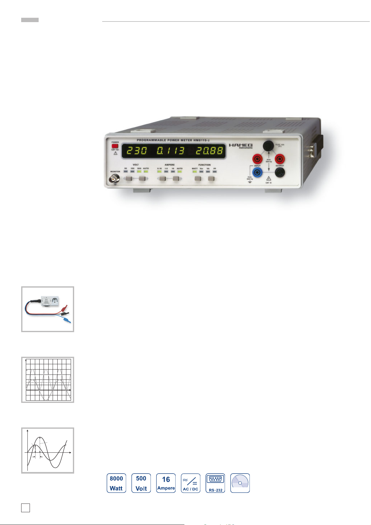
HM8115-2
8 kW Leistungs-Messgerät
HM8115-2
Adapter HZ815
Effektivwert
U
eff
0
Wirkleistung
u
i
û
ϕ
Leistungsmessung bis 8 kW
Simultane Anzeige von Spannung, Strom und Leistung
Messung von Wirk-, Blind- und Scheinleistung
Anzeige des Leistungsfaktors
Automatische Messbereichswahl und einfachste Bedienung
2
u (t)
t
u(t)
Für Messungen an Frequenzwandlern geeignet
Frequenzbereich DC bis 1 kHz
Messdatenerfassung und Bedienung über RS-232 Schnittstelle
î
ωt
4
Änderungen vorbehalten
inklusive
Page 5

8 kW Leistungsmessgerät HM8115-2
TECHNISCHE DATEN
Referenztemperatur: 23 °C ±2 °C
Technische Daten
SPANNUNG – ECHTEFFEKTIVWERT (AC+DC)
Messbereiche: 50 V 150 V 500 V
Auflösung: 0,1 V 1 V 1 V
Genauigkeit: ±(0,4% + 5 Digits) bei 20 Hz – 1 kHz
Eingangsimpedanz: 1 MOhm II 100 pF
Crestfaktor: max. 3,5 am Messbereichende
Eingangsschutz: 500 V
STROM – ECHTEFFEKTIVWERT (AC+DC)
Messbereiche: 160 mA 1,6 A 16 A
Auflösung: 1 mA, 1mA 10 mA
Genauigkeit: ±(0,4% + 5 Digits) bei 20 Hz -1 kHz
Crestfaktor: max. 4 am Messbereichende
Eingangsschutz Input: Sicherung 16 A Superflink (FF),
WIRKLEISTUNG
Messbereiche: 8 W 24 W 80 W 240 W
Auflösung: 1mW 10mW 10mW 100mW
Messbereiche: 800 W 2400 W 8000 W
Auflösung: 100mW 1W 1W
Genauigkeit: ±(0,5% + 10 Digits) bei 20 Hz - 1 kHz
Anzeige: 4stellig, 7-Segment LED
BLINDLEISTUNG
Messbereiche: 8 var 24 var 80 var
Auflösung: 1 mvar 10 mvar 10 mvar
Messbereiche: 240/800 var 2400/ 8000 var
Auflösung: 100 mvar 1 var
Genauigkeit: ±(2,5 % + 10 Digits + 0,02 x P)
Anzeige: 4stellig, 7-Segment LED
±(0,6% + 5 Digits) bei DC
p
±(0,6% + 5 Digits) bei DC
6,3 x 32 mm
±(0,5% + 10 Digits) bei DC
bei 20 Hz – 400 Hz; P = Wirkleistung
BEDIENUNG / ANZEIGEN
Messfunktionen: Spannung, Strom, Leistung, Leistungs-
faktor
Messbereichswahl: automatisch / manuell
Überlaufanzeige: optisch, akustisch
Spannungsanzeige: 3stellig, 7-Segment LED
Stromanzeige: 4stellig, 7-Segment LED
KOMBINIERTE ANZEIGE:
für Wirk-, Blindund Scheinleistung: 4stellig, 7-Segment LED
Leistungsfaktor: 3stellig, 7-Segment LED
VERSCHIEDENES
Netzanschluss: 115/230 V ± 10%, 50/60 Hz
Schutzklasse I, EN 61010 (IEC 1010)
Leistungsaufnahme: ca. 15 W bei 50 Hz
Arbeitstemperaturbereich: 0°....+40 °C
Zulässige rel. Feuchte: < 80%
Gehäusemaße (BxHxT): 285 x 75 x 365 mm
Gewicht: ca. 4 kg
SCHEINLEISTUNG
Messbereiche: 8VA 24VA 80VA
Auflösung: 1 mVA 10 mVA 10 mVA
Messbereiche: 240/800 VA 2400/ 8000 VA
Auflösung: 100 mVA 1 VA
Genauigkeit: ±(0,8% + 5 Digits) bei 20 Hz – 1 kHz
Anzeige: 4stellig, 7-Segment LED
LEISTUNGSFAKTOR
Anzeige: 0,00 bis +1,00
Genauigkeit: ±(2% + 3 digits)
50-60 Hz: U und I (Sinus) und > 1/10 v. Messbereich
MONITORAUSGANG (analog)
Anschluss: BNC- Buchse (galvanische Trennung
v. Messkreis und RS-232 Schnittstelle)
Bezugspotential: Schutzleiteranschluss
Pegel: 1Vav bei Bereichende (2400/8000 Digits)
Genauigkeit: typ. 5 %
Ausgangsimpedanz: ca. 10 kOhm
Bandbreite: DC bis 1 kHz
Fremdspannungsschutz: ± 30 V
SERIELLE SCHNITTSTELLE
Anschluss: D-Sub- Buchse (galvanische Trennung
v. Messkreis und Monitorausgang)
Typ: RS-232 (3 Leitungen)
Protokoll: Xon / Xoff
Übertragungsraten: 1200 / 9600 Baud
Funktionen: Steuerung / Datenabfrage
Lieferumfang: Power Meter HM8115-2, Netzkabel,
Bedienungsanleitung, Software-CD
Als weiteres Zubehör empfehlen wir:
HZ33, HZ34: Messkabel BNC / BNC
HZ42: 19" Einbausatz 2HE für Gehäusehöhe 75 mm
HZ815: Steckdosen-Adapter (Schuko)
Änderungen vorbehalten
5
Page 6
STOP
STOP
STOP
Wichtige Hinweise
Wichtige Hinweise
entwicklung kann bei gleichzeitigem Betrieb aller Geräte, zu
groß werden.
Transport
Symbole
TiPP
(1) (2) (3) (4) (5) (6)
Symbol 1: Achtung - Bedienungsanleitung beachten
Symbol 2: Vorsicht Hochspannung
Symbol 3: Masseanschluss
Symbol 4: Hinweis – unbedingt beachten
Symbol 5: Tipp! – Interessante Info zur Anwendung
Symbol 6: Stop! – Gefahr für das Gerät
STOP
Auspacken
Prüfen Sie beim Auspacken den Packungsinhalt auf Vollständigkeit. Ist der Netzspannungsumschalter entsprechend der
vorhandenen Netzversorgung eingestellt?
Nach dem Auspacken sollte das Gerät auf mechanische Beschädigungen und lose Teile im Innern überprüft werden. Falls
ein Transportschaden vorliegt, ist sofort der Lieferant zu informieren. Das Gerät darf dann nicht in Betrieb genommen
werden.
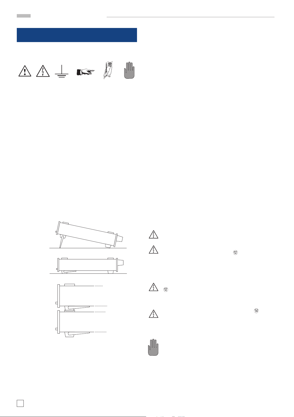
Aufstellen des Gerätes
Das Gerät kann in zwei verschiedenen Positionen aufgestellt
werden: Die vorderen Gerätefüße werden wie in Abbildung 1
aufgeklappt. Die Gerätefront zeigt dann leicht nach oben. (Neigung etwa 10°).
Bewahren Sie bitte den Originalkarton für einen eventuell späteren Transport auf. Transportschäden aufgrund einer mangelhaften Verpackung sind von der Garantie ausgeschlossen.
Lagerung
Die Lagerung des Gerätes muss in trockenen, geschlossenen
Räumen erfolgen. Wurde das Gerät bei extremen Temperaturen transportiert, sollte vor dem Einschalten eine Zeit von
mindestens 2 Stunden für die Akklimatisierung des Gerätes
eingehalten werden.
Sicherheitshinweise
Diese Gerät ist gemäß VDE0411 Teil1, Sicherheitsbestimmungen
für elektrische Mess-, Steuer-, Regel, und Laborgeräte, gebaut
und geprüft und hat das Werk in sicherheitstechnisch einwandfreiem Zustand verlassen. Es entspricht damit auch den Bestimmungen der europäischen Norm EN 61010-1 bzw. der
internationalen Norm IEC 1010-1. Um diesen Zustand zu erhalten und einen gefahrlosen Betrieb sicherzustellen, muss
der Anwender die Hinweise und Warnvermerke, in dieser
Bedienungsanleitung, beachten. Das Gerät entspricht der
Schutzklasse 1, somit sind alle Gehäuse- und Chassisteile mit
dem Netzschutzleiter verbunden. Das Gerät darf aus Sicherheitsgründen nur an vorschriftsmäßigen Schutzkontaktsteckdosen oder an Schutz-Trenntransformatoren der Schutzklasse 2 betrieben werden.
Sind Zweifel an der Funktion oder Sicherheit der Netzsteckdosen aufgetreten, so sind die Steckdosen nach DIN
VDE0100,Teil 610, zu prüfen.
Bild 1
Bild 2
Bild 3
Bleiben die vorderen Gerätefüße eingeklappt, wie in Abbildung
2, lässt sich das Gerät mit vielen weiteren Geräten von HAMEG
sicher stapeln. Werden mehrere Geräte aufeinander gestellt
sitzen die eingeklappten Gerätefüße in den Arretierungen des
darunter liegenden Gerätes und sind gegen unbeabsichtigtes
Verrutschen gesichert. (Abbildung 3).
Es sollte darauf geachtet werden, dass nicht mehr als drei bis
vier Geräte übereinander gestapelt werden. Ein zu hoher
Geräteturm kann instabil werden und auch die Wärme-
Das Auftrennen der Schutzkontaktverbindung innerhalb oder außerhalb des Gerätes ist unzulässig!
Beim Anlegen von berührungsgefährlichen Spannungen an die Eingangsbuchsen INPUT
diesbezüglichen Sicherheitsvorschriften beachtet
werden! Gleichspannung ist erdfrei zu machen!
Wechselspannung ist mit einem Schutztrenntrafo
erdfrei zu machen!
Vor dem Abziehen der Sicherheitsstecker am INPUT
ist sicherzustellen dass diese spannungsfrei sind.
Ansonsten besteht Unfallgefahr, im schlimmsten Fall
Lebensgefahr!
Werden Geräte der Schutzklasse I an OUTPUT
angeschlossen, ist der Schutzleiter PE am Prüfling
separat anzuschließen. Wird dies nicht beachtet,
besteht Lebensgefahr!
Das Gerät darf nur von Fachpersonal geöffnet werden.
Zuvor ist es spannungsfrei zu schalten!
Die Sicherheitsstecker können durch hohe Ströme
STOP
heiß werden!
– Der Netzspannungsumschalter muss entsprechend der
vorhandenen Netzversorgung eingestellt sein.
– Das Öffnen des Gerätes darf nur von einer entsprechend
ausgebildeten Fachkraft erfolgen.
– Vor dem Öffnen muss das Gerät ausgeschaltet und von
allen Stromkreisen getrennt sein.
müssen alle
6
Änderungen vorbehalten
Page 7

STOP
Wichtige Hinweise
In folgenden Fällen ist das Gerät außer Betrieb zu setzen und
gegen unabsichtlichen Betrieb zu sichern:
– Sichtbare Beschädigungen am Gerät
– Beschädigungen an der Anschlussleitung
– Beschädigungen am Sicherungshalter
– Lose Teile im Gerät
– Das Gerät arbeitet nicht mehr
– Nach längerer Lagerung unter ungünstigen Verhältnissen
(z.B. im Freien oder in feuchten Räumen)
– Schwere Transportbeanspruchung
Garantie und Reparatur
HAMEG Geräte unterliegen einer strengen Qualitätskontrolle.
Jedes Gerät durchläuft vor dem Verlassen der Produktion einen 10-stündigen „Burn in-Test“. Im intermittierenden Betrieb wird dabei fast jeder Frühausfall erkannt. Anschließend
erfolgt ein umfangreicher Funktions- und Qualitätstest bei
dem alle Betriebsarten und die Einhaltung der technischen
Daten geprüft werden.
Bei Beanstandungen innerhalb der 2-jährigen Gewährleistungsfrist wenden Sie sich bitte an den Händler, bei dem
Sie Ihr HAMEG Produkt erworben haben. Um den Ablauf zu
beschleunigen, können Kunden innerhalb der Bundesrepublik
Deutschland die Garantiereparatur auch direkt mit HAMEG
abwickeln.
Für die Abwicklung von Reparaturen innerhalb der Gewährleistungsfrist gelten unsere Garantiebedingungen, die im Internet unter http://www.hameg.de eingesehen werden können.
Auch nach Ablauf der Gewährleistungsfrist steht Ihnen der
HAMEG Kundenservice für Reparaturen und Ersatzteile zur
Verfügung.
von 15 °C bis 30 °C. Werte ohne Toleranzangabe sind Richtwerte eines durchschnittlichen Gerätes.
Wartung
Das Gerät benötigt bei einer ordnungsgemäßen Verwendung
keine besondere Wartung. Sollte das Gerät durch den täglichen
Gebrauch verschmutzt sein, genügt die Reinigung mit einem
feuchten Tuch. Bei hartnäckigem Schmutz verwenden Sie ein
mildes Reinigungsmittel (Wasser und 1% Entspan-nungsmittel).
Bei fettigem Schmutz kann Brennspiritus oder Waschbenzin
(Petroleumäther) benutzt werden. Displays oder Sichtscheiben
dürfen nur mit einem feuchten Tuch gereinigt werden.
Verwenden Sie keinen Alkohol, Lösungs- oder Scheuermittel. Keinesfalls darf die Reinigungsflüssigkeit in
das Gerät gelangen. Die Anwendung anderer Reinigungsmittel kann die Kunststoff- und Lackoberflächen
STOP
angreifen.
Netzspannungsumschaltung
Das Gerät arbeitet mit einer Netzwechselspannung von 115 V
oder 230 V 50/60 Hz. Die vorhandene Netzversorgungsspannung
wird mit dem Netzspannungsumschalter
Netzspannungsumschaltung ist
ein Wechsel der Netzeingangssicherungen notwendig. Die
Nennströme der benötigten Sicherungen sind an der Gehäuserückwand abzulesen.
eingestellt. Mit der
Sicherungswechsel der Gerätesicherung
Return Material Authorization (RMA):
Bevor Sie ein Gerät an uns zurücksenden, fordern Sie bitte
in jedem Fall per Internet:
http://www.hameg.de oder Fax eine RMA-Nummer an.
Sollte Ihnen keine geeignete Verpackung zur Verfügung stehen, so können Sie einen leeren Originalkarton über den
HAMEG-Vertrieb (Tel: +49 (0) 6182 800 300, E-Mail:
vertrieb@hameg.de) bestellen.
Bestimmungsgemäßer Betrieb
Die Geräte sind zum Gebrauch in sauberen, trockenen
Räumen bestimmt. Sie dürfen nicht bei besonders großem Staubbzw. Feuchtigkeitsgehalt der Luft, bei Explosionsgefahr sowie
bei aggressiver chemischer Einwirkung betrieben werden.
Die zulässige Umgebungstemperatur während des Betriebes
reicht von +10 °C...+40 °C. Während der Lagerung oder des
Transportes darf die Temperatur zwischen –10 °C und +70 °C
betragen. Hat sich während des Transportes oder der Lagerung Kondenswasser gebildet, muss das Gerät ca. 2 Stunden
akklimatisiert werden, bevor es in Betrieb genommen wird.
Das Gerät darf aus Sicherheitsgründen nur an vorschriftsmäßigen Schutzkontaktsteckdosen oder an Schutz-Trenntransformatoren der Schutzklasse 2 betrieben werden. Die
Betriebslage ist beliebig. Eine ausreichende Luftzirkulation
(Konvektionskühlung) ist jedoch zu gewährleisten. Bei Dauerbetrieb ist folglich eine horizontale oder schräge Betriebslage (vordere Gerätefüße aufgeklappt) zu bevorzugen.
Die Lüftungslöcher und die Kühlkörper des Gerätes
dürfen nicht abgedeckt werden !
Nenndaten mit Toleranzangaben gelten nach einer Anwärmzeit von min. 20 Minuten, im Umgebungstemperaturbereich
Die Netzeingangssicherungen sind von außen zugänglich. Kaltgeräteeinbaustecker und Sicherungshalter bilden eine Einheit.
Das Auswechseln der Sicherung darf nur erfolgen wenn zuvor
das Gerät vom Netz getrennt und das Netzkabel abgezogen wurde. Sicherungshalter und Netzkabel müssen unbeschädigt sein.
Mit einem geeigneten Schraubenzieher (Klingenbreite ca. 2mm)
werden die an der linken und rechten Seite des Sicherungshalters
befindlichen Kunststoffarretierungen nach innen gedrückt. Der
Ansatzpunkt ist am Gehäuse mit zwei schrägen Führungen markiert. Beim Entriegeln wird der Sicherungshalter durch Druckfedern nach außen gedrückt und kann entnommen werden. Die
Sicherungen sind dann zugänglich und können ggf. ersetzt werden. Es ist darauf zu achten, dass die zur Seite herausstehenden
Kontaktfedern nicht verbogen werden. Das Einsetzen des
Sicherungshalters ist nur möglich, wenn der Führungssteg zur
Buchse zeigt. Der Sicherungshalter wird gegen den Federdruck
eingeschoben, bis beide Kunststoffarretierungen einrasten.
Ein Reparieren der defekten Sicherung oder das Verwenden
anderer Hilfsmittel zum Überbrücken der Sicherung ist gefährlich und unzulässig. Dadurch entstandene Schäden am
Gerät fallen nicht unter die Garantieleistungen.
Sicherungstype:
Kaltgerätesteckdose
einfügen.
Größe 5 x 20 mm; 250V~, C;
IEC 127, Bl. III; DIN 41 662
(evtl. DIN 41 571, Bl. 3).
Netzspannung Sicherungs-Nennstrom
230 V 100 mA träge (T)
115 V 200 mA träge (T)
Änderungen vorbehalten
7
Page 8
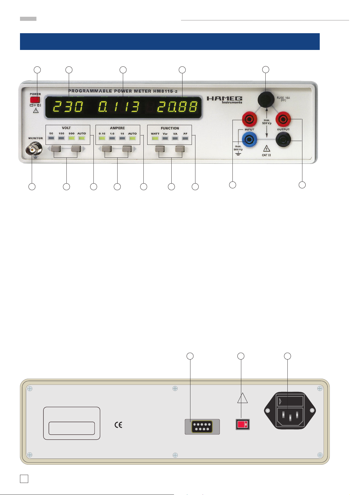
Bezeichnung der Bedienelemente
Bezeichnung der Bedienelemente
1 2
5
Gerätefrontseite
3 4
6
7
8
9
10
11
12 14
13
1. POWER – Netzschalter
2. VOLT Display – Spannungsanzeige
3. AMPERE Display – Stromanzeige
4. FUNCTION Display – Anzeige für Leistung u. PF (power
factor)
5. MONITOR – Monitorausgang
6. VOLT Tasten – Bereichsumschalter für Spannung
7. VOLT LED – Anzeige Spannungsbereich
8. AMPERE Tasten – Bereichsumschalter für Strom
9. AMPERE LED – Anzeige Strombereich
10. FUNCTION Tasten – Bereichsumschalter Messfunktion
HAMEG INSTRUMENTS
Programmable Power Meter
HM8115-2
Made in Germany
11. FUNCTION LED – Anzeige Messfunktion
12. INPUT – Eingang Stromversorgung für Prüfling
13. FUSE – Sicherung für den Messkreis
14. OUTPUT – Ausgang zum Prüfling
Geräterückseite
15. Serielle Schnittstelle RS-233 (9 pol. D-Sub Buchse)
16. Netzspannungsumschalter
17. Kaltgeräteeinbaustecker mit Netzsicherung
16 1715
!
CAT II
RS-232
Serial port
Voltage
230V
Selector
INTERNAL INSTRUMENT SUPPLY
115 - 230 VAC / 50 - 60 Hz
Power Fuse: IEC 127 – III, 5 x 20 mm
Träge, temporisé, time lag, lento
230 V: T100 mA / 115 V: T200 mA
Watts (max.): 15 at 230 V / 50 Hz
8
Änderungen vorbehalten
Page 9
STOP
Messgrundlagen
Messgrundlagen
Verwendete Abkürzungen und Zeichen
W Wirkleistung P
VA Scheinleistung S
var Blindleistung Q
u(t) Spannung Momentanwert
u²(t) Spannung quadratischer Mittelwert
IÛI Spannung Gleichrichtwert
Spannung Effektivwert
U
eff
û Spannung Spitzenwert
Strom Effektivwert
I
eff
î Strom Spitzenwert
ϕ Phasenverschiebung (Phi) zwischen U und I
cos ϕ Leistungsfaktor bei sinusförmigen Größen
PF Leistungsfaktor (power factor) bei nichtsinusförmigen
Größen
Arithmetischer Mittelwert
T
1
= ––
∫|x
x
(t)
Der arithmetische Mittelwert eines periodischen Signals ist
der gemittelte Wert aller Funktionswerte, die innerhalb einer
Periode T vorkommen. Der Mittelwert eines Signals entspricht
dem Gleichanteil.
– Ist der Mittelwert = 0 , liegt ein reines Wechselsignal vor.
– Für Gleichgrößen ist der Mittelwert = Augenblickswert.
– Für Mischsignale entspricht der Mittelwert dem Gleich-
anteil
|· dt
(t)
T
0
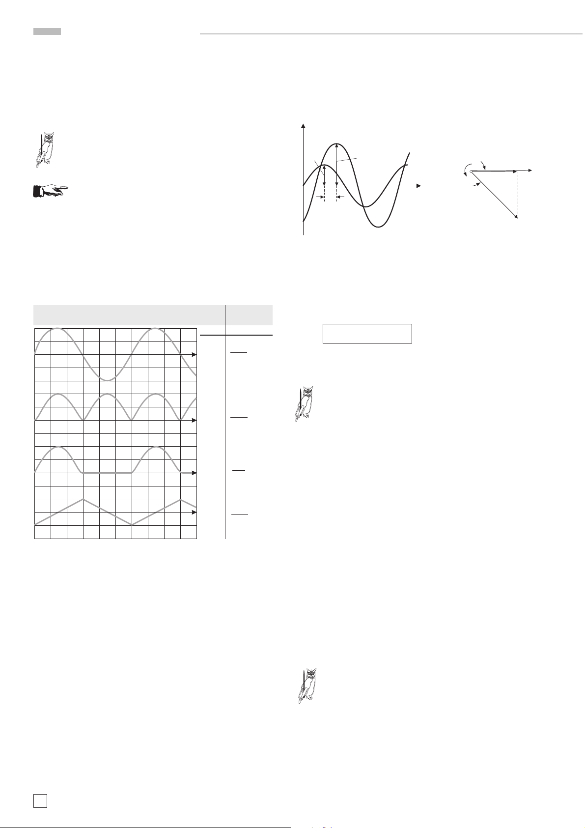
Bei einer sinusförmigen Wechselspannung u(t) = û sin
ωt ist
der Gleichrichtwert das 2/π-fache (0,637fache) des Scheitelwertes. Hier Formel sinusförmiger Gleichrichtwert
T
IuI =
12
––
∫|û sin ωt| dt = –– û = 0,637û
0
T
π
Effektivwert
Der quadratische Mittelwert x²(t) eines Signals entspricht dem
Mittelwert des quadrierten Signals.
T
1
2
= ––
x
(t)
Wird aus dem quadratischen Mittelwert die Wurzel gezogen,
ergibt sich der Effektivwert des Signals X
= ––
x
eff
Bei Wechselspannungssignalen möchte man wie bei Gleichspannungssignalen die selben Formeln zur Berechnung von
Widerstand, Leistung, etc verwenden. Wegen der wechselnden Momentangrößen wird der Effektivwert (engl. „RMS“ –
Root Mean Square) definiert. Der Effektivwert eines Wechselsignals erzeugt den selben Effekt wie ein entsprechend großes Gleichsignal.
Beispiel:
Eine Glühlampe, versorgt mit einer Wechselspannung von
, nimmt die gleiche Leistung auf und leuchtet genauso
230 V
eff
hell, wie eine Glühlampe versorgt mit einer Gleichspannung
von 230 V
DC
Bei einer sinusförmigen Wechselspannung u(t) = û sin ωt ist der
Effektivwert das 1/√2-fache (0,707-fache) des Scheitelwertes.
––
U =
2
∫x
dt
(t)
T
0
eff
T
1
2
∫x
dt
(t)
T
0
.
T
1û
(û sinωt)2 dt = –– = 0,707û
∫
T
0
2
Gleichrichtwert
T
1
|x| = ––
Der Gleichrichtwert ist das arithmetische Mittel der Beträge
der Augenblickswerte. Die Beträge der Augenblickswerte ergeben sich durch Gleichrichtung des Signals. Der Gleichrichtwert wird berechnet durch das Integral über eine Periode von Beträgen der Spannungs- oder Stromwerte.
û
0
IuI
0
T
∫|x
0
(t)
||dt
u (t)
U
eff
0
u(t)
Formfaktor
Wird der vom Messgerät ermittelte Gleichrichtwert mit dem
Formfaktor des Messsignals multipliziert ergibt sich der Effektivwert des Signals. Der Formfaktor eines Signals ermittelt sich nach folgender Formel:
U
––––
F =
t
IuI Gleichrichtwert
Bei reinen sinusförmigen Wechselgrößen beträgt der
Formfaktor:
t
TiPP
F =
–––– = 1,11
2√2
Effektivwert
eff
= –––––––––––––––
π
2
t
Änderungen vorbehalten
9
Page 10
STOP
STOP
STOP
Messgrundlagen
Crestfaktor
Der Crestfaktor (auch Scheitelfaktor genannt) beschreibt um
welchen Faktor die Amplitude (Spitzenwert) eines Signals größer ist als der Effektivwert. Er ist wichtig bei der Messung von
impulsförmigen Größen.
û Spitzenwert
––––
C =
Bei reinen sinusförmigen Wechselgrößen beträgt das
Verhältnis: √2 = 1,414
TiPP
Messwerte ungenau, da das Messgerät übersteuert wird.
Die Genauigkeit des berechneten Effektivwertes ist abhängig
vom Crestfaktor und verschlechtert sich mit höherem
Crestfaktor des Messsignals. Die Angabe des maximal zulässigen Crestfaktors (techn. Daten) bezieht sich auf das Messbereichende. Wird nur ein Teil des Messbereiches genutzt (z.B.
230 V im 500 V-Bereich), darf der Crestfaktor größer sein.
Formfaktoren
= –––––––––––––––
U
eff
Effektivwert
Wird bei einem Messgerät der maximal zulässige
Crestfaktor überschritten sind die ermittelten
Crest-Crest-
Crest-
Crest-Crestfaktorfaktor
faktor
faktorfaktor
CC
C
CC
Form-Form-
Form-
Form-Formfaktorfaktor
faktor
faktorfaktor
FF
F
FF
ππ
π
ππ
2 = 1,11
2
2
für Lasten mit induktiven bzw. kapazitiven Anteilen. Betrifft
es die Quelle und die Last, erfolgt eine gegenseitige Beeinflussung. Die Wirkleistung errechnet sich aus der effektiven
Spannung und dem Wirkstrom. Im Zeigerdiagramm ist der
Wirkstrom die Stromkomponente mit der selben Richtung wie
die Spannung.
u
i
û
î
ω
ϕ
I cos ϕ
ϕ
ωt
U
I
Wenn: P = Wirkleistung
= Spannung Effektivwert
U
eff
= Strom Effektivwert
I
eff
ϕ = Phasenverschiebung zwischen U und I
ergibt sich für die Wirkleistung
· I
P = U
· cosϕ
eff
eff
Der Ausdruck cosϕ wird als Leistungsfaktor bezeichnet.
2 = 1,57
Leistung
Die Leistung von Gleichgrößen (Gleichstrom, Gleichspannung)
ist das Produkt von Strom und Spannung.
Bei der Wechselstromleistung muss zusätzlich zu Strom und
Spannung auch die Kurvenform und die Phasenlage berücksichtigt werden. Bei sinusförmigen Wechselgrößen (Strom,
Spannung) und bekannter Phasenverschiebung, lässt sich die
Leistung leicht berechnen. Schwieriger wird es, wenn es sich
um nichtsinusförmige Wechselgrößen handelt.
Mit dem Power Meter lässt sich der Mittelwert der augenblicklichen Leistung unabhängig von der Kurvenform messen.
Voraussetzung hierfür ist, dass die bezüglich Crestfaktor und
Frequenz spezifizierten Grenzen nicht überschritten werden.
Wirkleistung (Einheit Watt, Kurzzeichen P)
Induktivitäten oder Kapazitäten der Quelle führen zu Phasenverschiebungen zwischen Strom und Spannung; das gilt auch
ππ
π
ππ
2 = 1,11
2
2
ππ
π
ππ
2
3 = 1,15
22
2
22
3
Die Momentanleistung ist die Leistung zum Zeitpunkt
(t) und errechnet sich aus dem Produkt des Stromes
und der Spannung zum Zeitpunkt (t).
TiPP
p
=i
(t)
· u
(t)
(t)
bei Sinus gilt:
p
= û sin (ωt + ϕ) · î sin ωt
(t)
Die effektive Leistung, die sogenannte Wirkleistung, ist der
zeitliche arithmetische Mittelwert der Momentanleistung. Wird
über eine Periodendauer integriert und durch die Periodendauer dividiert ergibt sich die Formel für die Wirkleistung.
T
1
––
∫î sin ωt · û sin (ωt + ϕ) dt
P =
T
0
î · û · cos ϕ
P = ––––––––––––––
P = U
Das Maximum des Leistungsfaktors cos
sich bei einer Phasenverschiebung von
2
· I
· cos ϕ
eff
eff
ϕ = 1 ergibt
ϕ = 0°. Die
wird nur in einem Wechselstromkreis ohne Blindwiderstand erreicht.
In einem Wechselstromkreis mit einem idealen
Blindwiderstand beträgt die Phasenverschiebung
ϕ = 90°. Der Leistungsfaktor cos ϕ = 0. Der Wechsel-
TiPP
strom bewirkt dann keine Wirkleistung.
Blindleistung (Einheit var, Kurzzeichen Q)
Die Blindleistung errechnet sich aus der effektiven Spannung
und dem Blindstrom. Im Zeigerdiagramm ist der Blindstrom
die Stromkomponente senkrecht zur Spannung. (var = Volt Ampere réactif)
10
Änderungen vorbehalten
Page 11
STOP
STOP
Messgrundlagen
Wenn: Q = Blindleistung
= Spannung Effektivwert
U
eff
I
= Strom Effektivwert
eff
ϕ = Phasenverschiebung
zwischen U und I
ergibt sich für die Blindleistung
· I
Q=U
Blindströme belasten das Stromversorgungsnetz. Um
die Blindleistung zu senken muss der Phasenwinkel ϕ
verkleinert werden. Da Transformatoren, Motoren,
etc. das Stromversorgungsnetz induktiv belasten
werden zusätzliche kapazitive Widerstände (Kondensatoren) zugeschaltet. Diese kompensieren den induktiven Blindstrom.
TiPP
Beispiel für Leistung mit Blindanteil
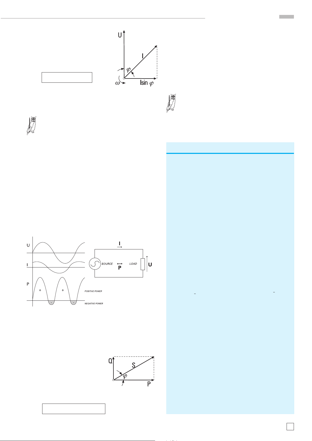
Bei Gleichgrößen sind Augenblickswerte von Strom und Spannung zeitlich konstant. Folglich ist auch die Leistung konstant.
Im Gegensatz dazu folgt der Augenblickswert von Misch- und
Wechselgrößen zeitlichen Änderungen nach Betrag (Höhe) und
Vorzeichen (Polarität). Ohne Phasenverschiebung liegt immer
die gleiche Polarität von Strom und Spannung vor. Das Produkt von Strom x Spannung ist immer positiv und die Leistung wird an der Last vollständig in Energie umgewandelt. Ist
im Wechselstromkreis ein Blindanteil vorhanden ergibt sich
eine Phasenverschiebung von Strom und Spannung. Während
der Augenblickswerte in denen das Produkt von Strom und
Spannung negativ ist, nimmt die Last (induktiv oder kapazitiv)
keine Leistung auf. Dennoch belastet diese sogenannte Blindleistung das Netz.
· sinϕ
eff
eff
Leistungsfaktor
Der Leistungsfaktor PF (power factor) errechnet sich nach der
Formel:
PF =
PF = Leistungsfaktor
S = Scheinleistung
P = Wirkleistung
û = Spannung Spitzenwert
î = Strom Spitzenwert
Nur für sinusförmige Ströme und Spannungen
gilt: PF = cos ϕ
TiPP
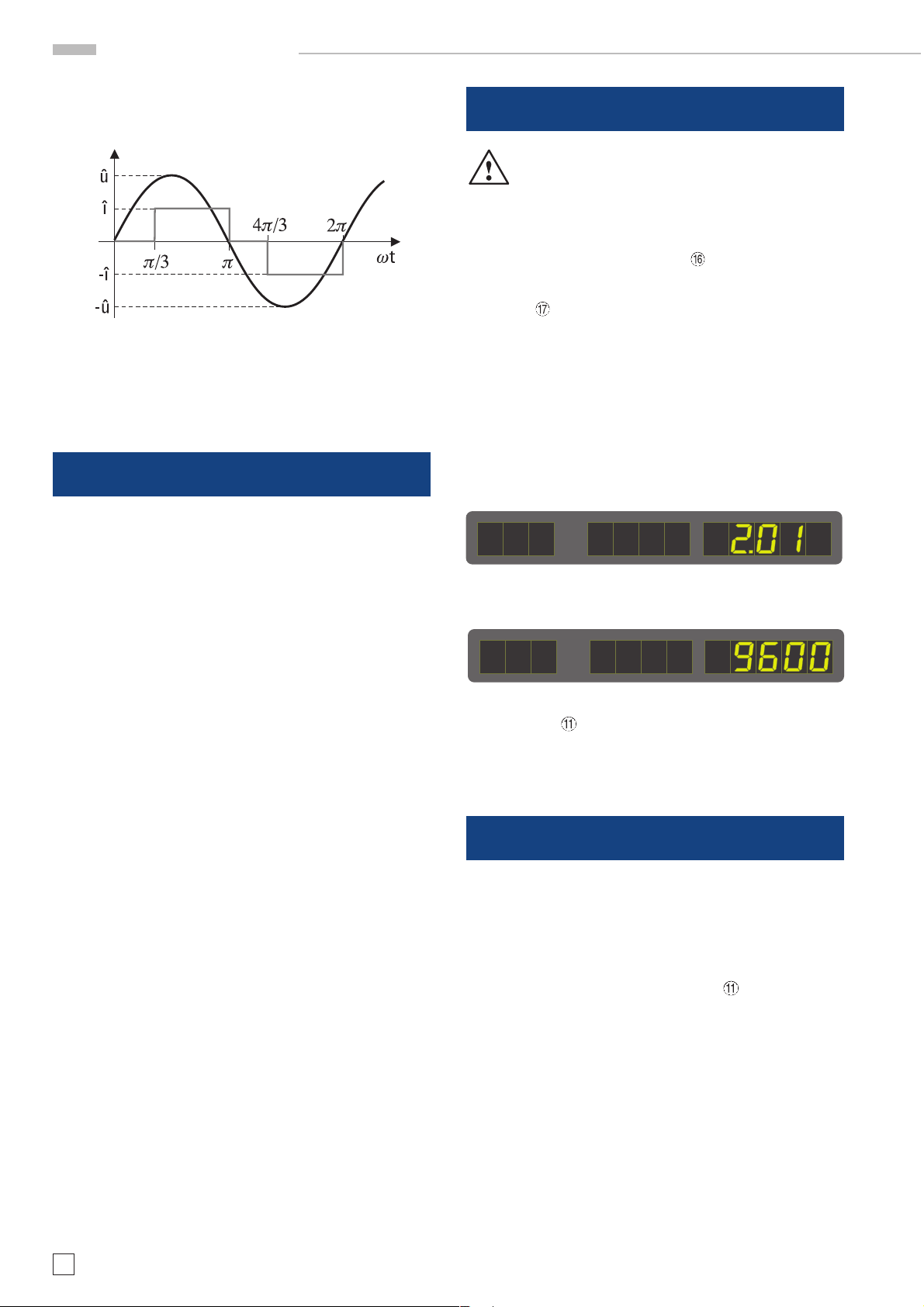
Ist zum Beispiel der Strom rechteckförmig und die Spannung
sinusförmig errechnet sich der Leistungsfaktor aus dem Verhältnis von Wirkleistung zu Scheinleistung. Auch hier lässt
Rechenbeispiel Leistungsfaktor
Der Effektivwert der Spannung beträgt:
U
P
––––
S
û
= —— = 229,8 V ≈ 230 V
eff
√2
Der Effektivwert des Stromes ergibt sich aus:
2π
I
eff
J
eff
J
eff
1
= ––
∫î2 · dϕ
2π
0
2
î
= ––
2π 33
2
= î
· –– = î · ––
π 4π
· [( π – –– ) + (2π –
22
33
–––
)]
Scheinleistung (Einheit Voltampere, Kurzzeichen VA)
Werden die in einem Wechselstromkreis gemessenen Werte
von Spannung und Strom multipliziert ergibt das stets die
Scheinleistung. Die Scheinleistung ist die geometrische Summe von Wirkleistung und Blindleistung.
Wenn: S = Scheinleistung
P = Wirkleistung
Q = Blindleistung
= Spannung Effektivwert
U
eff
= Strom Effektivwert
I
eff
ergibt sich für die Scheinleistung
I
= 12,25 A · –– = 10,00 A
eff
Die Scheinleistung S entspricht:
S = U
Die Wirkleistung errechnet sich aus:
P =
P = ––––
P = –––– · 325 V · 12,25 A = 1900 W
Der Leistungsfaktor PF berechnet sich aus:
PF = ––– = ––––––––––– = 0,826
Strom und Spannung sind in unserem Beispiel nicht
phasenverschoben. Dennoch muss es eine Blindleistung
geben, da die Scheinleistung größer als die Wirkleistung
ist. Da der Strom eine andere Kurvenform als die Spannung besitzt, spricht man davon, dass der Strom gegenüber der Spannung „verzerrt“ ist. Deshalb heißt diese Art
von Blindleistung auch „Verzerrungsblindleistung“.
· I
= 230 V · 10,0 A = 2300 VA
eff
eff
π
1û · î
––
∫ û · î sin ϕ · dϕ = ––––
ππ
π
3
û · î 1,5
– (-1)) – (-0,5)
[(
ππ
1,5
π
P 1900 W
S 2300 VA
2
3
=
]
– cos ϕ
[
–––– · û · î
π
]
π
3
S = P2 + Q
2
= U
eff
x J
Q = S2 – P2 = (2300 VA)2 – (1900 W)2 = 1296 var
eff
Änderungen vorbehalten
11
Page 12
Gerätekonzept
sich eine Blindleistung bestimmen. Aufgrund dessen, dass der
Strom eine andere Kurvenform besitzt als die Spannung, nennt
man diese Blindleistung auch Verzerrungsblindleistung.
Einführung in die Bedienung des HM8115-2
Achtung - Bedienungsanleitung beachten
Beachten Sie bitte besonders bei der ersten Inbetriebnahme
des Gerätes folgende Punkte:
û = 325,00 V
î = 12,25 A
Gerätekonzept des HM8115-2
Das Power-Meter HM8115-2 misst je einmal die Spannung
mit einem Echteffektivwertwandler und den Strom mit einem
Echteffektivwertwandler. Die Momentanleistung wird mit einem Analogmultiplizierer ermittelt. Die Spannung und der
Strom zum Zeitpunkt (t) werden gemessen und multipliziert.
Die Wirkleistung wird dann durch Integration der Momentanleistung über eine Periode T gebildet. Alle weiteren Werte
werden berechnet.
Die Scheinleistung S ergibt sich durch die Multiplikation der
gemessenen Effektivspannung mit dem Effektivstrom.
S = U
· I
eff
eff
– Der Netzspannungsumschalter
Netzspannung eingestellt und die richtigen Sicherungen
befinden sich im Sicherungshalter des Kaltgeräteeinbausteckers
– Vorschriftsmäßiger Anschluss an Schutzkontaktsteckdose
oder Schutz-Trenntransformatoren der Schutzklasse 2
– Keine sichtbaren Beschädigungen am Gerät
– Keine Beschädigungen an der Anschlussleitung
– Keine losen Teile im Gerät
Selbsttest
Einschalten des HM8115-2 mit dem Netzschalter Power
LED-Anzeige für FUNCTION zeigt die Versionsnummer der
Firmware (z.B. „2.01“).
LED-Anzeige für FUNCTION
Übertragungsrate der seriellen Schnittstelle (z.B. „9600“)
Das Gerät schaltet in den Modus Wirkleistung messen. Die
bei FUNCTION
AUTO-Funktion wird eingeschaltet und für die Spannungs- und
Strom-anzeige der beste Messbereich automatisch eingestellt.
.
mit „WATT“ beschriftete LED leuchtet. Die
ist auf die verfügbare
zeigt die eingestellte
Die Blindleistung berechnet sich aus der Quadratwurzel von
Scheinleistung minus Wirkleistung.
P
S
2
Q = S2 – P
Der Leistungsfaktor PF wird aus dem Quotienten von Wirkleistung und Scheinleistung berechnet. Dies hat den Vorteil,
dass der „richtige“ Leistungsfaktor angezeigt wird. Würde über
eine Phasenwinkelmessung der cosϕ bestimmt, ist der angezeigte Wert des Leistungsfaktors bei verzerrten Signalen
falsch. Dies ist der Fall bei Schaltnetzteilen, Phasenanschnittsteuerungen, Gleichrichterschaltungen, etc.
PF =
––––
Die Momentanleistung kann am Monitorausgang mit einem
Oszilloskop betrachtet werden. Das Gerät selbst ist mit der
seriellen Schnittstelle steuerbar. Die gemessenen und errechneten Werte lassen über die Schnittstelle auslesen und in der
dazugehörigen Software bearbeiten. Messkreis, Monitor und
Schnittstelle sind galvanisch getrennt.
Bedienelemente und Anzeigen
POWER
Netzschalter mit Symbolen für Ein (I) und Aus (O).
Mit dem Einschalten des Gerätes zeigt die LED-Anzeige für
FUNCTION
„2.01“), danach die Übertragungsrate der seriellen Schnittstelle (z.B. „9600“). Anschließend schaltet das Gerät in den
Modus Wirkleistung. Die bei FUNCTION
schriftete LED leuchtet. Die AUTO- Funktion wird eingeschaltet und für die Spannungs- und Stromanzeige der beste Messbereich automatisch eingestellt.
VOLT Display
Die Spannungsanzeige zeigt die Spannung am Ausgang des
Messkreises. Die Spannung ist, bedingt durch den Spannungsabfall am Shunt, geringfügig kleiner als die Eingangsspannung.
Ist die Spannung für den Messbereich zu hoch (Overrange),
zeigt die Anzeige drei blinkende horizontale Striche „ – – – „.
Um eine Spannungsanzeige zu erhalten, muss mit der rechten VOLT-Taste
AUTO-Funktion gewählt werden.
kurz die Versionsnummer der Firmware (z.B.
mit „WATT“ be-
ein größerer Spannungsbereich oder die
12
Änderungen vorbehalten
Page 13

Bedienelemente und Anzeigen
1 2
5
AMPERE Display
Die Stromanzeige zeigt den Strom an, der im Messkreis fließt.
Ist der Strom für den Messbereich zu hoch (Overrange), zeigt
die Anzeige vier blinkende horizontale Striche „ - - - - „ . Um
eine Stromanzeige zu erhalten, muss mit der rechten AMPERE-Taste
Funktion gewählt werden.
FUNCTION Display
Das FUNCTION Display zeigt den Messwert der aktuellen
Funktion an.
Wählbar sind: Wirkleistung in Watt
Die Funktionswahl wird mit den FUNCTION Tasten
nommen. Die Einstellung wird mit der zugehörigen LED angezeigt.
Im Falle fehlerhafter Messungen im falschen Messbereich bei
VOLT oder AMPERE zeigt die Funktionsanzeige drei/vier
horizontale Striche „ - - - - „ , unabhängig von der eingestellten Funktion.
6
ein größerer Strombereich oder die AUTO-
Blindleistung in var
Scheinleistung in VA
Leistungsfaktor PF (power factor)
7
3 4
8
9
vorge-
13
10
11
Die neue Einstellung wird permanent gespeichert bis wieder
eine Änderung erfolgt.
VOLT
Drucktasten und Messbereichs LED für die manuelle oder automatische Wahl des Spannungsbereiches.
Nach dem Einschalten des HM8115-2 leuchtet sofort die
AUTO-LED. Das Gerät wählt automatisch entsprechend der
am Messkreis anliegenden Spannung den geeigneten
Spannungsbereich. Dieser wird zusätzlich zur AUTO-LED mit
einer weiteren LED angezeigt. Ändert sich die Spannung am
Messkreis und ein anderer Messbereich ist geeigneter, schaltet die Messbereich-Automatik selbständig um.
Mit dem Betätigen einer der Tasten zum Umschalten des
Messbereichs wird die Messbereich-Automatik abgeschaltet
und die AUTO-LED erlischt. Danach kann der Messbereich manuell mit einer der VOLT-Tasten gewählt werden.
Die Messbereich-Automatik kann mit Betätigen der rechten
VOLT-Taste wieder eingeschaltet werden. Die AUTO-LED leuchtet wieder.
Die VOLT- Anzeige
nung an. Wird manuell ein zu niedriger Messbereich gewählt,
signalisiert das HM8115-2 durch Blinken von 3 waagrechten
Strichen „- - -„ und einem Warnsignal „Overrange“.
12 14
zeigt die am Messkreis anliegende Span-
Bei PF-Messung zeigt das Display 4 horizontale Striche „ - - - - „
wenn kein Phasenwinkel bestimmbar ist. Das kann folgende Ursachen haben:
1. Es fließt kein Strom
2. Im Messkreis fließt nur Gleichstrom.
3. Wechselspannung und/oder Wechselstrom im Messkreis
sind zu klein.
4. Manuell gewählte Messbereiche für VOLT und/oder AMPERE sind zu klein oder zu groß.
Warnsignal bei Messbereichsüberschreitung
Messbereichsüberschreitungen werden vom POWER METER
durch Blinken der jeweiligen Anzeige und einem akustischen
Warnsignal angezeigt.
Warnsignal EIN/AUS
HM8115-2 mit POWER
HM8115-2 einschalten und die rechte Taste der FUNCTION
Tasten
Die rechte FUNCTION Taste erst loslassen, wenn die FUNCTION LED „WATT“ leuchtet.
drücken
ausschalten
AMPERE
Drucktasten und Messbereichs LED für die manuelle oder automatische Wahl des Strombereiches.
Nach dem Einschalten des HM8115-2 leuchtet sofort die
AUTO-LED. Das Gerät wählt automatisch entsprechend des
im Messkreis fließenden Stromes den geeigneten Strombereich. Dieser wird zusätzlich zur AUTO-LED mit einer weiteren LED angezeigt. Ändert sich der Strom im Messkreis und
ein anderer Messbereich ist geeigneter, schaltet die Messbereich-Automatik selbständig um.
Mit dem Betätigen einer der Tasten zum Umschalten des
Messbereichs wird die Messbereich-Automatik abgeschaltet. Die AUTO-LED erlischt. Danach kann der Messbereich mit
einer der AMPERE- Tasten gewählt werden.
Die Messbereich-Automatik kann mit Betätigen der rechten
AMPERE- Taste wieder eingeschaltet werden. Die AUTO-LED
leuchtet wieder.
Die AMPERE- Anzeige
Strom an. Wird manuell ein zu niedriger Messbereich gewählt,
signalisiert das HM8115-2 durch Blinken von 4 waagrechten
Strichen „- - - -„ und einem Warnsignal „Overrange“.
zeigt den im Messkreis fließenden
Änderungen vorbehalten
13
Page 14

STOP
STOP
STOP
STOP
Bedienelemente und Anzeigen
FUNCTION
Drucktasten und Anzeige
LED für die Auswahl der
Messfunktion.
Wählbar sind:
Wirkleistung in Watt
Blindleistung in V
ar
Scheinleistung in VA
Leistungsfaktor PF
(power factor)
WATT (Wirkleistung)
Nach dem Einschalten des
HM8115-2 befindet sich das
Gerät immer im Modus Wirkleistungsmessung. Die
WATT-LED leuchtet und das
FUNCTION Display
Wirkleistung an. Mit Betätigen der
FUNCTION-Tasten
zeigt die
werden die
10
11
anderen Messfunktionen
ausgewählt.
Var (Blindleistung)
Mit dieser Messfunktion wird die Blindleistung gemessen. Es
leuchtet die Var-LED und das FUNCTION Display
zeigt die
Blindleistung an.
Die Blindleistung wird sowohl bei kapazitiven Lasten und als
bei induktiven Lasten als positiver Wert (ohne Vorzeichen) angezeigt.
Strom und die Spannung haben sinusförmigen
Verlauf. Nur dann entspricht der Leistungsfaktor PF
dem cosϕ des Winkels der Phasenverschiebung
zwischen der Spannung an der Last und dem, durch
die Last fließenden, Strom.
TiPP
Geräteanschlüsse
MONITOR (BNC-Buchse)
Der Monitorausgang ermöglicht
die Anzeige der Augenblickswerte der Leistung (Momentanleistung) mit einem Oszilloskop.
1
Die Momentanleistung ist die Leistung zum Zeitpunkt
(t) und errechnet sich aus dem Produkt des Stromes
und der Spannung zum Zeitpunkt (t).
TiPP
= i
· u
p
(t)
(t)
(t)
5
Die Blindleistungsanzeige zeigt auch dann korrekte
Werte an, wenn Strom und Spannung nicht sinusförmig sind. Da die Scheinleistung (U
eff
Wirkleistung (arithmetischer Mittelwert von u
unabhängig von der Kurvenform sind, kann die Blindleistung aus diesen Messwerten errechnet werden.
TiPP
PF (Leistungsfaktor)
Mit dieser Messfunktion wird der Leistungsfaktor PF (power
factor) gemessen. Mit dem Aufruf dieser Funktion leuchtet
die zugeordnete LED und die FUNCTION-Anzeige
Verhältnis von Wirkleistung / Scheinleistung an. Mit dem Power Meter läßt sich der Mittelwert der augenblicklichen Leistung unabhängig von der Kurvenform messen. Voraussetzung
hierfür ist, daß die bezüglich Crestfaktor und Frequenz spezifizierten Grenzen nicht überschritten werden. Der Leistungsfaktor PF ist unabhängig von der Kurvenform der gemessenen Größen, solange der Crestfaktor und die Frequenz die
spezifizierten Grenzen des Power Meter nicht überschreiten.
PF =
P
––––
S
Die FUNCTION-Anzeige
zeigt nur bei Wechsel-
größen einen Wert für PF an. Beide Wechselgrößen
(Strom und Spannung) müssen in ausreichender Höhe vorliegen (s. technische Daten). Bei nicht ausreichender Höhe
und bei Gleichgrößen (Gleichstrom, Gleichspannung) werden
4 waagrechte Striche angezeigt.
Würde statt dem Leistungsfaktor PF die Phasenverschiebung ϕ von Strom und Spannung gemessen, lässt
sich daraus auch der Leistungsfaktor cosϕ bestimmen. Dieser ist aber nur für echte sinusförmige
Verläufe der Messgrößen direkt anwendbar. Sind die
Spannung und/oder Strom im Versorgungsnetz
verzerrt entspricht die Größe cosϕ nicht dem „wirklichen“ Leistungsfaktor. Bei verzerrten Messgrößen ist
TiPP
die Verzerrungsblindleistung zu berücksichtigen.
· I
eff
) und die
· i
(t)
zeigt das
bei Sinus gilt: p
= û sin (ωt + ϕ) · î sin ωt
(t)
Die effektive Leistung, die sogenannte Wirkleistung, ist der
)
(t)
zeitliche arithmetische Mittelwert der Momentanleistung. Wird
über eine Periodendauer integriert und durch die Periodendauer dividiert ergibt sich die Formel für die Wirkleistung.
T
1
P =
––
∫î sin ωt · û sin (ωt + ϕ) dt
T
0
î · û · cos ϕ
P = ––––––––––––––
P = U
2
· I
· cos ϕ
eff
eff
Positive Leistung wird als positives Strom-Spannungs-Produkt auf dem Oszilloskop angezeigt, negative Leistung als
negatives Strom-Spannungs-Produkt. Unabhängig davon ob
die Funktion WATT, Var, VA oder PF am Gerät ausgewählt
wurde zeigt der Monitorausgang die Momentanleistung an.
Werden Gleichspannung und Gleichstrom gemessen zeigt der
Monitorausgang ein Gleichspannungssignal.
Der Schirmanschluss der BNC-Buchse ist galvanisch mit dem
Chassis verbunden. Das Ausgangssignal an der Buchse ist
durch einen Transformator galvanisch vom Messkreis und der
RS-232 Schnittstelle getrennt.
Es erfolgt eine automatische Korrektur der temperaturabhängigen Drift. Die Häufigkeit der Korrektur hängt von der
Temperatur ab. Während der Korrektur (ca. 100 ms) liegt kein
Signal am Monitorausgang an und die Ausgangsspannung
beträgt 0 Volt. Die automatische Korrektur erfolgt zu Beginn
ca. alle 3 Sekunden innerhalb der ersten Minute. Danach erfolgt die Korrektur in einem Abstand von etwa 2 Minuten.
14
Änderungen vorbehalten
Page 15

STOP
Bedienelemente und Anzeigen
Die Ausgangsspannung an der MONITOR-Buchse
beträgt im arithmetischen Mittel 1 V
am Bereich-
av
ende der WATT- Anzeige. Der Bereich der
Leistungsanzeige wird nicht angezeigt, kann aber leicht
errechnet werden. Er ist das Produkt des Spannungs-(VOLT)
und des Strom- (AMPERE) Bereiches.
Leistungsbereich berechnen:
50 V x 0,16 A = 2408W 1 V (Mittelwert)
150 V x 16,0 A = 2400 W 1 V (Mittelwert)
500 V x 1,6 A = 800 W 1 V (Mittelwert)
Bei maximal sinusförmiger Spannung und Strom im
Messbereich zeigt der Monitorausgang ein sinusförmiges Signal mit 2 V
. Bei reinem Wirkanteil ist die
pp
Nulllinie bei 0 V und das Monitorsignal schwingt zwischen 0 V und 2 V. Im arithmetischen Mittel entsprechend 1 V
(avarage).
av
Bei maximaler Gleichspannung und Gleichstrom im
Messbereich zeigt der Monitorausgang ein Gleichsignal mit 1 V.
TiPP
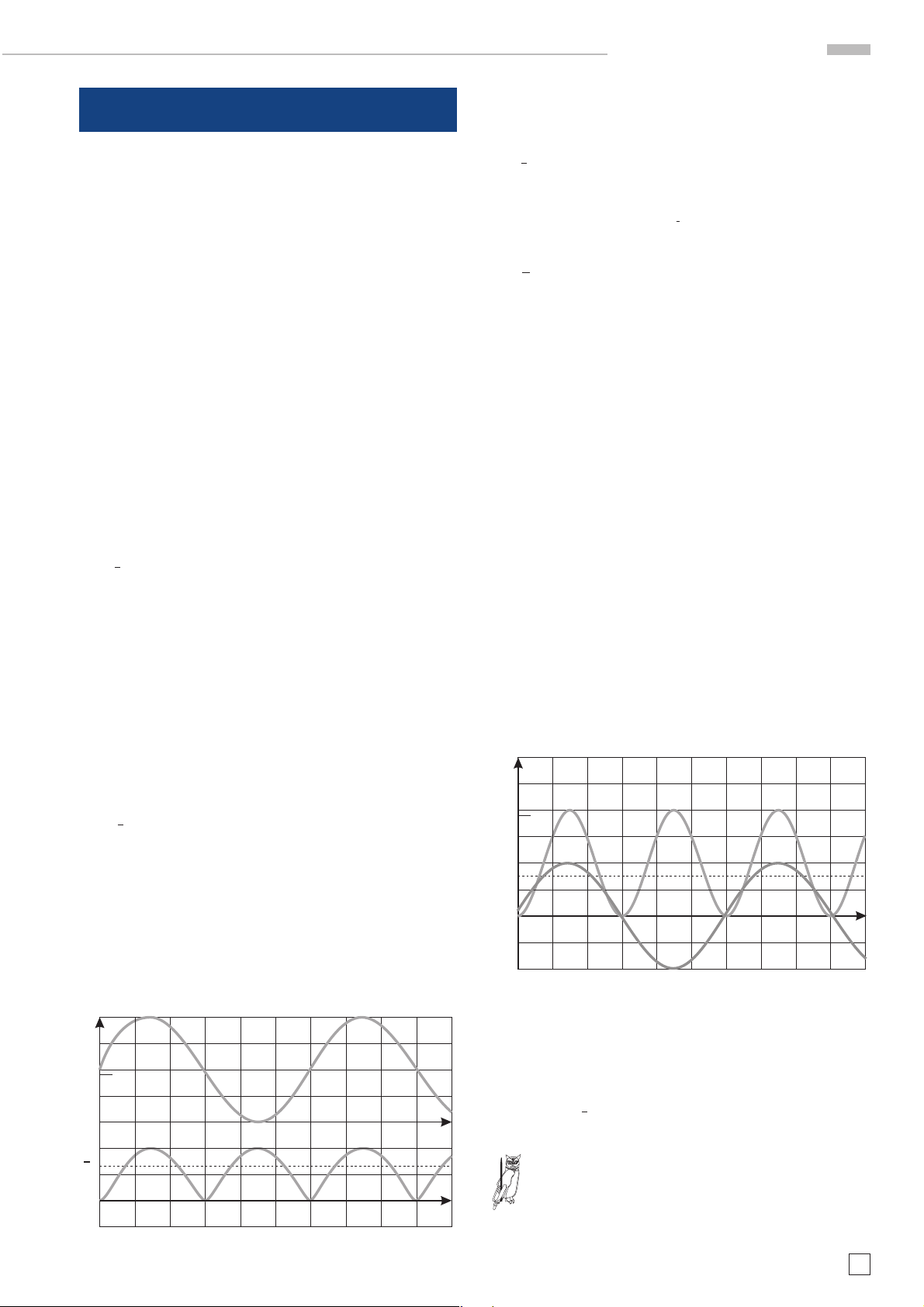
Beispiel 1:
Ein Draht-Widerstand mit 1,47 kΩ wird als Last an eine Spannung von 70 V
/ 50 Hz angeschlossen. Die Abbildung zeigt den
eff
Spannungsverlauf an der R-Last und das Signal am Monitorausgang.
Die Messung mit dem HM8115-2 erfolgt im 150 VOLT- und
0,16 AMPERE-Bereich. Das Produkt der beiden Bereiche beträgt 24 W. Entsprechend der Spezifikation beträgt die Spannung am MONITOR-Ausgang 1 V
, wenn dem Messkreis eine
ar
Leistung von 24 Watt entnommen wird.
Die mittlere Leistung beträgt somit ca. 3,24 Watt. (Ablesegenauigkeit Oszilloskop!)
Das HM8115-2 zeigt folgende Messwerte:
= 70 V Q = 0,2 var
U
eff
= 0,048 A S = 3,32 VA
I
eff
P = 3,34 W PF = 1,00
Beispiel 2:
Ein Draht-Widerstand mit 311 Ω wird als Last an eine Spannung
von 50 V
/ 50 Hz angeschlossen. Die Abbildung zeigt den
eff
Spannungsverlauf an der R-Last und das Signal am Monitorausgang.
Die Messung mit dem HM8115-2 erfolgt im 50 VOLT- und 0,16
AMPERE-Bereich erfolgen. Das Produkt der Bereiche beträgt
8 W. Entsprechend der Spezifikation beträgt die Spannung am
MONITOR- Ausgang 1 V (Mittelwert), wenn dem Messkreis eine
Leistung von 8 Watt entnommen wird.
R-Last: U = 50 V ; I = 161 mA ; R = 311
eff
Ω
eff
100 V
50 V
GND
Spannung an
R-Last
2 V
1 V
GND
Da es sich um eine rein ohmschen Last handelt kommt es zu
keiner Phasenverschiebung zwischen Strom und Spannung.
Das Oszilloskop zeigt die Leistungsaufnahme in Form einer
unverzerrten sinusförmigen Wechselspannung an. Der negative Scheitelwert entspricht der Null-Volt-Position des Kathodenstrahles, während der positive Scheitelwert ca. 0,27 V beträgt. Die mittlere Spannung während einer Periode beträgt
somit 0,135 V.
Mit den zuvor genannten Werten: 24 Watt Messbereich, 1V (Mittelwert) bei 24 Watt und einer tatsächlichen mittleren Spannung von 0,135 Volt am MONITOR-Ausgang ergibt sich die Gleichung
X = 24 · 0,135
Monitorsignal
Da es sich um eine rein ohmsche Last handelt kommt es
zu keiner Phasenverschiebung zwischen Strom und Spannung. Das Oszilloskop zeigt die Leistungsaufnahme in Form
einer unverzerrten sinusförmigen Wechselspannung an.
Der negative Scheitelwert entspricht der Null-Volt-Position des Kathodenstrahles, während der positive Scheitelwert ca. 2 V beträgt. Die mittlere Spannung während einer
Periode beträgt somit 1 V.
Mit den zuvor genannten Werten: 8 Watt Messbereich, 1V (Mittelwert) bei 8 Watt und einer tatsächlichen mittleren Spannung
von 1 Volt am MONITOR- Ausgang ergibt sich die Gleichung
X = 8 · 1
Die mittlere Leistung beträgt somit 8 Watt.
Das HM8115-2 zeigt folgende Messwerte:
= 50 V Q = 0,73 var
U
eff
I
= 0,161 A S = 8,038 VA
eff
P = 8,010 W PF = 1,00
Beispiel 3:
Ein Widerstand mit 92 Ohm und ein Kondensator mit 10,6 µF
wird als Last an eine Spannung von 50 V
/ 50 Hz ange-
eff
schlossen.
2
2
+ X
Z = R
mit Xc = ———– = —–—
c
11
2πf · c ω · c
Der Scheinwiderstand Z der Reihenschaltung errechnet sich
zu 314 Ohm, so dass die Größenverhältnisse der Messwerte
Änderungen vorbehalten
15
Page 16

STOP
STOP
Bedienelemente und Anzeigen
ähnlich Beispiel 2 sind. Die Abbildung zeigt den Spannungsverlauf an der RC-Last und das Signal am Monitorausgang.
Die Messung mit dem HM8115-2 erfolgt ebenfalls im 50 VOLTund 0,16 AMPERE- Bereich. Das Produkt der Bereiche beträgt 8 W. Entsprechend der Spezifikation beträgt die Spannung am MONITOR- Ausgang 1 V, wenn dem Messkreis eine
Scheinleistung von 8 Watt entnommen wird.
RC-Last: U = R = 92 Ω ; C = 10,6 µF50 V ; I = 161 mA ;
eff
eff
100 V
50 V
GND
Spannung an
RC-Last
2 V
1 V
GND
Monitorsignal
INPUT /
OUTPUT
(4mm
Sicherheitsbuchse)
12
13
14
Der Messkreis des POWER METER ist nicht mit Erde (Schutzleiter, PE) verbunden! Die beiden linken Buchsen sind mit INPUT gekennzeichnet und werden mit der Stromversorgung
für den Prüfling verbunden. Der Prüfling selbst wird an die
beiden rechten Buchsen OUTPUT angeschlossen.
Beim Anlegen von berührungsgefährlichen Spannungen an die Eingangsbuchsen INPUT
müssen
alle diesbezüglichen Sicherheitsvorschriften beachtet werden!
Gleichspannung ist erdfrei zu machen!
Wechselspannung ist mit einem Schutztrenntrafo
erdfrei zu machen!
Das HM8115-2 zeigt folgende Messwerte:
Ueff = 50 V Q = 7,67 var
Ieff = 0,161 A S = 8,042 VA
P = 2,416 W PF = 0,30
Obwohl die Frequenz, der am Messkreiseingang
anliegenden Spannung, 50 Hz beträgt, zeigt das
Oszilloskop die Leistung mit einer Frequenz von 100
Hz an. Bezogen auf eine 50 Hz Periode, gibt es zwei
Augenblickswerte in denen die maximale Leistung
entnommen wird. Das ist zum Zeitpunkt des positiven
und des negativen Scheitelwertes der Fall. Zu zwei
Augenblickswerten fließt kein Strom und es liegt
keine Spannung an (Nulldurchgang). Dann kann keine
Leistung entnommen werden und die Spannung am
MONITOR-Ausgang beträgt 0 Volt.
TiPP
Beispiel 4:Beispiel 4:
Beispiel 4:
Beispiel 4:Beispiel 4:
Ein Widerstand mit 311 Ω wird als Last an eine Gleichspannung von 50 V angeschlossen.
R-Last: U = 50 V; I = 161 mA; R = 311Ω
100 V
50 V
STOP
Achtung!
Spannungen, die einen der folgenden Werte überschreiten, werden als berührungsgefährlich angesehen:
1. 30,0 V Effektivwert
2. 42,4 V Spitzenwert
3. 60,0 V Gleichspannung
Das Anlegen höherer Spannungen darf nur durch
Fachkräfte erfolgen, die mit den damit verbundenen
Gefahren vertraut sind!
Die diesbezüglichen Sicherheitsvorschriften sind
unbedingt zu beachten!
Vor dem Abziehen der Sicherheitsstecker am INPUT
ist sicherzustellen dass diese spannungsfrei sind.
Ansonsten besteht Unfallgefahr, im schlimmsten
Fall Lebensgefahr!
Werden Geräte der Schutzklasse I an OUTPUT
angeschlossen und ohne Trenntrafo versorgt, ist der
Schutzleiter PE am Prüfling separat anzuschließen.
Wird dies nicht beachtet, besteht Lebensgefahr!
Die Sicherheitsstecker können durch hohe Ströme
heiß werden!
16
Änderungen vorbehalten
GND
Spannung an
R-Last
2 V
1 V
GND
Monitorsignal
Die beiden oberen Buchsen (rot) sind galvanisch miteinander verbunden (0 Ohm). Zwischen den beiden
oberen Buchsen darf deshalb keine Spannung angelegt werden (Kurzschlussgefahr)!
Der Messwiderstand befindet sich im Gerät zwischen
den unteren Buchsen (blau, schwarz). Auch zwischen
diesen Buchsen darf keine Spannung angelegt
werden (Kurzschlussgefahr)!
Der Messwiderstand wird durch eine von außen zugängliche
Sicherung geschützt, die sich im Sicherungshalter
befin-
Page 17

Bedienelemente und Anzeigen
det. Ein Reparieren der defekten Sicherung oder das Verwenden anderer Hilfsmittel zum Überbrücken der Sicherung ist
gefährlich und unzulässig!
Dieser Messkreis ist für einen maximal zulässigen Messstrom
von 16 Ampere ausgelegt (Sicherungsspezifikation: 16 A
Superflink FF). Das Auswechseln dieser Sicherung darf nur
erfolgen, wenn an den Messkreisanschlüssen keine Spannung
anliegt!
Die zwischen den beiden INPUT-Buchsen maximal
zulässige Spannung beträgt 500 Volt. Bezogen auf
das Bezugspotential des Gerätes (Masseanschluss =
Schutzleiteranschluss PE), darf an keiner der beiden
INPUT-Buchsen der Spitzenwert der Spannung
größer als 500 V sein.
Achtung!
Spannungen, die einen der folgenden Werte überschreiten, werden als berührungsgefährlich angesehen:
1. 30,0 V Effektivwert
2. 42,4 V Spitzenwert
3. 60,0 V Gleichspannung
Das Anlegen höherer Spannungen darf nur durch
Fachkräfte erfolgen, die mit den damit verbundenen
Gefahren vertraut sind!
Die diesbezüglichen Sicherheitsvorschriften sind
unbedingt zu beachten!
Sicherung für Messkreis
Mit der im Sicherungshalter befindlichen Sicherung (ZeitStrom Charakteristik: Superflink FF) wird der Messwiderstand
geschützt. Dieser Messkreis ist für einen maximal zulässigen
Messstrom von 16 Ampere ausgelegt (Sicherungsspezifikation:
Superflink (FF)).
Sicherungshalter gedrückt. Die Verschlusskappe mit der Sicherung lässt sich dann einfach entnehmen. Tauschen Sie die
defekte Sicherung gegen eine neue Sicherung, vorgeschriebenen Auslösestromes und Typs, aus. Ein Reparieren der defekten Sicherung oder das Verwenden anderer Hilfsmittel zum
Überbrücken der Sicherung ist gefährlich und unzulässig.
Dadurch entstandene Schäden am Gerät fallen nicht unter die
Garantieleistungen.
15 16 17
!
HAMEG INSTRUMENTS
Programmable Power Meter
HM8115-2
Made in Germany
Serielle Schnittstelle
RS-232
Serial port
Auf der Rückseite des POWER METER befindet sich eine RS232 Schnittstelle, die als 9polige D-Sub Buchse ausgeführt
ist. Über diese bidirektionale Schnittstelle kann das POWER
METER Daten (Befehle) von einem externen Gerät (PC) empfangen und Daten (Messwerte und Parameter) senden.
Netzspannungsumschalter
Das Gerät arbeitet mit einer Netzwechselspannung von 115V
oder 230V 50/60Hz. Die vorhandene Netzversorgungsspannung wird mit dem Netzspannungsumschalter
gestellt. Mit der Netzspannungsumschaltung ist ein Wechsel
der Netzeingangssicherungen notwendig. Die Nennströme der
benötigten Sicherungen sind an der Gehäuserückwand abzulesen.
Kaltgeräteeinbaustecker mit Sicherungshalter
Kaltgeräteeinbaustecker
zur Aufnahme des Netzkabels mit
Kaltgerätekupplung nach DIN 49457 und der Netzeingangssicherung des HM8115-2.
CAT II
Voltage
Selector
230V
INTERNAL INSTRUMENT SUPPLY
115 - 230 VAC / 50 - 60 Hz
Power Fuse: IEC 127 – III, 5 x 20 mm
Träge, temporisé, time lag, lento
230 V: T100 mA / 115 V: T200 mA
Watts (max.): 15 at 230 V / 50 Hz
ein-
Sicherungstype:
Größe 6,3 x 32 mm;
;
250V
AC
US-Norm:
UL198G;
CSA22-2 Nr.590
12
13
14
Das Auswechseln dieser Sicherung darf nur erfolgen, wenn
an den Messkreisanschlüssen keine Spannung anliegt! Ein
Reparieren der defekten Sicherung oder das Verwenden anderer Hilfsmittel zum Überbrücken der Sicherung ist gefährlich und unzulässig!
Sicherungswechsel der Messkreissicherung
Die Messkreissicherung
ist von außen zugänglich. Das Auswechseln der Sicherung darf nur erfolgen wenn an den
Messkreisanschlüssen keine Spannung anliegt! Dazu werden
alle Verbindungen zu INPUT
und OUTPUT getrennt.
Das HM8115-2 ist vom Netz zu trennen. Mit einem Schraubendreher mit entsprechend passender Klinge wird die Verschlusskappe des Sicherungshalters vorsichtig gegen den
Uhrzeigersinn gedreht. Damit sich die Verschlusskappe drehen lässt, wird diese zuvor mit dem Schraubendreher in den
Änderungen vorbehalten
17
Page 18

Befehlsliste
Befehlsliste der Gerätesoftware
Die Befehle müssen als Buchstaben- bzw. Ziffern-Zeichenkette im ASCII-Format gesendet werden. Buchstaben können in Großund Kleinschreibung gesendet werden. Abgeschlossen wird jeder Befehl mit dem Zeichen 0Dh (= Enter-Taste).
Befehl Antwort Beschreibung
PC > HM8115-2 HM8115-2 > PC
GerätestatusGerätestatus
Gerätestatus
GerätestatusGerätestatus
*IDN? HAMEG HM8115-2 Abfrage der Identifikation
VERSION? version x.xx Abfrage der Softwareversion. Antwort z.B.: version 1.01
STATUS? Funktion; Abfrage der aktuellen Geräteeinstellungen:
Messbereich Funktion: WATT, VAR, VA, PF
Voltbereich: U1 = 50 V, U2 = 150 V, U3 = 500 V
Amperebereich: I1 = 0,16 A, I2 = 1,6 A, I3 = 16A
Allgemeine BefehleAllgemeine Befehle
Allgemeine Befehle
Allgemeine BefehleAllgemeine Befehle
VAL? Messbereiche und Abfrage der aktuellen Geräteeinstellungen und Messwerte.
Messwerte Beispiel für VAR aktiv:
U3= 225.6E+0 (225,6 V gemessen im 500 V-Bereich)
I2= 0.243E+0 (0,243 A gemessen im 1,6 A-Bereich)
VAR= 23,3E+0 (Blindleistung von 23,3 W)
Messbereichsüberschreitungen sind mit „OF“ (Overflow) gekennzeichnet. Falls das
Kommando innerhalb eines Messzyklus gesendet wird, kommt die Antwort erst am
Ende des Messzyklus.
VAS? Messbereiche; Einzelabfrage der Parameter und des Messwertes FUNCTION.
Funktion mit Beispiel für PF aktiv: U3, I2, PF= 0.87E+0.
Messwert.
BusbefehleBusbefehle
Busbefehle
BusbefehleBusbefehle
FAV0 keine Sperren aller Bedienelemente VOLT, AMPERE und FUNCTION.
FAV1 keine Freigabe aller Bedienelemente VOLT, AMPERE und FUNCTION.
GeräteeinstellungGeräteeinstellung
Geräteeinstellung
GeräteeinstellungGeräteeinstellung
BEEP keine Erzeugt einmal ein akustisches Signal.
BEEP0 keine Akustisches Signal abgeschaltet
BEEP1 keine Akustisches Signal möglich
BetriebsartenBetriebsarten
Betriebsarten
BetriebsartenBetriebsarten
WATT keine Wirkleistung
VAR keine Blindleistung
VAMP keine Scheinleistung
PFAC keine Leistungsfaktor PF
AUTO:U keine AUTORANGE- Funktion für Spannungsmessung (VOLT) ein.
AUTO: I keine AUTORANGE- Funktion für Strommessung (AMPERE) ein.
MA1 Wert / Funktion Ständige Übertragung der Parameter und Messwerte zum PC.
Beispiel für PF aktiv: U3, I2, cos=0.87E+0.
Bereichsüberschreitungen sind mit „OF“ (Overflow) gekennzeichnet. Jedes
Messergebnis wird an den PC gesendet, bis die Funktion mit dem Befehl „MA0“
beendet wird.
MA0 keine Beendet den kontinuierlichen Messwerttransfer, der mit „MA1“
gestartet wird.
SET:Ux keine Wählt einen Spannungsmessbereich x (VOLT) und schaltet
die AUTORANGE- Funktion für Spannungsmessung (VOLT) ab:
SET:U1 50 V Bereich
SET:U2 150 V-Bereich
SET:U3 500 V-Bereich
SET:Ix keine Wählt einen Strommessbereich x (AMPERE) und schaltet die
AUTORANGE- Funktion für Strommessung (AMPERE) ab:
SET:I1 0,16 A-Bereich
SET:I2 1,6 A-Bereich
SET:I3 16 A-Bereich
18
Änderungen vorbehalten
Page 19

Serielle Schnittstelle
STOP
Der HM8115-2 ist für den Einsatz in automatischen Testsystemen bestens vorbereitet. Standardmäßig ist der HM81152 mit einer RS-232 Schnittstelle bestückt. Die verwendete RS232 Schnittstelle ist vom Messkreis durch einen Optokoppler
galvanisch getrennt.
Schnittstellenparameter
N, 8, 1, Xon-Xoff
(kein Paritätsbit, 8 Datenbits, 1 Stoppbit, Xon-Xoff)
Die Datenübertragung kann mit einem Terminalprogramm wie
z.B. HyperTerminal durchgeführt werden. Nachdem die Einstellungen im Terminalprogramm vorgenommen wurden,
muss vor dem Senden des ersten Befehls an das POWER
METER einmal die ENTER-Taste auf der PC-Tastatur betätigt
werden.
Baudrate
Die Datenübertragung kann mit 1200 Baud oder 9600 Baud
erfolgen.
Serielle Schnittstelle
Durch die 1:1 Verbindung des Schnittstellenkabels
wird der Datenausgang des einen Gerätes mit dem
Dateneingang des anderen Gerätes verbunden. Bei
PC‘s mit 25poligem COM-Port wird empfohlen, einen
handelsüblichen Adapter von 9polig D-Sub auf 25polig
D-Sub zu verwenden. Von den Leitungen des
Verbindungskabels werden nur 3 benutzt.
TiPP
Anschlussbelegung RS-232 am POWER METER und am COMPort (9polig) des PC:
POWER METERPOWER METER
POWER METER
POWER METERPOWER METER
Pin Name / Funktion Pin Name / Funktion
2 Tx Data / Datenausgang 2 Rx Data / Dateneingang
3 Rx Data / Dateneingang 3 Tx Data / Datenausgang
5 Bezugspotential für Pin 2 u. 3 5 Bezugspotential für Pin 2 u. 3
PC COM Port (9polig)PC COM Port (9polig)
PC COM Port (9polig)
PC COM Port (9polig)PC COM Port (9polig)
Änderungen der Schnittstellenparameter
Es kann nur die Übertragungsrate zwischen 1200 und 9600
Baud umgeschaltet werden.
Dies geschieht folgendermaßen:
– HM8115-2 mit POWER
– HM8115-2 einschalten und die linke FUNCTION Taste
ausschalten
drücken
– Die linke FUNCTION Taste
erst loslassen, wenn die
FUNCTION LED „WATT“ leuchtet.
Die neue Einstellung wird permanent gespeichert bis wieder
eine Änderung erfolgt.
Serielle Schnittstelle
HAMEG INSTRUMENTS
Programmable Power Meter
HM8115-2
Made in Germany
15
RS-232
Serial port
16
CAT II
Voltage
Selector
!
230V
17
INTERNAL INSTRUMENT SUPPLY
115 - 230 VAC / 50 - 60 Hz
Power Fuse: IEC 127 – III, 5 x 20 mm
Träge, temporisé, time lag, lento
230 V: T100 mA / 115 V: T200 mA
Watts (max.): 15 at 230 V / 50 Hz
Auf der Rückseite des POWER METER befindet sich eine RS232 Schnittstelle, die als 9polige D-Sub Buchse ausgeführt
ist. Über diese bidirektionale Schnittstelle kann das POWER
METER Daten (Befehle) von einem externen Gerät (PC) empfangen und Daten (Messwerte und Parameter) senden.
Die Verbindung vom PC (COM Port) zum POWER METER (RS-
232) kann mit einem handelsüblichen Verbindungskabel (1:1)
mit 9poligem D-Sub Stecker und 9poliger D-Sub Kupplung
hergestellt werden. Die Länge darf 3 Meter nicht überschreiten und die Leitungen müssen abgeschirmt sein.
Änderungen vorbehalten
19
Page 20

Stichwortverzeichnis
Stichwortverzeichnis
PF 11, 13, 14, 15, 16, 20
PFAC 20
Phasenverschiebung 11, 12, 13, 16, 17
Phasenwinkel 13, 14, 15
AMPERE 10, 15, 20
Analogmultiplizierer 14
Arithmetischer Mittelwert 11, 12, 16
Augenblickswert 11, 13, 16, 18
Baudrate 21
Bedienelemente 10, 14, 20
Befehle senden 20
Befehlsliste 20
Betriebsart 20
Blindleistung 7, 11, 12, 14, 15, 16, 20
Blindstrom 12, 13
COM-Port 21
cos phi 11, 12, 14, 16
Crestfaktor 7, 12, 16
Echteffektivwertwandler 14
Effektivwert 7, 11, 12, 13, 18
Formfaktor 11, 12
Frequenz 12, 16, 18
FUNCTION 10, 14, 15, 16, 20
Fuse 10
galvanisch verbunden 16
galvanische Trennung 7, 14, 16, 18, 21
Gerätestatus 21
Gleichrichtwert 11
POWER 10, 14
power factor 11, 13, 15, 16
Quadratischer Mittelwert 11
RMS 11
Root Mean Square 11
RS-232 Schnittstelle 7, 10, 16, 19, 21
Scheinleistung 7, 11, 13, 14, 15, 16, 20
Scheitelwert 11, 17, 18
Schnittstellenparameter 21
Schutzleiter 8, 18
Schutzleiteranschluss 7, 19
Selbsttest 14
serielle Schnittstelle 7, 10, 16, 19, 21
Sicherheitsstecker 8, 18
Sicherung 7, 9, 10, 14, 19
Sicherung für Messkreis 19
Sicherungswechsel 9, 19
Spitzenwert 11, 12, 18
Strom-Spannungs Produkt 16, 17
var 7, 12, 15, 16, 20
Vav (average) 7, 17
Verzerrungsblindleistung 13, 14, 16
VOLT 10, 14, 15, 20
volt ampere réactif 12
Voltampere 13
induktiv 12, 13 16
INPUT 8, 10, 18, 19
kapazitiv 12, 13, 16
Korrektur temperaturabhängige Drift 16
Kurzschlussgefahr 18
Leistung 7, 18
Leistung effektiv 12, 16
Leistung mittlere 17
Leistungsfaktor 7, 11, 12, 13, 14, 16, 20
Messbereich 7, 14, 20
Messbereich automatisch 14, 15
Messbereichsüberschreitung 15, 20
Messbereichswahl 7
Messkreis 10, 14, 15, 16, 18, 19, 21
Messwiderstand 18, 19
Mittelwert 11, 16, 17
Momentanleistung 12, 14, 16
Momentanwert 11
MONITOR 10, 16, 17
Monitorausgang 7, 10, 14, 16
Netzspannungsumschaltung 9, 19
ohmsche Last 17
OUTPUT 8, 10, 18, 19
Overange 14, 15
Warnsignal 15
Watt 12, 15, 16
WATT 12, 14, 15, 16, 17, 20
Wirkleistung 7, 11, 12, 13, 14, 15, 20
XON / XOFF- Protokoll 7, 21
20
Änderungen vorbehalten
Page 21

Änderungen vorbehalten
21
Page 22

KONFORMITÄTSERKLÄRUNG
DECLARATION OF CONFORMITY
DECLARATION DE CONFORMITE
Hersteller HAMEG GmbH
Manufacturer Indusstriestraße 6
Fabricant D - 63533 Mainhausen
Die HAMEG GmbH / bescheinigt die Konformität für das Produkt
The HAMEG GmbH / herewith declares conformity of the product
HAMEG GmbH / déclare la conformite du produit
Bezeichnung / Product name / Designation:
Powermeter/Powermeter/
Powermeter
Typ / Type / Type: HM8115-2
mit / with / avec: Optionen / Options / Options:
mit den folgenden Bestimmungen / with applicable regulations / avec les
directives suivantes
EMV Richtlinie 89/336/EWG ergänzt durch 91/263/EWG, 92/31/EWG
EMC Directive 89/336/EEC amended by 91/263/EWG, 92/31/EEC
Directive EMC 89/336/CEE amendée par 91/263/EWG, 92/31/CEE
Niederspannungsrichtlinie 73/23/EWG ergänzt durch 93/68/EWG
Low-Voltage Equipment Directive 73/23/EEC amended by 93/68/EEC
Directive des equipements basse tension 73/23/CEE amendée par 93/68/CEE
Angewendete harmonisierte Normen / Harmonized standards applied /
Normes harmonisées utilisées
®
Instruments
Sicherheit / Safety / Sécurité
EN 61010-1: 1993 / IEC (CEI) 1010-1: 1990 A 1: 1992 / VDE 0411: 1994
Überspannungskategorie / Overvoltage category / Catégorie de surtension: II
Verschmutzungsgrad / Degree of pollution / Degré de pollution: 2
Elektromagnetische Verträglichkeit / Electromagnetic compatibility / Compatibilité
électromagnétique
EN 61326-1/A1
Störaussendung / Radiation / Emission: Tabelle / table / tableau 4, Klasse / Class /
Classe B.
Störfestigkeit / Immunity / Imunitee: Tabelle / table / tableau A1.
EN 61000-3-2/A14
Oberschwingungsströme / Harmonic current emissions / Émissions de courant
harmonique: Klasse / Class / Classe D.
EN 61000-3-3
Spannungsschwankungen u. Flicker / Voltage fluctuations and flicker / Fluctuations
de tension et du flicker.
Datum/Date/Date
15.01.2001
Unterschrift / Signature /Signatur
G. Hübenett
Technical Manager
Directeur Technique
General information regarding the CE marking
HAMEG instruments fulfill the regulations of the EMC directive. The conformity
test made by HAMEG is based on the actual generic- and product standards. In
cases where different limit values are applicable, HAMEG applies the severer
standard. For emission the limits for residential, commercial and light industry
are applied. Regarding the immunity (susceptibility) the limits for industrial
environment have been used.
The measuring- and data lines of the instrument have much influence on
emmission and immunity and therefore on meeting the acceptance limits. For
different applications the lines and/or cables used may be different. For
measurement operation the following hints and conditions regarding emission
and immunity should be observed:
1. Data cables
For the connection between instruments resp. their interfaces and external
devices, (computer, printer etc.) sufficiently screened cables must be used.
Without a special instruction in the manual for a reduced cable length, the
maximum cable length of a dataline must be less than 3 meters and not be
used outside buildings. If an interface has several connectors only one
connector must have a connection to a cable.
Basically interconnections must have a double screening. For IEEE-bus
purposes the double screened cables HZ72S and HZ72L from HAMEG are
suitable.
Under the presence of strong high frequency electric or magnetic fields, even
with careful setup of the measuring equipment an influence of such signals is
unavoidable.
This will not cause damage or put the instrument out of operation. Small
deviations of the measuring value (reading) exceeding the instruments
specifications may result from such conditions in individual cases.
HAMEG GmbH
2. Signal cables
Basically test leads for signal interconnection between test point and
instrument should be as short as possible. Without instruction in the manual
for a shorter length, signal lines must be less than 3 meters and not be used
outside buildings.
Signal lines must screened (coaxial cable - RG58/U). A proper ground
connection is required. In combination with signal generators double screened
cables (RG223/U, RG214/U) must be used.
3. Influence on measuring instruments.
22
Subject to change without notice
Änderungen vorbehalten
Page 23

Contents
Deutsch 3
Declaration of Conformity 22
Power Meter HM 8115-2 24
Specifications 25
Important hints 26
Symbols 26
Unpacking 26
Positioning 26
Transport 26
Storage 26
Safety instructions 26
Operating conditions 27
Warranty and repair 27
Maintenance 27
Line voltage selector 27
Change of fuse 27
Designation of operating controls 28
Basics of power measurement 29
Arithmetic mean value 29
Rectified mean value 29
Root-mean-square value 29
Form factor 29
Crest factor 29
Power 29
Active, true power 30
Reactive power 30
Apparent power 31
Power factor 31
How to calculate the Power factor 31
Concept of the HM 8115-2 32
Introduction to the operation of the HM 8115-2 32
Self test 32
Operating controls and displays 32
Connectors 34
Listing of software commands 37
Serial interface 38
Glossary 39
Subject to change without notice
23
Page 24

HM8115-2
8 kW Power-Mwter
HM8115-2
Adapter HZ815
Root-Mean-Square value
2
u (t)
U
eff
0
u(t)
Active power
u
i
û
î
ϕ
Power measurements up to 8 kW
Simultaneous display of voltage, current , and power
Separate measurement of active, reactive, and apparent power
Display of power factor
Autoranging and easy operation
Frequency range DC up to 1 kHz
t
ωt
Data output and function control via RS-232
24
Subject to change without notice
inklusive
Page 25

8 kW Power-Meter HM8115-2
SPECIFICATIONS
Reference temperature: 23 °C ±2 °C
Specifications
TRUE RMS VOLTAGE MEASUREMENT (AC+DC)
Ranges: 50 V 150 V 500 V
Resolution: 0,1 V 1 V 1 V
Accuracy: ±(0,4% + 5 digits) from 20 Hz to 1 kHz
Input impedance: 1 MOhm II 100 pF
Crest factor: max. 3,5 at full scale
Input protected up to: 500 V
TRUE RMS CURRENT MEASUREMENT (AC+DC)
Ranges: 160 mA 1,6 A 16 A
Resolution: 1 mA, 1mA 10 mA
Accuracy: ±(0,4% + 5 digits) from 20 Hz to1 kHz
Crest factor: max. 4 at full scale
Input protected up to: Fuse 16 A extra fast (FF),
ACTIVE POWER MEASUREMENT
Ranges: 8 W 24 W 80 W 240 W
Resolution: 1mW 10mW 10mW 100mW
Ranges : 800 W 2400 W 8000 W
Resolution: 100mW 1W 1W
Accuracy: ±(0,5% + 10 digits) from 20 Hz to 1 kHz
Display: 4digit, 7-Segment LED
REACTIVE POWER MEASUREMENT
Ranges: 8 var 24 var 80 var
Resolution: 1 mvar 10 mvar 10 mvar
Ranges: 240/800 var 2400/ 8000 var
Resolution: 100 mvar 1 var
Accuracy: ±(2,5 % + 10 digits + 0,02 x P)
Display: 4-digit, 7-Segment LED
±(0,6% + 5 digits) at DC
p
±(0,6% + 5 digits) at DC
6,3 x 32 mm
±(0,5% + 10 digits) at DC
from 20 Hz to 400 Hz; P = active power
INSTRUMENT FUNCTIONS AND DISPLAYS
Functions: Voltage, current power, power factor
Range selection: automatic / manual
Overrange indications: visual and acoustic
Voltage display: 3-digit, 7-segment LED
Current display: 4-digit, 7-segment LED
COMBINED DISPLAYS:
for active, reactive- and
apparent power: 4-digit, 7-segment LED
for power factor: 3-digit, 7-segment LED
MISCELLANEOUS
Mains supply: 115/230 V ± 10%, 50/60 Hz
Protective class I, EN 61010 (IEC 1010)
Power consumtion: approx. 15 W at 50 Hz
Operating temperature: 0° to +40 degrees C
Relative humidity: < 80%
Dimensions (W x H x D): 285 x 75 x 365 mm
Weight: approx. 4 kg
APPARENT POWER MEASUREMENT
Ranges: 8VA 24VA 80VA
Resolution: 1 mVA 10 mVA 10 mVA
Ranges: 240/800 VA 2400/ 8000 VA
Resolution: 100 mVA 1 VA
Accuracy: ±(0,8% + 5 Digits) from 20 Hz to 1 kHz
Display: 4-digit, 7-Segment LED
POWER FACTOR MEASUREMENT
Display: 0,00 to +1,00
Accuracy: ±(2% + 3 digits)
50-60 Hz: Sine wave, voltage and current signals of
at least 1/10 of full scale
MONITORING OUTPUT (analog)
Connection: BNC, galvanic isolation to measurement
circuit and interface
Reference potential: Protective earth
Level: 1Vav at full scale (2400/8000 digits)
Accuracy: typ. 5 %
Output impedance: approx. 10 kOhm
Bandwidth: DC to 1 kHz
Protected up to: ± 30 V
SERIAL INTERFACE
Connection: D-Sub connector, galvanic isolation to
measurement circuit and monitoring output
Type: RS-232, 3-wire
Protokol: Xon / Xoff
Data rates: 1200 / 9600 Baud
Functions: Instrument control and output of
measurement results
Included in delivery:
Power Meter HM8115-2, power cord, manual, Software-CD
Accessories recommended:
HZ33, HZ34: cables BNC to BNC
HZ42: 19" 2 units kit
HZ815: AC socket adapter;
Subject to change without notice
25
Page 26

STOP
STOP
Symbols
STOP
Important hints
Transport
Important hints
Please keep the carton in case the instrument may require
later shipment for repair. Improper packaging may void the
warranty!
Storage
TiPP
(1) (2) (3) (4) (5) (6)
Symbol 1: Attention, please consult manual
Symbol 2: Danger! High voltage!
Symbol 3: Ground connection
Symbol 4: Important note
Symbol 5: Hints for application
Symbol 6: Stop! Possible instrument damage!
STOP
Unpacking
Please check for completeness of parts while unpacking. Also
check for any mechanical damage or loose parts. In case of
transport damage inform the supplier immediately and do not
operate the instrument.
Check setting of line voltage selector whether it corresponds
to the actual line voltage.
Positioning
Two positions are possible: According to picture 1 the front
feet are used to lift the instrument so its front points slightly
upward. (Appr. 10 degrees)
If the feet are not used the instrument can be combined with
many other Hameg instruments.
In case several instruments are stacked the feet rest in the
recesses of the instrument below so the instruments can not
be inadvertently moved. Please do not stack more than 3
instruments. A higher stack will become unstable, also heat
dissipation may be impaired.
Dry indoors storage is required. After exposure to extreme
temperatures 2 h should be allowed before the instrument is
turned on.
Safety instructions
The instrument conforms to VDE 0411/1 safety standards
applicable to measuring instruments and left the factory in
proper condition according to this standard. Hence it conforms
also to the European standard EN 61010-1 resp. to the international standard IEC 61010-1. Please observe all warnings
in this manual in order to preserve safety and guarantee
operation without any danger to the operator. According to
safety class 1 requirements all parts of the housing and the
chassis are connected to the safety ground terminal of the
power connector. For safety reasons the instrument must only
be operated from 3 terminal power connectors or via isolation
transformers. In case of doubt the power connector should
be checked according to DIN VDE 0100/610.
Disconnecting the protective earth internally or
externally is absolutely prohibited!
As soon as the voltages applied to the INPUT terminals
exceed levels accepted as safe to the touch all
applicable safety rules are to be observed!
DC voltages must be disconnected from earth.
AC voltages shall be derived from a safety isolation
transformer and must also be disconnected from
earth.
Before the safety connectors on the INPUT terminals
are pulled off it must be assured that the voltage
has been switched off, otherwise there may be danger
of accident, even danger of life!
picture 1
picture 2
picture 3
26
Subject to change without notice
If instruments of protective class I are connected to
the OUPUT terminals
be connected separately to the test object. If this is not
observed there is danger of life!
This instrument may only be opened by qualified
personnel. Before opening all voltages have to be
removed!
The safety connectors may become quite hot at high
current levels!
STOP
– The line voltage selector must be properly set for the line
voltage used.
– Opening of the instrument is allowed only to qualified
personnel
– Prior to opening the instrument must be disconnected from
the line and all other inputs/outputs.
In any of the following cases the instrument must be taken
out of service and locked away from unauthorized use:
the protective earth PE must
Page 27

STOP
Important hints
– Visible damages
– Damage to the power cord
– Damage to the fuse holder
– Loose parts
– No operation
– After longterm storage in an inappropriate environment ,
e.g. open air or high humidity.
– Excessive transport stress
Operating conditions
The instruments are destined for use in dry clean rooms. Operation in an environment with high dust content, high humidity,
danger of explosion or chemical vapors is prohibited.
Operating temperature is 0 .. +40 degrees C. Storage or transport limits are –10 .. +70 degrees C. In case of condensation
two hours are to be allowed for drying prior to operation.
For safety reasons operation is only allowed from 3 terminal
connectors with a safety ground connection or via isolation
transformers of class 2. The instrument may be used in any
position, however, sufficient ventilation must be assured as
convection cooling is used. For continuous operation prefer a
horizontal or slightly upward position using the feet.
Do not cover either the holes of the case nor the
cooling fins.
Nominal specs are valid after a warm-up period of min. 20
min. in the interval of +15 to +30 degrees C. Values without a
tolerance are typical of an average production instrument.
Warranty and Repair
HAMEG instruments are subject to a strict quality control. All
instruments are burned in for 10 hrs prior to shipment. By
intermittent operation almost all early failures are detected.
After burn-in a thorough test of all functions and of quality is
run, all specifications and operating modes are checked.
In case of reclamations during the two years warranty period
please contact the dealer from whom you purchased your
HAMEG instrument. Customers from the Federal Republic of
Germany may directly contact HAMEG for warranty processing
in order to speed up the procedure.
The proceeding of repairs during the warranty period is subject
to our terms of warranty which are available on our website
benzine (petrol ether). Displays and windows may only be
cleaned with a moist cloth.
Do not use alcohol, solvents or paste. Under no
circumstances any fluid should be allowed to get into
the instrument. If other cleaning fluids are used
STOP
damage to the lacquered or plastic surfaces is
possible.
Line voltage selector
The instrument is
destined for opera-tion
on 115 or 230 V mains,
50/60 Hz. The proper line
voltage is selected with
the
selector. It is necessary
to change the fuse observing the proper
values printed on the back panel.
line voltage
Change of fuse
The mains fuse is accessible on the back panel. A change
of the fuse is only allowed after the instrument was
disconnected from the line and the power cord removed. Fuse
holder and power cord must not show any sign of damage.
Use a screw driver to loosen the fuse holder screw
counterclockwise while pressing the top of the fuse holder
down. The top holding the fuse will then come off. Exchange
the defective fuse against a correct new one. Any „repair“ of a
defective fuse or brid-ging is dangerous and hence prohibited.
Any damages to the instru-ment incurred by such
manipulations are not covered by the warranty.
Type of fuse:
5 x 20 mm; 250V~, C;
IEC 127/III; DIN 41662
(DIN 41571/3).
Value
115 V: 200 mA slow blow
230 V: 100 mA slow blow
http://www.hameg.com
Even after expiry of the warranty period please do not hesitate
to contact our HAMEG customer service for repairs and spare
parts.
Return Material Authorization (RMA):
Before sending back your instrument to HAMEG do apply for
a RMA number either by fax or on the Internet: http://
www.hameg.de.
If you do not have suitable packaging for the instrument on
hand please contact the HAMAG sales department (Tel.: +49
(0) 6182/800 300, E-mail: vertrieb@hameg.de) to order an
empty original cardboard box.
Maintenance
The instrument does not require any maintenance. Dirt may
be removed by a soft moist cloth, if necessary adding a mild
detergent. (Water and 1 %.) Grease may be removed with
Subject to change without notice
27
Page 28

Designition of operating controls
Designation of operating controls
1 2
5
6
7
3 4
8
Front
1 POWER – Mains switch
2 VOLT Display – Voltage display
3 AMPERE Display – Current display
4 FUNCTION – Display
5 MONITOR – Monitoring output
6 VOLT pushbuttons – Selection of voltage ranges
7 VOLT LED – Show range selected
8 AMPERE pushbuttons – Selection of current ranges
9 AMPERE LED – Show range selected
10 FUNCTION pushbuttons – Select function desired
13
9
10
11
11 FUNCTION LED – Show function selected
12 INPUT – Input for test object
13 FUSE – Fuse for measurement circuit
14 OUTPUT – Output to test object
Rear Panel
15 Connector (D-Sub, 9-pin) for serial interface
16 Mains voltage selector
17 Mains input connector combined with fuse holder
12 14
HAMEG INSTRUMENTS
Programmable Power Meter
HM8115-2
Made in Germany
28
Subject to change without notice
15
RS-232
Serial port
16 17
!
CAT II
Voltage
230V
Selector
INTERNAL INSTRUMENT SUPPLY
115 - 230 VAC / 50 - 60 Hz
Power Fuse: IEC 127 – III, 5 x 20 mm
Träge, temporisé, time lag, lento
230 V: T100 mA / 115 V: T200 mA
Watts (max.): 15 at 230 V / 50 Hz
Page 29

Basics of Power Measurement
STOP
STOP
Basics of Power Measurement
Root-Mean-Square Value (RMS)
The quadratic mean value of a signal is equal to the mean of
the signal squared integrated for a full period
Abbreviations and symbols used:
W active, true power P
VA apparent power S
var reactiv power Q
u(t) voltage as a variable of time
u²(t) voltage squared as a variable of time
IÛI rectified voltage
rms value of voltage
V
rms
û peak value of voltage
I
rms value of current
rms
î peak value of current
ϕ phase angle between voltage and current
cos ϕ power factor, valid only for sine waveform
PF power factor in general for arbitrary waveforms
Arithmetic mean value (average)
T
1
= –– ∫x
x
(t)
The arithmetic mean value of a periodic signal is the average
calculated for a full period T, it is identical to its DC content.
– If the average = 0 it is a pure AC signal
– If all instantaneous values are equal to the average it is
pure DC
– Otherwise the average will constitute the DC content of
thesignal
|· dt
(t)
T
0
x
2
(t)
= ––
2
∫x
dt
(t)
T
0
T
1
The rms value is derived by calculating the square root
T
1
x
rms
= ––
2
∫x
dt
(t)
T
0
The purpose of the rms value was to create a value which
allows the use of the same formulas as with DC for resistance,
power etc. The rms value of an AC signal generates the same
effect as a DC signal of the same numerical value.
Example:
If an AC rms signal of 230 V is applied to an incandescent lamp
(purely resistive at 50/60 Hz) the lamp will be as bright as
powered by 230 V DC.
For a sine wave u(t) = û sin ωt the rms value will be 1/√2 =
0.707 of the peak value:
T
1û
––
U =
V
rms
U
eff
(û sinωt)2 dt = –– = 0,707û
∫
T
0
2
2
u (t)
Rectified mean value
T
1
|x| = ––
The rectified mean is the average of the absolute values. The
absolute values are derived by rectifying the signal. In general
the rectified mean is calculated by integrating the absolute
values for a period T.
û
0
IuI
0
In case of a sine wave u(t) = û sin
amount to 2/π = 0.637 of the peak value according to:
IuI =
∫|x
||dt
(t)
T
0
ωt the rectified mean will
T
12
––
∫|û sin ωt| dt = –– û = 0,637û
0
T
π
0
u(t)
Form factor
The form factor multiplied by the rectified value equals the
rms value. The form factor is derived by:
V
rms
F =
–––––
IuI rectified value
rms-value
= –––––––––––––––
For a sine wave the form factor is
π
F =
TiPP
–––– = 1,11
2√2
t
Crest factor
The crest factor is derived by dividing the peak value by the rms
t
value of a signal. It is very important for the correct measurement
of pulse signals and a vital specification of a measuring
instrument.
û peak value
C = ––––
For sinusoidal signals the crest factor is
TiPP
√√
√2 = 1,414
√√
= –––––––––––––––
V
rms
rms-value
t
Subject to change without notice
29
Page 30

STOP
STOP
STOP
Basics of Power Measurement
Please note that erroneous results will show if
the crest factor of a signal is higher than that of
the measuring instrument because it will be
overdriven.
Hence the accuracy of the rms value measurement will depend
on the crest factor of the signal, the higher the crest factor
the less the accuracy. Please note also that the crest factor
specification relates to the full scale value, if the signal is below
full scale its crest factor may be proportionally higher.
Form factors
Crest-Crest-
Crest-
Crest-Crestfactorfactor
factor
factorfactor
CC
C
CC
Form-Form-
Form-
Form-Formfactorfactor
factor
factorfactor
FF
F
FF
ππ
π
2 = 1,57
ππ
2 = 1,11
2
2
ππ
π
ππ
2 = 1,11
2
2
ππ
π
ππ
2
3 = 1,15
22
2
22
3
component of the current as shown in the vector diagram
above.
Defining: P = active power
= rms value of voltage
V
rms
= rms value of current
I
rms
ϕ = phase angle
the active power is derived as follows:
· I
P = V
rms
rms
· cosϕ
cosϕ is the socalled power factor (valid for sine waves only).
The instantaneous power is the power at time t equal
to the product of voltage and current both at time t.
= i
· u
p
(t)
(t)
TiPP
(t)
For sine waves the instantaneous power is given by:
p
= û sin (ωt + ϕ) · î sin ωt
(t)
The active power or true power is equal to the arithmetic mean
of the instantaneous power. The active power is derived by
integrating for a period T and dividing by the period T as
folllows:
T
1
P = ––
∫î sin ωt · û sin (ωt + ϕ) dt
T
0
î · û · cos ϕ
––––––––––––––
P =
P = V
rms
· I
2
rms
· cos ϕ
Power
With DC power is simply derived by multiplying voltage and
current.
With AC the waveform and the phase angle resp. time
relationship between voltage and current have also to be taken
into account. For sine waves the calculation is fairly simple,
as the sine is the only waveform without harmonics. For all
other waveforms the calculation will be more complex.
As long as the instrument specifications for frequency and
crest factor are observed the power meter will accurately
measure the average of the instantaneous power.
Active, true Power (unit W, designation P)
As soon as either the source or the load or both contain
inductive or capacitive components there will be a phase angle or time difference between voltage and current. The active
power is calculated from the rms voltage and the real
u
i
û
î
ω
ωt
ϕ
ϕ
I cos ϕ
I
The power factor will be maximum cos ϕ = 1 at zero
phase shift. This is only the case with a purely resistive
circuit.
In an ac circuit which contains only reactances the
phase shift will be
cos
TiPP
ϕ = 0. The active power will be also zero.
ϕ = 90° and the power factor hence
Reactive Power (unit VAr, designation Q)
Reactive power equals rms voltage times reactive current.
With the designations:
Q = reactive Power
= rms voltage
V
rms
I
= rms current
rms
ϕ = phase angle between
voltage and current
a vector diagramm
can be drawn as follows:
The reactive power is derived by:
· I
Q = V
U
rms
Reactive currents constitute a load on the public
mains. In order to reduce the reactive power the phase
angle ϕ must be made smaller. For most of the
reactive power transformers, motors etc. are
responsible, therefore capacitors in parallel to these
loads must be added to compensate for their inductive
TiPP
currents.
rms
· sinϕ
30
Subject to change without notice
Page 31

STOP
Basics of Power Measurement
Example of power including reactive power
With DC the instantanesous values of voltage and current are
constant with respect to time, hence the power is constant.
In contrast to this the instantaneous value of power of AC or
AC + DC signals will fluctuate, its amplitude and polarity will
periodically change. If the phase angle is zero this is the special
case of pure active power which remains positive (exclusively
directed from source to load) at all times.
If there is a reactive component in the circuit there will be a
phase difference between voltage and current. The inductive
or capacitive element will store and release energy periodically
which creates an additional current component, the reactive
part. The product of voltage and current will therefore become
negative for portions of a period which means that energy will
flow back to the source.
If e.g. the current is rectangular while the voltage is sinusoidal
the power factor will be P/S. Also in such case the reactive
power can be determined as demonstrated in the following
example:
û = 325,00 V
î = 12,25 A
How to calculate the power factor (example):
rms voltage is:
V
rms
û
= —— = 229,8 V ≈ 230 V
√2
Apparent power (unit VA)
The apparent power is equal to the product of voltage and current. The apparent power is further equal to the geometric
sum of active and reactive power as shown in this diagram:
With the designations:
S = apparent power
P = active power
Q = reactive power
= rms voltage
V
rms
= rms current
I
rms
the apparent power is derived:
S = P2 + Q
2
= V
rms
x J
rms
Power factor
In general the power factor PF is derived:
P
––––
PF =
PF = power factor
S = apparent power
P = active power
S
The rms current is given by:
2π
I
rms
J
rms
J
rms
I
rms
The apparent power S:
S = V
The active power is derived from:
P =
P = ––––
P = –––– · 325 V · 12,25 A = 1900 W
The power factor thus becomes:
PF = ––– = ––––––––––– = 0,826
Obviously there is a reactive power component as the
apparent power exceeds the active power:
1
= –– ∫î2 · dϕ
2π
0
2
î
= –– · [( π – –– ) + (2π –
2π 33
2
= î
= 12,25 A ·
· I
rms
π
1û · î
––
∫ û · î sin ϕ · dϕ = ––––
ππ
π
3
û · î 1,5
[(
ππ
1,5
π
P 1900 W
S 2300 VA
π 4π
22
· –– = î ·
33
= 230 V · 10,0 A = 2300 VA
rms
– (-1)) – (-0,5)
––
2
––
= 10,00 A
3
]
–––
=
)]
– cos ϕ
[
–––– · û · î
π
]
π
3
In the very special case of sinusoidal voltage and
current the power factor equals
TiPP
PF = cosϕ
Q = S2 – P2 = (2300 VA)2 – (1900 W)2 = 1296 var
Subject to change without notice
31
Page 32

Concept of the HM8115-2
Concept of the HM8115-2
The HM8115-2 uses true rms converters for measuring voltage
and current. The instantaneous power is measured using an
analog multiplier. The active power is derived by integrating
the instantaneous power for a period T. All other values are
calculated.
The instrument will automatically go into the active power
measurement mode, the LED located near “FUNCTION
and labelled “WATT“ will light up. The AUTO range function
will select the optimum ranges for voltage and current.
“
The apparent power:
x I
rms
.
2
S = V
rms
The reactive power
Q = S2 – P
The power factor PF = P/S. This will always yield the correct
power factor because the cosj is only defined for purely
sinusoidal signals. However, in SMPS, motor controls etc.
nonsinusoidal signals are prevalent.
The instantaneous power can be taken off the rear panel terminal and shown on a scope. The HM8115-2 can be remotely
controlled via the serial interface, also all values can be read
via the interface. Measuring circuit, monitor output and serial
interface are isolated from each other.
Introduction to the Operation of the HM8115-2
Please read the instruction manual carefully.
Operating controls and Displays
Power
This is the mains switch labelled “I“ = On and “0“ = Off.
After turn-on the LED display for “FUNCTION
for a moment the number of the version of firmware installed
, e.g. “2.01“, then the baud rate of the serial interface, e.g.
“9600“, then it will go into the active power measurement
mode. The LED near “FUNCTION
light up. Autoranging will be active and select the optimum
ranges for voltage and current.
“ labelled “WATT“ will
“ will show
VOLT display
This display will indicate the voltage on the output . Due to the
drop across the shunt this voltage will be slightly reduced with
respect to the input voltage. In case of overrange the display
will show blinking horizontal bars. In order to go to the
appropriate range the righthand VOLT pushbutton Å must be
used or the autorange function selected.
AMPERE display
This displays shows the current. In case of overrange the
display will show blinking horizontal bars. In order to go to
the appropriate range the righthand “AMPERE“
must be activated or the autorange function selected.
pushbutton
At first time operation please observe the following recommendations:
– The mains voltage selector
voltage, and the correct fuse has been installed inside the
mains connector
– Proper connection to an outlet with safety ground contact
or an isolation transfomer has been made.
– There are no visible damages to the instrument
– There are no loose parts floating around inside the
instrument.
has been set to the correct
Self Test
After turn-on with power switch the 3rd display for the
FUNCTION will show the nuber of the firmware implemented,
e.g. „2.01“.
The LED display FUNCTION shows the baud rate of the serial
interface, e.g. „9600“.
FUNCTION display
The FUNCTION display will indicate the measurement result
of the selected function.
These function can be chosen:
– Active power in watts
– Reactive power in voltamperes reactive
– Apparent power in voltamperes
– Power factor PF
The function desired can be selected using the FUNCTION
pushbuttons, the selected function will be indicated by the proper LED.
If either the voltage or the current range or both too low or
high in order to achieve a meaningful result the FUNCTION
display will show 3 to 4 horizontal bars irrespective of the
function selected.
In PF mode such bars indicate that no meaningful power factor
can be calculated. There are several possible reasons:
1. No current or pure DC current.
2. No voltage or pure DC voltage.
3. Either the voltage or the current or both are too low.
4. Manually selected voltage or/and current ranges are too
low or too high.
32
Subject to change without notice
Page 33

STOP
Operating controls and displays
1 2
5
Warning signal in case of overrange
Overrange will be indicated by blinking horizontal bars in the
respective display(s) and an acoustical signal.
Warning signal setting
Switch off HM 8115-2 with switch
Switch HM8115-2 back on and push the righthand pushbutton
of the FUNCTION
Keep this button depressed until the LED “WATT“ will light
up. This function will remain stored unless changed.
6
pushbutton set.
7
.
3 4
8
9
VOLT
Pushbuttons and a LED are provided for the manual or
automatic selection of the voltage ranges. After turn-on the
AUTO LED will light up, the instrument will automatically select
the appropriate range. The selected range will be indicated by
the associated LED. If the voltage changes the range will
automatically follow.
If any of the manual select pushbuttons is depressed the
autorange mode will be left, the AUTO LED will extinguish.
Then any of the ranges can be manually selected. Pressing
the AUTO button will return the instrument to the autoranging function, the AUTO LED will light.
The VOLT display
an inappropriate range was selected manually this will be
shown by blinking horizontal bars in the display(s) and an
acoustical warning.
will show the voltage at the terminals. If
AMPERE
Pushbuttons and LEDs are provided for the manual or
automatic range selection.
After turn-on of the HM8115-2 the AUTO LED will light up, the
instrument will automatically select the optimum range. The
range selected will be indicated by the associated LED.
If the current changes the range will automatically follow. If
any of the manual select pushbuttons is depressed the AUTO
function will be left, the AUTO LED will extinguish. Then the
desired range can be selected manually. Pressing the AUTO
button will return the instrument to the autoranging function.
13
10
11
The AMPERE display
terminals. If an inappropriate range was selected manually
blinking horizontal bars will be displayed, and an acoustical
warning signal will sound off.
FUNCTION
The following functions can
be selected by the
FUNCTION pushbuttons and
shown on the associated
display:
Active power (Watt)
Reactive power (CAr)
Apparent power (VA)
Power factor PF
WATT (Active power)
After turn-on the instrument
will automatically select the
active power mode, the LED
will light up, the display
will show the active power.
By using the FUNCTION
pushbuttons other functions
may be chosen.
Var (Reactive power)
In this mode the reactive power will be measured, the LED
will light up, the display
The reactive power will be displayed as a positive value
irrespective of any capacitive or inductive loads.
The reactive power display will also show correct
values if voltage or current are non-sinusoidal. The
apparent power (U
(arithmetic mean of u(t) x i(t) ) are independent of the
TiPP
waveform, the reactive power is calculated from both.
12 14
will show the current through the
10
will show the reactive power.
x I
rms
) and the active power
rms
11
Subject to change without notice
33
Page 34

STOP
STOP
STOP
Operating controls and displays
Power factor (PF)
In this mode the power factor will be measured, the LED will
light up, the display
will show the power factor = active/ by
apparent power. The HM8115-2 allows the measurement of
the average of the instantaneous power irrespective of the
waveform as long as the specifications for crest factor and
frequency are observed.
Please note that a power factor can only be shown for
AC or AC + DC signals of sufficient minimum amplitudes. If the signal amplitude of either voltage or current
or both is insufficient horizontal bars will be displayed,
this will also be the case if DC is being measured.
ϕ is only defined for truly sinusoidal signals. As
cos
soon as at least one of the signals is distorted a cos
ϕ
derived from the phase shift between voltage and
current will not be identical to the true power factor.
TiPP
Connectors
MONITOR (BNC)
This is an analog output representing
the instantaneous active power e.g.
for display on a scope.
Examples:Examples:
Examples:
Examples:Examples:
50 V x 0,16 A = 2408W 1 V (average)
150 V x 16,0 A = 2400 W 1 V (average)
500 V x 1,6 A = 800 W 1 V (average)
If both voltage and current are equal to their full scale
values in the ranges selected and if both are sinusoidal
the monitor output signal will be 2 V
. If the power is
pp
purely active the signal will oscillate between 0 and 2
, the average of this is 1 V.
V
p
For DC full scale values the monitor output will be
TiPP
1 VDC.
Example 1:
A wirewound resistor of 1.47 K is connected to 70 V
rms
. The
picture shows the voltage across the resistor and the monitor
output. The ranges selected are 150 V and 0.16 A which yields
a 24 W full scale 1 V average signal at this output. There is no
phase shift.
Voltage
at R
R : 1,47 kLΩ
L
100 V
The instantaneous power
is the product of voltage and
current at time (t)
TiPP
p(t) = i(t) · u(t)
in case of sine wave:
p(t) = û sin (ωt +
ϕ) · î sin ωt
1
5
The active power is the average of the instantaneous power
integrated over the interval T = period divided by the period T:
T
1
––
∫î sin ωt · û sin (ωt + ϕ) dt
P =
T
0
î · û · cos ϕ
P = ––––––––––––––
P = V
rms
· I
2
rms
· cos ϕ
The monitor output will always deliver the instantaneous power no matter which function was selected. For positive
instantaneous power the output will be positive, for negative
instantaneous power it will be negative. If DC is being
measured the monitor output will hence deliver a DC signal.
The BNC terminal outer conductor is connected to the
instrument housing, however, the signal is isolated by a
transformer.
50 V
GND
Monitor
Signal
100 Vm
GND
The scope shows an undistorted instantaneous power signal.
The negative peak is equal to 0 V, the positive peak equals
0.27 V, thus the average equals 0.135 V.
This average value multiplied by the full scale value 24 W
equals 3.24 W which is the average power.
The HM8115-2 displays the following results:
= 70 V Q = 0,2 var
V
rms
= 0,048 A S = 3,32 VA
I
rms
P = 3,34 W PF = 1,00
The temperature dependent drift is automatically corrected
for by disconnecting the input/output terminals, during this
interval (100 ms) there will thus be no monitor signal. After
instrument turn-on the autozero will be activated every 3
seconds for the first minute, after warm-up the breaks will
occur every 2 minutes.
The average of the monitor output voltage will be 1 V if
the input signals are such that the WATT display shows
full scale. There is no indication of the power range,
the range has to be calculated and is the product of the
VOLT and AMPERE ranges.
34
Subject to change without notice
Example 2:
A wirewound resistor of 311 ohms is connected to 50 Vrms/50
Hz. The picture shows the voltage across the resistor and the
monitor output.
The ranges are 50 V and 0.16 A, the full scale power is hence
8 W corresponding to 1 V average at the monitor output.
There is no phase shift with this purely resistive load. The scope
shows an undistorted signal. The negative peak equals 0 V,
the positive peak 2 V, the average is thus 1 V.
Page 35

STOP
Operating controls and displays
V = 50 V ; I = 161 mA ; R = 311
R:
L
rms rms
Ω
100 V
50 V
GND
Voltage
at R
L
2 V
1 V
GND
Monitor
Signal
As the monitor output is 1 V and the full scale value is 8 W The
power equals 8 W. The HM 8115-2 displays:
= 50 V Q = 0,73 var
V
rms
= 0,161 A S = 8,038 VA
I
rms
P = 8,010 W PF = 1,00
Example 3:Example 3:
Example 3:
Example 3:Example 3:
A resistor of 92 ohms and a capacitor of 10.6 uF are connected
in series to 50 V
Z = R
/50 Hz.
rms
2
2
+ X
with Xc =
c
11
———
=
2πf · c ω · c
——
The impedance of the series circuit Z = 314 ohms so that the
levels are similar to those of the foregoing examples. The
picture shows the voltage across the load and the monitor
output.
The ranges selected are 50 V and 0.16 A, the full scale power
range is again 8 W which is equivalent to 1 V average at the
monitor output.
V = 50 V ; I = 161 mA ; R = 311
R:
L
rms rms
Ω
100 V
50 V
GND
Voltage
at R
L
2 V
1 V
GND
Monitor
Signal
The frequency of the instantaneous power output
is twice the mains frequency of 50 Hz hence 100 Hz.
During one period of 50 Hz the maximum power
reaches twice its maximum, twice it will be zero.
TiPP
Example 4:
A 311 ohm resistor is connected to a DC voltage of 50 V.
= 50 V; I = 161 mA; R = 311Ω
R : V
L
INPUT /
OUTPUT
(4 mm safety connectors)
The measuring circuit of
the HM8115-2 is separated from safety earth
PE! The two lefthand
connectors are labelled
INPUT and are connected
to the power supply. The
object under test will be
connected to the righthand connectors OUTPUT.
12
13
Please observe all relevant safety instructions if
voltages higher than the ones listed below are applied
to the INPUT terminals.
Keep DC voltages disconnected from ground. Isolate
AC voltages by inserting an isolation transformer.
Please note:
Voltages which exceed any of the following values are
considered dangerous:
st
30 Vrms;
1
nd
42.4 Vp;
2
rd
60 V DC.
3
Voltages higher than those values may only be applied
by qualified personnel who know the applicable safety
rules.
Disconnect the input voltage before unplugging the
safety connectors at the input terminals. Disregarding
this can lead to accidents, in the worst case there may
be danger of life!
100 V
50 V
GND
Voltage
at R
L
2 V
1 V
GND
Monitor
Signal
14
TheHM8115-2 displays:
= 50 V Q = 7,67 var
V
rms
= 0,161 A S = 8,042 VA
I
rms
P = 2,416 W PF = 0,30
If objects specified for safety class I are connected to
the OUTPUT terminals without an isolation transformer the safety earth must be separately connected
to the object under test, otherwise there ist danger of
life.
Subject to change without notice
35
Page 36

STOP
Operating controls and displays
The safety plugs may become quite hot
at high currents.
STOP
The upper two terminals (red) are internally
connected. Do not apply any voltage, this would be
short-circuited
The shunt is connected internally between the two
lower (black) terminals. Do not apply any voltage
either because this would practically short-circuit it.
The shunt is protected by a fuse which is accessible from the
front. Do not attempt to “repair“ a blown fuse or bridge it.
Disconnect the input voltage before changing a fuse.
The current path is designed for a maximum of 16 Arms, hence
a FF 16 A is specified.
The maximum input voltage is 500 V. The maximum
peak voltage between any of the 4 terminals and the
instrument housing = protectve earth is 500 V.
Please note: any voltage higher than those listed is
considered dangerous:
st
30 Vrms;
1
nd
42.4 Vp;
2
rd
60 V DC.
3
15 16 17
!
HAMEG INSTRUMENTS
Programmable Power Meter
HM8115-2
Made in Germany
Serial interface Serial interface
Serial interface
Serial interface Serial interface
RS-232
Serial port
The RS-232 interface connector is located on the rear panel
(9-pin submin D). This bidirectional interface allows fetching
of data from the instrument and to remotely control it.
Mains voltage selector Mains voltage selector
Mains voltage selector
Mains voltage selector Mains voltage selector
The instrument can be powered by 115 or 230 V, 50 or 60 Hz.
The voltage selector switch is used to set the correct voltage.
Any change requires that the mains fuse be changed to the
appropriate value as indicated on the rear panel.
Mains voltage connector with integrated fuse holder Mains voltage connector with integrated fuse holder
Mains voltage connector with integrated fuse holder
Mains voltage connector with integrated fuse holder Mains voltage connector with integrated fuse holder
The mains connector is a standard type accepting cables with
plugs according to DIN 49457.
CAT II
Volta ge
Selector
230V
INTERNAL INSTRUMENT SUPPLY
115 - 230 VAC / 50 - 60 Hz
Power Fuse: IEC 127 – III, 5 x 20 mm
Träge, temporisé, time lag, lento
230 V: T100 mA / 115 V: T200 mA
Watts (max.): 15 at 230 V / 50 Hz
Only qualified personnel well aware of the potential
dangers is authorized to apply voltages higher than
those listed. The relevant safety rules must be
observed.
Fuses in the measuring circuit
The front panel fuse
(FF 16 A) protects the
shunt. The circuit is
designed for 16 Arms.
Type of fuse: FF 16 A
250 V, size 6.3 x 32
mm, US standard:
UL198G, CSA22-2 No.
590
Before exchanging aBefore exchanging a
Before exchanging a
Before exchanging aBefore exchanging a
blown fuse the inputblown fuse the input
blown fuse the input
blown fuse the inputblown fuse the input
voltage must be dis-voltage must be dis-
voltage must be dis-
voltage must be dis-voltage must be disconnected. Do not attempt to „repair“ a blown fuse or toconnected. Do not attempt to „repair“ a blown fuse or to
connected. Do not attempt to „repair“ a blown fuse or to
connected. Do not attempt to „repair“ a blown fuse or toconnected. Do not attempt to „repair“ a blown fuse or to
bridge it.bridge it.
bridge it.
bridge it.bridge it.
12
13
14
Changing the measuring circuit fuse
The measuring circuit fuse is accessible on the front panel.
Before exchanging the fuse remove all connections to the INPUT
and OUTPUT terminals. Disconnect the HM81152 from the mains. Use a suitable screwdriver to turn the top of
the fuseholder counterclockwise while depressing it. The top
and the fuse can then be easily removed. Use only the specified
type of fuse and do not attempt to „repair“ a blown fuse or to
bridge it. Any damage caused by using false fuses or by
bridging it will void the warranty.
36
Subject to change without notice
Page 37

Operating controls and displays
Listing of software commands
These commands have to be transmitted as ASCII characters, they may be lower or upper key. Each command must use oDh
(Enter) at its end.
CommandCommand
Command
CommandCommand
ResponseResponse
Response
ResponseResponse
TextText
Text
TextText
PC > HM8115-2 HM8115-2 > PC
Instrument statusInstrument status
Instrument status
Instrument statusInstrument status
*IDN? HAMEG HM8115-2 Instrument identification request
VERSION? version x.xx Request for the software version installed Response e.g.: version 1.01
STATUS? function, range Request for outputting all present instrument settings
functions: WATT, VAR, VA, PF
voltage ranges: U1 = 50 V, U2 = 150 V, U3 = 500 V
Current ranges: I1 = 0,16 A, I2 = 1,6 A, I3 = 16 A
General commandsGeneral commands
General commands
General commandsGeneral commands
VAL? ranges and results Request for outputting instrument settings and measurement results.
Example of VAr:
U3=225.6E+0 (225.6V in the 500 V range)
I2=0.243E+0 (0.243 A in the 1.6 A range)
VAR=23.3E+0 (Reactive power of 23.3 VAr)
“OF“ indicates range overflow. In case the command was sent during a
measurement cycle the response will come after its completion.
VAS? ranges Selective request for the parameters and the result of FUNCTION.
function and Example if PF was selected: U3, I2, PF= 0.87E+0.
result
Bus commandsBus commands
Bus commands
Bus commandsBus commands
FAV0 none Disabling of all front panel controls VOLT, AMPERE, FUNCTION
. FAV1 none Enabling of all front panel controls VOLT, AMPERE, FUNCTION
Instrument settingsInstrument settings
Instrument settings
Instrument settingsInstrument settings
BEEP none Generates a single acoustic signal
BEEP0 none Acoustic signal disabled
BEEP1 none Acoustic signal enabled
Operating modesOperating modes
Operating modes
Operating modesOperating modes
WATT none Active power
VAR none Reactive power
VAMP none Apparent power
PFAC none Power factor PF
AUTO:U none AUTORANGE- function voltage enabled
AUTO: I none AUTORANGE- function current enabled
MA1 value / function Continuous transmission of parameters and results to the PC
Example of PF selected: U3,I2,cos=0.87E+0
“OF“ designates overflow. Transmission will be continued until ended by MA0.
MA0 none Ends transmission started with MA1.
SET:Ux none Disables autoranging resp. changes the voltage range to „x(Volt)“
SET:U1 Sets 50 V range
SET:U2 Sets 150 V range
SET:U3 Sets 500 V range
SET:Ix none Disables autoranging resp. changes the current range to „x(Ampere)“
SET:I1 Sets 0.16 A range
SET:I2 Sets 1.6 A range
SET:I3 Sets 16 A range
Subject to change without notice
37
Page 38

STOP
Serial interface
Serial Interface
The HM8115-2 is well equipped for use in automated test
systems. An optcoupler-isolated RS-232 interface is standard.
Interface parameters
N, 8, 1, Xon-Xoff:
(No parity bit, 8 data bits, 1 stop bit, Xon-Xoff.
A terminal program like HyperTerminal may be used for data
transmission. After performing all settings in the terminal program press the ENTER key once prior to sending the first
command to the HM8115-2
Baud rate
1200 or 9600 baud.
Changing interface parameters
Only the baud rate can be selected as either 1200 or 9600 baud.
In order to do this proceed as follows:
– Turn off the HM8115-2.
– Turn the instrument back on.
– Press the lefthand FUNCTION pushbutton
– Press the lefthand pushbutton and keep it depressed
until the LED “WATT“ lights up.
This new baud rate will be stored permanently unless changed.
Serial interface
HAMEG INSTRUMENTS
Programmable Power Meter
HM8115-2
Made in Germany
15
RS-232
Serial port
The RS-232 interface connector is located on the rear panel
(9pin submin D). The interface allows the transmission of data
from the instrument and its remote control.
For the connection between the HM8115-2 and a
PC (COM port) any standard cable with 9pin submin D on both
sides may be used, provided it is shielded and < 3 m.
If a PC has a 25pin connector an adapter 25 to 9pin has
to be inserted, only 3 wires are used.
TiPP
Connections:Connections:
Connections:
Connections:Connections:
POWER METERPOWER METER
POWER METER
POWER METERPOWER METER
Pin name / function Pin name / function
2 Tx Data / output 2 Rx Data / input
3 Rx Data / input 3 Tx Data / output
5 Ground 5 Ground
16
!
CAT II
Voltage
230V
Selector
PC COM Port (9poles)PC COM Port (9poles)
PC COM Port (9poles)
PC COM Port (9poles)PC COM Port (9poles)
17
INTERNAL INSTRUMENT SUPPLY
115 - 230 VAC / 50 - 60 Hz
Power Fuse: IEC 127 – III, 5 x 20 mm
Träge, temporisé, time lag, lento
230 V: T100 mA / 115 V: T200 mA
Watts (max.): 15 at 230 V / 50 Hz
Glossary HM8115-2
Active power 30
AMPERE 28, 32, 33
Analog multiplier 32
Apparent power 31
Arithmetic mean value 29
Autoranging 25, 32, 33
Average power 34
Baud rate 32, 38
Change of fuse 27
COM port 38
Crest factor 29
Form factor 29
Frequency 30, 34, 35
Front panel controls 28
FUNCTION 28, 32, 33, 34, 37
Fuse 25, 27, 28, 32, 36
Inductive 30, 31, 33
INPUT 25, 28, 35
Instantaneous value 31
Instrument status 37
Interface parameters 38
Isolated 34, 38
Listing of commands 37
Mains voltage selection 36
Measuring circuit 32, 35, 36
MONITOR 28, 34
Monitor output 32, 34
Operating modes 37
OUTPUT 25, 28, 35
Overrange 25, 32, 33
Peak value 29
PF 31
PFAC 37
Phase angle 29
Phase shift 30, 34
Power 28, 32
POWER 32
Power factor 31
Protective earth 25
Range overflow 37
Range selection 25, 33
Reactive current 30
Reactive power 25, 30, 31, 32
Rectified mean value 29
Resistive load 35
Rms value 29
RMS, root-mean-square 29
RS-232 interface 38
Self test 32
Serial interface 25, 38
Shunt 32, 36
XON/XOFF protocol 37
38
Subject to change without notice
Page 39

Subject to change without notice
39
Page 40

Oscilloscopes
Spectrum-Analyzer
Power Supplies
Modular system
8000 Series
Programmable Instruments
8100 Series
authorized dealer
44-8115-0260
www.hameg.de
Subject to change without notice HAMEG GmbH
44-8115-0260/12-11-2004-gw Industriestraße 6
© HAMEG GmbH D-63533 Mainhausen
® registered trademark Tel +49 (0) 61 82 800-0
DQS-Certification: DIN EN ISO 9001:2000 Fax +49 (0) 61 82 800-100
Reg.-Nr.: 071040 QM sales@hameg.de
 Loading...