

Page 1
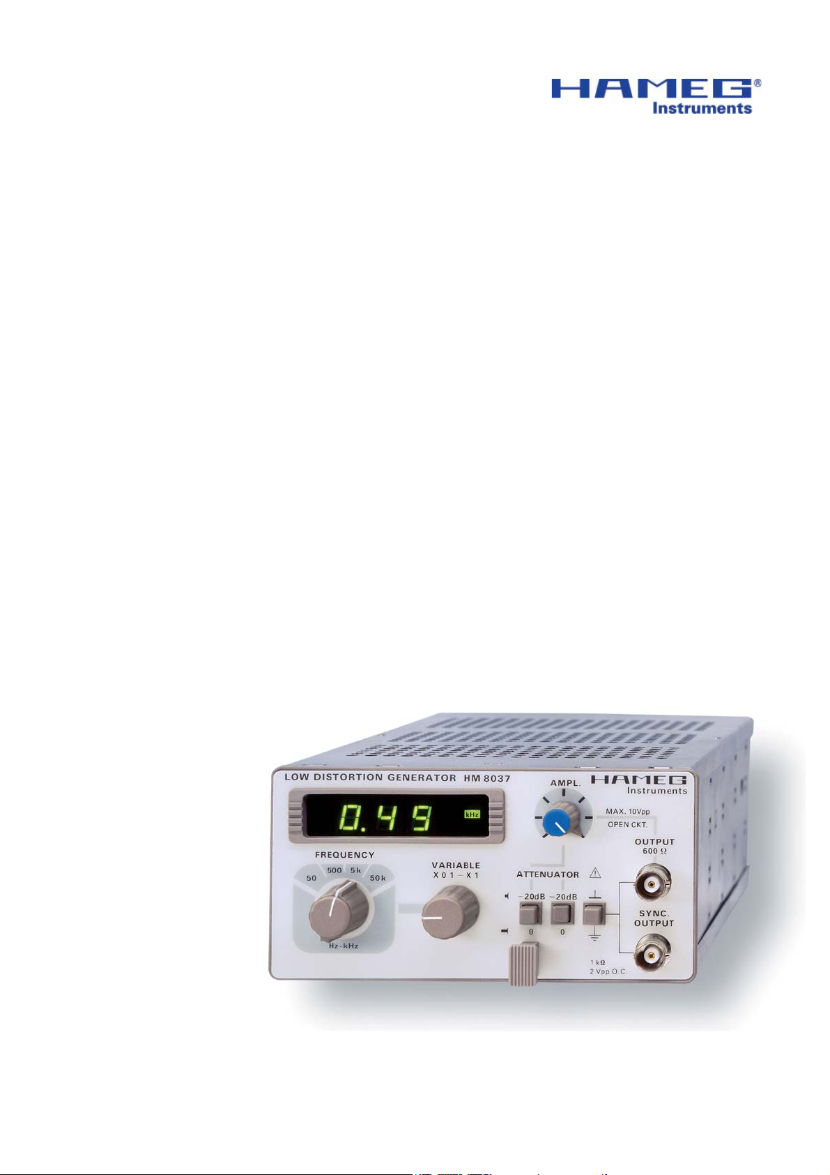
Low Distortion Generator
HM8037-2
Service-Manual
Page 2
General information regarding the CE marking
Hersteller HAMEG Instruments GmbH KONFORMITÄTSERKLÄRUNG
Manufacturer Industriestraße 6 DECLARATION OF CONFORMITY
Fabricant D-63533 Mainhausen DECLARATION DE CONFORMITE
Die HAMEG Instruments GmbH bescheinigt die Konformität für das Produkt
The HAMEG Instruments GmbH herewith declares conformity of the product
HAMEG Instruments GmbH déclare la conformite du produit
Bezeichnung / Product name / Designation:
Klirrarmer Sinus-Generator
Low Distrotion Generator
Générateur sinusoïdales à faible
distorsion
Typ / Type / Type: HM8037-2
mit / with / avec: HM8001/2
Optionen / Options / Options: –
mit den folgenden Bestimmungen / with applicable regulations / avec les
directives suivantes
EMV Richtlinie 89/336/EWG ergänzt durch 91/263/EWG, 92/31/EWG
EMC Directive 89/336/EEC amended by 91/263/EWG, 92/31/EEC
Directive EMC 89/336/CEE amendée par 91/263/EWG, 92/31/CEE
Niederspannungsrichtlinie 73/23/EWG ergänzt durch 93/68/EWG
Low-Voltage Equipment Directive 73/23/EEC amended by 93/68/EEC
Directive des equipements basse tension 73/23/CEE amendée par 93/68/CEE
Angewendete harmonisierte Normen / Harmonized standards applied / Normes
harmonisées utilisées
General information regarding the CE marking
Sicherheit / Safety / Sécurité
EN 61010-1: 1993 / IEC (CEI) 1010-1: 1990 A 1: 1992 / VDE 0411: 1994
EN 61010-1/A2: 1995 / IEC 1010-1/A2: 1995 / VDE 0411 Teil 1/A1: 1996-05
Überspannungskategorie / Overvoltage category / Catégorie de surtension: II
Verschmutzungsgrad / Degree of pollution / Degré de pollution: 2
Elektromagnetische Verträglichkeit / Electromagnetic compatibility / Compatibilité
électromagnétique
EN 61326-1/A1
Störaussendung / Radiation / Emission: Tabelle / table / tableau 4, Klasse / Class /
Classe B. Störfestigkeit / Immunity / Imunitee: Tabelle / table / tableau A1.
EN 61000-3-2/A14
Oberschwingungsströme / Harmonic current emissions / Émissions de courant
harmonique: Klasse / Class / Classe D.
EN 61000-3-3
Spannungsschwankungen u. Flicker / Voltage fl uctuations and fl icker / Fluctuations
de tension et du fl icker.
Datum/Date/Date
15.01.2001 Unterschrift / Signature / Signatur
Manuel Roth
Manager
HAMEG instruments fulfi ll the regulations of the EMC directive. The
conformity test made by HAMEG is based on the actual generic- and
product standards. In cases where different limit values are applicable,
HAMEG applies the severer standard. For emission the limits for
residential, commercial and light industry are applied. Regarding the
immunity (susceptibility) the limits for industrial environment have
been used.
The measuring- and data lines of the instrument have much infl uence
on emmission and immunity and therefore on meeting the acceptance
limits. For different applications the lines and/or cables used may
be different. For measurement operation the following hints and
conditions regarding emission and immunity should be observed:
1. Data cables
For the connection between instruments resp. their interfaces and
external devices, (computer, printer etc.) suffi ciently screened cables
must be used. Without a special instruction in the manual for a reduced
cable length, the maximum cable length of a dataline must be less than
3 meters and not be used outside buildings. If an interface has several
connectors only one connector must have a connection to a cable.
Basically interconnections must have a double screening. For IEEE-bus
purposes the double screened cables HZ72S and HZ72L from HAMEG
are suitable.
2. Signal cables
Basically test leads for signal interconnection between test point and
instrument should be as short as possible. Without instruction in the
manual for a shorter length, signal lines must be less than 3 meters
and not be used outside buildings.
Signal lines must screened (coaxial cable - RG58/U). A proper ground
connection is required. In combination with signal generators double
screened cables (RG223/U, RG214/U) must be used.
3. Infl uence on measuring instruments.
Under the presence of strong high frequency electric or magnetic fi elds,
even with careful setup of the measuring equipment an infl uence of
such signals is unavoidable.
This will not cause damage or put the instrument out of operation. Small
deviations of the measuring value (reading) exceeding the instruments
specifi cations may result from such conditions in individual cases.
HAMEG Instruments GmbH
2
Subject to change without notice
Page 3

Content
Declaration of Conformity 2
General information regarding the CE-marking 2
Function Generator
HM8037-2 4
Specifi cations 5
Control elements 6
Adjustment 6
Calibration 7
Circuit and layout diagrams 8
Subject to change without notice
3
Page 4
HM8037-2
50 kHz Low-Distortion Sine Wave
Generator
HM8037
Frequency range 5 Hz to 50kHz
A complete measurement system for AF measurement
equipment in combination with the HM8027
3-digit digital frequency display
High amplitude stability
Distortion factor ‹0.01 % (20Hz-10 kHz)
Output voltage 1.5 V
rms
into 600 Ω
Mainframe HM8001-2 required for operation
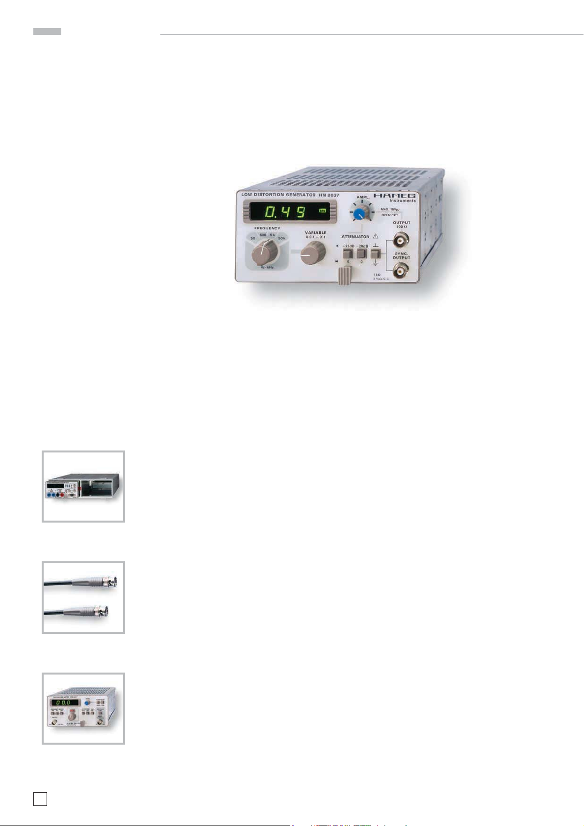
Distortion Meter HM8027
Mainframe HM8001-2
HZ33, HZ34
Test cable BNC/BNC
4
Subject to change without notice
Page 5

Specifications
HAMEG Instruments GmbH · Industriestr. 6 · D-63533 Mainhausen · Tel +49 (0)6182 800 0 · Fax +49(0) 6182 800 100 · www.hameg.com · info@hameg.com
A Rohde & Schwarz Company
50 kHz Low-Distortion Sine Wave Generator HM8037
Valid at 23 °C after a 30 minute warm-up period
Operating modes
Sine wave, continuous, amplitude-regulated
Frequency range:
5 Hz bis 50 kHz, 4 ranges
variable control 10:1, overlapping ranges
Frequency drift
(Frequency control in center position)
15 min. 0.08 % (50kHz range)
8 hrs. 0.6 % (50 kHz range)
15 min. 0.08 % (in all other ranges)
8 hrs. 0.5 % (in all other ranges)
Frequency display
3-digit, 7-segment LED display
Display accuracy: ±1 digit
Distortion factor
5 Hz - 20 Hz: max. 0.03 %
20 Hz -10 kHz: max. 0.01 %
1 kHz: typ. 0.005 %
10 kHz - 20 kHz: max. 0.03 %
20 kHz - 50 kHz: max. 0.05 %
Signal output (short-circuit proof)
Output voltage: 1.5 V into 600 Ω
Internal resistance: approx. 600 Ω
Amplitude flatness: max. ±0.2dB (5 Hz to 50 kHz)
Attenuation: min. 60 dB
2 fixed attenuators: each 20dB ± 0.2dB
variable control: 0 dB to 20 dB
Amplitude stability: 0.12 % (4 hrs.)
Synchronous output (short-circuit proof)
Output voltage: 2Vpp, sine wave
Internal resistance: ca. 1 kΩ
Miscellaneous
The outputs can be isolated from the case ground by pressing a key.
Power supply (from mainframe):
+5 V/120 mA
+15 V/30 mA
–15 V/30 mA
(∑ = 6.3 W)
Operating temperature: +10° C to +40° C
Max. relative humidity: 80% (without condensation)
Dimensions (W x H x D) (without 22-pole flat plug):
135 x 68 x 228 mm
Weight: approx. 0.65kg
Accessories supplied: Operator’s Manual
Optional accessories: HZ33/34 BNC Test Cable; HZ22 50
Ω feed-through
termination; HZ10 Silicone test leads
Subject to change without notice
5
Page 6

Controls elements
Control elements
DISPLAY (7-segment LED + LED)
3-digit frequency meter. Accuracy ±1 digit. LED indicators
for Hz and kHz.
FREQUENCY (4-position rotary switch)
Frequency coarse adjustment from 5 Hz to 50 kHz in 4 de-
cade steps.
VARIABLE (adjusting knob)
Continous frequency adjustment.
Overlapping the ranges selected with
from x0,1 to x1 of selected range.
–20 dB Attenuators (pushbuttons)
Two fi xed attenuators of –20 dB. They can be used separa-
tely. When all buttons are pressed, a total attenuation of
–40 dB is obtained. Including the amplitude control
max. attenu ation amounts to –60 dB (factor: 1000).
GROUND (pushbutton)
When pressing, signal ground and chassis (earth) are not
connected toget her; when released, signal ground and
chassis are connected with each other.
SYNCHRONIZING OUTPUT
(BNC connector)
Short-circuit-proof trigger signal output of same phase
and amplitude as
Output impedance is 1 k
. Output amplitude is 2 Vpp open circuit.
.
. Setting range is
, the
Adjustment
1 ADJUSTMENT OF VREG
(CONTROL LOOP ERROR VOLTAGE)
a) Connect a DC multimeter (10V range) or an oscil-
loscope between REG and GND (CN6 connector).
b) Switch to 50 kHz frequency range.
Adjust the frequency control in order to have 50.0 kHz.
c) Switch to 500 Hz frequency range.
Note the voltage between REG and GND.
d) Switch to 50 kHz frequency range.
Adjust VC1 in order to have the same potential mea-
sured in step 3).
e) Repeat step 2 to 4.
2 ADJUSTMENT OF OUTPUT VOLTAGE
a) Adjust AMP control for maximum signal.
b) Adjust VARIABLE control for minimum frequency,
5 kHz r ange.
c) Connect an AC multimeter to OUTPUT 600
d) Adjust RV3 to get 3.250 V
rms
.
.
600 OUTPUT (BNC connector)
Short-circuit-proof signal output of generator. Output im-
pedance 600
.
AMPLITUDE (adjusting knob)
Continous adjustment of output amplitude from 0dB to
–20 dB when output
6
Subject to change without notice
is terminated with 600 .
3) VERIFICATIONS
a) Set the instrument to 5 kHz range.
b) Connect an oscilloscope to the OUTPUT 600
c) Check the signal stability for all frequencies.
d) Check the presence of a sine signal.
e) Check the isolation of the BNC from the earth.
.
Page 7

Calibration
Calibration
VISUAL CONTROL
Font panel, buttons
ELECTRICAL CONTROL
a) OUTPUT AMPLITUDE:
– Connect the multimeter (HM8012, 50 V
PUT 600Ω
– Select 5 kHz frequency range, VARIABLE control to the
left, AMPL. control to the right
– Output voltage must be between 3.100 and 3.300 V
– Set AMPL. Control to the left. Output voltage must be
below 0.320 V
rms
– Connect the multimeter to the SYNC OUTPUT. Reading
voltage must be between 0.6 and 0.750 V
b) FREQUENCY LIMITS
– Select 50 kHz frequency range
– VARIABLE control to the left: frequency readings be-
low 4.9
– VARIABLE control to the right: frequency readings
above 50.5
) to the OUT-
AC
rms
– Turn slowly the AMPL. control from right to left. The signal
must be a sine signal without visual distorsion
– Set the AMPL. control to the right. Push the fi rst 20 dB
button. Set the oscilloscope for 10 X sensitivity. The signal
must have 6 divisions amplitude.
– Push the second 20 dB button and release the fi rst one. The
amplitude of the signal must be the same.
– Check the presence of the SYNC signal.
ISOLATION KEY CHECKING
Check the isolation between ground and earth with a component tester
rms
c) DISTORSION LEVELS (with KROHN HITE)
– Check the VARIABLE control linearity. AMPL. Control
to the right, 5 kHz range
VARIABLE KROHN-HITE MAX (%) TYPICAL (%)
1.00 kHz 1-10 kHz range
1.20 kHz
1.4 0 kHz
1.60 kHz
1.80 kHz 0.01 0.003
2.00 kHz
2.20 kHz
2.40 kHz
2.60 kHz
2.80 kHz
HM8037 KROHN Variable Max. TYPICAL
HITE
RANGE RANGE (%) (%)
50 Hz 10 - 100 20 Hz
500 Hz 10-100 left
500 Hz 100 - 1k 100 Hz 0.01 0.003
50 kHz 100 - 1k left
50 kHz 10 - 110k 10 kHz
50 kHz 10 - 110k 20 kHz 0.03 0.0035
50 kHz 10- 110k right 0.05 0.015
OUTPUT ATTENUATORS CHECK
– Connect a 600Ω load and an oscilloscope to the OUTPUT
600Ω
– Adjust the oscilloscope in order to have a 6 divisions am-
plitude signal
– Check that the amplitude is stable on all frequency ranges,
for all positions of the VARIABLE control potentiometer.
Subject to change without notice
7
Page 8

Circuit and layout diagrams
8
Subject to change without notice
Page 9

Circuit and layout diagrams
Subject to change without notice
9
Page 10

Circuit and layout diagrams
10
Subject to change without notice
Page 11

Circuit and layout diagrams
Subject to change without notice
11
Page 12

Circuit and layout diagrams
12
Subject to change without notice
Page 13

Circuit and layout diagrams
Subject to change without notice
13
Page 14

Notes
14
Subject to change without notice
Page 15

Notes
Subject to change without notice
15
Page 16

Oscilloscopes
Spectrum Analyzer
Power Supplies
Modular System
8000 Series
Programmable Instruments
8100 Series
authorized dealer
4S-8037- 02E0
www.hameg.de
Subject to change without notice
4S-8037-02E0 / 04-11-2005-gw HAMEG Instruments GmbH
© HAMEG Instruments GmbH Industriestraße 6
A Rohde & Schwarz Company D-63533 Mainhausen
® registered trademark Tel +49 (0) 61 82 800-0
DQS-Certifi cation: DIN EN ISO 9001:2000 Fax +49 (0) 61 82 800-100
Reg.-Nr.: 071040 QM sales@hameg.de
 Loading...