

Page 1
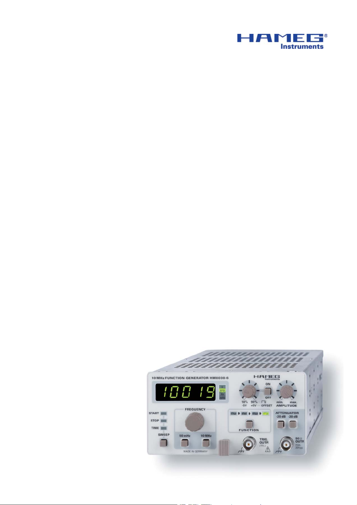
Function Generator
HM8030-6
Service-Manual
Page 2
General information regarding the CE marking
Hersteller HAMEG Instruments GmbH KONFORMITÄTSERKLÄRUNG
Manufacturer Industriestraße 6 DECLARATION OF CONFORMITY
Fabricant D-63533 Mainhausen DECLARATION DE CONFORMITE
Die HAMEG Instruments GmbH bescheinigt die Konformität für das Produkt
The HAMEG Instruments GmbH herewith declares conformity of the product
HAMEG Instruments GmbH déclare la conformite du produit
Bezeichnung / Product name / Designation:
Funktionsgenerator
Function generator
Générateur de fonctions
Typ / Type / Type: HM8030-6
mit / with / avec: HM8001-2
Optionen / Options / Options:
mit den folgenden Bestimmungen /
with applicable regulations /
avec les directives suivantes
EMV Richtlinie 89/336/EWG ergänzt durch 91/263/EWG, 92/31/EWG
EMC Directive 89/336/EEC amended by 91/263/EWG, 92/31/EEC
Directive EMC 89/336/CEE amendée par 91/263/EWG, 92/31/CEE
Niederspannungsrichtlinie 73/23/EWG ergänzt durch 93/68/EWG
Low-Voltage Equipment Directive 73/23/EEC amended by 93/68/EEC
Directive des equipements basse tension 73/23/CEE amendée par 93/68/CEE
Angewendete harmonisierte Normen /
Harmonized standards applied /
Normes harmonisées utilisées
General information regarding the CE marking
Sicherheit / Safety / Sécurité:
EN 61010-1: 1993 / IEC (CEI) 1010-1: 1990 A 1: 1992 / VDE 0411: 1994
EN 61010-1/A2: 1995 / IEC 1010-1/A2: 1995 / VDE 0411 Teil 1/A1: 1996-05
Überspannungskategorie / Overvoltage category / Catégorie de surtension: II
Verschmutzungsgrad / Degree of pollution / Degré de pollution: 2
Elektromagnetische Verträglichkeit / Electromagnetic compatibility / Compatibilité
électromagnétique
EN 61326-1/A1
Störaussendung / Radiation / Emission: Tabelle / table / tableau 4, Klasse / Class
/ Classe B.
Störfestigkeit / Immunity / Imunitee: Tabelle / table / tableau A1.
EN 61000-3-2/A14
Oberschwingungsströme / Harmonic current emissions / Émissions de courant
harmonique: Klasse / Class / Classe D.
EN 61000-3-3
Spannungsschwankungen u. Flicker / Voltage fl uctuations and fl icker /
Fluctuations de tension et du fl icker.
Datum/Date/Date
22.07.2004
Unterschrift / Signature /Signatur
Manuel Roth
Manager
HAMEG instruments fulfi ll the regulations of the EMC directive. The
conformity test made by HAMEG is based on the actual generic- and
product standards. In cases where different limit values are applicable,
HAMEG applies the severer standard. For emission the limits for
residential, commercial and light industry are applied. Regarding the
immunity (susceptibility) the limits for industrial environment have
been used.
The measuring- and data lines of the instrument have much infl uence
on emmission and immunity and therefore on meeting the acceptance
limits. For different applications the lines and/or cables used may
be different. For measurement operation the following hints and
conditions regarding emission and immunity should be observed:
1. Data cables
For the connection between instruments resp. their interfaces and
external devices, (computer, printer etc.) suffi ciently screened cables
must be used. Without a special instruction in the manual for a reduced
cable length, the maximum cable length of a dataline must be less than
3 meters and not be used outside buildings. If an interface has several
connectors only one connector must have a connection to a cable.
Basically interconnections must have a double screening. For IEEE-bus
purposes the double screened cables HZ72S and HZ72L from HAMEG
are suitable.
2. Signal cables
Basically test leads for signal interconnection between test point and
instrument should be as short as possible. Without instruction in the
manual for a shorter length, signal lines must be less than 3 meters
and not be used outside buildings.
Signal lines must screened (coaxial cable - RG58/U). A proper ground
connection is required. In combination with signal generators double
screened cables (RG223/U, RG214/U) must be used.
3. Infl uence on measuring instruments.
Under the presence of strong high frequency electric or magnetic fi elds,
even with careful setup of the measuring equipment an infl uence of
such signals is unavoidable.
This will not cause damage or put the instrument out of operation. Small
deviations of the measuring value (reading) exceeding the instruments
specifi cations may result from such conditions in individual cases.
HAMEG Instruments GmbH
2
Subject to change without notice
Page 3

Content
Declaration of Conformity 2
General information regarding the CE-marking 2
Function Generator HM8030-6 4
Specifi cations 5
Control elements 6
Adjustment 7
Circuit and layout diagrams 9
Subject to change without notice
3
Page 4
HM8030-6
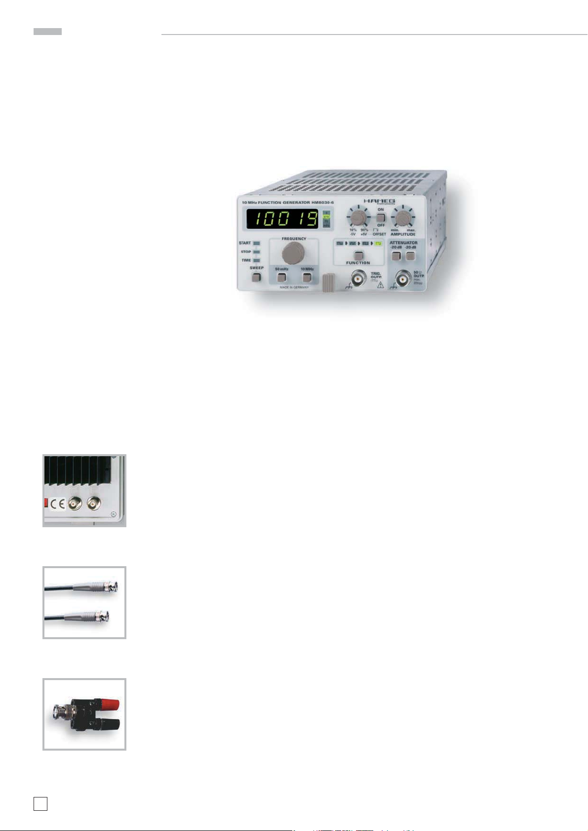
10 MHz Function Generator
HM8030-6
Frequency range 50 mHz to 10 MHz
High signal purity and amplitude stability
Distortion factor ‹ 0.5 % up to 1 MHz
Output voltage 20 Vpp(10 Vppinto 50 Ω)
Surge- and short-circuit-proof output
Rise and fall time typ. 15 ns
Internal and external sweep
Pulse width adjustment
Highly accurate digital frequency display
Mainframe HM8001-2 required for operation
HZ20 Connector
BNC to 4mm socket
Option HO801
HZ33, HZ34
Test cable BNC/BNC
4
Subject to change without notice
Page 5

Specifications
Accessories supplied: Operator’s Manual
Optional accessories: HZ33/HZ34 BNC Test Cable, HZ22 50Ω feed-through
terminal, HZ10 Silicone test leads
10 MHz Function Generator HM8030-6
Valid at 23 °C after a 30 minute warm-up period
Operating modes
Sine, square, triangle, pulse; free running, internal sweep or external
frequency modulation, with or without DC offset
Frequency ranges
0.05 Hz to 10 MHz in 8 ranges, variable: x 0.09 to x 1.1 (12:1)
Frequency drift: ‹ 0.5 % /hr or 0.8 %/24 hrs. at constant
ambient temperature
Waveform characteristics
Sine wave distortion
0.05 Hz to 1 MHz: max. 0.5 %
1 MHz to 10 MHz: max. 5%
Square wave rise time: typ. 15 ns
Overshoot: ‹ 5 % (for termination into 50 Ω)
Triangle non-linearity: ‹ 1 % (to 100 kHz)
Displays
Frequency: 5-digit, 7-segment LED, each 8 x 5 mm
Accuracy:
up to 5 Hz: ± (1 % + 3 digits)
5 Hz to 10 MHz: ± (5 x 10⁻⁵+ 1 digit)
LED indicators for mHz, Hz, kHz and sec
Outputs
Signal output: short-circuit proof,
protected against ext. voltage up to ± 45 VDCmax. (30 sec.)
Impedance: 50 Ω
Output voltage: 10 Vppinto 50 Ω load; 20 V
pp
(open circuit)
Attenuation: max. 60 dB
2 attenuators: each 20 dB ± 0.2 dB
Variable: 0 to 20 dB
Amplitude error: (sine wave/triangle)
0.05 Hz to 0.5 MHz: max. 0.2 dB
0.5 MHz to 10 MHz: max. 0.5 dB
DC offset: variable (on/off, except pulse function)
into 50 Ω load: max. ±2.5 V
in open circuit: max. ±5 V
Trigger output: square wave synchronous to
signal output, approx. +5V/TTL
FM input
(VCF, BNC connector on rear panel of HM8001-2 and option HO801)
Frequency deviation: approx. 1 : 100
Input impedance: 6 kΩ II 25pF
Input voltage: max. ± 30 V
Internal sweep
Sweep speed: 20 ms to 15 s
Sweep range: approx. 1:100
Miscellaneous
Power supply +5V/200mA
(from mainframe): +16V/300mA
-16V/250mA
(∑=9.8 W).
Operating temperature: +10°C to + 40°C
Max. relative humidity: 80 % (without condensation)
Dimensions (W x H x D) (without 22-pole flat plug):
135 x 68 x 228 mm
Weight: approx. 0.80kg
HM8030-6E/140705/ce · Subject to alterations · © HAMEG Instruments GmbH · ® Registered Trademark · DQS-certified in accordance with DIN EN ISO 9001:2000, Reg.-No.: DE-071040 QM
HAMEG Instruments GmbH · Industriestr. 6 · D-63533 Mainhausen · Tel +49 (0) 6182 800 0 · Fax +49 (0)6182 800 100 · www.hameg.com · info@hameg.com
A Rohde & Schwarz Company
www.hameg.com
Subject to change without notice
5
Page 6
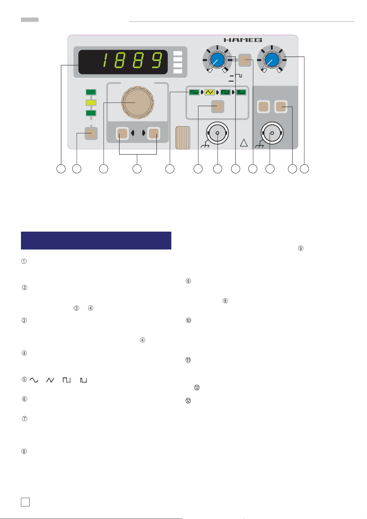
Control elements
10 MHz FUNCTION GENERATOR HM8030-6
FREQUENCY
START
STOP
TIME
SWEEP
50 mHz 10 MHz
MADE IN GERMANY
s
kHz
Hz
mHz
10 % 9 0 %
-5 V + 5 V
FUNCTION
Instruments
OFF
OFFSET
TRIG.
OUTP.
(TTL)
ON
ATTENUATOR
!
min. max.
AMPLITUDE
-20 dB -20 dB
50 Ω
OUTP.
max.
20Vpp
1 2 3 4 5 6 7 8 9 10 11 12
Control elements
DISPLAY (7 segment LED)
5-digit frequency meter. LED indicators for mHz, Hz, kHz
and s
SWEEP (push button) and SWEEP- Indication (LEDs)
Button activates internal sweep generator. The LEDs indi-
cate the function chosen with the SWEEP-Button. Settings
are changed with
FREQUENCY (adjustment knob)
Continuous and linear frequency fi ne ad-justment, with the
setting range from 0.09 to 1.1 (approx 0.045 to 1.1 in 10 MHzrange) overlapping the ranges selected with
FREQUENCY (2 pushbuttons)
Frequency range selection from 50 mHz to 10 MHz in 8 de-
cade steps.
– (LED s)
Indication of selected function.
FUNCTION – (pushbutton)
Mode selection: Triangle, Sine, Square, Pulse and Off.
TRIGGER OUTPUT (BNC connector)
This short-circuit-proof output supplies a square signal in
synchronism with the output signal. It is T TL compatible
and has a duty-factor of approx. 50%.
or .
max. offset voltage is ±5V (o.c.) or ±2.5V respectively when
terminated into 50Ω. The offset voltage is available to all
functions except for pulse and activated by
. In operation
mode OFF (no function activated) it can be used separatey.
In pulse mode the pulse width is set with this control from
10% to 90%.
ON (pushbutton)
Activates the offset function except in pulse mode. If the
ON-button is pushed in pulse mode, pulse width is set with
the control
from 10% to 90%. In OFF-position the fi xed
pulse width amounts to 50%.
50Ω OUTPUT (BNC connector)
Short-circuit proof signal output of the generator. The
output impedance is 50Ω and the max. output amplitude
is 20 V
(o.c.) or 10 Vpp respectively when terminated into
pp
50Ω.
–20dB, –20bB (pushbutton)
Two fi xed attenuators, 20dB each. They can be used se-
parately. When both pushbuttons are activated, a total attenuation of 40dB results. Including the amplitude control
, the max. attenuation amounts to 60dB (factor 1000).
AMPLITUDE (adjustment knob)
Continuous adjustment of the output ampli-tude from 0 to
–20dB terminated into 50Ω.
OFFSET (adjustment knob)
Adjustment of the positive or negative offset voltage. This
DC voltage can be super-imposed on the output signal. The
6
Subject to change without notice
Page 7

Adjustment
Please observe the correct sequence of steps!
Measuring equipment required:
– Digital Multimeter ( HM8012 or similar)
– Frequency counter (HM8021 or similar)
– Distortion meter (HM8027 or similar)
– Oscilloscope (HM1507 or similar)
1) Turning ser vice mode on
a) For a ctivat ing s er vi ce mo de pus h bot h but tons „ 50 mHz“
and „10MHz“ simultaneously and switch on the
HM8030.
b) If the EPROM is empty or if the HM8030 is new, the dis-
pla y w il l sh ow „E “, oth er wis e „F 3 .1“. Pu sh butto n „FUN CTION“.
c) If the display shows „XXX3“ (X = any fi gure, fi gure ‚3’
blinking), turn off the instrument.
2) Switches and controls
These settings must be kept constant during the whole ad-
justment procedure!
a) Open the top cover of the instrument.
b) Set OFFSET control to center position.
c) Button OFFSET deactivated.
d) Set AMPLITUDE control the right stop.
e) Buttons ATTENUATOR deactivated.
f) Push button SWEEP as often as needed to extinguish
the START, STOP and TIME LEDs.
Adjustment
6) OUTPUT Offset
a) Connect HM8012 (measuring range: 500 mV
pass fi lter to OUT.
b) Set HM8030 to triangle function with f = 5250 Hz.
c) Adjust 0 mV ±1 mV with VR111.
7) Distortion
a) Connect HM8027 (20k Frequency Range) to OUT.
b) Set HM8030 to sine function with f = 5250 Hz.
c) Set HM8027 (settings: 100% CAL) with the blue control
to 100, than switch to 10%.
d) Ad just the dis torti on f ac tor to less than 0.3 % by a lte rna-
tely adjusting VR108 and VR109.
e) If this adjustment is not possible, return to step 4) be-
cause the duty cycle was not correctly adjusted.
8) Square 1
a) Connect oscilloscope HM1507 (settings: 1V/div, 100μs/
div) with 50Ω to OUT.
b) Set HM8030 to triangle function with f = 5250 Hz.
c) Adjust VAR on the oscilloscope so that the amplitude of
the signal equals to 6 div.
d) Set HM8030 to square function with f = 5250 Hz.
e) Adjust VR105, VR107 and VR110 so that the amplitude of
the square signal amounts to 6 div.
f) Repeat step e) with f = 52,5 kHz.
9) Square 2
a) Connect oscilloscope HM1507 (settings: 1V/div, 50ns/div)
with a 50Ω load at OUT.
b) Set HM8030 to square function with f = 5250kHz.
c) Adjust VC102 and VC104 so that the amplitude of the
square signal equals to 6 div.
) with low
DC
3) Internal triangle generator
a) Set HM8030 to triangle function with f = 5250 Hz.
b) Connect HM8012 (measuring range: 500 mV
DC
probe (with the low pass fi lter shown) at PT100.
c) Adjust 0 mV ±1 mV with VR103.
d) Connect HM8012 (measuring range: 500 mV
AC
probe (without low pass fi lter) at PT100.
e) Adjust 577,3 mV ±1 mV with VR102.
f) As the settings are interacting, repeat steps b) to e) as
often as is necessary for an optimum result.
4) Duty cycle 1
a) Connect HM8021 (function: pulse) to OUT.
b) Set HM8030 to square function with f = 52,50 kHz.
c) Adjust VR101 so that the positive pulse width is equal to
the negative pulse width.
d) Set HM8030 to square function with f = 4,75 kHz .
e) Adjust VR104 so that the positive pulse width is equal to
the negative pulse width.
f) As the settings are interacting, repeat steps b) to e) as
often as is necessary for an optimum result.
) with a
) with a
10) Triangle
a) Connect oscilloscope HM1507 (settings: 1V/div, 50ns/div)
with a 50Ω load at OUT.
b) Set HM8030 to triangle function with f = 7000 kHz.
c) Adjust VC101 so that the amplitude of the triangle signal
equals to 6 div.
11) Duty cycle of pulse
a) Connect HM8021 (function: pulse) to OUT.
b) Set HM8030 to pulse function with f = 5250 Hz.
c) Adjust VR1 so that the positive pulse width is equal to
the negative pulse width.
5) Duty cycle 2
a) Connect HM8021 (function: pulse) to OUT.
b) Set HM8030 to square function with f = 475 Hz.
c) Adjust VR106 so that the positive pulse width is equal to
the negative pulse width.
Subject to change without notice
7
Page 8

Adjustment
y
)
)
)
h
e
Adjustment HM8030-6
30. November 2004
1) Turning service mode on
a) For activating service mode push both buttons „50mHz“ and „10MHz“ simultaneously and switch on the HM8030.
.
a) If the EPROM is empty or if the HM8030 is new, the display will show „E“, otherwise „F 3.1“. Push button „FUNC-
TION“. If the display shows „XXX3“ (X = any figure, figure ‚3’ blinking), turn off the instrument.
2) Switches and controls - These settings must be kept constant during the whole adjustment!
a) Open the top cover of the instrument.
b) Set OFFSET control to center position.
c) Button OFFSET deactivated.
d) Set AMPLITUDE control to the right stop.
e) Buttons ATTENUATOR deactivated.
f
Push button SWEEP as often as is needed to extinguish the START, STOP and TIME LEDs.
10) Triangle
a) Connect oscilloscope HM1507 (settings: 1V/div,
50ns/div) with a 50 load at OUT.
b) HM8030 - traingle function - f = 7000kHz.
c) Adjust VC101 so that the amplitude of the triangl
signal equals to 6 div.
5) Duty cycle 2
a) Connect HM8021 (function: pulse) to OUT.
b) Set HM8030 to square function with f = 475Hz.
c) Adjust VR106 so that the positive pulse width
is equal to the negative pulse width.
11) Duty cycle of pulse
a) Connect HM8021 (function: pulse) to
OUT.
b) HM8030 - pulse function - f = 5250Hz.
c) Adjust VR1 so that the positive pulse
VR106
width is equal to the negative pulse
width.
4) Duty cycle 1
a) Connect HM8021 (function: pulse) to OUT.
b) HM8030 - square function - f = 52,50kHz.
c) Adjust VR101 the pos. pulse width is equal to neg.
pulse width.
d) HM8030 - square function - f = 4,75kHz .
e) Adjust VR104 so that the positive pulse width is equa
to the negative pulse width.
f
As the settings are interacting, repeat steps b) to e
VR101
VR104
VR103
VC101
PT100
VR102
3) Internal triangle generator
a) HM8030 - triangle function - f = 5250Hz.
b) HM 8012 (500mV
) with a probe (with low-
DC
pass filter) at PT100.
c) Adjust 0mVr 1mV with VR103.
d) Connect HM8012 (500mV
) with a probe
AC
(without lowpass filter) at PT100.
e) Adjust 577,3mVr 1mV with VR102.
f) As settings are interacting, repeat steps b) - e)
as often as is necessar
for an optimum result.
8) Square 1
a) Connect oscilloscope HM1507 (set-
VR1
VR109
tings: 1V/div, 100μs/div) with 50
to OUT.
b) Set HM8030 to triangle function
VR105
VR110
VC104
with f = 5250Hz.
c) Adjust VAR on the oscilloscope so
that the amplitude of the signal
equals to 6 div.
d) Set HM8030 to square function
with f = 5250Hz.
VC102
e) Adjust VR105, VR107 and VR110
so that the amplitude of the square
signal equals to 6 div.
f) Repeat step e) with f = 52,5kHz.
9) Square 2
a) Connect oscilloscope HM1507 (settings: 1V/div, 50ns/div) with a 50
load at OUT.
b) Set HM8030 to square function with f = 5250kHz.
c) Adjust VC102 and VC104 so that the amplitude of the square signal
equals to 6 div.
8
Subject to change without notice
VR106
VR111
VR107
6) OUTPUT Offset
a) Connect HM8012 (500mV
DC
) with
lowpass filter to OUT.
b) HM8030 - triangle function f = 5250Hz.
7) Distortion
a) Connect HM8027 (20k Frequency
Range) to OUT.
b) HM8030 - sine function - f = 5250Hz.
c) Set HM8027 (settings: 100% CAL) wit
the blue control to 100, than switch to
10%.
d) Adjust the distortion factor to less than
0.3% by alternately adjusting VR108
and VR109.
e) If this adjustment is not possible, return
to step 4) because the duty cycle was
not correctly adjusted.
Page 9

Circuit and layout diagrams
Subject to change without notice
9
Page 10

Circuit and layout diagrams
10
Subject to change without notice
Page 11

Circuit and layout diagrams
Subject to change without notice
11
Page 12

Circuit and layout diagrams
12
Subject to change without notice
Page 13

Circuit and layout diagrams
Subject to change without notice
13
Page 14

Circuit and layout diagrams
14
Subject to change without notice
Page 15

Circuit and layout diagrams
Subject to change without notice
15
Page 16

Circuit and layout diagrams
16
Subject to change without notice
Page 17

Circuit and layout diagrams
Subject to change without notice
17
Page 18

Circuit and layout diagrams
18
Subject to change without notice
Page 19

Circuit and layout diagrams
Subject to change without notice
19
Page 20

Oscilloscopes
Spectrum Analyzer
Power Supplies
Modular System
8000 Series
Programmable Instruments
8100 Series
authorized dealer
4S-8030- 06E0
www.hameg.de
Subject to change without notice
4S-8030-06E0 / 07-11-2005-gw HAMEG Instruments GmbH
© HAMEG Instruments GmbH Industriestraße 6
A Rohde & Schwarz Company D-63533 Mainhausen
® registered trademark Tel +49 (0) 61 82 800-0
DQS-Certifi cation: DIN EN ISO 9001:2000 Fax +49 (0) 61 82 800-100
Reg.-Nr.: 071040 QM sales@hameg.de
 Loading...