

Page 1
Blank Module
HM800
Manual
English
Page 2
General information regarding the CE marking
General information regarding the
CE marking
DECLARATION OF
CONFORMITY
Manufacturer HAMEG Instruments GmbH
Industriestraße 6
D-63533 Mainhausen
The HAMEG Instruments GmbH herewith
declares conformity of the product
Product name : Blank Module
Typ e : HM 8 0 0
with: HM8001-2
Options: –
with applicable regulations
EMC Directive 8 9/ 33 6/ EEC amended by
91/263/ EWG, 92/31/ EEC
Low-Voltage Equipment Directive 73/23/ EEC
amended by 93 /68/EEC
Harmonized st andards applied
Safety
EN 61010-1:2001 / (IEC 61010-1:2001)
Overvoltage category: II
Degree of pollution : 2
Electromagnetic compatibility
EN 61326-1/A1
Radiation: table 4 ; Class B
Immunity: table A1
EN 61000-3-2/A14
Harmonic current emissions : Class D
EN 61000-3-3
Volt ag e fl uctuations and fl icker
Date: 22.07.2004
HAMEG instruments fulfi ll the regulations of the
EMC directive. The conformity test made by HAMEG is based on the actual generic and product
standards. In cases where different limit values
are applicable, HAMEG applies the strictest
standard. For emission the limits for residential,
commercial and light industry are applied. Regarding the immunity (susceptibility) the limits
for industrial environment have been used.
The measuring and data lines of the instrument
have much infl uence on emission and immunity
and therefore on meeting the acceptance limits.
For different applications the lines and/or cables
used may be different. For measurement operation the following hints and conditions regarding
emission and immunity should be observed:
1. Data cables
For the connection between instruments resp.
their interfaces and external devices, (computer,
printer etc.) suffi ciently screened cables must
be used.
Maximum cable length of data lines must not exceed 3 m. The manual may specify shorter lengths.
If several interface connectors are provided only
one of them may be used at any time.
Basically interconnections must have a double
screening. For IEEE-bus purposes the double
screened cable HZ72 from HAMEG is suitable.
2. Signal cables
Basically test leads for signal interconnection
between test point and instrument should be
as short as possible. Without instruction in the
manual for a shorter length, signal lines must be
less than 3 meters long.
Signature
Manuel Roth
Manager
2
Subject to change without notice
Signal lines must be screened (coaxial cable - RG58/
U). A proper ground connection is required. In combination with signal generators double screened
cables (RG223/U, RG214/U) must be used.
3. Infl uence on measuring instruments.
In the presence of strong high frequency electric
or magnetic fi elds, even with careful setup of the
measuring equipment an infl uence can not be
excluded.
Page 3

Content
This will not cause damage or put the instrument
out of operation. Small deviations of the measuring value (reading) exceeding the instrument‘s
specifi cations may result from such conditions
in some cases.
HAMEG Instruments GmbH
Declaration of conformity 2
General information regarding the
CE marking 2
Blank Module HM800 4
Important hints 5
Safety 5
Operating conditions 5
Warranty and Repair 5
Maintenance 6
Operation of the blank module 6
Interface board for HM800 7
HM8001-2 Interface Specifi cation 8
Subject to change without notice
3
Page 4
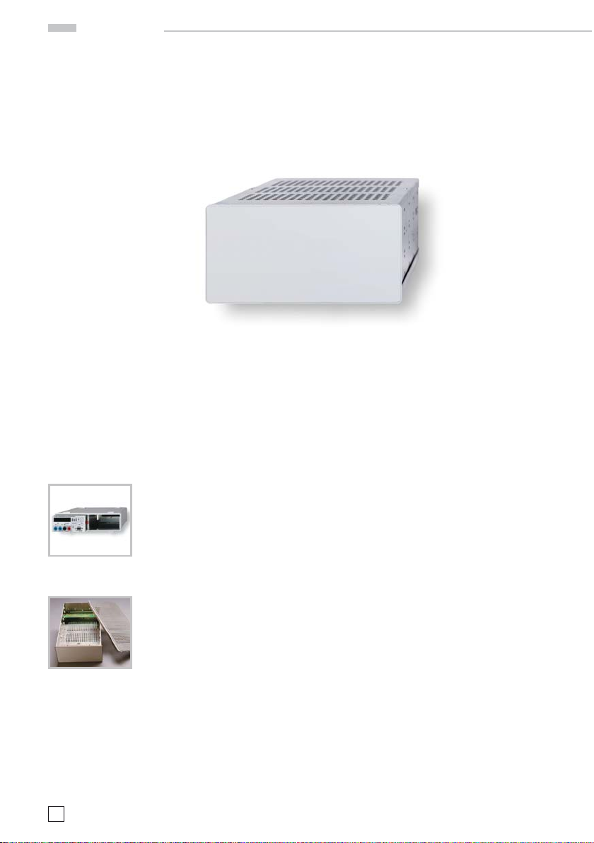
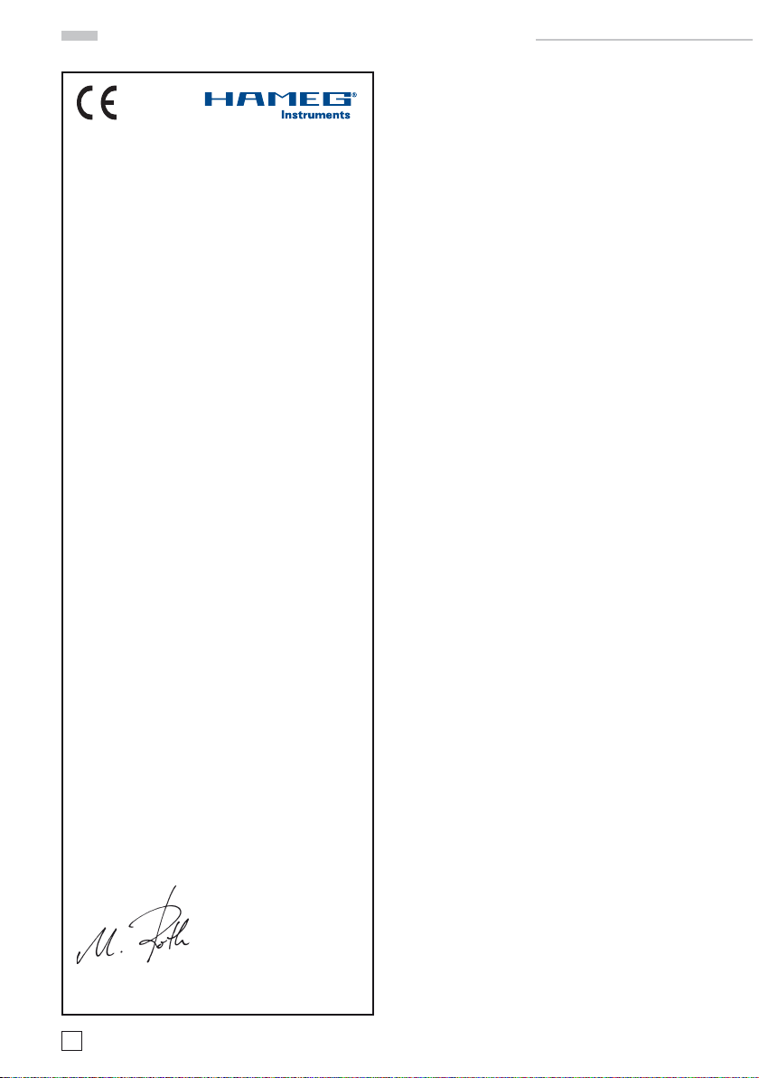
HM800
Module for customized instrument construction
Guide rails for mounting circuit boards at 4 different levels
Plastic front panel for easy processing
Power is supplied by the mainframe HM8001-2
Available supply voltages, load capability
see datasheet of HM800
Open blank module
Mainframe HM8001-2
required for operation
Blank Module
HM800
HM800
4
Subject to change without notice
Page 5

Important hints
Important hints
The operator is requested to read the following
instr uctions and th ose of the mainfr ame HM80 012 carefully, to avoid any operating errors and
mistakes and in order to become acquaint with
the module.
After unpacking the blank module, check for any
mechanical damage or loose parts inside. Should
there be any transportation damage, inform the
supplier immediately and do not put the module
into operation. This plug-in module is primarily
intended for use in conjunction with the mainframe HM8001-2. When incorporating it into other
s ys tem s, th e m odul e s ho uld o nl y b e op er at ed wi th
the specifi ed supply voltages.
Safety
This instrument has been designed and tested in
accor dance with IEC Publication 1010-1, Safety
require m ents for electric al equipment for m easurement, control, and laboratory use. It corresponds as well to the CENELEC regulations EN
61010-1. All case and chassis par ts are connected
to the safet y ear th conductor. Corresponding to
Safety Class 1 regulations (three-conductor AC
power cable). Without an isolating transformer,
the instrument's power cable must be plugged
into an approved three-contact electrical outlet,
which meets International Ele ctrotechnic al Commission (IEC) safety standards.
Warning!
Any interruption of the protective conductor
inside or outside the instrument or disconnection of the protective earth terminal is
likely to render the instrument dangerous.
Intentional interruption is prohibited.
The is trument must b e disconnected and se cured
agains t unintentional op eration if the re is any suggestion that safe operation is not possible.
This may occur:
– if the instrument shows visible damage,
– if the instrument has loose par ts.
– if the instrument does not function,
– after long storage under unfavourable circ-
umstances (e.g. outdoors or in moist environments),
– after excessive transportation stress (e.g. in
poor packaging).
When removing or replacing the metal case, the
instrument must be completely disconnected
from the mains supply. If any measurement or
calibration procedures are necessary on the
opene d-up instrument, th ese must only b e carried
out by qualifi ed personnel acquainted with the
danger involved.
Symbols marked on equipment
ATTENTION refer to manual.
DANGER! High voltage.
Protective ground (earth) terminal.
Operating conditions
The ambient temperatur e range during oper ation
should be between +5°C and +40 °C and should
not exceed –20 °C or +70 °C during transpor t or
storage. The operational position is optional, however, the ventilation holes on the HM8 001-2 and on
the plug-in modules must not be obstructed.
Warranty and Repair
HAMEG instr uments are sub jected to a stri ct quality control. Prior to leaving the factor y, each instrument is burnt-in for 10 hours. By intermittent
oper ation during this per iod almost al l defects are
detected. Following the burn-in, each instrument
is tested for function and quality, the specifi cations
are checked in all operating modes; the test gear
is calibrated to national standards.
The warranty standards applicable are those of
the country in which the instrument was sold.
Reclamations should be directed to the dealer.
Only valid in EU countries
In order to speed reclamations customers in EU
countries may also contact HA MEG directly. Also,
after th e warrant y expired , the HAMEG ser vice will
be at your disposal for any repairs.
Subject to change without notice
5
Page 6

Important hints
Return material authorization (RMA):
Prior to returning an instrument to HAMEG ask
for a RMA number either by internet (http://www.
hameg.com) or fax. If you do not have an original
shipping car ton, you may obtain one b y calling the
HAMEG service dept (+49-6182-800-500) or by
sending an email to service@hameg.com.
Maintenance
The mos t important characteristic s of the instruments should be periodically checked according to
the instructions provided in the sections “Operational check and alignment procedure“. To obtain
the nor mal operatin g temperatur e, the mainfra me
w ith in se rt ed mo du le sho ul d b e tu rn ed on a t l eas t
60 minutes before star ting the test. The specifi ed
alignment procedure should b e strictly obser ved.
When removing the case detach mains/line cord
and any other connected cables from case of the
mainframe HM8001-2. Remove both screws on
rear panel and, holding case fi rmly in place, pull
chassis for ward out of case. When later replacing
the case, care should be taken to ensure that
it properly fi ts under the edges of the front and
rear frames. After removal of the two screws at
the rear of the module, both chassis covers can
be lif ted. When reclosin g the module, care shoul d
be taken that the guides engage correctly with the
front chassis.
Before being locked in place, the cabinet of the
instr ument is not conne cted to the protec tive ear th
terminal (banana plug above the mainframe multipoint connector). In this case, no test signal must
be applied to the input terminals of the module.
Generally, the HM8001-2 set must be turned on
and in full operating condition, before applying any
test signal. If a failure of the measuring equipment
is detected, no further measurements should
be performed. Before switching off the unit or
exchanging a module, the instrument must be
disconnected from the test circuit.
Operation of the blank module
Provided that all hints given in the operating
instructions of the mainframe HM8001-2 were
followed especially for the selection of the correct mains voltage start of operation consists
practically of inserting the module into the right
or left opening of the mainframe. The following
pre-cautions should be observed:
Before exchanging the module, the mainframe
must be switched off. A small circle (o) is now
revealed on the red power button in the front
centre of the mainframe.
If the BNC sockets at the rear panel of the
HM80 01-2 unit were in use befo re, the BNC cables
should be disconnected from the basic unit for
safety reasons. Slide in the new module until the
end position is reached.
6
Subject to change without notice
Page 7

Interface board for HM800
Interface board for HM800
The inter face board HM800 permits the setting of 3 voltages. One of these voltages is fi xed to +5 V. The
others can be programmed from 5.2V to +20.0 V due to the two resistors. *)
The Resistor R402 sets V
resistors and the output voltage is defi ned by the following formula:
18.8
R
= –––––––––––
401(2)
V
Without any resitance, the output voltage amounts 5.2 V. The following table shows the resistance values
for some common voltages.
VA (3-4 of CN401) R401
VB (5-6 of CN401) R402
5.2 V No res istor
10 V 3.92 k
12 V 2. 80 k
15 V 1.9 2 k
18 V 1.5 k
20 V 1.3 k
voltage. Resistor R401 sets VB voltage. The relation between the value of the
A
– 5.2
A(B)
Ω
Ω
Ω
Ω
Ω
All of the 3 voltages are isolated from each other. One of these voltages can use capacitors between
outputs and ground for EMC (C401 to C406, 100nF X7R 100V). C407 and C408 are used for stability of the
regulation (1nF ceramic capacitors).
Two straps must be soldered as shown in the fi gure on the next page.
*) For deta iled informati on regardin g the connecti on of the resisto rs, pleas e refer also to fi gure ''HM8001-2
Interface specifi cation'' on page 8.
Subject to change without notice
7
Page 8

HM8001-2 Interface Specification
CH 2
CH 1
U 3aU 4 U 3
U 2a U 1U2
9 / 31 Adj.
1
2
3 / 25
5 / 27
6 / 28
7 / 29 +
8 / 30 –
10 / 32
11 / 33
12 / 34
13 / 35
14 / 36 +
15 / 37 –
16 / 38 Adj
17 / 39
18 / 40
19 / 41
20 / 42
21 / 43
22 / 44
5 V
4 / 26
BNC (optional)
230 V / 115 V
8 V 1 A
5 V 1 A
5 ... 20 V / 0.5 A
7 V
AC
18 V
AC
7 V
AC
18 V
AC
8 V
AC
0,4 A
HM8001-2 Interface Specifi cation
*) RX: for resistance value
refer to table 1
5 ... 20 V / 0.5 A
R
X
*)
R
X
*)
*) RX: for th e resista nce values
please refer to tables on
page 7 a nd 9
8
Subject to change without notice
Page 9

HM8001-2 Interface Specification
HM8001-2 Interface Specifi cation
Connector-Pin Description Voltage at
Bottom Top
st
BNC- resp. 4th BNC-connector (Only PIN1; PIN 23 NC)
nd
BNC- resp. 3rd BNC-connector (Only PIN2; PIN 24 NC)
BNC
1231
2242
3 25 GND-connection of BNC-connector 1 + 2 (fl oating)
4 26 +5 V regulated. Reference PIN 5 + 27; 1 A
U1
5 27 GND (5 V + 8 V) (fl oating) 0.0 V
6 28 +8 V not regulated. Reference PIN 5 + 27; 1 A
+5...20 V regulated. Reference PIN 8 + 30;
PIN 11 + 13 need to be connected.
U2
729
8 30 GND +5…20 V (Potential 2)
9 31 Control input; R
10 32 Between Pin 10 + 11; 18 V
11 33 Between Pin 11 + 12; 7 V
U2a
12 34 Between Pin 10 + 12 25 V
=18.8/(Ua -5.2 V) (R
Ci
0.8 A
AC
max
0.8 A
AC
max
0.8 A
AC
max
[Σ (5 V, 8 V)] 5.0 V
max
[Σ (5 V, 8 V)] 14.6 V
max
0.5 A
16.9 V 16.9 V *)
max
= R between PIN 8 + 9) 1.62 kΩ *)
Ci
(Potential 2) 20.7 V 19.2 V
(Potential 2) 7.0 V 6.6 V
(Potential 2) 27.7 V
13 35 Supply of U2 (U2a not used) (connect PIN 11 + 13)
14 36
U3
15 37 GND +5…20 V (Potential 3)
16 38 Control input; R
17 39 Between Pin 17 + 18; 18 V
18 40 Between Pin 18 + 19; 7 V
U3a
19 41 Between Pin 17 + 19; 25 V
+5...20 V regulated. Reference PIN 15 + 37.
PIN 18 + 20 need to be connected.
=18.8/(Ua -5.2 V) (Rs = R between PIN 15 + 16) 1.62 kΩ *)
Ci
0.8 A
AC
max
0.8 A
AC
max
0.8 A
AC
max
0.5 A
max
(Potential 3) 20.6 V 19.3 V
(Potential 3) 7.0 V 6.6 V
(Potential 3) 27.6 V
20 42 Supply of U3 (U3a not used) (connect PIN 18 + 20)
U4
21 43 8 V
22 44 8 V
AC
AC
0.4 A
0.4 A
max
max
(fl oating) 9.3 V 8.8 V
*) The voltages shown in line 7 and 14 are calculated based on the resistance values choosen in line 9
and 16.
I
minImax.
16.6 V 16.6 V *)
The provided values are taken from a series instrument and are for reference only. The values may
deviate up to 5%.
Subject to change without notice
9
Page 10

Notes
10
Subject to change without notice
Page 11

Notes
Subject to change without notice
11
Page 12

Oscilloscopes
Spectrum Analyzer
Power Supplies
Modular System
Series 8000
Programmable Instruments
*44-0800-00E0*
44-0800-00E0
Series 8100
authorized dealer
www.hameg.com
Subject to change without notice HAMEG Instruments GmbH
44-0800-00E0 (1) 08042009 Industriestraße 6
© HAMEG Instruments GmbH D-63533 Mainhausen
A Rohde & Schwarz Company Tel +49 (0) 61 82 800-0
DQS-Certifi cation: DIN EN ISO 9001:2000 Fax +49 (0) 61 82 800-100
Reg.-Nr.: DE-071040 QM sales@hameg.com
 Loading...