

Page 1

ZAKŁADY MASZYNOWE "HAMECH"
17-200 HAJNÓWKA
ul. Armii Krajowej 3
centr. tel. 0 (prefix) 85 682 20 21 do 26
fax 0 (prefix) 85 682 22 07
Serwis 0 (prefix) 85 682 62 61
Keep for future use
OPERATION
MANUAL
CENTRAL HEATING WATER BOILER
type KWH
Serial...................
Valid with the order ................./...............
Date ..................... Signature ......................
Edition I/USA
HAJNÓWKA 2006
Page 2

HAMECH DTR KWH
2
1.0. INTRODUCTION.......................................................................................................................................... 3
1.1. G
ENERAL INFORMATION....................................................................................................................... 3
2.0. TECHNICAL DESCRIPTION..................................................................................................................... 3
2.1. A
PPLICATION
................................................................................................................................................. 3
2.2. T
ECHNICAL DESCRIPTION (FIG
.1.).................................................................................................................. 3
2.3. C
LASSIFICATION
............................................................................................................................................ 4
2.4. T
YPES OF FUEL
.............................................................................................................................................. 4
2.4.1. Basic fuels..............................................................................................................................4
2.4.2. Substitution fuel...................................................................................................................... 4
2.5. B
OILER POWER FOR SUBSTITUTION FUEL
....................................................................................................... 4
2.6. T
ECHNICAL DATA
. ......................................................................................................................................... 5
2.7. T
ECHNICAL ACCEPTANCE
.............................................................................................................................. 7
3.0. EQUIPMENT AND TOOLS INDISPENSABLE FOR OPERATION...................................................... 7
3.1. E
QUIPMENT FOR INSPECTION & MEASUREMENT
............................................................................................ 7
4.0. INSTALLATION (ASSEMBLY).................................................................................................................. 7
4.1. G
ENERAL
...................................................................................................................................................... 7
4.2. A
DDITIONAL INFORMATION
........................................................................................................................... 8
5.0. OPERATION MANUAL............................................................................................................................... 8
5.1. S
TART-UP
...................................................................................................................................................... 8
5.2. O
PERATION (WITHOT PRE-FURNACE
)............................................................................................................. 8
5.3. C
OUPLING WITH
AZSD ................................................................................................................................. 9
5.4. E
MERGENCY STOP
......................................................................................................................................... 9
5.5. W
ATER SUPPLY
........................................................................................................................................... 10
6.0. INSPECTION AND MAINTENANCE MANUAL................................................................................... 10
6.1. C
LEANING
................................................................................................................................................... 10
6.2. M
AINTENANCE
............................................................................................................................................ 11
7.0. REPAIR AND OVERHAUL....................................................................................................................... 11
8.0. INDUSTRIAL SAFETY.............................................................................................................................. 11
8.1. D
ESCRIPTION AND EVALUATION OF RESIDUAL RISK
..................................................................................... 12
8.1.1. Description of residual risk...................................................................................................12
8.1.2. Evaluation of the residual risk...............................................................................................12
8.2. L
IST OF WARNING AND INFORMATION SIGNS FOR THE
KWH
BOILER
. .......................................................... 12
9.0. TRANSPORT............................................................................................................................................... 14
10.0. FAILURES ................................................................................................................................................. 14
11.0. FUEL STORAGE / MINIMUM FUEL STOCK..................................................................................... 14
COMPLAINT FORM......................................................................................................................................... 26
WARRANTY CONDITIONS............................................................................................................................ 27
CONFORMITY DECLARATION.................................................................................................................... 28
Page 3

HAMECH DTR KWH
3
1.0. INTRODUCTION
Water boilers type KWH together with woodwaste combustion units AZSD
have been tested in the Research Laboratory for Boilers and Heating Systems
of the Heating & Sanitary Technology Institute in Łódź. The tests have proved
conformity with requirements contained in the Polish Standard PN-EN 303-5
and in the Decree of the Ministry of Economy, Labor and Social Policy dated
on 2.04.2003 concerning requirements for energetic eficiency.
1.1. General information
The purpose of present manual is to acknowledge users and fitters with
construction, working idea, assembly, proper operation and maintenance as
well as transportation and storage of water boilers of KWH type. Before starting
any operation we recommend to acknowledge with present manual and check
if the boiler and its equipment are complete and not damaged during transport.
Non-observance of instructions contained in present manual makes
warranty void.
2.0. TECHNICAL DESCRIPTION
2.1. Application
KWH boilers are designed for operation in central heating gravity systems or in
open systems with forced circulation, and especially as heat exchangers for
AZSD pre-furnaces.
Very low level of emission of pollution to the atmosphere, high efficiency
and stable working parameters makes the KWH+AZSD sets one of the
best in their class.
The highest temperature inside the boiler must not exceed 95° C. The boilers
belong to the group of low-temperature water boilers and need not be
registered in local Technical Supervisory Office.
Protection of the open system should conform with the standard PN-91/B02413 concerning protection of open water heating system.
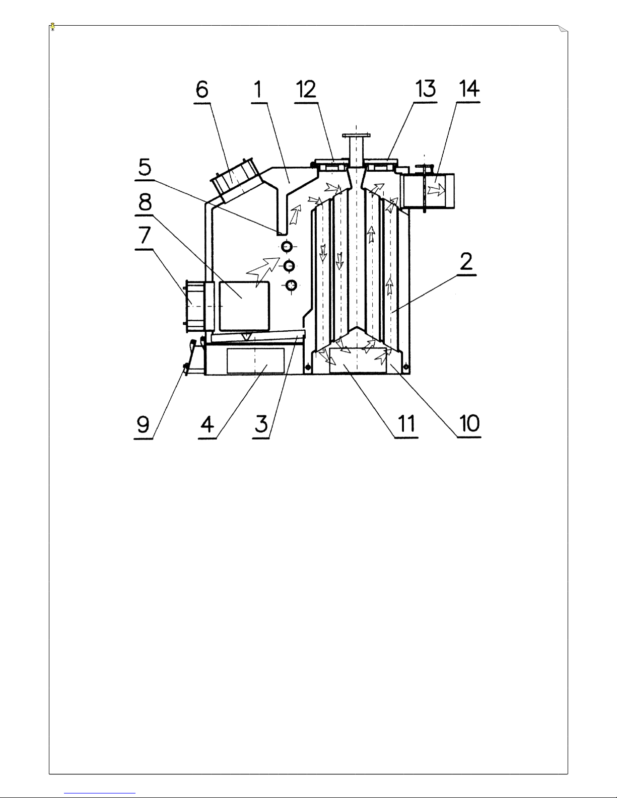
2.2. Technical description (fig.1.)
KWH is a low-temperature water boiler equipped with three-way (four-way)
exhaust gas circulation, fired with hot exhaust gas transferred to the
combustion chamber from a pre-furnace or with solid fuel. The structure is of
bent / welded type. Inside of boiler there are heated water chambers (1) built in
side walls and combustion tubes (2) forming two (three) exhaust gas drafts.
Pre-furnace contains flat water grid (3) made of steel profiles. The grid is also
included into boiler’s water circulation. Angled position of the grid in relation to
Page 4

HAMECH DTR KWH
4
boiler’s level ensures water circulation inside its structure, prevents excessive
furr deposit as well as allows gravitational water flow indispensable for proper
grid’s cooling. Below the grid there is an ash tray (4), above the grid there is a
vertical stopping wall (5). The furnace chamber is accessible through the
feeding door (6) and the grid door (7); access is also possible through side
walls openings which are simultaneously inlets for AZSD system (8). Boiler’s
structure allows wide adjustment of combustion air quantity. For this purpose
the boiler is fitted with ash door (9) together with an adjustable flap, which
enables adjustment of air coming under the boiler’s grid. The air can be also
supplied through tilted grid door (7) installed in boiler’s front wall. In the rear
part of the boiler below the row of combustion tubes there is a deposit chamber
(10) accessible through the door (11); access to combustion tubes from upper
side is possible through cleaning flaps (12) for the first and (13) for the second
row of combustion tubes. Exhaust gas outlet is realised through a flue (14).
The boiler can work with natural air draft generated by a funnel or with forced
draft generated by a fan.
2.3. Classification
Present operation manual is valid for boilers type KWH of thermal power: 55;
110; 180; 300; 600; 1000; 2000 kW;
2.4. Types of fuel
2.4.1. Basic fuels
The basic fuel for the KWH boilers coupled with an AZSD unit is comminuted
woodwaste of 30 mm granulation, 30 – 50% humidity and n.c.v. 13-8 MJ/kg
burnt in the pre-furnace.
2.4.2. Substitution fuel
Substitution fuels used in KWH boilers (when withot pre-furnace) are:
• big wood pieces
•
coal/lignite briquetts
•
coal/lignite
• mix coal + peat or coal + woodwaste
•
mix pea coal + culm from 1/2:3 to 3:1.
2.5. Boiler power for substitution fuel.
If necessary, the KWH boilers can be fired with substitution fuel
. Permanent
use of wet fuel and simultaneousy low temperature of exhaust gas –
below 160˚ C – leads to premature wear of the boiler.
The reason is
condensation of combustion products e.g. water, nitrogen oxides, sulphur
oxides etc., which create very agressive environment and cause corrosion of
steel boiler elements.
Page 5
HAMECH DTR KWH
5
When using these fuels the thermal efficiency drops, approximately
proportionally to the drop of n.c.v. (in relation to the basic fuel)
and
problems with boiler maintenance.
Negligence in frequent cleaning of the boiler may lead to problems with
removal of impurities from heated boiler’s surfaces, decrease of flow in exhaust
channels and drop of boiler’s efficiency.
2.6. Technical data.
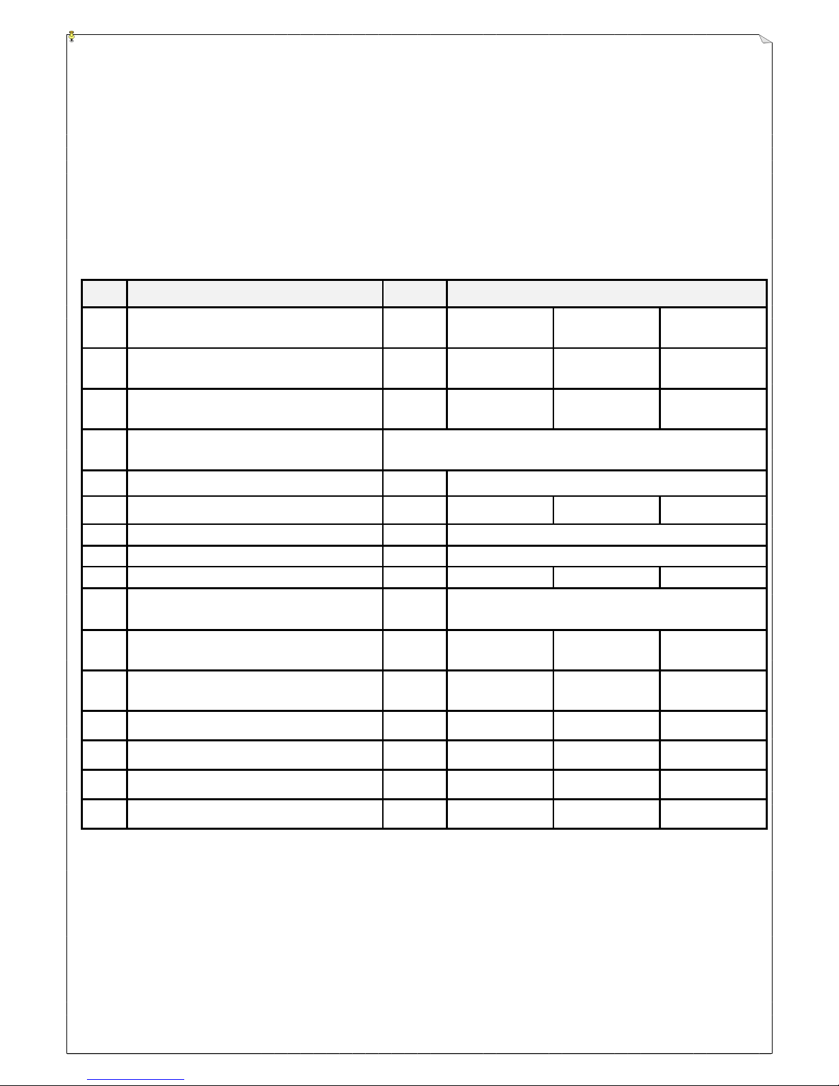
TABLE 1.
No.
Item
Unit
Thermal power
1 Rated thermal power kW
55 110 180
2
Adapted for co-operation with the
unit ♦
AZSD-50 AZSD-100 AZSD-180
3
Rated thermal power together
with AZSD
kW
60* 90** 190***
4 Basic fuel for AZSD
Comminuted wood of up to 30 mm granulation and
30-50% humidity
5 Thermal power adjustment range
% 30 - 100
6 Heated boiler surface m2 5,5 11,5 21
7 Admissible static pressure MPa 0,3
8 Max. temp. of outlet water ºC 95
9 Required draft behind the boiler Pa >23 >26 >29
10
Average exhaust gas temp. at
the flue
ºC 200
11
Basic fuel consumption at
nominal power of AZSD
kg/h 24,1* 40,57** 55***
12
Thermal efficiency at nominal
power when coupled with AZSD
%
≥77,7
≥78,7
≥78,7
13 Weight with insulation kg 600 1150 1750
14
Funnel height •
m 8 12 12
15
Funnel diameter •
mm 190 315 370
16 Water volume l 180 350 800
*- at n.c.v. 12 028 kJ/kg
** - at n.c.v. 9 535 kJ/kg
*** - at n.c.v. 15955 kJ/kg
♦ - connection dimensions – see appropriate drawings
• - with natural draft
Table 1 continued
Page 6
HAMECH DTR KWH
6
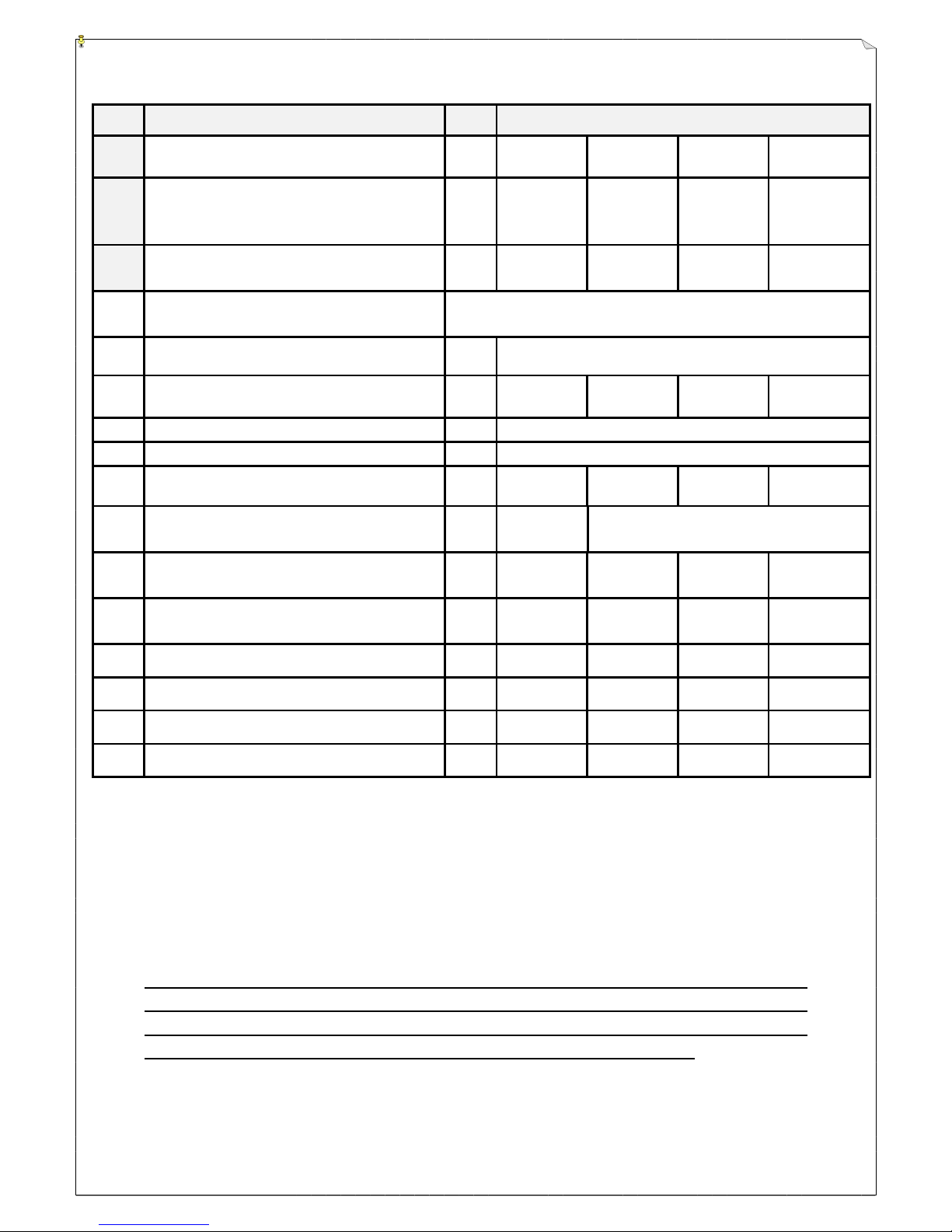
No. Item Unit
Thermal power
1 Rated thermal power kW
300 600 1000 2000
2
Adapted for co-operation with the
unit ♦
AZSD-
250
AZSD-
500#
AZSD-
1000##
2xAZSD-
1000
3
Rated thermal power together with
AZSD
kW
300* 550*** 1000* 2000****
4 Basic fuel for AZSD
Comminuted wood of up to 30 mm granulation
and 30-50% humidity
5 Thermal power adjustment range % 30 - 100
6 Heated boiler surface m2 25,0 49,0 78,0 174,0
7 Admissible static pressure MPa
0,3
8 Max. temp. of outlet water ºC 95
9 Required draft behind the boiler Pa >35 >40 >56 >65
10
Average exhaust gas temp. at the
flue
ºC 220 240
11
Basic fuel consumption at nominal
power of AZSD
kg/h
118,15∗ 156
∗∗∗
375,6∗ 783,7
∗∗∗∗
12
Thermal efficiency at nominal
power when coupled with AZSD
%
≥81,9
≥81,9
≥81,9
≥81,9
13 Weight with insulation kg 2150 3100 6250 12500
14
Funnel height •
m 15 18 22 29
15
Funnel diameter •
mm
490 620 800 1100
16 Water volume l 1400 2100 4300 7800
* - at n.c.v. 12 028 kJ/kg
*** - at n.c.v. 15955 kJ/kg
****- at n.c.v. 11484 kJ/kg
♦- connection dimensions – see appropriate drawings
# - it is possible to order a boiler adapted for 2xAZSD-250, see fig.7.
## - it is possible to order a boiler adapted for 2xAZSD-500, see fig.9.
•
- with natural draft
The nominal thermal power for the set boiler + AZSD is given for
optimum combustion conditions at defined fuel n.c.v. (fuel humidity).
When fuel of higher n.c.v. will be used, the thermal power will grow
proportionally in relation to the fuel the boiler was tested with
Page 7

HAMECH DTR KWH
7
2.7. Technical acceptance
The boiler is accepted by Manufacturer’s Quality Dept..
3.0. EQUIPMENT AND TOOLS INDISPENSABLE FOR OPERATION
3.1. Equipment for inspection & measurement
•
thermal pressure gauge 0 - 120ºC : 0,1 - 0,6 MPa 1
•
drain valves ¾” 2
• sealing for stub connectors 4
•
flanges 2
3.2. Equipment for maintenance & cleaning
•
brush 1
• ash rake 1
4.0. INSTALLATION (ASSEMBLY)
4.1. General
KWH boilers up to 1000 kW can be seated directly on boiler-room concrete
floor if its thickness is not less than 10 cm and if it is founded on a solid, nonsettling substrate. However, it is recommended to seat the boiler on a platform
to avoid corrosion of boiler’s bottom and walls as a result of water penetration
during emptying of the boiler. If boiler-room’s floor does not fulfil mentioned
requirements a foundation must be made.
For boilers from 1000 kW on must be made a concrete reinforced foundation of
250 mm thickness. After hardening of floor or foundation it is possible to
assembly the boiler.
Now:
•
in two-part boilers connect the combustion chamber with the exchanger;
seal connections.
•
connect the boiler to the central-heating system. The heating system must
comply with adequate standards and regulations.
•
fit the equipment i.e. drain valves and thermal pressure gauge.
• connect boiler’s flue to the funnel, seal connections.
•
The outlet duct (between flue and funnel) should have lift of not less than
1% and proper number of cleaning openings for removing of ash and soot.
Before connecting boiler and funnel check funnel’s dimensions acc. to the
Table 1.
•
If more than one boiler is connected to the funnel, funnel’s diameter should
be calculated as follows:
F- funnel’s cross-section cm
2
F x
Q
H
cm
=
25 73
2
, ( ) Q- sum of thermal powers of all boilers, kW
H- funnel height, m
Page 8

HAMECH DTR KWH
8
•
the value Q is calculated as the sum of thermal powers of all boilers
• optimum funnel height (calculated for sea level) should be taken from the
Table 1.
• for locations above sea level the value from the Table 1 should be
increased by 0,2 m for each 100 m above sea level.
•
Finally, check all connections for leakage and complete paint coat.
4.2. Additional information
Boiler should be located in the boiler-room so as it could be easily operated,
cleaned, assembled and disassembled. For this purpose distance between
boiler’s front wall and boiler-room wall for manually fed boilers should be by 0,5
m greater than boiler’s length but not less than 2,0 m.
Distance between boiler’s rear wall and any obstacle should allow for easy
opening of cleaning door. For its proper work the boiler must be placed at the
same height as foreseen in heating system design.
5.0. OPERATION MANUAL
5.1. Start-up
Firing-up of the boiler may be started after checking if the boiler and heating
system contains sufficient quantity of water i.e. if the expansion vessel contains
water – 100 mm above vessel’s bottom is quite enough (it may be done using
the signalling pipe). Check if all cleaning flaps are mounted and closed,
especially rear wall cleaning flap. Firing-up should proceed slowly. Flue gate
should be entirely open, sufficient quantity of air should be supplied through
the ash door. The boiled is fired-up using wood laid on the grid. After the wood
catches flame, add gradually fuel and fill the combustion chamber (i.e. start the
AZSD).
5.2. Operation (withot pre-furnace)
Boiler’s capacity adjustment (= outlet water temperature) should be done
through proper positioning of the ash door (9) flap, applied for supply of air
under the grid; quantity of air depends on boiler‘s thermal load. During initial
combustion phase carbon monoxide is burnt only partially, thus secondary air
should be supplied to the combustion chamber through the grid door (7)
installed in the upper part of the boiler. If the boiler is fired with thicker coal
(smaller billets or thick cobble) then it is recommended to fill the furnace
entirely and to control combustion speed with air quantity supplied under the
grid through the ash door flap.
Before each next fuel charge remove ash and slag from the grid; during this
operation the flue gate should be entirely open.
In the course of boiler operation observe industrial safety rules and check
indications of measurement gauges i.e. check if boiler’s working parameters
are not exceeded.
Page 9

HAMECH DTR KWH
9
5.3. Coupling with AZSD
The KWH boiler is adapted for coupling with a WOODWASTE COMBUSTION
UNIT AZSD.
The AZSD units are made within the range of thermal powers from 50 to 1000
kW and make possible automated burning of sawdust. Coupled with a boiler
forms excellend thermal system. The system can be set in various
configurations depending on required power and space of a boiler room.
Basic arrangement of the set is as follows:
the boiler of thermal power
matched to the power of the entire set and an AZSD pre-furnace coupled
on the right side of the boiler.
The combustion chamber has an opening adapted to the AZSD unit; the size
of openings depends on thermal power of an AZSD unit and made in such way
that having installed the pre-furnace just seal the slot with a graphite cord to
obtain tight connection and proper draft inside the furnace. The boiler coupled
with an AZSD can be fired also with solid fuel e.g. coal, woodwaste, wood-like
waste etc. without comminuting the fuel and disconnectiong the AZSD from the
boiler.
The boiler prepared for coupling with an AZSD can work alone as a solid fuel
fired device, because opening for the AZSD are covered with fire-resistant
door.
Technical conditions for operation of the AZSD unit are contained
in its operation manual.
There are two modes of boiler’s operation:
•
Continuous firing with smothering of fire during night hours.
•
Continuous firing.
The user decides which mode should be selected. If start-up follows longer
pause, first heat the funnel duct firing it with small, dry pieces of wood for 30
minutes. This rule is especially important
during firing-up of a newly
installed
boiler, when all smoke ducts are cold and damped; smoke comes
back through both charge and grid doors, also may appear the phenomenon of
“boiler’s sweating”
i.e. dark fluid flows from the boiler, often forming a stain
under it. This phenomenon recedes after one or two days.
Prior to combustion end stop fuel feeding. After the fuel is totally
burnt, open the charge and ash doors, also open the flue gate
entirely to cool down the boiler quickly. Remove ash and slag,
clean the combustion chamber walls, the grid, the combustion
tubes and the flue, finally close cut-off valves (if fitted).
5.4. Emergency stop
If the boiler does not work properly:
•
Stop feeding fuel.
•
Open the charge & ash doors and open the flue gate to extinguish glow
inside the boiler.
Page 10

HAMECH DTR KWH
10
•
Remove fuel, slag and ash from the boiler.
•
Close cut-off valves.
5.5. Water supply
Quality of water supplied to the boiler and heating system has major influence
on reliability and lifetime of the boiler. There are two reasons of boiler’s wear:
•
corrosion
•
furr deposits
Destruction (perforation) of walls as a result of corrosion appears rarely. Much
more often pipes and equipment are polluted – or even clogged – with furr;
valves are blocked. Especially dangerous are deposits at heat exchange
surfaces. Furr deposits form an insulation layer, which decreases heat transfer
to the heating media and may cause overheating of walls and consequently
boiler’s major damage.
Furr deposits decrease also water flow. Most suitable water for boilers &
heating systems is the rainwater.
Do not fill the boiler with water of unknown hardness.
It is permissible to supply water of maximum hardness of
4°n (1,44 mval/l)
;
additionally the water should be of alkaline reaction (i.e. pH higher than 7) and
free of salts and gases.
Tap water should be softened before use in the
boiler.
Water losses within properly designed and mounted heating system are
insignificant and require refilling very rarely.
6.0. INSPECTION AND MAINTENANCE MANUAL
Inspection and maintenance of measuring equipment & operation tools should
be done every 330 h of continuous work. During inspection it is recommended
to check leakage on welds, connections etc. and – if any – remove them or
seal connections.
6.1. Cleaning
The furnace & grid should be cleaned daily before firing-up the boiler. Partially
burnt fuel removed during cleaning should be thrown back into the furnace
after firing-up.
Boiler should be cleaned after every 200 h of continuous work with basic fuel.
Combustion tubes and their connections should be cleaned at least
every 10 days
, but this period depends on many factors e.g. fired fuel, funnel
draft, fuel humidity and may be shorter or longer than ten days.
Cleaning of combustion tubes is very important for the sake of heat exchange,
which is very intensive in this part of the boiler.
Cleaning of the boiler should be done first after the fuel is completely burnt out,
the glow is extinguished and the boiler is cold.
Operations during cleaning:
•
Open flaps (12) and (13), which close smoke walls of boiler’s exchanger.
Page 11

HAMECH DTR KWH
11
•
Clean combustion tubes and reversal chambers.
•
Clean the flue.
•
Check if the flue gate rotates freely.
After cleaning of combustion tubes clean also the ash chamber in boiler’s rear
part (exchanger) through the cleaning flap (11) located at boiler’s side.
6.2. Maintenance
After each heating season clean the boiler thoroughly.
Do not drain the water
for the summer season.
However, if the boiler-room is for any reason inactive during winter and there is
risk of frost,
drain the water.
After cleaning complete the paint coat on the
boiler.
7.0. REPAIR AND OVERHAUL
Minor defects should be removed during current repairs. Periodical overhauls
are made once a year, when the boiler is out of use. For inspection and for
evaluation of the range of repair clean the boiler thoroughly. Overhaul consists
usually in replacement of seals, door screens etc., rarely in replacement of
water grid, which is worn due to furr deposit. After overhaul check tightness of
boiler & heating system. After replacement of side walls and grid or after repair
of breaks and leakage carry out the 0,4 MPa pressure test.
8.0. INDUSTRIAL SAFETY
Operation of the boiler is safe only if the boiler is installed and operated
according to adequate standards and present manual. Especially following
rules should be observed:
•
Fire up the boiler only if the boiler & heating system are filled with sufficient
quantity of water and if inlet and outlet valves are open.
•
To avoid intoxication with carbon monoxide the blow duct in the upper part
should be always opened a little.
•
Observe fire protection rules – keep boiler’s surroundings clean, do not
store inflammable materials near the boiler.
•
Connection to the funnel should be made very carefully, seal all connec-
tions with chamotte clay or graphite cord.
•
If temperatures are low, the heating system is cold and if there is a risk that
the system is frozen behind the boiler do not fire up the boiler before
checking that there is circulation of water in the system.
•
If there is no water in the boiler or in the heating system and the boiler is
filled with glowing fuel
IT IS PROHIBITED!:
•
to fill the system with cold water – risk of boiler’s explosion
•
to extinguish the furnace with water – risk of boiler’s break and
carbon monoxide formation.
Page 12

HAMECH DTR KWH
12
•
in this case remove fuel from the furnace, take it out from the boiler-
room and extinguish. Fill the boiler & heating system with water after
repair and cooling down.
Water temperature and pressure must not exceed permissible values.
Only trained and qualified personnel should operate the boiler.
8.1. Description and evaluation of residual risk
8.1.1. Description of residual risk
Although the MACHINERY WORKS „HAMECH” in Hajnówka take responsibility for design and structure of the device with regard to its safety, certain
risk level during operation of the KWH boiler cannot be avoided.
Usually, the residual risk results from improper behavior of an operator.
The greatest risk appears during execution of following prohibited actions:
- presence of unauthorized persons in the vicinity of the device during its
operation,
- filling of warm boiler with cold water,
- extinguishing of the furnace with water
- operation at exceeded values of temperature and pressure
- cleaning of ash chamber without protection clothes
When presenting the residual risk the KWH boiler is treated as a device, which
until the moment of its start-up is designed and manufactured according to the
state-of-art.
8.1.2. Evaluation of the residual risk
If following recommendations are observed:
- careful acquaintance with the manual
- execution of all repairs of the electric system by an authorized
electrician,
- inspection of the earthing system after repair of the electric system prior
to operation,
- no unauthorized persons in the vicinity of operating machine,
- operation, maintenance and repair of the device only by properly trained
personnel, who are acquainted with the manual,
- use of personal protection means: tight clothing, protection gloves, face
protection etc.
- observance of recommendations concerning operation and maintenance
of the boiler contained in the manual
the residual risk can be eliminated during operation of the KWH boiler without
risk to people and environment.
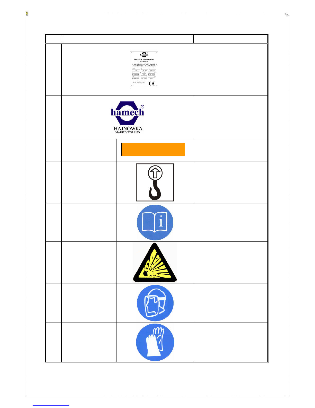
8.2. List of warning and information signs for the KWH boiler.
The signs are permanently put onto the housing of the device; their location is
shown on figs.1-9. In the case of destruction / damage new signs can be
delivered by the ZM HAMECH; together with the order give the description of
the sign as in the table below:
Page 13
HAMECH DTR KWH
13
No.
Sign Description
1.
Type plate
2.
Plate HAMECH
3.
Black letters,
orange
background
Boiler thermal power
4.
Black letters,
yellow
background
Lift here.
5.
White sign,
blue background
Prior to operation read
the manual.
6.
Black symbols,
yellow
background
Plate „Risk of explosion”
7.
White sign,
blue background
Face protection
8.
White sign,
blue background
Hand protection
KWH-600
Page 14

HAMECH DTR KWH
14
9.0. TRANSPORT
Gthe KWH boilers are supplied completely assembled; from the size 180 on –
in two parts.
The boiler should be transported in vertical position and protected from
mechanical damage, which may cause break of welds or destruction of thermal
insulation. The boiler is fitted with lifting eyes. Boilers must not be dropped
down from a truck, turned over, but should be handled wity care. It is prohibited
to place boilers one on another during transport and storage. The boiler should
be stored under roof and protected from corrosion.
10.0. FAILURES
Boiler failures result usually in decrease of its thermal efficiency.
POSSIBLE REASONS:
•
Poor fuel quality
low heating value, great content of ash and fine culm. Low quality fuel
should be used only when boiler’s high thermal efficiency is not requested.
•
Insufficient funnel draft
Remove leakage of funnel, doors, flue etc. Check funnel’s height acc. to the
Table 1, check funnel duct
•
Boiler and convection ducts polluted
Clean ducts inside boiler and flue
•
No air supply under grid
To much ash in the furnace, to small opening of ash door
•
No air supply to the boiler-room
Enable fresh air flow through a window or a ventilation duct
11.0. FUEL STORAGE / MINIMUM FUEL STOCK
Fuel stocks may be prepared as:
•
bank-type, with or without roof
•
tank-type
•
chamber-type, as a part of building’s space
Approximated average daily fuel consumption during heating season can be
calculated as follows:
D
Q
S xW
z
zn
P o
=
3456
D
z
average daily consumption Mg
Q
zn
total rated power of all installed boilers kW
S
p
average thermal efficiency of boilers %
W
o
n.c.v. of stored fuel kJ/kg
Page 15
HAMECH DTR KWH
15
FIG. 1 Water boiler - structure
Page 16
HAMECH DTR KWH
16
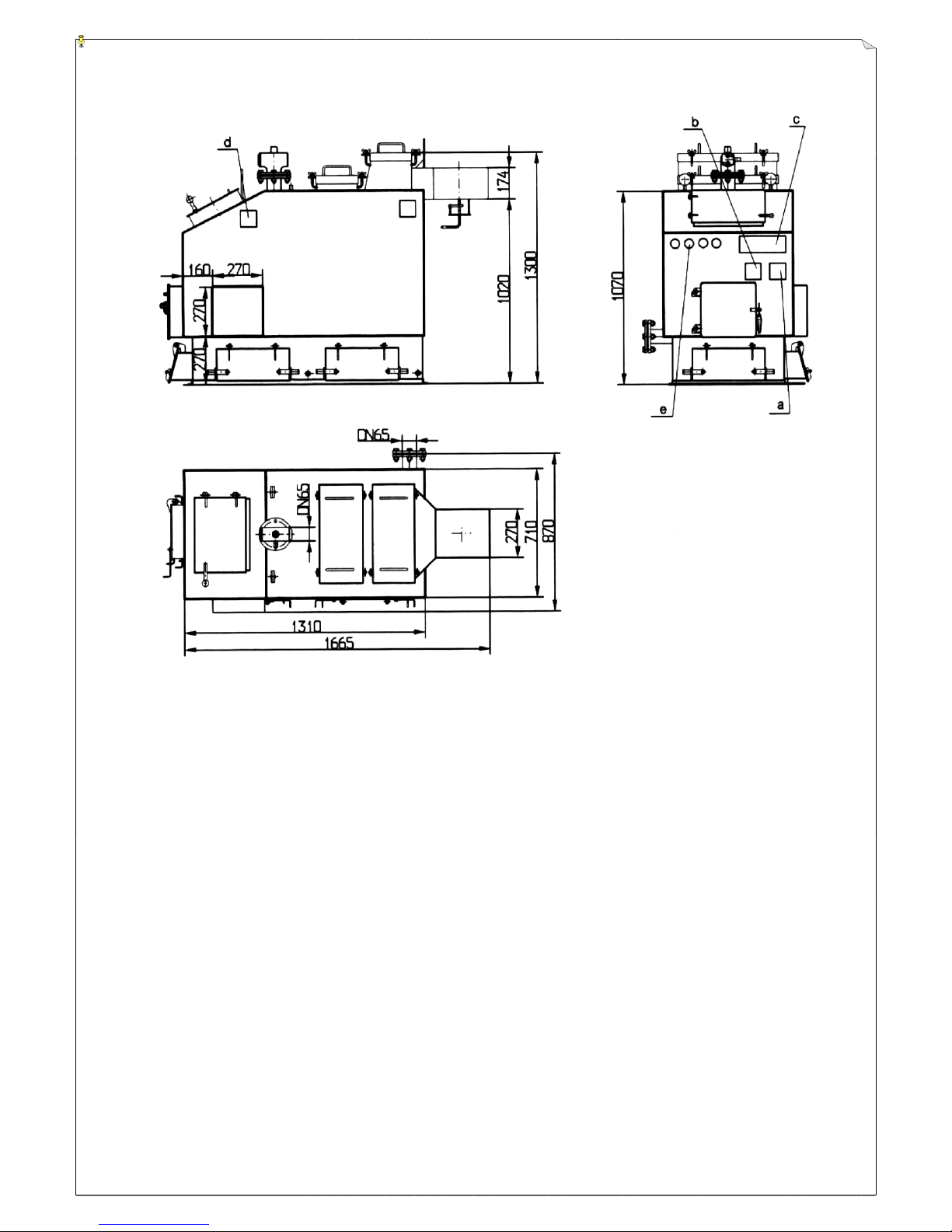
FIG. 2 Water boiler KWH – 55 / dimensions /
(location of warning & information stickers is also shown)
a-sign No. 1, b-sign No.2, c-sign No.3,d-sign No.4, e-sign No.5-8.
Description of signs is given on p. 13-14
Page 17
HAMECH DTR KWH
17
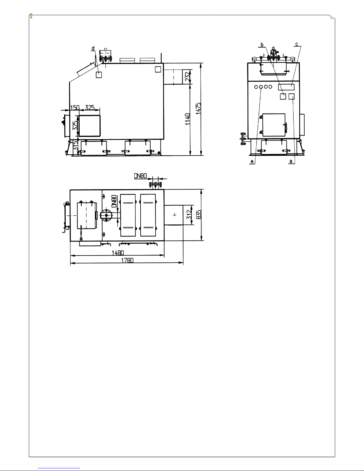
FIG. 3 Water boiler KWH – 110 / dimensions /
(location of warning & information stickers is also shown)
a-sign No. 1, b-sign No.2, c-sign No.3,d-sign No.4, e-sign No.5-8.
Description of signs is given on p. 13-14
Page 18
HAMECH DTR KWH
18
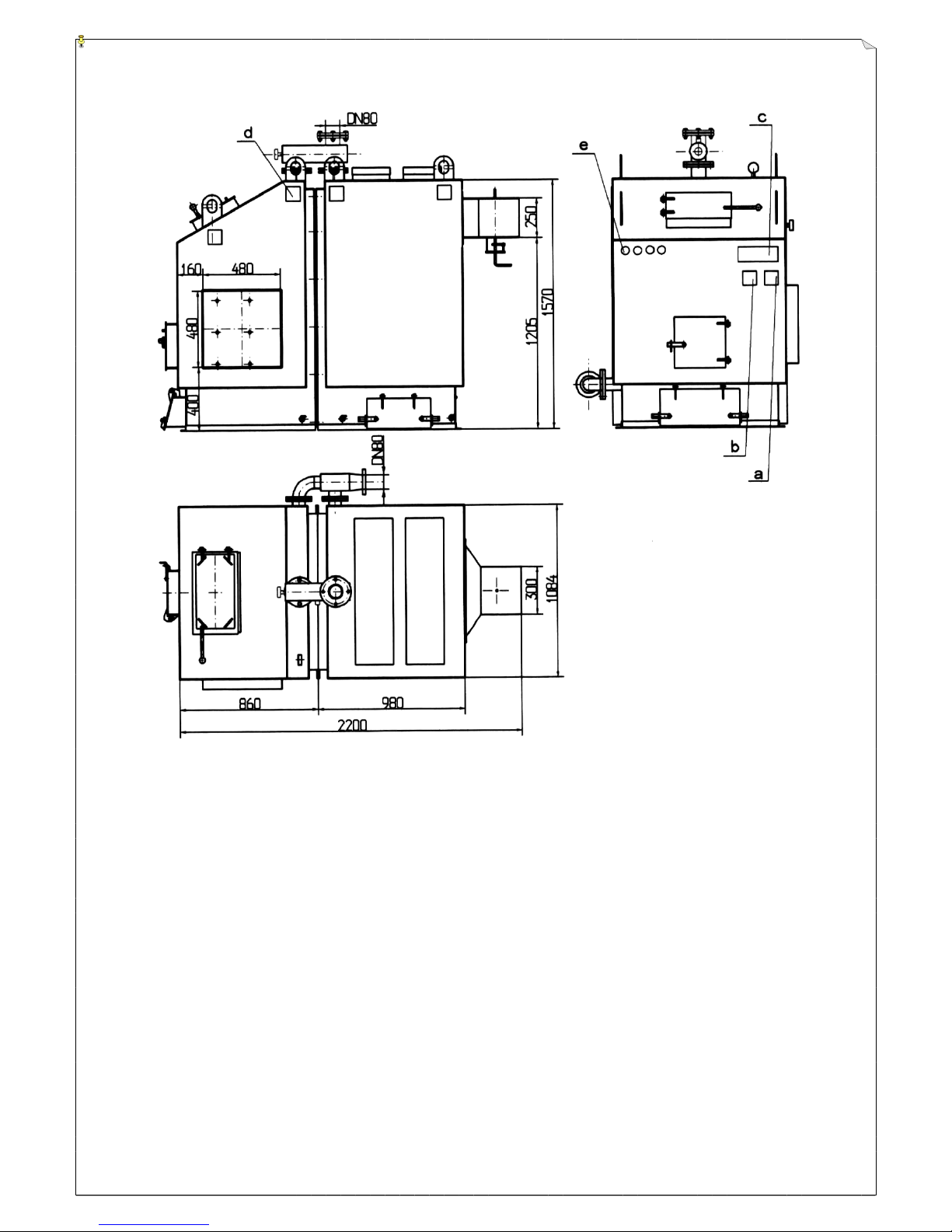
FIG. 4 Water boiler KWH – 180 / dimensions /
(location of warning & information stickers is also shown)
a-sign No. 1, b-sign No.2, c-sign No.3,d-sign No.4, e-sign No.5-8.
Description of signs is given on p. 13-14
Page 19
HAMECH DTR KWH
19
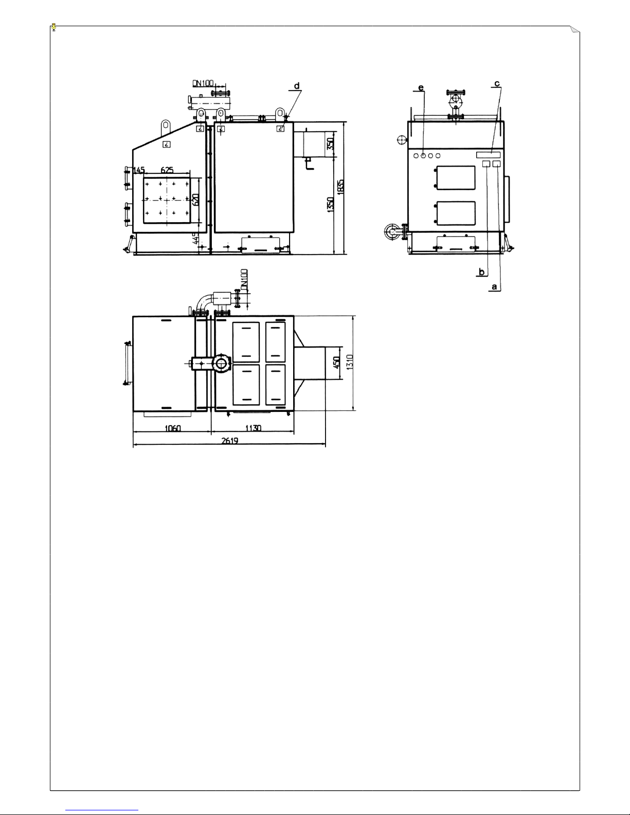
FIG. 5 Water boiler KWH – 300 / dimensions /
(location of warning & information stickers is also shown)
a-sign No. 1, b-sign No.2, c-sign No.3,d-sign No.4, e-sign No.5-8.
Description of signs is given on p. 13-14
Page 20
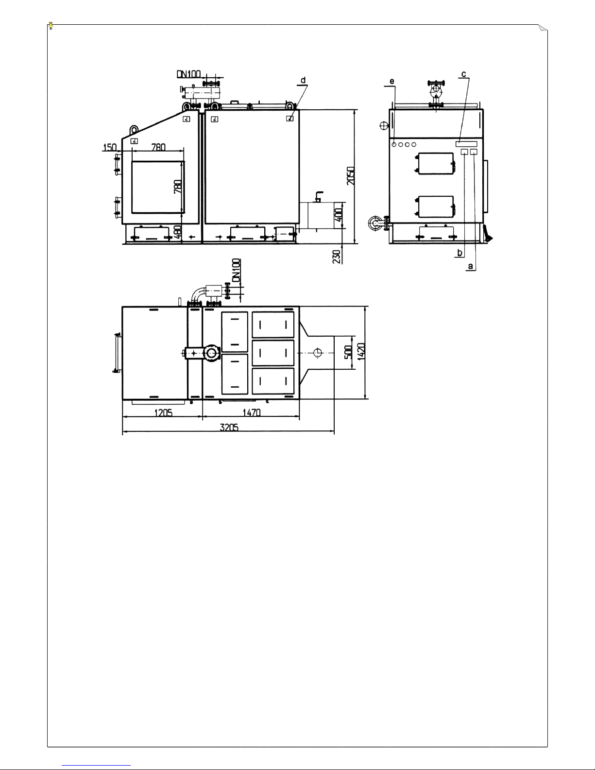
HAMECH DTR KWH
20
FIG. 6 Water boiler KWH – 600 / dimensions /
(location of warning & information stickers is also shown)
a-sign No. 1, b-sign No.2, c-sign No.3,d-sign No.4, e-sign No.5-8.
Description of signs is given on p. 13-14
Page 21
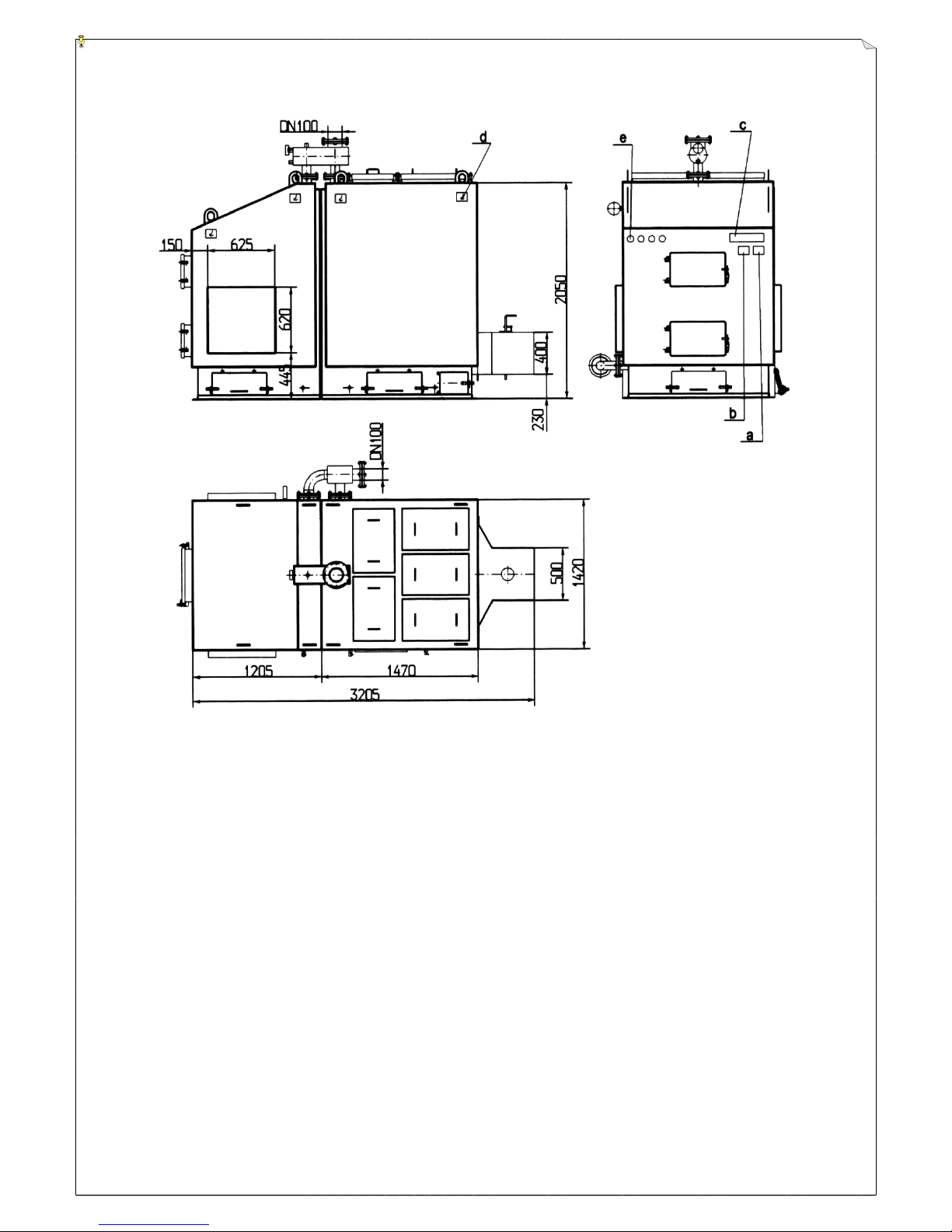
HAMECH DTR KWH
21
FIG. 7 Water boiler KWH – 600/2xAZSD-250/ ( dimensions )
(location of warning & information stickers is also shown)
a-sign No. 1, b-sign No.2, c-sign No.3,d-sign No.4, e-sign No.5-8.
Description of signs is given on p. 13-14
Page 22
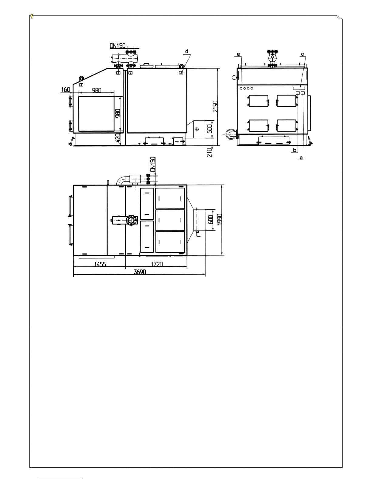
HAMECH DTR KWH
22
FIG. 8 Water boiler KWH – 1000 / dimensions /
(location of warning & information stickers is also shown)
a-sign No. 1, b-sign No.2, c-sign No.3,d-sign No.4, e-sign No.5-8.
Description of signs is given on p. 13-14
Page 23
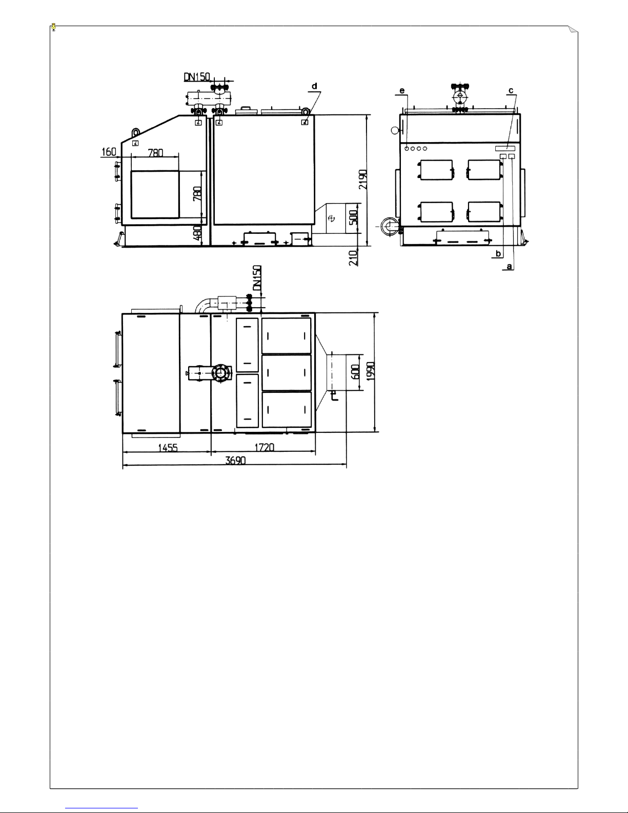
HAMECH DTR KWH
23
FIG. 9 Water boiler KWH – 1000/2xAZSD-500/ ( dimensions )
(location of warning & information stickers is also shown)
a-sign No. 1, b-sign No.2, c-sign No.3,d-sign No.4, e-sign No.5-8.
Description of signs is given on p. 13-14
Page 24
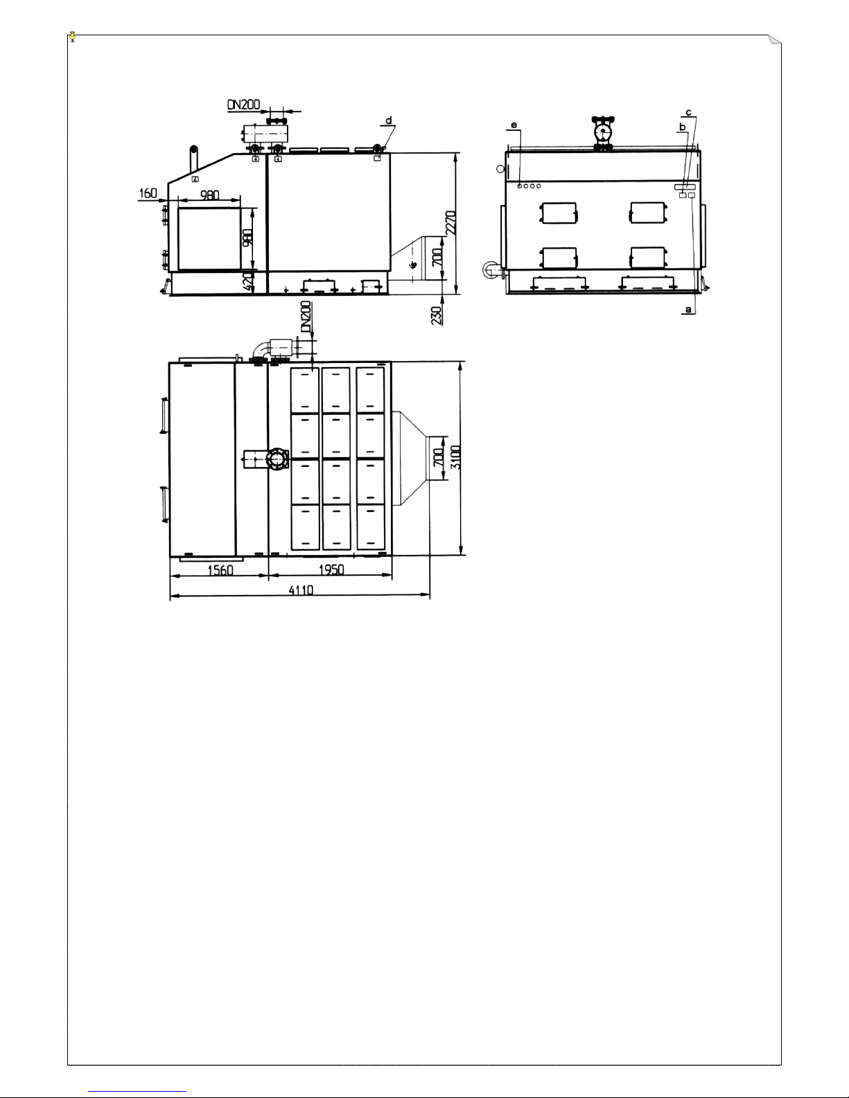
HAMECH DTR KWH
24
FIG. 10 Water boiler KWH – 2000 / dimensions /
(location of warning & information stickers is also shown)
a-sign No. 1, b-sign No.2, c-sign No.3,d-sign No.4, e-sign No.5-8.
Description of signs is given on p. 13-14
Page 25

HAMECH DTR KWH
25
CERTIFICATE
For manufacturing and testing
of the low-temperature steel water boiler type
: KWH
1. Manufacturer:
Machinery Works HAMECH
17-200 Hajnówka
Ul.Armii Krajowej 3
2. Boiler serial ..................................................................................
3. Manufacturing year .....................................................................
4. Max. water pressure inside the boiler ...........................................MPa
5. Max. water temperature ..............................……..........................95ºC
6. Wielkość kotła ...............................................................................kW
WE CERTIFY
that the boiler has undergone structure inspection and tightness test with
pressure........... MPa at Manufacturer’s site and has been admitted for
operation with pressure ............ MPa.
…………….......
Page 26

HAMECH DTR KWH
26
WARRANTY CARD No. ...................
Product :
Central-heating water boiler
Type:
KWH
Serial:...................................
Manufacturing date: .....................................
Dispatch date: ...............................
Sale date: .............................
...........................................
Signature & stamp Quality Dept
..................................................................
point of sale – signature & stamp
COMPLAINT FORM
Mr (Mrs)...........................................................................................................................
Address...........................................................................................................................
.............................................................................................…........................................
Warranty card No. ...........................................................………....................................
Product type & serial ....................................................…….........................................
Purchase date ........................................…….........................………..................
Start-up date ...........................................…......................……………..........................
Short description of the defect.........................................................................................
....................................................................…..................................................................
..........................................................................................................................................
.........................................................................................................................................
..........................................................................................................................................
.....................................................................................................................................
Page 27

HAMECH DTR KWH
27
WARRANTY CONDITIONS
1. The manufacturer is obliged to repair for his own cost any physical defect revealed during
warranty period.
2. The warranty period lasts 12 months from the sale date.
3. The manufacturer ensures the warranty service term of 14 days from the complaint date.
4. The warranty period will be lengthened by the time of repair, counting from the complaint
date to the date of the repair’s finish, if the defect has made the device out of order.
5. The manufacturer takes no responsibility resulted from the warranty in following cases:
a) mechanical damages rsulting from improper transport or storage,
b) improper assembling, maintenance and operation (not conformable with the
operation manual),
c) repairs conducted by unauthorized personnel without manufacturer’s
agreement,
d) introduction of structure changes without written manufacturer’s agreement,
e) if the buyer has not informed the manufacturer in the 14-days term, that the
device is not complete.
f)
Firing with woodwaste poluted with chemical substances causing corrosion of
boiler’s interior (eg. sawdust from a tannery).
6. All adjustment and maintenance works, as well as replacement of parts, which should be
performed by the user as described in the manual, are not warranty repairs.
7. The warranty card is valid if contains dealer’s sign, stamp and date of sale.
8. A copy of the warranty card can be issued if the buyer submits any document of purchase.
9. If the complaint was groundless all costs bears the buyer.
10. Complaint should be submitted in written according to enclosed complaint form. In
urgency the complaint may be submitted by phone. User should record the time of the talk
and the name of the person, which accepted the complaint. The phone complaint should be
confirmed in written a.s.a.p.
11. Any contention not regulated in present warranty card is subject of The Civil Code
regulations, Art. 577-581.
CAUTION!:
-
Be acquainted with the operation manual before operation,
-
In the case of lack of the warranty card user has no right to repairs for
manufacturer’s cost.
Page 28

HAMECH DTR KWH
28
ZAKŁADY MASZYNOWE „ HAMECH” P. P.
17-200 HAJNÓWKA, ul. Armii Krajowej 3
tel.085 682 2021
fax085 682 2207
CONFORMITY DECLARATION
No. 1/KWH/04
Product: WATER BOILER C.O
Type: KWH-55; 110; 180; 300; 600; 1000; 2000
Serial.................... Manufacturing year...................
Thereby we responsively declare that the product being the subject of
present declaration is conformable with following standards and other
normative regulations:
•
• Directive 98/37/EU /Decree of the Ministry of Economy, Labor and
Social Policy dated on 10.04.2003r. for basic requirements for
machinery and safety elements (Dz.U.Nr 91, pos. 858 dated on
23.05.2003r.)
including the standard:
-
PN-EN-292-2:2000 – Machinery. Safety. Basic terms, general
design principles. Principles and technical requirements.
and other standards:
-
PN-EN 303-5 z 04.2002 part.5 Heating boilers for solid fuel with
manual & automated fuel feeding and rated for power below 300
kW – Terminology, requirements, tests and marking
The present conformity declaration becomes void if the KWH boiler
will be modified or rebuilt without our consent.
Hajnówka, 21.06.2004.
........................................
 Loading...