


Follow the safety precautions in Chapter 1 in order to avoid personal injury and
reading this manual, store it in a location where you can refer to it at any time.
ORCA-Flash4.0 V3
Digital CMOS Camera
C13440-20CU / C13440-20CU01
Instruction manual
Thank you for your purchase
•
damage to property when using this system. The manual describes the correct
handling method of t he sy ste m and pr ov i des i nstructions that should be followed
to avoid accidents. Read this manual carefully before using this system. After
Ver.1.3
April 2017
HAMAMATSU PHOTONICS K.K.
A3410301-03

~ Blank page ~

C13440-20CU / C13440-20CU01 Instruction manual_Ver.1.3
Improper handling of the camera without observing these warnings could
lead to serious injury to the user and even death.
Improper handling of the camera without observing these cautions could lead
to personal injury to the user or damage to propert y.
is forbidden. Read and follow the instructions
Note
This symbol indicates a note to help you get the best performance from the camera. Read
these notes might impair the performance of the camera.
1. SAFETY PRECAUTIONS
1-1 SYMBOLS
The symbols shown belo w ar e used f or t his camera.
Direct current
Alternating current
1-2 CLASSIFICATION OF WARNINGS
We have classified the war ning s symbols that appear in this ins t r uct ion manual and on the camera
as follows for your convenience. Make sure that you fully understand them and follow the
instructions they contain.
This symbol indicates a cautionary item that should be followed when handling the
camera. Read the contents carefully to ensure correct and safe use.
This symbol indicates an action that
carefully.
This symbol indicates a compulsory action or instruction. Read and follow the instructions
carefully.
the contents of the note carefully to ensure correct and safe use. Failure to observe one of
3

C13440-20CU / C13440-20CU01 Instruction manual_Ver.1.3
Power supply
voltage can damage the camera and lead to fire or electric shock.
Cables
damage the cables and lead to fire or electric shock.
Do not attempt to dismantle or modify the camera
manual.
Do not allow foreign objects
These can damage the camera and lead to fire or electric shock.
In the event of an anomaly
your local distributor. Do not attempt to repair the camera yourself.
Use the camera with th e indicated voltage on the rating sticker. Using a different
Do not to place heavy objects on cables or bend them exce ssively. Doing so ca n
Power supply cord
Use the accessory power supply cord when using this camera.
AC adapter
Use the accessory AC adapter when this using this camera.
Do not touch the plug with wet hands. Doing so can lead to electric shock.
Doing so can also lead to damage and even injury, as some internal components
become very hot or high voltage. Do not touch parts that are not indicated in this
Such as combustible substances, metal objects or water to get inside the camera.
such as the image suddenly disappearing or the occurrence of a strange noise, a
strange smell or smoke coming from the system, immediately turn off the power
switch and unplug the power supply cord and contact a Hamamatsu subsidi ary or
4

C13440-20CU / C13440-20CU01 Instruction manual_Ver.1.3
AC adapter
from the outlet to avoid causing elec tric shock or fire.
Connecting and disconnecting cables
disconnecting cables.
Mounting the camera
surface of the base plate. Screwing it in further can impair normal operation.
Lenses (C13440-20CU)
can have a thread of 7 mm or more.)
Shipping precautions
packaging material or something similar.
Strong impact
damage the camera.
Operating environment
This camera is designed and tested for use in an industrial environment. If this
This camera must not be used in residential areas.
Disposal
disposing of the camera, take appropriate measures in compliance with
applicable regulations regarding waste disposal and correctly dispose of it
province to ensure the camera is disposed of legally and correctly.
When unplugging the power supply cord, do not pull on the cord. Remove the plug
When unplugging the power supply cord, do not pull on the cord, but remove the
plug from the camera to avoid breakdown of the AC adapter
Always turn off the power supply of the peripheral device before connecting and
When mounting the camera to a tripod or other fix ture , use the optional base plate.
Be careful that the mounting screw does not enter more than 8 mm from the
or the camera.
Be careful not to screw the lens more than 7 mm into the C-mount of the camera.
Doing so can scratch the protective glass. (Some wide-angle lenses in particul ar
When transporting the camera by truck, ship, airplane, etc., wrap it securely in
Do not subject the camera to strong shocks (such as dropping it). Doing so can
camera is used in residential areas, EMI (electro-magnetic interference) may occur.
When
yourself, or entru st disposal to a lic ensed industrial w aste disposal comp any.In
any case, be sure to comply with the regulations in your country, state, region or
5
C13440-20CU / C13440-20CU01 Instruction manual_Ver.1.3
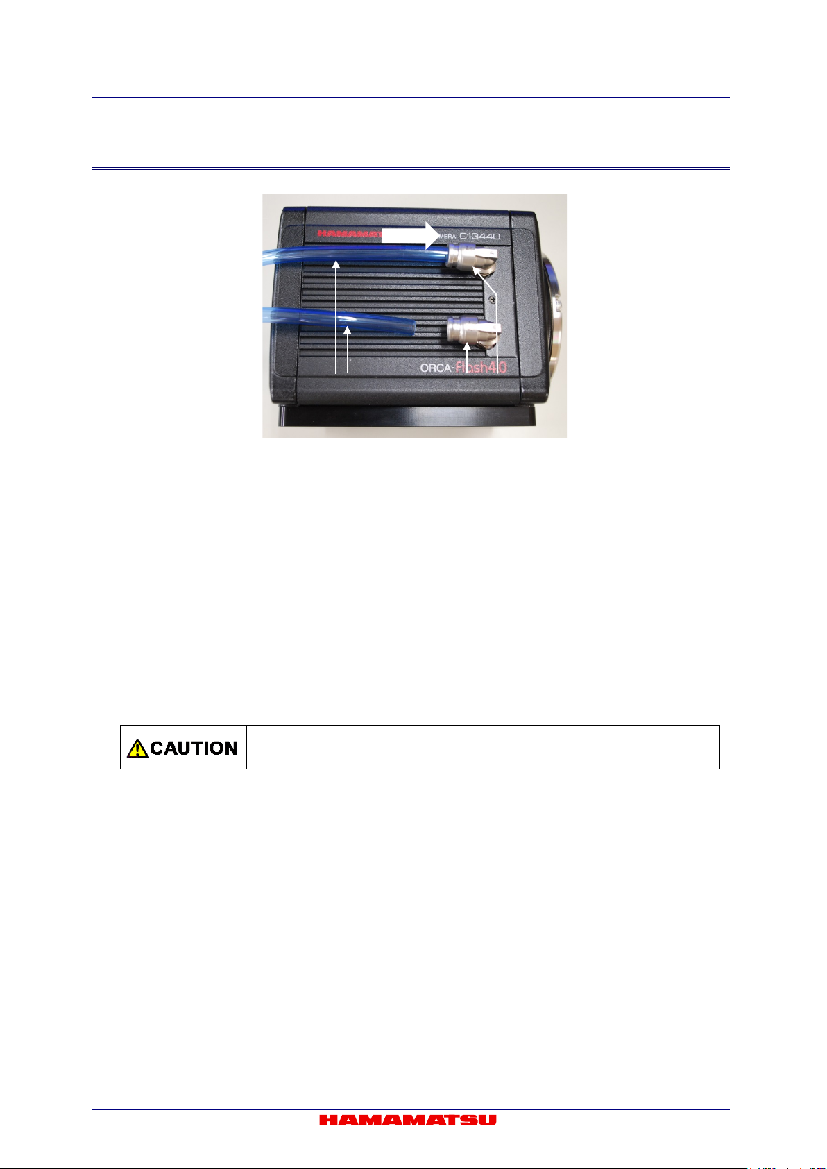
Using water cooling
water hoses.
Cooling water
Hamamatsu subsidiary or your local distributor.
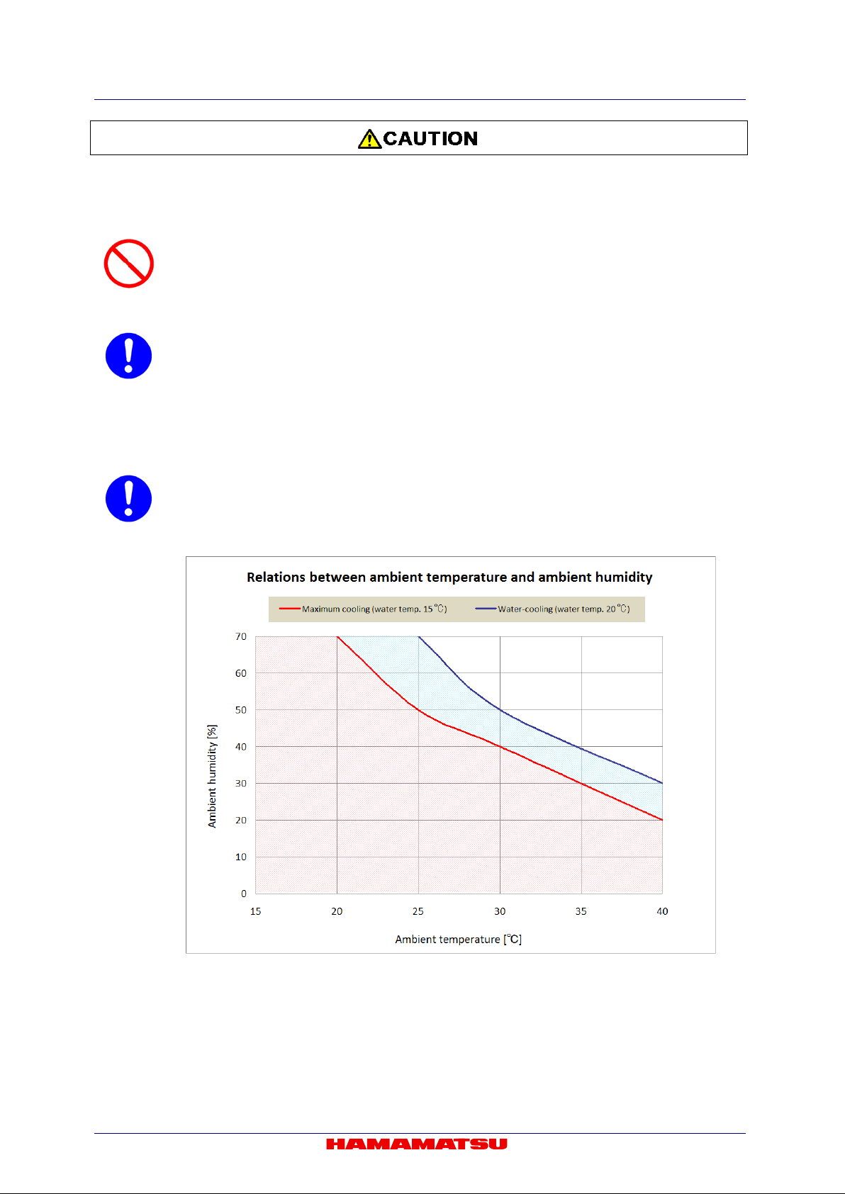
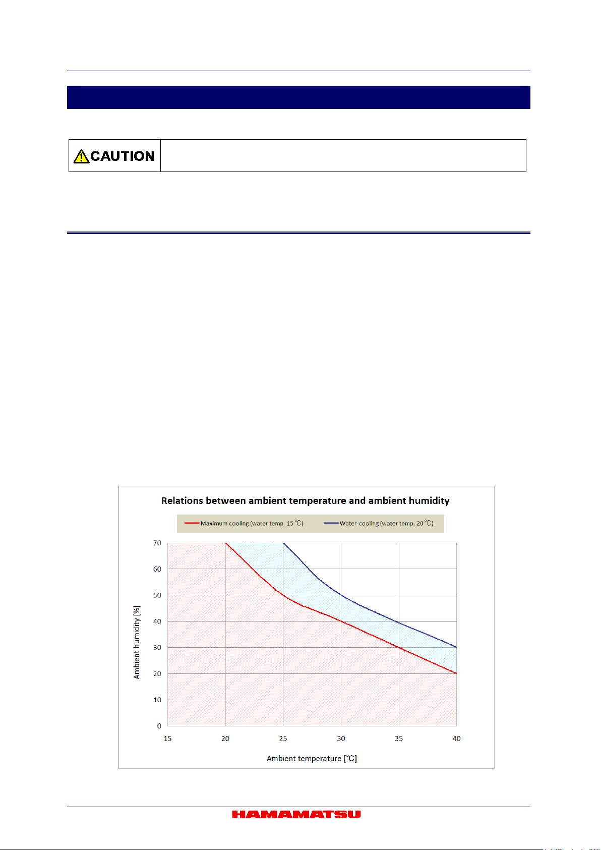
Condensation
condensation will not take place referring to the following graph.
Be careful water does not splash on the camera. Cut off the power supply of the
circulating water cooler and the camera when you remove and install the cooling
It is recommended to use soft water (except pure water) for cooling water. Follow
instruction manual which is attached to your circulating water cooler for an
appropriate temperature range of cooling water. If you plan on using water other
than soft water as recommended for example antifreeze etc, please refer to
description of cooling water which is written in 12. “MAINTENANCE
” o r contact a
At the Water-cooling, if ambient temperature and ambient humidity become high,
condensation will t ake place eas ily. Use the camera un der the env ironment w here
6

C13440-20CU / C13440-20CU01 Instruction manual_Ver.1.3
Camera: C13440-20CU or C13440-20CU01
1
AC adapter
1
Power supply cord for AC adapter
1
Lens mount cap (attached to the camera)
1
C13440-20CU Before Use (Booklet)
1
C13440-20CU Instruction manual (CD-ROM)
1
QC sheet
1
[Option]
Cooling water hose (2 hoses)
A10788-04
SMA-BNC cable
A12106-05
SMA-SMA cable
A12107-05
Camera Link interface board
M9982-29
Camera Link interface cable
A14038-04
USB 3.0 interface board
M9982-25
USB 3.0 interface cable
A12467-03
Adjustable pole for C11440-22CU
A11185-01
Fixing bracket for C11440-22CU cable
A13261-01
Note
Note
2. CHECK THE CONTE NT S OF PACKAGE
When opening the package, check that t he f ol low i ng items are included before us e.
If the contents are incorrect, insufficient or damaged in any way, contact a Hamamatsu subsidiary
or your local distributor before at tempting to operate the cam er a.
• Handle the circulating water cooler and the cooling water according to the instruction manual
of the circulating water cooler.
• The cable listed in option is highly recommended for use with the camera. The camera
system may not confirm to CE marking regulation if other type of cable is used with.
• If you use the above options, please refer to the each installation manual.
7

C13440-20CU / C13440-20CU01 Instruction manual_Ver.1.3
Places where the temperature is not the operating temperature indicat ed in the spe cifi cat ion s
• Places where there is a lot of dust
How to place the camera (when the camera is placed on a table)
other material, or in any way allow the camera’s ventilation ports to become
closed environment, ensure
up when setting up the camera.
3. INSTALLATION
Avoid using or storing this camera in the following places
•
• Places where the temperature is not the storage temperature indicated in the specifications
• Places where the temperature varies greatly
• In direct sunlight or near a heater
• Places where the humidity levels are not the operating humidity levels indicated in the
specifications and where the camera may be exposed to liquid
• Places where the humidity levels are not the storage humidity levels indicated in the
specifications and where the camera may be exposed to liquid
• Close to a strong source of magnetism or ratio waves
• Places where there are vibrations
• Places where the camera may come into contact with corrosive gases (such as chlorine or
fluorine)
Place the camera with water connectors on the side.
Do not place the camera with the vent opening, water c onnections or re ar panel on
the bottom. (Do not block ventilation openings.)
Do not allow the ventilation ports to become blocked.
To prevent the camera from overheating, do not wrap the camera in cloth or any
blocked. If the camera is being operated in an
clearance of at least 10 cm from both the intake and exhaust vents when setting
Weight of the camera
Be careful not to drop the camera when moving it as it is approx. 2.2 kg.
8

C13440-20CU / C13440-20CU01 Instruction manual_Ver.1.3
CCoonntteennttss
1. SAFETY PRECAUTIONS ................................................................................... 3
1-1 SYMBOLS ........................................................................................................................... 3
1-2 CLASSIFICATION OF WARNINGS ................................................................................... 3
2. CHECK THE CONTENTS OF PACKAGE .......................................................... 7
3. INSTALLATION .................................................................................................. 8
4. OVERVIEW ....................................................................................................... 11
5. FEATURES ....................................................................................................... 12
6. NAME AND FUNCTION O F PARTS ................................................................ 15
7. CONNECTION .................................................................................................. 18
8. WATER COOLING ........................................................................................... 20
8-1 CAUTIONS ........................................................................................................................ 20
8-2 CONNECTION OF WATER COOLING HOSES ............................................................... 22
8-3 DISCONNECTION OF WATER COOLING HOSES ......................................................... 23
9. OPERATIONS .................................................................................................. 24
9-1 OPERATING PRECAUTIONS .......................................................................................... 24
9-2 PREPARATING FOR IMAGING ....................................................................................... 25
9-3 IMAGING ........................................................................................................................... 25
9-4 END OF IMAGING ............................................................................................................ 25
9-5 STARTUP DCAM CONFIGURATOR ............................................................................... 26
10. DESCRIPTION OF CMOS IMAGE SENSOR ................................................... 28
10-1 THEORY OF CMOS IMAGE SENSOR ............................................................................. 28
10-2 READOUT METHOD OF CMOS IMAGE SENSOR ......................................................... 29
10-3 PRECAUTION WHEN USING CMOS IMAGE SENSOR ................................................. 29
11. DESCRIP T ION OF VARIOUS FUNCTIONS .................................................... 30
11-1 NORMAL AREA MODE .................................................................................................... 30
11-2 LIGHTSHEET READOUT MODE ..................................................................................... 49
11-3 W-VIEW MODE ................................................................................................................. 56
11-4 DUAL LIGHTSHEET READOUT MODE .......................................................................... 68
11-5 REAL-TIME DEFECT PIXEL CORRECTION ................................................................... 74
11-6 DATA REDUCTION FUNCTIONS .................................................................................... 75
11-7 MASTER PULSE............................................................................................................... 77
12. MAINTENANCE ................................................................................................ 79
12-1 CARE ................................................................................................................................. 79
12-2 INFORMATION ON COOLING WATER FOR THE CIRCULATING WATER COOLER . 80
13. TROUBLESHOOTING ...................................................................................... 81
13-1 IMAGE IS NOT TRANSFERRED ...................................................................................... 81
13-2 ALTHOUGH IMAGES ARE TRANSFFERED .................................................................. 81
9

C13440-20CU / C13440-20CU01 Instruction manual_Ver.1.3
14. SPECIFICATIONS ............................................................................................ 82
14-1 CAMERA SPECIFICATIONS ............................................................................................ 82
14-2 CONDENSATION.............................................................................................................. 85
14-3 SPECTRAL RESPONSE CHARACTERISTICS (TYP.) ................................................... 86
14-4 INTERFACE SPECIFIC ATIONS ....................................................................................... 87
14-5 OUTPUT TIMING SPECIFICATIONS ............................................................................... 89
15. DIMENSIONAL OUTLINES .............................................................................. 93
15-1 C13440-20CU .................................................................................................................... 93
15-2 C13440-20CU01 ................................................................................................................ 94
16. WARRANTY ..................................................................................................... 95
16-1 BASIC WARRANTY ......................................................................................................... 95
16-2 REPAIRS ........................................................................................................................... 95
17. CONTACT INFORMATION .............................................................................. 96
10

C13440-20CU / C13440-20CU01 Instruction manual_Ver.1.3
4. OVERVIEW
C13440-20CU / C13440-20CU01 is equipped with the new scientific image sensor, an advanced
CMOS device that realizes the multiple benefits of high resolution, high readout speed, and low
noise all at once.
The camera provides 4.0 megapixels resolution at 100 fps (frames/s) (and up to 25 655 fps by
sub-array readout) while achieving 1.0 electrons (median) 1.6 electrons (r.m.s) readout noise
performance. Moreover, the camera delivers high sensitivity through its on-chip micro lens, 37
000:1 high dynamic ra nge that m akes the c a mera s uitab le for alm ost any sc ient ific app licat ion fro m
bright field imaging to low-light fluorescence imaging across a wide spectral range. Various
external trigger functions and timing output functions ensure proper timing control with peripheral
equipment to cover a wide range of applications.
The camera is the new scientific digital camera for life science microscopy, semiconductor
inspection, x-ray scintill at or readout or industrial imaging.
11

C13440-20CU / C13440-20CU01 Instruction manual_Ver.1.3
5. FEATURES
(1) Readout noise
In the camera, the pixel amplifier is optimized: it has high gain from optimizing the semiconductor
process, and the d ifference among pix el amplifiers are greatly minim ized. In addition, there is
on-chip CDS (correlated doubl e sam pling) circuit, which pla ys an import ant role in achieving low
noise. Moreover, the sensor featur es a split r eadout sc hem e in which t he top and bottom halves
of the sensor are readou t in depe nde ntly, a nd t he d ata of eac h hor izo nta l l ine is r e ad by 2 lines of
column amplifier and A/D in the top an d the bott om in para llel and s imultaneo usly. As a result, it
achieves very fast readout speed whi le keep ing very good low-noise performance.
The camera has lower readout noise (1.0 electrons (median), 1.6 electrons (r.m.s)) than the
conventional cooled CCD camera. Moreover, high-speed readout (100 fps with 2048 pixels ×
2048 pixels) with very low readout noise, wh ich was im pos sibl e, can now be achi e ved.
In addition, the camera can achieve further lower readout noise (0.8 electrons (median), 1.4
electrons (r.m.s) with slow scan mode (30 fps with 2048 pixels × 2048 pixels).
(2) Cooling structure
In the camera, the CMOS image sensor is cooled down by a peltier element to suppress the dark
current. If the CMOS image sens or is ex posed to the atmos phere, condens ation of the m oisture
from the air might occur. However the camera has a special hermetic chamber structure to isolate
the sensor from the atmosphere, and the chamber is filled with nitrogen gas.
(3) Pixel number and pixel size
CMOS image sensor has 6.5 µm x 6.5 µm pixel sizes that is equivalent to conventi onal CCD
image sensor (2/3 inch, 1.3 megapixels). Also, the camera can observe a wider field of view
because the pixel num ber is about 3 tim es t hat of the conventional CCD image s ensor ( 2/3 inch,
1.3 megapixels)
(4) Readout methods
The camera has a var iety of readout modes. In add ition to full resolution reado ut mode (1×1),
sub-array readout and binning readout (2×2, 4×4) are supported.
(5) Frame rate
CMOS image se nsor which this camera adopts realizes both lo w noise (1.0 elec trons (median)
1.6 electrons (r.m.s)) and high speed readout (100 fps with 2048 pixels x 2048 pixels)
simultaneously, by a split readout scheme in which t he top and the bott om halves of the s ensor
are readout independently, and the data of each horizontal line is read by 2 lines of column
amplifier and A/D in the top and the bottom in parallel and simultaneously.
(6) Real-time correction functions
There are a few pixe ls in CMOS image s ensor that have br ighter or darker int ensity, and a few
pixels that have slightly higher readout noise performance, when compared to surrounding pixels.
The camera has a r eal-time vari ant (defective) p ixel correct ion feature to f urther improve im age
quality. The correction can be performed in real-time without sacrificing any of the readout speed.
(7) Data reduction functions
The camera provides a maximum 4.0 megapixel resolution at a rate of 100 fps and with 16 bit
intensity levels per pixel. With these conditions, the camera outputs 800 MB of data per second,
making it necessary to store a large amount of data. With data reduction functions now
available in the camera, it is possible to select reduced areas of the image and/or reduced
intensity levels to transfer and store only the data of interest.
12

C13440-20CU / C13440-20CU01 Instruction manual_Ver.1.3
Lightsheet
ReadoutMode
DualLightsheet
(8) Interface
This camera has both Camera Link and USB 3.0 interface.
Camera Link Interface:
The camera Link interface is able to transfer large volumes of data. It can transfer a 4 megapixels
image with 100 fps.
In order to realize such a large volume data transfer, the camera uses Camera Link "Full
Configuration Deca Mode " which is an expanded version of Cam era Link "Full Configurati on". It
enables a transfer maximum 85 MHz x 10 Taps (8 bit) image data to computer as fast as 100 fps.
In order to use this interf ace, a Camera Link inter face board which su pports "Full Configur ation
Deca Mode" is required.
USB 3.0 Interface:
USB 3.0 interfac e is able to transfer a 4 megapixels im age with 40 fps. It is versatile interface
which is suitable to use when fast data transfer is not required.
This interface does not require a Camer a Link interf ace board. It transfers image with m oderate
transfer speed.
• When a connection interface is changed from Camera Link to USB 3.0, and vice versa, the
application software must be closed and the camera must be turned off.
• Do not connect Camera Link and USB 3.0 interface simultaneously.
(9) Camera readout modes
The camera has four kinds of readout mode, Normal Area Mode, Lightsheet Readout Mode,
W-VIEW Mode and Dual Lightsheet Readout Mode. T he camera also has two scan speed in
Normal Area Mode and W -VIEW Mode, and two read out direction in Li ghtsheet Readout M ode,
W-VIEW Mode and Dual Lightsheet Readout Mode.
(Camerareadoutmodes) (Scanspeed) (Readoutdirection)
NormalAreaMode
W-VIEWMode
Standardscan
Slowscan
Standardscan
Standardscan
ToptoBottom
BottomtoTop
ToptoBottom
BottomtoTop
Slowscan
Standardscan
ReadoutMode
ToptoBottom
BottomtoTop
ToptoBottom
BottomtoTop
13

C13440-20CU / C13440-20CU01 Instruction manual_Ver.1.3
Globalreset
Globalreset
Synchronousreadout
triggermode
LightsheetReadout
Globalreset
Globalreset
Synchronousreadout
triggermode
DualLightsheet
(10) Camera operation modes
The camera has three operation modes: 1) Free running mode, in which the exposure and
readout timing are controlled b y the internal m icroprocessor, and 2) External trigger mode, in
which the exposure and readout timing are decided by an external trigger. 3) Start trigger mode is
used to start operating the camera by a trigger input for a continuous imaging.
(Camerar eadoutmodes) (Cameraoperat ionmodes) (Externaltriggermodes)
NormalAreaMode
Freerunningmode
Externaltriggermode
Starttriggermode
Mode
Freerunningmode
Externaltriggermode
Starttriggermode
W-VIEWMode
Freerunningmode
Edgetriggermode
Edgetriggermode
Leveltriggermode
Leveltriggermode
Edgetriggermode
14
Externaltriggermode
Starttriggermode
ReadoutMode
Freerunningmode
Externaltriggermode
Starttriggermode
Edgetriggermode
Edgetriggermode
Leveltriggermode
Leveltriggermode
Edgetriggermode

C13440-20CU / C13440-20CU01 Instruction manual_Ver.1.3
6. NAME AND FUNCTION O F PARTS
(1) C13440-20CU (C-mount type)
b a d c e
k f
g h i j
l
Figure 6-1
(2) C13440-20CU01 (F-mount type)
b a d c e
k f
g h i j
l
Figure 6-2
15

C13440-20CU / C13440-20CU01 Instruction manual_Ver.1.3
Place the camera the water connectors to be lateral side. Do not place the rear
block ventilation openings.).
Note
Note
Lighting color
Status of power distribution
Turn off (no color)
Power off
Orange (Blinking)
Initialization
Green (lighting)
Power on
Orange (lighting)
Data transfer
Red (lighting)
Heat up
AC adapter immediately.
•
panel of the camera, which connectors are located, to be at the bottom (Do not
a. Lens mount
C13440-20CU can be attached to C-mount lens or an optics system.
C13440-20CU01 can be attached to F-mount lens or an optics system.
• The depth of the C-mount is 7 mm. Screwing in the C-mount too deeply might
scratch the glass surface.
b. WATER connector [WATER] (when using Water-cooling)
It connects the camera and the circulating water cooler with the c ooling water hoses. The connector
position of WATER IN/OUT is not specified.
• See 8 “WATER COOLING” for instruction of water-cooling.
c. Camera Link interface connector 1 [DIGITAL OUT 1]
d. Camera Link interface connector 2 [DIGITAL OUT 2]
The connector 1 is connected to the Camera Link interface connector 1 on the computer.
The connector 2 is connected to the Camera Link interface connector 2 on the computer.
• When a connection interface is changed from Camera Link to USB 3.0, and vice
versa, the application software must be closed and the camera must be turned off.
• Do not connect Camera Link and USB 3.0 interface simultaneously.
e. Trigger input connector [EXT.TRIG]
This is used when the camera is being operated using external synchronization.
Input is 3.3 V LVCMOS level, and input impedance is 10 kΩ.
When an external trigger is input, the trigger is activated at the falling or rising edge of the signal. (You
can choose external trigger polarity between Negative and Positive.)
f. Timing out connector 1,2,3 [TIMING 1,2,3]
This is used when periph eral device(s) require synchronizat io n w ith the camera.
Output is 3.3 V LVCMOS level, and it is output though BUS TRANSCEIVER IC SN74LVC541. Output
impedance is 33 Ω.
• Determine termination according to cable length and so on.
g. STATUS lamp [STATUS]
The LED indicates status of camera.
• When the camera heats up, stop operation and unplug the
16

C13440-20CU / C13440-20CU01 Instruction manual_Ver.1.3
Note
h. Power switch [POWER]
The power is turned on/off.
- When the power switch is set to "ON", the camera turns on and starts initialization and the lamp
blinks in green.
- When the initialization is completed, the lamp color stays in green.
- When the camera transfers data, and the lamp color turns orange.
- When the power switch is set to "OFF", the camera returns to the power off state and the lamp turns
off.
i. DC power input connector [DC IN]
This is the power supply terminal. Use the accessory AC adapter.
j. USB 3.0 interface connector [USB 3.0 ]
This is connected to the USB 3.0 interface connector on the computer.
• When a connecti on interface is changed from Camera Link to USB 3.0, and vice
versa, the application software must be closed and the camera must be turned off.
• Do not connect Camera Link and USB 3.0 interface simultaneously.
k. Air inlet
This is the inlet for the heat ventilation.
• If the camera is being operated in an enclosed environment, ensure to keep
clearance at least 10 cm from both intake and exhaust vents when setting up.
• To prevent overheating inside the camera, do not wrap the camera in cloth or other
material, or block the camera’s ventilation.
l. Base plate
This base plate is for attaching to a lab jack or a tripod.
When you use an adjustable pole (A11185-01) or a fixing bracket (A13261-01), pl ease detach the base
plate, and then attach the options.
• Please refer to the installation manual of options about the detaching method of
base plate and the attaching method of the option.
17

C13440-20CU / C13440-20CU01 Instruction manual_Ver.1.3
Place the camera the water connectors to be lateral side. Do not place the rear
block ventilation openings.).
Note
7. CONNECTION
Refer to the figure when connecting the various cables.
(1) Camera Link interface
Camera (Rear)
b
b
a Computer Circuit
water cooler
d to connector 2
c to connector 1
Camera Link interface board
Figure 7-1
(2) USB 3.0 interface
Camera (Rear)
b
b
a Computer Circuit
water cooler
e
USB 3.0 port
Figure 7-2
•
panel of the camera, which connectors are located, to be at the bottom (Do not
• When you connect cables, turn off the power supply of the camera and the peripheral devices.
• If you use the above options, see each installation manual.
18
Note
• Hamamatsu recommends A14038-04 optional Camera Link interface cable for this
fulfill the EMC directive requirements.
Note
• Hamamatsu recommends A12467-03 optional USB 3.0 interface cable for this
fulfill the EMC directi ve requirem ents.
a. AC adapter
This is the cord to supply a power supply. Use the accessory AC adapter.
b. Cooling water hose (at Water-cooling: Option)
It connects the camera and circulating water cooler. The insert position of WATER IN/OUT on the
camera WATER connector is not specified.
• See 8 “WATER COOLING” for instruction of water-cooling.
c. Camera Link interface cable 1 (Option)
This is the cable to connect the Camera Link interface connector 1 of the camera and the Camera Link
interface connector 1 on the computer.
d. Camera Link interface cable 2 (Option)
This is the cable to connect the Camera Link interface connector 2 of the camera and the Camera Link
interface connector 2 on the computer.
• When a connection interface is changed from Camera Link to USB 3.0, and vice
versa, the application software must be closed and the camera must be turned off.
C13440-20CU / C13440-20CU01 Instruction manual_Ver.1.3
• Do not connect Camera Link and USB 3.0 interface simultaneously.
camera. The camera complies with EMC direction with using A14038-04 Camera
Link interface cable. Be careful that the camera with other interface cable may not
e. USB 3.0 interface cable (Option)
This is the cable to connect the USB 3.0 interface connector of the camera and the USB 3.0 interface
connector on the computer.
• When a connection interface is changed from Camera Link to USB 3.0, and vice
versa, the application software must be closed and the camera must be turned off.
• Do not connect Camera Link and USB 3.0 interface simultaneously.
camera. The camera complies with EMC direction with using A12467-03 Camera
Link interface cable. Be careful that the camera with other interface cable may not
19
C13440-20CU / C13440-20CU01 Instruction manual_Ver.1.3
personal injury to the user or damage to property.
8. WATER COOLING
• Improper handling of the camera without observing these cautions could lead to
8-1 CAUTIONS
(1) Change the cooling method
The default setting of cooling m ethod is Air-coo ling. Cooling m ode can be chan ged by sof tware
which is called, “DCAM Configurator”. (refer to 9-5 “STARTUP DCAM CONFIGURATOR”).
(2) Cooling water
It is recommended to use soft water (except pure water) for cooling water.
If you plan on using water other than soft water as recomm ended for example antifreeze etc,
please refer to descript ion of c ooling water w hich is written in 12. “MAINTENANCE” or contact a
Hamamatsu subsidiary or your local distributor.
(3) Recommendation temperature
Hamamatsu recommends 20 °C for Circulating water temperature.
For the appropriate temperature range of the cooling water , confirm with the instruction manual of
your circulating water cooler.
(4) Condensation
Use the camera under the environment where condensatio n will not take place referring to the
following graph.
20
C13440-20CU / C13440-20CU01 Instruction manual_Ver.1.3
Follow the instruction in S ection 8-2 “CONNECTION OF WATER COOLING
HOSES” to connect / disconnect the hose.
Blue hose
Gray hose
Joint
Button
(5) Handling of the circulating water cooler
Handle the circulati ng water cooler an d the cooling water according to an i nstruction manua l of
the circulating water cooler.
Proper performance may not be achievable if a non-recommended circulating water cooler is
used.
(6) Start water cooling and water cooling in operation
- Confirm the water is flowing before starting the camera cooling and that the camera does cool.
- Keep 0.45 L/min flow rate for water circulation.
- Do not stop the circulating water cooler while the camera is working.
(7) Cooling water hose
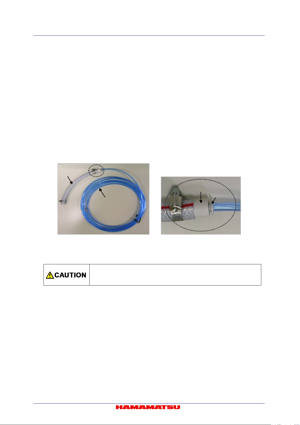
The hose has a blue hose (Interna l diameter : 4 mm / Externa l diam eter: 6 mm ) and a gray hos e
(Internal diameter: 8 mm / External diameter: 13.5 mm). (Figure 8-1)
If the hose size on circulati ng water c ooler is the same as blue hos e, rem ove gra y hose from the
joint part. The gray hose can be removed when blue hose is pulled with pushing the button of the
joint on gray hose. (Figure 8-2)
Figure 8-1 Figure 8-2
(8) Connection of the cooling water hose
•
HOSES” and Section 8-3 “DISCONNECTION OF WATER COOLING
- Stop water circulation whe n connecting / disc onnecting the hose, and turn off the power of the
camera and the circulating water cooler.
- Confirm that cooling water stops.
- Prepare water absorp tion sheet (s uch as Waste, Towel or so) and catch pan in o rder to avoi d
water drop or water splash.
(9) Deterioration of the cooling water hose
Replace the water hos e with a new on e whenever it c annot keep 0.45 L/min flow r ate for water
circulation due to the hose deteriorat ion.
21
C13440-20CU / C13440-20CU01 Instruction manual_Ver.1.3
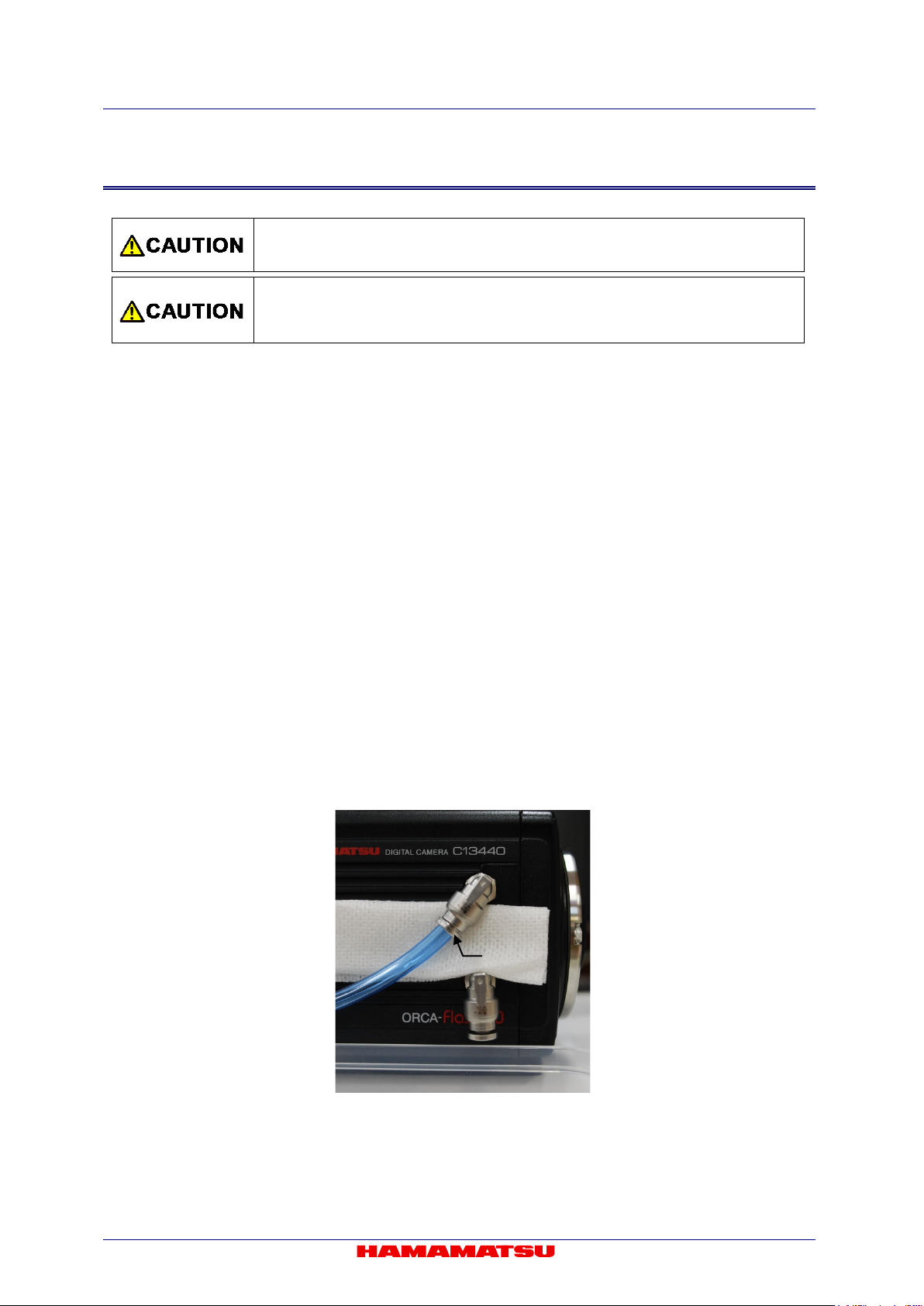
Stop the circulating water cooler when the water flow is abnormal or water
drop or splash is found.
Water cooling hose
WATER connector
8-2 CONNECTION OF WATER COOLING HOSES
Figure 8-3
1. Place the camera on the stable table.
2. Connect water cooling hose into the WATER connector on the camera.
- Insert the hose fully into the WATER connector on the camera. (as shown in Figure 8-3)
- Confirm the hose stops at it.
3. Set the camera onto a microscope (If the camera is used on the microscope).
If it is easy to connect the hose onto the camera after the camera is set onto the microscope then it is
OK to connect the hose after the camera is set on the microscope.
4. Connect the hose onto the circulating water cooler.
Follow the instruction on the circulating water cooler when you connect the hose onto the circulating
water cooler.
5. Turn on the circulating water cooler and confirm the cooling water is flowing normally.
•
22
C13440-20CU / C13440-20CU01 Instruction manual_Ver.1.3
Cooling water may be left inside the camera even after hoses are removed. In such
water onto the camera.
Button
8-3 DISCONNECTION OF WATER COOLING HOSES
• Remove the water cooling hoses only when it is necessary to remove.
•
case, remove water inside by blowing air from connectors. Be careful not to splash
1. Turn off the camera power and all peripheral devices including circulating water cooler.
2. Remove the hose on circulating water cooler side.
Follow the instructio n o n th e c i r cula ting water cooler when you di sco nne ct t he hos e f ro m t he circulating
water cooler.
3. Remove water or water drop inside the hose and the camera by air.
- Blow air from one side of hose. Prepare water absorption sheet (such as Waste, Towel or so) and
catch pan on another side of hose in order to avoid water drop or water splash.
- Blow Air until no water drop come out.
4. Remove the camera from the microscope (if the camera is used on the microscope).
It is not necessary to remove the camera from th e microscope if it is p os sibl e t o remove the hoses fr om
the camera as it is.
5. Place the camera on the stable table.
Put the lens cap on to protect the sensor.
6. Change the WATER connector direction to be downward.
Prepare water absorption sheet (such as Waste, Towel or so) and catch pan.
7. Remove hoses one by one, and wipe water.
Disconnect hoses with pushing button while being careful not to splash water.
Figure 8-4
23
C13440-20CU / C13440-20CU01 Instruction manual_Ver.1.3
Cooling method
Detail
Air-cooling method
(Default)
The heated side of a peltier element is cooled by a fan inside the camera. When
Circulating water cooler (Optional) is used for cooling the heated side of a peltier
element. Cooling does not start just turning on the camera. Cooling water
A fan inside the camera does not rotate.
9. OPERATIONS
9-1 OPERATING PRECAUTIONS
Be careful of the following w hen you operate the camera.
(1) Cooling method
Cooling of this equipment is done using a Peltier element.
With a Peltier e lement, when curr ent is s upplie d, one surfac e is cooled, and th e other surfac e is
heated. CMOS image sensor is positioned on the cooled side, and cooling is done by discharging
the heat from the heated surface.
The camera has two cooling methods, Air-cooling method and Water-cooling method.
The default of cooling m ethod is Air-c ooling. C ooling m ode c an be ch anged b y softw are wh ich is
called, “DCAM Configurator”. (refer to 9-5 “STARTUP DCAM CONFIGURATOR”).
(Forced air-cooled)
Water-cooling method
• Do not switch to water-cooling method when water-cooling is unnecessary.
the camera is turned on, the fan starts rotating and cooling is started.
circulation must be started before start operating the camera in water-cooling.
• See 8 “WATER COOLING” for instruction of water-cooling.
(2) Ambient temperature
The recommended ambient temperature for camera operation is 20 °C.
Both water-cooling or air-c ooling are available as cooling method, CMO S image sensor cooling
temperature is more stable under water cooling operation.
(3) Protection circuit
This camera’s thermoelectric cooling device is protected by a thermal protection circuit.
If the internal temperature of the camera becomes abnormally hot, the protection circuit operates
to inform the user b y a buzzer alarm (beep tone) an d lighting the camera red LED li ght while
simultaneously cutting the current supply to the Peltier element. As soon as this protection is
implemented, turn off t he power switch, unplug the AC supply. Then remove t he cause of the
overheating.
24

C13440-20CU / C13440-20CU01 Instruction manual_Ver.1.3
Note
• After cooling mode was changed, the camera memorizes the last sett ing as the def ault setting for
Configurator”. (refer to 9-5 “STARTUP DCA M CONFI GURAT OR ”)
Note
9-2 PREPARATING FO R IMAGING
Use the following procedu r e when start operating the camera.
• When you connect cables, turn off the power supply of the camera and the peripheral devices.
cooling. The present cooling mode set-up of this camera can be checked using “DCAM
9-2-1 WHEN USING AIR-COOLING
1. Connect the equipment as shown in Figure 7-1 before operating of the camera.
2. Turn on the camera.
3. Check cooling fan is operating properly and air is circulating.
• When cooling method of the camera is set by water-cooling method, the fan does not start rotating.
9-2-2 WHEN USING WATER-COOLING
1. Connect the equipment as shown in Figure 7-1 before operating of the camera.
2. Turn on the circulating water cooler.
3. Check cooling water is circulating properly.
4. Turn on the camera.
5. Turn on the cooling switch of the camera from application software.
• Please refer to the manual of application software for ON/OFF of the cooling switch of a camera.
9-3 IMAGING
Operate the camera from application software.
9-4 END OF IMAGING
Follow the procedure belo w when imaging is finished.
1. End the imaging or transmission of image data with the application software.
2. Turn off the camera and peripheral devices.
3. Turn off the circulating water cooler. (at water-cooling)
25

C13440-20CU / C13440-20CU01 Instruction manual_Ver.1.3
9-5 STARTUP DCAM CONFIGURATOR
The following is a procedure to startup “DCAM Configurator”.
1. Open “Setup.exe” in the DCAM-API software’s folder.
If the DCAM-API software is not installed on your computer, insert the media of DCAM-API software in
the slot of your computer .
When it is inserted, “DCAM-API Setup” window is displ ay ed auto mati cal ly.
2. Click on “Tools”.
3. Click on “DCAM Configurator”.
26

C13440-20CU / C13440-20CU01 Instruction manual_Ver.1.3
4. “DCAM Configurator” window is displayed. The startup is completed with this.
- Even if the camera's power supply is turned off, the state of setting is kept.
- The state of setting can confirm according to “Hardware” icon on DCAM Configurator window.
- After the startup, operate DCAM Configurator according to "DCAM Configurator Instruction manual".
The manual is displayed when the following buttons on DCAM Setup window are clicked.
27

C13440-20CU / C13440-20CU01 Instruction manual_Ver.1.3
10. DESCRIPTION OF CMOS IMAGE SENSOR
10-1 THEORY OF CMOS IMAGE SENSOR
The pixel of a CMOS image sensor is composed of the photodiode and the amplifier that converts
the charge into voltage. Entered light is converted to charge and converted to voltage in the pixel.
The voltage of each pixel is output by switching the switch one by one. ( Fig ur e 10-1)
The scientific CMOS image sensor used in this camera has an on-chip CDS (correlated double
sampling ) circ uit, which plays an important role in achieving low noise. In addition, CMOS image
sensor realizes both low noise and high speed readout simultaneously, by a split readout scheme
in which the top and the bottom halves of the sensor are readout independently, and the data of
each horizontal line is read by 2 lines of column amplifier and A/D in the top and the bottom in
parallel and simultaneou sl y.
Figure 10-1 Structure of CMOS image sensor
28

C13440-20CU / C13440-20CU01 Instruction manual_Ver.1.3
10-2 READOUT METHOD OF CMOS IMAGE SENSOR
The exposure and the readout method of CMOS image sensor which this camera adopts is
rolling shutter. In the rolling shutter, the exposure and readout are done line by line. Therefore, the
exposure timing is different on one screen. (Figure 10-2) But even if the object moves during the
exposure, the affect of roll ing sh utter is very small.
Figure 10-2 Readout timing of Roll ing sh utter
10-3 PRECAUTION WHEN USING CMOS IMAGE SENSOR
This camera uses scientific CMOS image sensor. Careful attention must be paid to the following
points when using CMOS i mag e sensor.
(1) White spot
Subjecting CMOS im age sensor to extended ex posures may cause failure in part of the silicon
wafer, resulting in white spots. Currentl y this phenomenon is not preventable. If CMOS im age
sensor is at a fixed tem perature, recurrence of the white spot increases proport ionally with the
exposure time, so this c an be rectified with dark subtraction*. Cosm ic ray may generate white
spot.
Dark subtraction: A fter a cquiri ng an im age using a certain exposure time is loaded, CMOS image sensor is exposed to darkness for
*
(2) Folding distortion
A rough-edged flicker may be visible when im aging striped patterns, lines, and s imilar subject
matter.
(3) Over light
the same amount of time, and another image is obtained. After this, the difference between the images is
determined, and the data for the dark portion of the original image is nullified.
• Be careful not to input too strong light such as high-energy laser into CMOS
image sensor because CMOS image sensor may be damaged by over light.
29

C13440-20CU / C13440-20CU01 Instruction manual_Ver.1.3
Size
Position
Horizontal
Vertical
Horizontal
Vertical
Note
Note
11. DESCRIPTION OF VARIOUS FUNCTIONS
11-1 NORMAL AREA MODE
11-1-1 CAMERA READOUT MODES (READOUT DIRECTION)
The camera reads out the im age sensor f rom the ce nter line to the top an d from the center l ine to the
bottom simultaneously (center line is depicted in red line in the diagram).
Figure 11-1 Normal area mode readout direction
11-1-2 READOUT METHODS
(1) Normal readout (Full resolution readout mode; 1×1 readout)
Perform charge readout from camera individually for all pixels.
(2) Binning readout (2×2 / 4×4 readout)
With this camera, 2×2 binning readout and 4×4 binning are available by adding the signal of
adjacent pixels in t he di git a l d omain. Binning readout is a method for achieving high sensitivity in
exchange for losing resolution.
(3) Sub-array readout
Sub-array readout is a procedure onl y a region of interest is s canned. It is possibl e to increase
the frame rate by r educin g the num ber of vertica l lines s canned. W hen a targ et ar ea is pl aced in
the center of the screen, sub-array readout can perform the fastest readout. In sub-array readout,
binning configuration is enabled.
Size and a position of the readout area can be configured according to the table below.
128 pixels 4 lines 4 pixels 4 lines
• Minimum settable step of the size and position on the table is in only the case that the camera is used
30
with DCAM.
• Please refer to 11-1-4 “FRAME RATE CALCULATION” about the frame rate of each readout mode.

C13440-20CU / C13440-20CU01 Instruction manual_Ver.1.3
Frame rate for full resolution
Camera Link
USB 3.0
16 bit
40 fps
12 bit
53 fps
8 bit
80 fps
16 bit
12 bit
8 bit
Note
11-1-3 READOUT SPEED (SCAN SPEED)
The standard scan rea dout speed c an achi eve a fram e rate of 100 fps f or full resolut ion with l ow noise
(1.0 electrons (m edian), 1.6 electrons (r.m.s.)), and the slow scan readout speed can achieve even
lower noise (0.8 electrons (median), 1.4 electrons (r.m.s.)) with a frame rate of 30 fps for full resolution.
Camera Link interf ace is necessary to transfer the image d ata with 100 fps of fast frame r ate for full
resolution.
When you use USB 3.0 interface, the frame rate is up to 40 fps (16 bit of digital output) for full resolution.
The frame rate with USB 3.0 interface will be faster when you use 12 bit or 8 bit of digital output.
Scan speed Digital output
Standard scan
Slow scan
100 fps
30 fps 30 fps
• Please refer to 11-1-4 “FRAME RATE CALCULATION” about the frame rate of each readout mode.
31
C13440-20CU / C13440-20CU01 Instruction manual_Ver.1.3
Operation modes
Calculation formula
Horizontal
Vertical
Frame rate
Free running mode
1/(Vn/2×1H)
2048
2048
100
1024
200
512
400
256
801
128
1603
64
3206
8
25 655
External trigger mode
1/(Vn/2×1H+Exp1+10×1H)
2048
2048
90
1024
164
512
278
256
425
128
579
64
707 8 877
External trigger mode
1/(Vn/2×1H+5×1H)
2048
2048
99
1024
198
512
393
256
771
128
1487
64
2773
8
11 402
Note
Note
11-1-4 FRAME RATE CALCULATION
(1) Standard scan: Camera Link
Vn = Number of vertical line (at the center area of the image sensor)
Exp1 = 1.004 ms to 10 s (input in units of seconds)
1H = 9.744 36 µs
(Edge trigger / Level trigger)
(Synchronous readout trigger)
• The calculation formula and the frame rate value of Start trigger mode (External trigger m ode) are
same as Free running mode. About this mode, refer to 11-1-6-3 “Start trigger mode”.
• The calculation formula and the frame rate value do not depend on the bit depth of digital output.
32

C13440-20CU / C13440-20CU01 Instruction manual_Ver.1.3
Horizontal
Frame
rate (fps)
Vertical
Free running
2048 × 2048
40
2048 × 512
160
2048 × 64
1282
Hn>512
Vn≤8
512 × 2048
100
512 × 512
400
512 × 8
25 655
64≤Hn≤1024
4≤Vn≤1024
32≤Hn≤512
2≤Vn≤512
External trigger
2048 ×2048
40
2048 × 512
160
Vn≤144
2048 × 64
707
2048 × 8
877
512 × 2048
90
512 × 512
278
512 × 8
877
64≤Hn≤1024
4≤Vn≤1024
32≤Hn≤512
2≤Vn≤512
External trigger
2048 × 2048
40
2048 × 512
160
2048 × 64
1282
2048 × 8
10 262
512 × 2048
99
512 × 512
393
512 × 8
11 402
64≤Hn≤1024
4≤Vn≤1024
32≤Hn≤512
2≤Vn≤512
(2) Standard scan: USB 3.0
Hn = Number of horizontal pixel
Vn = Number of vertical line (at the center area of the image sensor)
Exp1 = 1.004 ms to 10 s (input in units of seconds)
1H = 9.744 36 µs
round () = Round down to integer
roundup() = Round up to integer
1. 16 bit Digital output
Operation modes Binning
mode
1×1
2×2
4×4
mode
(Edge trigger /
Level trigger)
1×1
2×2
Hn>512
V≥16
Hn≤512
8≤Vn≤2048
Hn>512
V≥152
Hn>512
Hn≤512
8≤Vn≤2048
Calculation formula Hn × Vn
1/(round(Vn/2048/40/1H) ×1H)
1/(roundup(Vn/2048/40/1H) ×1H) 2048 × 8 9329
1/(Vn/2×1H)
1/(Vn×1H) 1024 × 1024 100
1/(Vn×2×1H) 512 × 512 100
1/(round(Vn/2048/40/1H) ×1H)
1/(Vn/2×1H+Exp1+10×1H)
1/(Vn/2×1H+Exp1+10×1H)
1/(Vn×1H+Exp1+10×1H) 1024 × 1024 90
mode
(Synchronous
readout trigger)
4×4
Hn>512
8≤Vn≤2048
1/(Vn×2×1H+Exp1+10×1H) 512 × 512 90
1/(round(Vn/2048/40/1H) ×1H)
1×1
Hn≤512
8≤Vn≤2048
2×2
4×4
1/(Vn/2×1H+5×1H)
1/(Vn×1H+5×1H) 1024 × 1024 99
1/(Vn×2×1H+5×1H) 512 × 512 99
33

C13440-20CU / C13440-20CU01 Instruction manual_Ver.1.3
Horizontal
Vertical
Free running
2048 × 2048
53
2048 × 512
212
2048 × 64
1710
Hn>512
Vn≤8
512 × 2048
100
512 × 512
400
512 × 8
25 655
64≤Hn≤1024
4≤Vn≤1024
32≤Hn≤512
2≤Vn≤512
External trigger
Hn>512
Vn≥256
2048 × 2048
53
2048 × 512
212
Hn>512
Vn≤248
2048 × 64
707
2048 × 8
877
512 × 2048
90
512 × 512
278
512 × 8
877
64≤Hn≤1024
4≤Vn≤1024
32≤Hn≤512
2≤Vn≤512
External trigger
2048 × 2048
53
2048 × 512
212
2048 × 64
1710
Hn>512
Vn≤8
512 × 2048
99
512 × 512
393
512 × 8
11 402
64≤Hn≤1024
4≤Vn≤1024
32≤Hn≤512
2≤Vn≤512
2. 12 bit Digital output
Operation modes Binning
mode
1×1
2×2
4×4
mode
(Edge trigger /
Level trigger)
1×1
2×2
Hn>512
Vn≥16
Hn≤512
8≤Vn≤2048
Hn≤512
8≤Vn≤2048
Calculation formula Hn × Vn
1/(round(Vn/2048/53/1H) ×1H)
1/(roundup(Vn/2048/53/1H) ×1H) 2048 × 8 12 827
1/(Vn/2×1H)
1/(Vn×1H) 1024 × 1024 100
1/(Vn×2×1H) 512 × 512 100
1/(round(Vn/2048/53/1H) ×1H)
1/(Vn/2×1H+Exp1+10×1H)
1/(Vn/2×1H+Exp1+10×1H)
1/(Vn×1H+Exp1+10×1H) 1024 × 1024 90
Frame
rate (fps)
mode
(Synchronous
readout trigger)
4×4
Hn>512
Vn≥16
1×1
Hn≤512
8≤Vn≤2048
2×2
4×4
1/(Vn×2×1H+Exp1+10×1H) 512 × 512 90
1/(round(Vn/2048/53/1H) ×1H)
1/(Vn/2×1H+5×1H) 2048 × 8 11 402
1/(Vn/2×1H+5×1H)
1/(Vn×1H+5×1H) 1024 × 1024 99
1/(Vn×2×1H+5×1H) 512 × 512 99
34

Horizontal
(fps)
Vertical
Free running
2048 × 2048
80
2048 × 512
320
2048 × 64
2565
Hn>512
Vn≤8
512 × 2048
100
512 × 512
400
512 × 8
25 655
64≤Hn≤1024
4≤Vn≤1024
32≤Hn≤512
2≤Vn≤512
External trigger
Hn>512
Vn≥912
2048 × 512
278
2048 × 64
707
2048 × 8
877
512 × 2048
90
512 × 512
278
512 × 8
877
64≤Hn≤1024
4≤Vn≤1024
32≤Hn≤512
2≤Vn≤512
External trigger
2048 × 2048
80
2048 × 512
320
2048 × 64
2565
Hn>512
Vn≤40
512 × 2048
99
512 × 512
393
512 × 8
11 402
64≤Hn≤1024
4≤Vn≤1024
32≤Hn≤512
2≤Vn≤512
Note
3. 8 bit Digital output
C13440-20CU / C13440-20CU01 Instruction manual_Ver.1.3
Operation modes Binning
mode
1×1
2×2
4×4
mode
(Edge trigger /
Level trigger)
1×1
2×2
Hn>512
Vn≥16
Hn≤512
8≤Vn≤2048
Hn>512
Vn≤904
Hn≤512
8≤Vn≤2048
Calculation formula Hn × Vn
1/(round(Vn/2048/80/1H) ×1H)
1/(roundup(Vn/2048/80/1H) ×1H) 2048 × 8 17 103
1/(Vn/2×1H)
1/(Vn×1H) 1024 × 1024 100
1/(Vn×2×1H) 512 × 512 100
1/(round(Vn/2048/80/1H) ×1H) 2048 × 2048 80
1/(Vn/2×1H+Exp1+10×1H)
1/(Vn/2×1H+Exp1+10×1H)
1/(Vn×1H+Exp1+10×1H) 1024 × 1024 90
Frame rate
mode
(Synchronous
readout trigger)
4×4
Hn>512
Vn≥48
1×1
Hn≤512
8≤Vn≤2048
2×2
4×4
• The calculation formula and the frame rate value of Start trigger mode (External trigger mode) are
same as Free running mode. About this mode, refer to 11-1-6-3 “Start trigger mode”.
1/(Vn×2×1H+Exp1+10×1H) 512 × 512 90
1/(round(Vn/2048/80/1H) ×1H)
1/(Vn/2×1H+5×1H) 2048 × 8 11 402
1/(Vn/2×1H+5×1H)
1/(Vn×1H+5×1H) 1024 × 1024 99
1/(Vn×2×1H+5×1H) 512 × 512 99
35
C13440-20CU / C13440-20CU01 Instruction manual_Ver.1.3
Operation modes
Calculation formula
Horizontal
Vertical
Frame rate (fps)
Free running mode
1/(Vn/2×1H)
2048
2048
30
1024
60
512
120
256
240
128
481
64
962
8
7696
External trigger mode
1/(Vn/2×1H+Exp1+10×1H)
2048
2048
27
1024
50
512
85
256
133
128
184
64
228 8 287
External trigger mode
1/(Vn/2×1H+5×1H)
2048
2048
29
1024
59
512
117
256
231
128
446
64
832
8
3420
Note
Note
(3) Slow scan: Camera Link, USB 3.0 (Common to the two interfaces)
Vn = Number of vertical line (at the center area of the image sensor)
Exp1 = 3.021 ms to 10 s (input in units of seconds)
1H = 32.4812 µs
(Edge trigger / Level trigger)
(Synchronous readout trigger)
• The calculation formula and the frame rate value of Start trigger mode (External trigger m ode) are
• The calculation formula and the frame rate value do not depend on the bit depth of digital output.
same as Free running mode. About this mode, refer to 11-1-6-3 “Start trigger mode”.
36

C13440-20CU / C13440-20CU01 Instruction manual_Ver.1.3
Setting range
Standard scan
Slow scan
Free running mode
1 ms to 10 s
3 ms to 10 s
Free running mode (at Sub-array)
38.96 µs* to 10 s
129.99 µs* to 10 s
External trigger mode
1 ms to 10 s
3 ms to 10 s
11-1-5 CONFIGURING EXPOSURE TIME
The exposure time setting can be done by the units of seconds.
The actual exposure time setting is defined by the following formula, and the camera automatically
calculates a longer and closest value from the specified exposure time setting.
(1) Standard scan
Exp1 = 1 ms to 10 s (38.96 µs to 10 s with sub-array sett ing) ( input in units of seco nds)
Exp2 = Exp1 ÷ 9.744 36 µs (round up to integer)
Calculation formula 9.744 36 µs × Exp2
(2) Slow scan
Exp1 = 3 ms to 10 s (129.99 µs to 10 s with sub-array setting) (input in units of seconds)
Exp2 = Exp1 ÷ 32.4812 µs (round up to integer)
Calculation formula 32.4812 µs × Exp2
Available setting range of the exposure time is the following.
Operation modes
38.96 µs (Standard scan) and 129.99 µs (Slow scan) is the minimum exposure time when sub-array is set to 8 lines vertically symmetric
*
(4 lines in top half and 4 lines i n botto m half ) with respect to t he hori zontall y center axis. Th e mi nimum e xposur e tim e vary depend on
vertical line number of sub-array setting.
37
C13440-20CU / C13440-20CU01 Instruction manual_Ver.1.3
Note
11-1-6 CAMERA OPERATION MODES
11-1-6-1 Free running mode
The camera has Free r unning m ode which the expos ure and read out tim ing can be set and co ntrolled
by an internal micr oprocessor. Free running mode has normal readout m ode (in which the expos ure
time is longer than the 1 frame readout time) and electrical shutter mode (in which the exposure time is
shorter than the 1 frame readout time). These readout modes are automatically switched depending on
the exposure time setting.
• Please cont act a Hamam atsu subsidiary or your local distributor for the detail of the timing information.
(1) Normal readout
The normal readout mode is suitable for observation, monitoring, field of view and focus
adjustment, and anim ation because it can operate with f ull resolution, which is faster than the
video rate*. (* 100 fps with standar d scan with Camer a Link, 40 fps with USB 3.0 (16 bit digital
output) and 30 fps with slow scan)
In addition, t he exposur e time can be extended t o collect m ore signals an d increase the signal to
noise ratio if the object is dark. In the normal readout mode, the exposure time is the same or longer
than the 1 fr ame read out tim e. In this mode, the fram e rate de pends o n the exp osure tim e, and i t
becomes frame rate = 1/exposure time. The maximum exposure time is 10 s.
Figure 11-2
38

C13440-20CU / C13440-20CU01 Instruction manual_Ver.1.3
(2) Electrical shutter
The electrical shutter mode is used to get a proper signal level when signal overflow happens due
to too much input photons in normal readout mode. In this mode, the fastest frame rate is 100 fps
(standard scan via Cam era Link), 40 fps (standard scan via USB 3.0) or 30 fps (slow scan) at full
resolution even when the exposure time is short.
Camera Link:
Figure 11-3
USB 3.0:
Figure 11-4
39
C13440-20CU / C13440-20CU01 Instruction manual_Ver.1.3
Note
0H
1H
・
・
1023H
1024H
.
.
2046H
2047H
Sens or readout
Camera Link data output
USB 3.0 da ta output
Globa l exposure timing output
Exposure
Trigger ready output
(Camera Link)
Triggerready output
(USB
3.0)
*
External trigger
* Delay: 87.7 μs Jitter: 9.74 μs (S tanda rd sc an)
* Delay: 292.33 μs Jitter: 32.48 μs (Slow scan)
11-1-6-2 External trigger mode
The camera has various external trigger functions to synchronize the camera with the external
equipment. In External trigger mode, the external equipment becomes a master and the camera
becomes a slave.
• Please contact a Hamamatsu subsidiary or your local distributor for the detail of the timing information.
(1) Edge trigger mode
The Edge trigger mode is used so that the exposure starts according to an external signal.
Exposure time is set. In this mode, the exposure of the first line begins on the edge (rising /
falling) timing of the input trigger signal into the camera. (1023H and 1024H in the following
figure) The exposure of the second line is begun after the readout time of one line passes (1022H
and 1025H in the following figure), and the exposure is begun one by one for each line.
Figure 11-5 (Ex. rising edge)
40

C13440-20CU / C13440-20CU01 Instruction manual_Ver.1.3
0H
1H
・
・
1023H
1024H
.
.
2046H
2047H
Sensor readout
Camera Link data output
USB 3.0 data output
Global e xposure ti mi ng output
Exposure
External trigger
Triggerready output
(Camera Link)
Triggerready output
(USB 3.0)
*
*Delay:87.7 μs jitter: 9.74 μs (Standard scan)
*Delay: 292.33 μs Jitter: 32.48 μs (Slow scan)
(2) Global reset Edge trigger mode
Global reset function e nables to reset t he electric c harge of all pixe ls at the sam e time. Then all
pixels can start exposure at the same time.
With this Global r eset Edge tr igger m ode, the exposu re of all pix els begins on the e dge (rising /
falling) timing of the input trigger signal into the camera.
41
Figure 11-6 (Ex. rising edge)

C13440-20CU / C13440-20CU01 Instruction manual_Ver.1.3
0H
1H
・
・
1023H
1024H
.
.
2046H
2047H
Sens or readout
Camera Link
data output
USB 3.0 da ta output
Globa l exposure timing output
Exposure
Trigger ready output
(Camera Link)
Triggerready output
(USB 3.0)
*
External trigger
* Delay: 87.7 μs
Jitter: 9.74 μs
(Standa rd s ca n)
* Delay: 292.33 μs Jitter: 32.48 μs (Slow scan)
(3) Level trigger mode
The Level trigger mode is used to control both exposure start timing and exposure time length by
inputting external tri gger pulses. In this mode, the camer a starts exposure at the star t of high or
low period of the i nput trigger pulse and stops expos ure at the end of high or low period of the
input trigger pulse. T he exam ple below is f or the trigge r level High. T he expos ure of the first line
begins when the tri gger signal becom es High, and the exposure of the second lin e begins after
the readout time of line one passes. Each exposure begins one by one for each line. The
exposure of the first line is finished when the trigger signal becom es low, and signal readout is
begun. The exposure tim e of each line is defined by the tim e that the input trigger is hig h. The
minimum trigger pulse width is 1.05 ms (standard scan) or 3.18 ms (slow scan).
Figure 11-7 (Ex. level High)
42

C13440-20CU / C13440-20CU01 Instruction manual_Ver.1.3
0H
1H
・
・
1023H
1024H
.
.
2046H
2047H
Sensor readout
Camera Link data output
USB 3.0 data output
Global exposure timing output
露光
Exposure
External Trigger
Triggerready output
(Camera Link)
Triggerready output
(USB 3.0)
*
*Delay:87.7 μs jitter: 9.74μs (Standard s can)
*Delay: 292.33 μs Jitter: 32.48 μs (Slow scan)
(4) Global reset Level trigger mode
Global reset function e nables to reset t he electric c harge of all pixe ls at the sam e time. Then all
pixels can start exposure at the same time.
The example below is for the trigger level High. With this Global r eset Level trigger mode, the
exposure of all pixels begins when the trigger signal becomes High.
Figure 11-8 (Ex. level High)
43

C13440-20CU / C13440-20CU01 Instruction manual_Ver.1.3
Sens or readout
Camera Link data output
USB 3.0 da ta output
Globa l exposure timing output
Exposure
Triggerready output
(Camera Link)
Triggerready output
(USB 3.0)
*
External trigger
0H
1H
・
・
1023H
1024H
.
.
2046H
2047H
* Delay:38.96μs Jitter :9.74 μs (Standa rd sc an)
* Delay:129.92μs Jitter :32.48 μs (Slow scan)
(5) Synchronous readout trigger mode
The Synchronous rea dout trigger mode is used for continuous imaging when it is necessary to
control the exposure start t iming of each fr ame from an external source. It is useful for conf ocal
microscopy. For example, when the camera is used with a spinning disk confocal microscope and
the camera exposur e time i s synchronized to the s pinning dis k's rotatio n speed, i t is possi ble to
eliminate uneven illumination (called banding noise) caused by variation of the spinning disk
rotation speed. Also, i t is usef ul for securing as long expos ure time as poss ible while c ontrolling
the exposure start timings by external trigger signals.
Normal operation (when the Trigger Time is set as 1.);
The Synchronous rea dout trigger mode is used for continuous imaging when it is necessary to
control the exposure start timing of each frame from an outside source and also when it is
necessary to secure as long exposure time as possible. In the Synchronous readout trigger mode,
the camera ends each exp osure, starts the readout and also, at the sam e time, starts the next
exposure at the edge of the input trigger signal (rising / falling edge). That is, the interval between
the same edges of the input trigger becomes the exposure time.
44
Figure 11-9 (Ex. rising edge)

C13440-20CU / C13440-20CU01 Instruction manual_Ver.1.3
Sens or readout
Camera Link data output
USB 3.0 da ta output
Globa l exposure timing output
Exposure
Trigger ready output
(Camera Link)
Triggerready output
(USB 3.0)
*
External trigger
0H
1H
・
・
1023H
1024H
.
.
2046H
2047H
* Delay:38.96μs Jitter :9.74 μs (Standa rd sc an)
* Delay:129.92μs Jitter :32.48 μs (Slow scan)
Trigger Times;
Also in the Synchronous readout trigger mode, synchronous readout can be controlled by
specifying, the number of timing pulses to determine the exposure time. The following figure
shows the exposure timing when the Trigger Times is set as 3.
Figure 11-10 (Trigger Times)
45

C13440-20CU / C13440-20CU01 Instruction manual_Ver.1.3
0H
1H
・
・
1023H
1024H
.
.
2046H
2047H
Sens or readout
Camera Link data output
USB 3.0 da ta output
Globa l exposure timing output
Exposure
Trigger ready output
(Camera Link)
Trigger ready output
(USB 3.0)
External trigger
* Exposur e is 100 ms or sho rter: There is invalid readout of 1 frame
Exposure is 100 ms or longer:There is Delayof 100 ms
*
Internal e x posure time
setting
11-1-6-3 Start trigger mode
Start trigger mode is to s tart operating the camera by a trigger input for a c ontinuous imaging. It is
useful to secure the frame rate as fast as possible when continuous image acquisition and not to
sacrifice the exposure time. For example, when it is necessary to measure the phenomenon after
stimulation, it is possible to start continuous image acquisition at the stimulation timing.
Start trigger mode is to start operating the camera by a trigg er input for continuous imaging, and i t
works at the high est frame rate because it is operated in internal trigger mode. In Start trigger m ode,
the camera starts ex posure and switches to internal trigger m ode by the edge of an external trigger
signal (rising / falling edge).
11-1-6-4 External trigger delay function
In most cases when a del ay between the laser pulse em ission and the exposure start is needed, a
delay unit is set between the laser and camera to control trigger timing. In each external trigger mode of
the camera, the delay can be set to the trigger signal input to the camera by command. With this setting,
a range of trigger can be arranged witho ut a de lay uni t. The ra nge f or dela y time is 0 µs t o 10 s (1 µs
steps).
46
Figure 11-11 (Ex. rising edge)

C13440-20CU / C13440-20CU01 Instruction manual_Ver.1.3
Note
Reference signal
Output signal
Camera outputs a pulse after certain delay, from the end of sensor readout.
Also the pulse width can be set.
Camera outputs a pulse after certain delay, from the beginning of readout.
Also the pulse width can be set.
Camera outputs a pulse after certain delay, from the input trigger signal.
Also the pulse width can be set.
11-1-7 TRIGGER OUTPUT
The camera provides a ran ge of trigger output signals to s ynchronize with an exter nal instrument and
the camera becomes the master and the external instrument becomes the slave.
There are three different trigger output functions as follows.
- Global exposure timing output
- Programmable timing output
- Trigger ready output
Also, it can output con tinuous High output (High output f ixed) or continuous Low output (Lo w output
fixed). They are output from Timing out connector.
(1) Global exposure timing output
It shows the global exposure timing where all lines expose at the same time. There is a case that
one event is divided into two f rames becaus e the tim ing of the exposur e in each li ne is different
for the rolling shutter. However, by using the Global exposure tim ing output the global ex posure
becomes possible for the phenomenon that happens for this period. Global exposure timing
output shows the period where all lines expose at the same time.
• There is no output signal when the exposure time is less than the frame rate.
(2) Programmable timing output
By using the programmable timing output, synchronizing external devices is simple. A system that
needs simple timing signal does not require a delay unit or pulse generator. It is possible to
program and output a puls e that has an optiona l pulse width an d an optiona l dela y time to Read
End (the end of readout timing), Vsync or Input trigger signal. The setting range for delay time is 0
µs to 10 s, and the setting range for pulse width is 1 µs to 10 s.
The relation between the parameter which can be set with e ach referenc e signal, and an outp ut
signal becomes below.
Read End
Vsync
Input trigger signal
47

C13440-20CU / C13440-20CU01 Instruction manual_Ver.1.3
Figure 11-12 Programmable timing output
(3) Trigger ready output
The trigger ready output is useful to make the frame intervals as short as possible in external
trigger mode. For example, when the camera is working in the Edge trigger mode, the next frame
can start after the previous frame exposure is done. Thus, the camera cannot accept a trigger for
the next frame during the exposure period. To reduce useless time to be as short as possible, it is
necessary to know the period when the camera can accept a tr igger for the next frame. The
trigger ready output shows the trigger ready period when the camera can accept an external
trigger in External trigger mode.
48
C13440-20CU / C13440-20CU01 Instruction manual_Ver.1.3
11-2 LIGHTSHEET READOUT MODE
Lightsheet Readout Mode is a unique feature of CMOS image sensor which provides improved
control over the rolling shut t er mec hanism.
By finely synchronizing the camera readout with the illumination scan, scattered light is rejected
allowing images of higher sign al t o noise ratios to be acquired.
The detail information of Light sheet Readout Mode is published on our website.
Website http://www.hamamatsu.com/jp/en/technology/innovation/lightsheetreadout/index.html
11-2-1 READOUT DIRECTION
The camera reads out from the center line to the top line and to the bottom line simultaneously in normal
area mode. (Figure 11-13)
The camera reads out f rom the top to the bottom line or from the bottom to the top line in Lightsheet
Readout Mode. (Figure 11-14)
Figure 11-13 Normal area mode Figure 11-14 Lightsheet Readout Mode
- Top to bottom readout (Figure 11-15): The data is readout from the top to the bottom line.
- Bottom to top readout (Figure 11-16): The data is readout from the bottom to the top line.
Figure 11-15 Top to bottom readout Figure 11-16 Bottom to top readout
49
C13440-20CU / C13440-20CU01 Instruction manual_Ver.1.3
Size
Position
Horizontal
Vertical
Horizontal
Vertical
Note
Operation modes
Calculation formula
Horizontal
Vertical
Frame rate (fps)
Common to all modes
1/(Exp1+(Vn+10)×1H)
2048
2048
49
1024
99
512
196
256
384
128
738
64
1368
8
5401
4
6841
11-2-2 ABOUT READOUT AT LIGHTSHEET READOUT MODE
(1) Readout methods
This mode can set Normal readout and Sub-array readout.
Binning readout mode is not supported at Lightsheet Readout Mode.
The size and the position of the sub-array readout can be configured according to the table
below.
128 pixels 4 lines 4 pixels 4 lines
• Minimum settable step of the size and position on the table is in only the case that the camera is used
with DCAM.
(2) Camera operation modes
This mode can use; Free r unning mode, Edge trigger mode (Exter nal trigger mode), and Start
trigger mode.
11-2-3 FRAME RATE CALCULATION
The frame rate calculation and the value of frame rate are common to all camera operation modes (Free
running mode / External trigger mode (Edge trigger) / Start trigger mode).
(1) Camera Link
Vn = Number of vertical line
Exp1 = 9.744 36 µs to 10 s (input in units of seconds to the calculation formula)
1H = 9.744 36 µs to 100 ms
(Free running mode /
External trigger mode (Edge trigger) /
Start trigger mode)
50
C13440-20CU / C13440-20CU01 Instruction manual_Ver.1.3
Horizontal
Vertical
2048 × 2048
40
2048 × 512
160
2048 × 64
1282
Hn>512
Vn≤44
4≤Vn≤2048
512 × 2048
49
512 × 512
196
Horizontal
Vertical
2048 × 2048
49
2048 × 512
196
2048 × 64
1368
2048 × 8
6841
(2) USB 3.0
Hn = Number of horizontal pixel
Vn = Number of vertical line
Exp1 = 9.744 36 µs to 10 s (input in units of seconds to the calculation formula)
1H = 9.744 36 µs to 100 ms
round () = Round down to integer
roundup() = Round up to integer
1. 16 bit Digital output
Readout
Hn>512
Vn≥48
1×1
Hn≤512
Calculation formula Hn × Vn Frame rate (fps)
1/(round(Vn/2048/40/1H) ×1H)
1/(Exp1+(Vn+10)×1H)
2. 12 bit / 8 bit Digital output
Readout
1×1
128≤Hn ≤2048
4≤Vn≤2048
Calculation formula Hn × Vn Frame rate (fps)
1/(Exp1+(Vn+10)×1H)
11-2-4 READOUT TIME OF THE HORIZONTAL LINE
2048 × 8 6841
Readout time and exposur e time can be varied with Lightsheet Readout Mod e for synchronizing the
camera readout with the illumination scan.
Vn = Number of vertical line
1H = 9.744 36 µs to 100 ms
Readout time = Vn × 1H
The range of exposure time with Lightsheet Readout Mode is as shown below.
The maximum exposur e tim e c an be dec ided acc ording t o the rea dout t im e of a fr ame, whic h is longer
than 10 s or not.
1H to (Vn × 1H) : when (Vn × 1H) < 10 s
1H to 10 s : when (Vn × 1H) ≥ 10 s
51
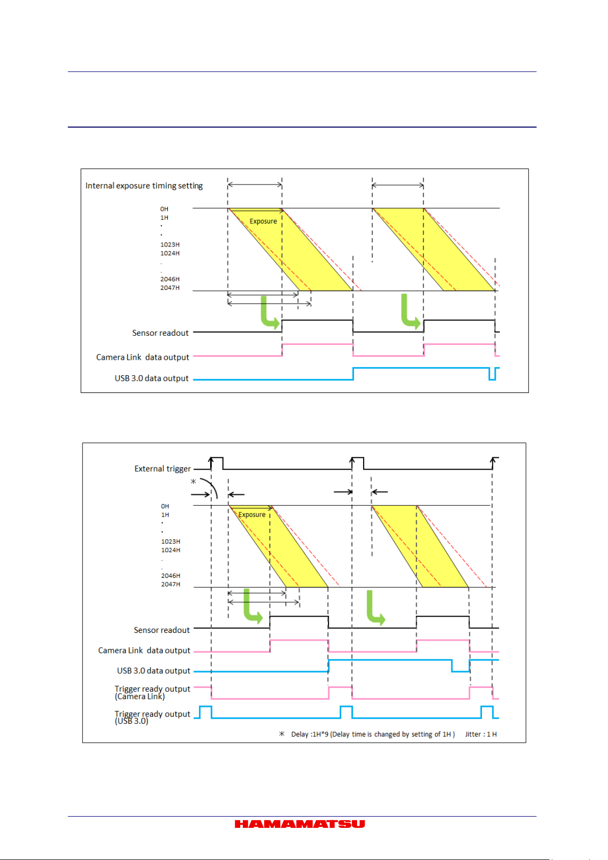
C13440-20CU / C13440-20CU01 Instruction manual_Ver.1.3
11-2-5 TIMING DIAGRAM
(1) Free running mode
Figure 11-17 (Ex. Top to bottom readout)
(2) Edge trigger mode (External trigger mode)
Figure 11-18 (Ex. rising edge, Top to bottom readout)
52
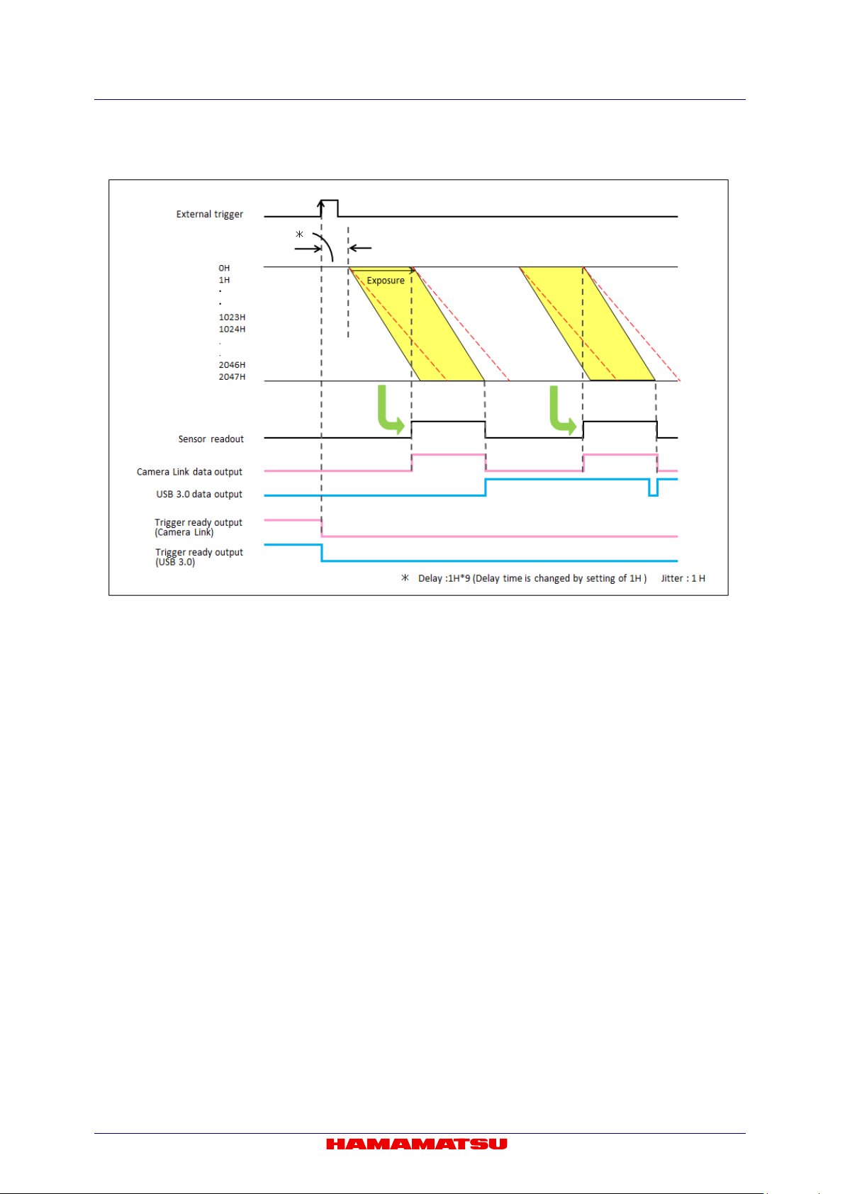
(3) Start trigger mode
C13440-20CU / C13440-20CU01 Instruction manual_Ver.1.3
Figure 11-19 (Ex. rising edge, Top to bottom readout)
53
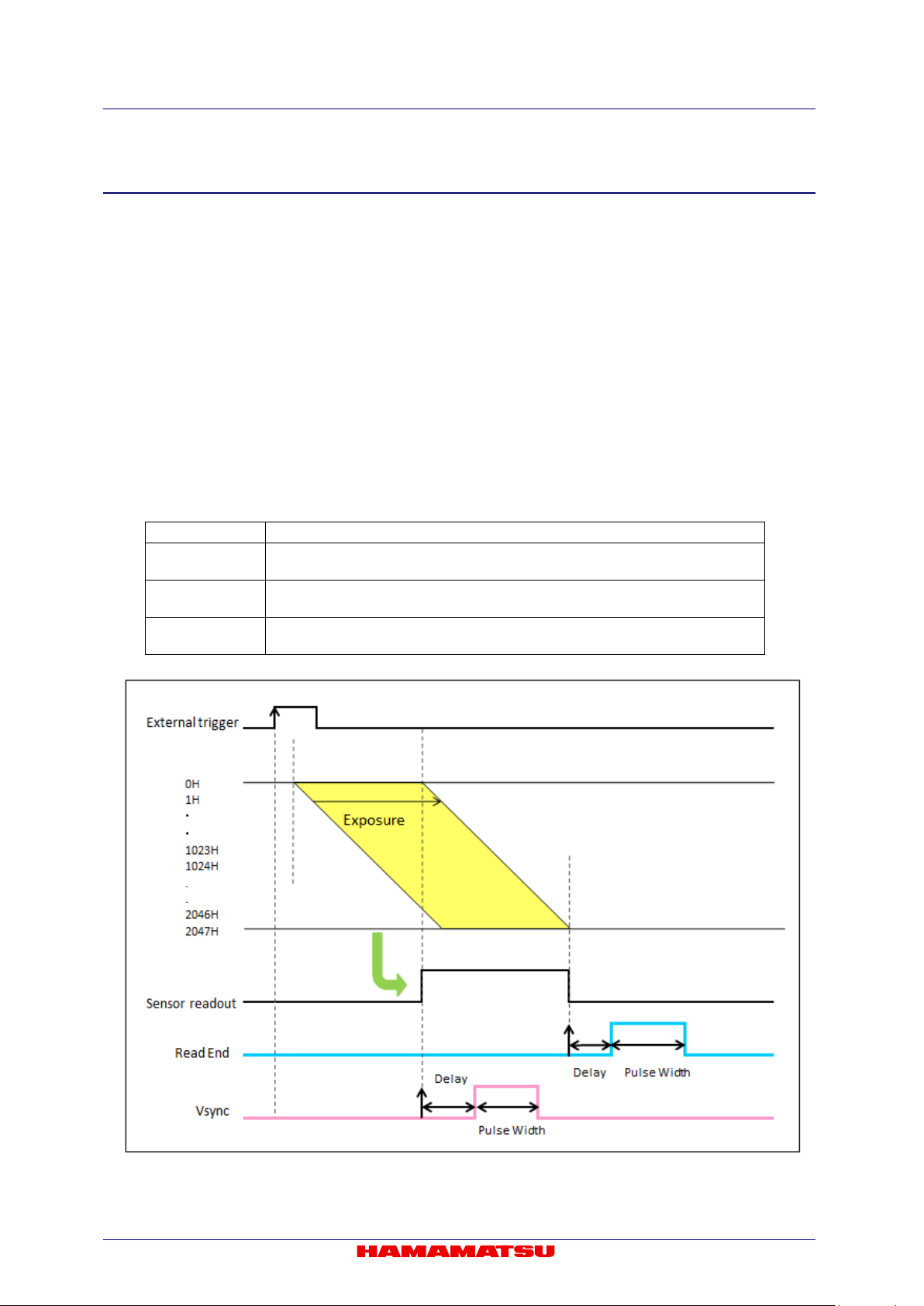
C13440-20CU / C13440-20CU01 Instruction manual_Ver.1.3
Reference signal
Output signal
Camera outputs a pulse after certain delay from the end of sensor readout.
Also the pulse width can be set.
Camera outputs a pulse after certain delay from the beginning of readout.
Also the pulse width can be set.
Camera outputs a pulse after certain delay from the Hsync which is internal
signal and whose interval time 9.744 36 µs. Also the pulse width can be set.
11-2-6 TRIGGER OUTPUT
The camera provides a range of trigger output signals with Lightsheet Readout Mode. The global
exposure timing outpu t is not provi ded, however, because there is no timing where all lines ex pose at
the same time with Lightsheet Readout Mode.
It is possible to pr ogr am and output a pulse that has a n op tio na l p ulse width and an optional de lay time
to Read End (the end of readout timing) and Vsync for programmable timing output. In addition that, it is
also possible to program an optional pulse width and an optional delay time to Hsync for programmable
timing output with Lightsheet Readout Mode.
(1) Programmable timing output
By using the programmable timing output, synchronizing with external devices is simple. A
system which needs sim ple timing signal does not require a dela y unit or pulse generator. It is
possible to program and output a p ulse that has an optional pulse width and an optional delay
time to Read End (the end of readout timing), Vsync or Hsync. The range of delay is 0 µs to 10 s,
and the range of pulse width is 1 µs to 10 s.
The relation between the parameter which can be set with e ach reference s ignal, and an output
signal becomes as shown below.
Read End
Vsync
Hsync
Figure 11-20 Programmable timing output (Top to bottom readout)
54

C13440-20CU / C13440-20CU01 Instruction manual_Ver.1.3
Figure 11-21 Programmable timing output referenced with Hsync (Top to bottom readout)
When you choose Hs ync for the reference of pr ogrammable timing output, c amera can output
some pulses before start the exposure. It is called as Pre-Hsync. You can set the number of
Pre-Hsync.
55
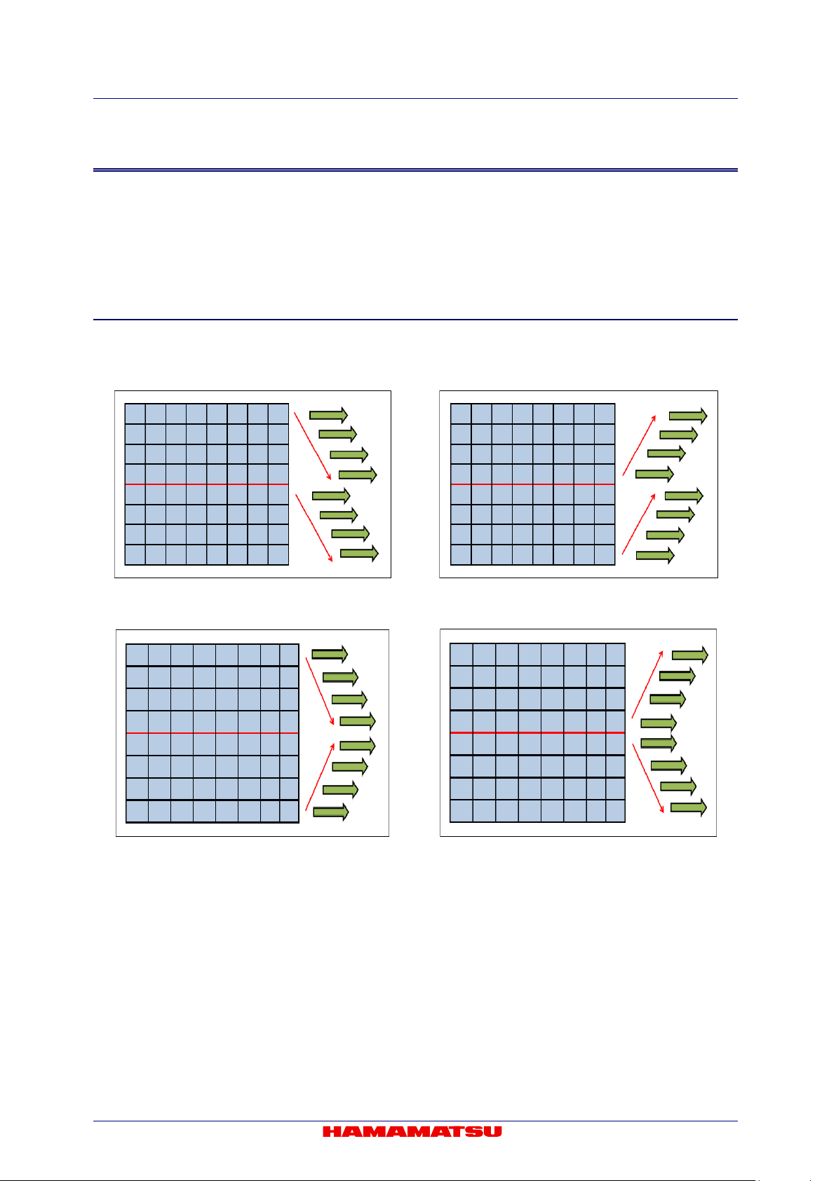
C13440-20CU / C13440-20CU01 Instruction manual_Ver.1.3
11-3 W-VIEW MODE
The exposure time and the position of sub-array readout can be set for the top half area and the
bottom half area independently in W-VIEW Mode. This function is optimized for simultaneous
image acquisition of dual wavelength images.
11-3-1 READOUT DIRECTION
The readout direction can be set for the top half area and the bottom half area independently in W-VIEW
Mode. (Figure 11-22, 23, 24, 25)
Figure 11-22 Top: top to center
/ Bottom: center to bottom
Figure 11-24 Top: top to center
/ Bottom: bottom to center
Figure 11-23 Top: center to top
/ Bottom: bottom to center
Figure 11-25 Top: center to top
/ Bottom: center to bottom
56
C13440-20CU / C13440-20CU01 Instruction manual_Ver.1.3
Size
Position
Horizontal
Vertical
Horizontal
Vertical
Note
Note
11-3-2 ABOUT READOUT AT LIGHTSHEET READOUT MODE
(1) Readout methods
This mode can set Normal readout, Binning readout, and Sub-array readout.
In sub-array mode, th e position of sub-array readout c an be set independently in the top an d
bottom half areas.
The size and the posit ion o f the s ub-arr ay read out ar ea c an be conf igur ed ac cording to the t able
below.
128 pixels 4 lines 4 pixels 4 lines
• Minimum settable step of the size and position on the table is in only the case that the camera is used
with DCAM.
• Please refer to 11-1-4 “FRAME RATE CALCULATION” about the frame rate of each readout mode.
(2) Readout speed (Scan speed)
This mode can set Standard scan and Slow scan.
(3) Camera operation modes
This mode can use; Free r unning m ode, External tri gger m ode (Edge trigger mode, G lobal res et
Edge trigger mode , Level trigger mode, Global rese t Level trigger mode, Synchronous readout
mode ), and Start trigger mode.
57

C13440-20CU / C13440-20CU01 Instruction manual_Ver.1.3
Operation modes
Calculation formula
Horizontal
Vertical
Frame rate (fps)
Free running mode
1/(Vn×1H)
2048
1024
100
512
200
256
400
128
801
64
1603
32
3206
4
25 655
External trigger mode
1/(Vn×1H+Exp1+10×1H)
2048
1024
90
512
164
256
278
128
425
64
579
32
707 4 877
External trigger mode
1/(Vn×1H+5×1H)
2048
1024
99
512
198
256
393
128
771
64
1487
32
2773
4
11 402
Note
Note
11-3-3 FRAME RATE CALCULATION
(1) Standard scan: Camera Link
Vn = Number of vertical line
Exp1 = 1.004 ms to 2 s (input in units of seconds to the calculation formula)
1H = 9.744 36 µs
(Edge trigger / Level trigger)
(Synchronous readout trigger)
• The calculation formula and the frame rate value of Start trigger mode (External trigger mode) are
• The calculation formula and the frame rate value do not depend on the bit depth of digital output.
same as Free running mode.
58

C13440-20CU / C13440-20CU01 Instruction manual_Ver.1.3
Horizontal
Vertical
Free running
2048 × 1024
40
2048 × 256
160
2048 × 32
1282
Hn>512
Vn≤4
512 × 1024
100
512 × 256
400
512 × 4
25 655
64≤Hn≤1024
2≤Vn≤512
32≤Hn≤512
1≤Vn≤256
External trigger
Hn>512
2048 × 1024
40
2048 × 256
160
Hn>512
2048 × 32
707
2048 × 4
877
512 × 1024
90
512 × 256
278
512 × 4
877
64≤Hn≤1024
2≤Vn≤512
32≤Hn≤512
1≤Vn≤256
External trigger
2048 × 1024
40
2048 × 256
160
2048 × 32
1282
Hn>512
Vn≤4
512 × 1024
99
512 × 256
393
512 × 4
11 402
64≤Hn≤1024
2≤Vn≤512
32≤Hn≤512
256
(2) Standard scan: USB 3.0
Hn = Number of horizontal pixel
Vn = Number of vertical line
Exp1 = 1.004 ms to 2 s (input in units of seconds to the calculation formula)
1H = 9.744 36 µs
round () = Round down to integer
roundup() = Round up to integer
1. 16 bit Digital output
Operation
modes
mode
mode
(Edge trigger /
Level trigger)
Binning
1×1
2×2
4×4
1×1
2×2
Hn>512
Vn≥8
Hn≤512
4≤Vn≤1024
Vn≥76
Vn≤72
Hn≤512
4≤Vn≤1024
Calculation formula Hn × Vn
1/(round(Vn/1024/40/1H) ×1H)
1/(roundup(Vn/1024/40/1H) ×1H) 2048 × 4 9329
1/(Vn×1H)
1/(Vn×2×1H) 1024 × 512 100
1/(Vn×4×1H) 512 × 256 100
1/(round(Vn/1024/40/1H) ×1H)
1/(Vn×1H+Exp1+10×1H)
1/(Vn×1H+Exp1+10×1H)
1/(Vn×2×1H+Exp1+10×1H) 1024 × 512 90
Frame rate
(fps)
mode
(Synchronous
readout trigger)
4×4
1×1
2×2
4×4
Hn>512
Vn≥8
Hn≤512
4≤Vn≤1024
≤Vn≤
1/(Vn×4×1H+Exp1+10×1H) 512 × 256 90
1/(round(Vn/1024/40/1H) ×1H)
1/(roundup(Vn/1024/40/1H) ×1H) 2048 × 4 9329
1/(Vn×1H+5×1H)
1/(Vn×2×1H+5×1H) 1024 × 512 99
1/(Vn×4×1H+5×1H) 512 × 256 99
59

C13440-20CU / C13440-20CU01 Instruction manual_Ver.1.3
Operation
modes
Horizontal
Vertical
Frame rate
(fps)
Free running
2048 × 1024
53
2048 × 256
212
2048 × 32
1710
Hn>512
Vn≤4
512 × 1024
100
512 × 256
400
512 × 4
25 655
64≤Hn≤1024
2≤Vn≤ 512
32≤Hn≤512
1≤Vn≤ 256
External trigger
2048 × 1024
53
2048 × 256
212
Vn≤124
2048 × 32
707
2048 × 4
877
512 × 1024
90
512 × 256
278
512 × 4
877
64≤Hn≤1024
2≤Vn≤ 512
32≤Hn≤512
1≤Vn≤ 256
External trigger
2048 × 1024
53
2048 × 256
212
2048 × 32
1710
Hn>512
Vn≤4
512 × 1024
99
512 × 256
393
512 × 4
11 402
64≤Hn≤1024
2≤Vn≤ 512
32≤Hn≤512
1≤Vn≤ 256
2. 12 bit Digital output
mode
mode
(Edge trigger /
Level trigger)
Binning
1×1
2×2
4×4
1×1
2×2
Hn>512
Vn≥8
Hn≤512
4≤Vn≤ 1024
Hn>512
Vn≥128
Hn>512
Hn≤512
4≤Vn≤ 1024
Calculation formula Hn × Vn
1/(round(Vn/1024/53/1H) ×1H)
1/(roundup(Vn/1024/53/1H) ×1H) 2048 × 4 12 827
1/(Vn×1H)
1/(Vn×2×1H) 1024 × 512 100
1/(Vn×4×1H) 512 × 256 100
1/(round(Vn/1024/53/1H) ×1H)
1/(Vn×1H+Exp1+10×1H)
1/(Vn×2×1H+Exp1+10×1H) 1024 × 512 90
mode
(Synchronous
readout trigger)
4×4
1×1
2×2
4×4
Hn>512
Vn≥8
Hn≤512
4≤Vn≤1024
1/(Vn×4×1H+Exp1+10×1H) 512 × 256 90
1/(round(Vn/1024/53/1H) ×1H)
2048 × 4 11 402
1/(Vn×1H+5×1H)
1/(Vn×2×1H+5×1H) 1024 × 512 99
1/(Vn×4×1H+5×1H) 512 × 256 99
60

Operation
modes
Horizontal
Vertical
Frame rate
(fps)
Free running
2048 × 1024
80
2048 × 256
320
2048 × 32
2565
Hn>512
Vn≤4
512 × 1024
100
512 × 256
400
512 × 4
25 655
64≤Hn≤1024
2≤Vn≤512
32≤Hn≤512
1≤Vn≤ 256
External trigger
Hn>512
Vn≥456
2048 × 256
278
2048 × 32
707
2048 × 4
877
512 × 1024
90
512 × 256
278
512 × 4
877
64≤Hn≤1024
2≤Vn≤ 512
32≤Hn≤512
1≤Vn≤ 256
External trigger
2048 × 1024
80
2048 × 256
320
2048 × 32
2565
Hn>512
Vn≤20
512 × 1024
99
512 × 256
393
512 × 4
11 402
64≤Hn≤1024
2≤Vn≤ 512
32≤Hn≤512
1≤Vn≤ 256
Note
3. 8 bit Digital output
C13440-20CU / C13440-20CU01 Instruction manual_Ver.1.3
mode
mode
(Edge trigger /
Level trigger)
Binning
1×1
2×2
4×4
1×1
2×2
Hn>512
Vn≥8
Hn≤512
4≤Vn≤1024
Hn>512
Vn≤452
Hn≤512
4≤Vn≤ 1024
Calculation formula Hn × Vn
1/(round(Vn/1024/80/1H) ×1H)
1/(roundup(Vn/1024/80/1H) ×1H) 2048 × 4 17 103
1/(Vn×1H)
1/(Vn×2×1H) 1024 × 512 100
1/(Vn×4×1H) 512 × 256 100
1/(round(Vn/1024/80/1H) ×1H) 2048 × 1024 80
1/(Vn×1H+Exp1+10×1H)
1/(Vn×2×1H+Exp1+10×1H) 1024 × 512 90
mode
(Synchronous
readout trigger)
4×4
Hn>512
Vn≥24
1×1
Hn≤512
4≤Vn≤ 1024
2×2
4×4
• The calculation formula and the frame rate value of Start trigger mode (External trigger mode) are
same as Free running mode.
1/(Vn×4×1H+Exp1+10×1H) 512 × 256 90
1/(round(Vn/1024/80/1H) ×1H)
2048 × 4 11 402
1/(Vn×1H+5×1H)
1/(Vn×2×1H+5×1H) 1024 × 512 99
1/(Vn×4×1H+5×1H) 512 × 256 99
61

C13440-20CU / C13440-20CU01 Instruction manual_Ver.1.3
Operation modes
Calculation formula
Horizontal
Vertical
Frame rate (fps)
Free running mode
1/(Vn×1H)
2048
1024
30
512
60
256
120
128
240
64
481
32
962 4 7696
External trigger mode
1/(Vn×1H+Exp1+10×1H)
2048
1024
27
512
50
256
85
128
133
64
184
32
228
4
287
External trigger mode
1/(Vn×1H+5×1H)
2048
1024
29
512
59
256
117
128
231
64
446
32
832
4
3420
Note
Note
(3) Slow scan: Camera Link, USB 3.0 (Common to two interfaces)
Vn = Number of vertical line
Exp1 = 3.021 ms to 6 s (input in units of seconds to the calculation formula)
1H = 32.4812 µs
(Edge trigger / Level trigger)
(Synchronous readout trigger)
• The calculation formula and the frame rate value of Start trigger mode (External trigger mode) are
• The calculation formula and the frame rate value do not depend on the bit depth of digital output.
same as Free running mode.
62

C13440-20CU / C13440-20CU01 Instruction manual_Ver.1.3
Setting range
Standard scan
Slow scan
38.96 µs* to 2 s
The same exposure time is
areas when the exposure
time is 1 ms or shorter.
129.99 µs* to 6 s
The same exposure time is
areas when the exposure
time is 3 ms or shorter.
External trigger mode
(The exposure time can be set independently
for the top and bottom half areas with Edge
trigger mode or start trigger mode.)
11-3-4 CONFIGURING EXPOSURE TIME
The exposure time can be set independently for the top and bottom half areas. The exposure time
setting can be done by the units of seconds. The actual exposure time setting is defined by the following
formula, and the camera automatically calculates a longer and closest value from the specified
exposure time setting.
(1) Standard scan
Exp1 = 1 ms to 2 s (38. 96 µ s t o 2 s with sub-array sett ing) ( in put i n un its of seconds to the c alcu lat ion for m ula)
Exp2 = Exp1÷9.744 36 µs (round up to integer) (input in units of seconds to the calculation formula)
Calculation formula 9.744 36 µs × Exp2
(2) Slow scan
Exp1 = 3 ms to 6 s (129.99 µs to 6 s with sub-array setting) (input in units of seconds to the calculation
formula)
Exp2 = Exp1÷32.4812 µs (round up to integer) (input in units of seconds to the calculation formula)
Calculation formula 32.4812 µs × Exp2
Available setting range of the exposure time is the following.
Operation modes
Free running mode 1 ms to 2 s 3 ms to 6 s
---
Free running mode (at Sub-array)
38.96 µs (Stand ard scan) and 129.99 µs (Slow scan) is the minim um exposure time whe n sub-array is set to v ertical 4 lines. The
*
minimum exposure time vary depend on vertical line number of sub-array setting.
set for the top and bottom half
1 ms to 2 s 3 ms to 6 s
set for the top and bottom half
---
63
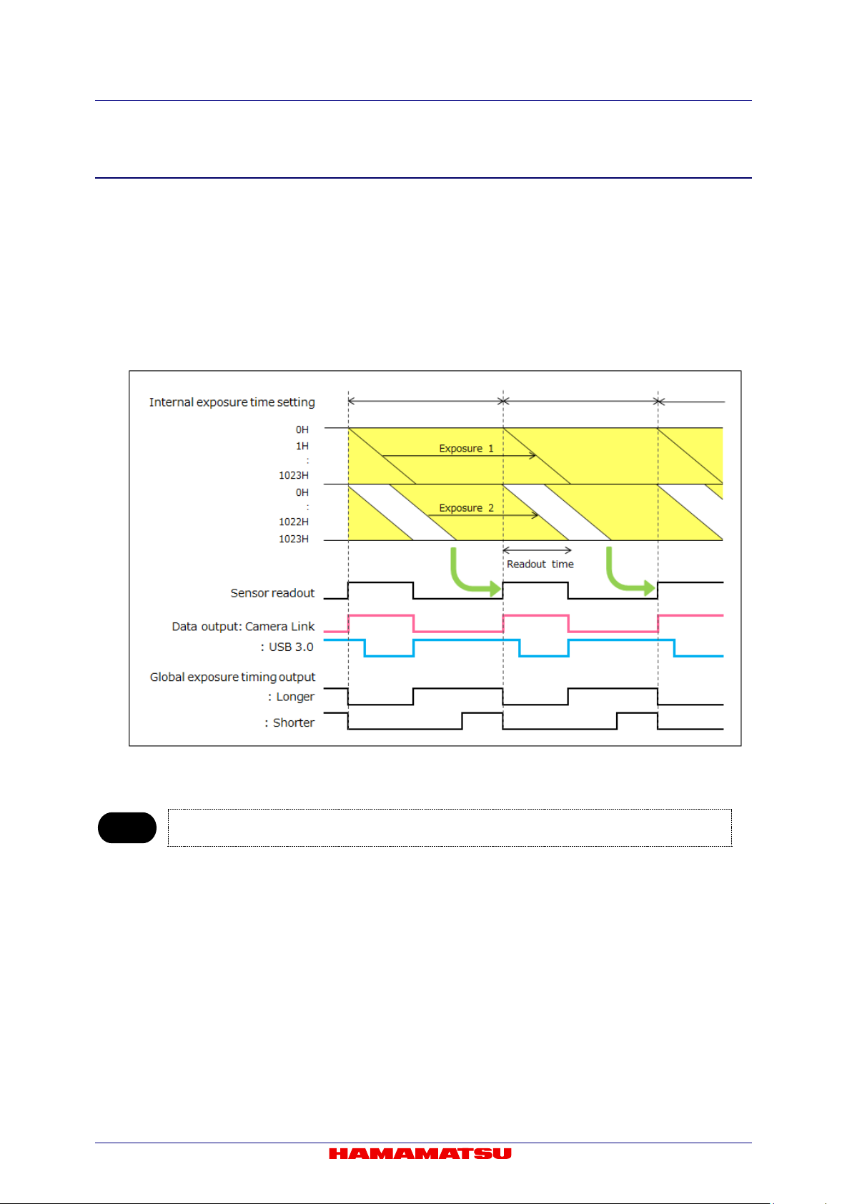
C13440-20CU / C13440-20CU01 Instruction manual_Ver.1.3
Note
11-3-5 TIMING DIAGRAM
The timing diagram in W-VIEW Mode is shown below.
When different exposure time is set for the top and bottom half areas, the end of exposure timing
becomes the same.
(1) Free running mode
Electrical shutter mode works for the half area whose exposure time is shorter than the other half
area exposure in W-VIEW Mode. When the exposure time for the both half areas are shorter than
the frame readout time, electrical shutter mode works for the both half areas.
Figure 11-26 (Ex. Top: top to center / Bottom: center to bottom)
• Please contact a Hamamatsu subsidiary or your local distributor for the detail of the timing information.
64
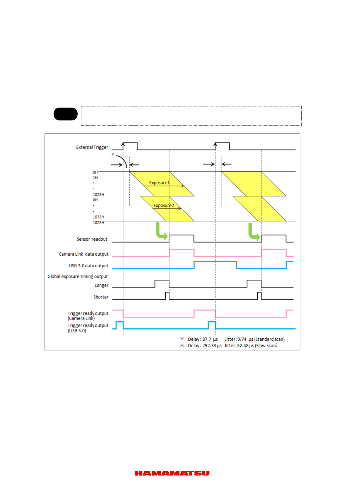
C13440-20CU / C13440-20CU01 Instruction manual_Ver.1.3
Note
• The each timing diagram of Level trigger mode, Global reset Level trigger mode and
Mode. Please refer to 11-1-6-2 “External trigger mode” and 11-1-6-3 “Start trigger mode”.
(2) External trigger mode, Start trigger mode
The exposure tim e can be set indep endently for the to p and bottom half ar eas with Edge trig ger
mode, Global reset Ed ge trigger mode and start trigger mode in W-VIEW Mode. The exposure
time for both half areas is the s ame with Level trigger mode, Global reset L ev el tri gger mode and
Synchronous readout trigger mode.
Synchronous readout trigger mode is as same as with the each timing diagram of Normal Area
Figure 11-27 Edge trigger mode (Ex. Top: top to center / Bottom: center to bottom)
65
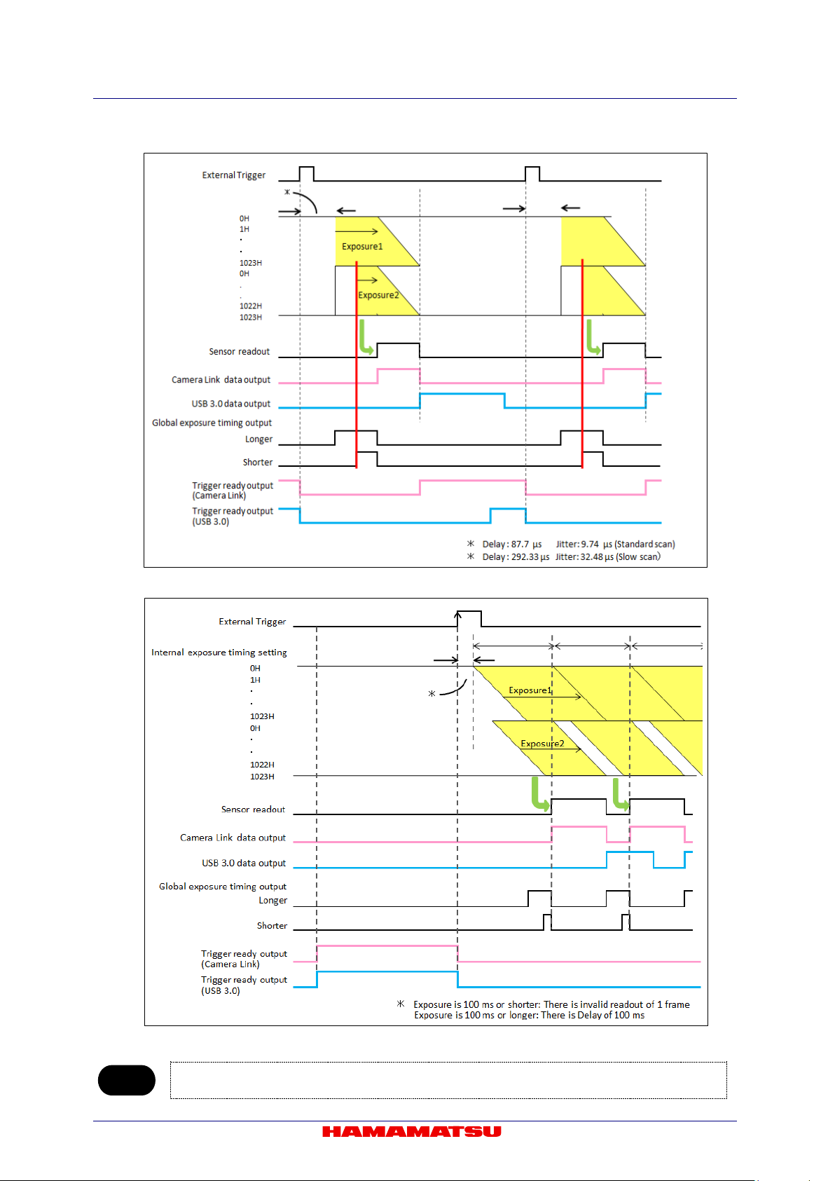
C13440-20CU / C13440-20CU01 Instruction manual_Ver.1.3
Note
Figure 11-28 Global reset Edge trigger mode (Ex. Top: top to center / Bottom: center to bottom)
Figure 11-29 Start trigger mode (Ex. Top: top to center / Bottom: center to bottom)
• Please cont act a Hamam atsu subsidiary or your local distributor for the detail of the timing information.
66

C13440-20CU / C13440-20CU01 Instruction manual_Ver.1.3
Note
Reference signal
Output signal
Camera outputs a pulse after certain delay, from the end of sensor readout.
Also the pulse width can be set.
Camera outputs a pulse after certain delay, from the beginning of readout.
Also the pulse width can be set.
Camera outputs a pulse after certain delay from the Hsync which is internal
signal and whose interval time 9.744 36 µs. Also the pulse width can be set.
11-3-6 TRIGGER OUTPUT
The camera provi des a range of trigger output signals with W-VIEW Mode. It is possible to output a
pulse that shows the period where all lines in the top or bottom half area expose at the same time.
(1) Global exposure timing output
It shows the global exposu re timing where all lines in the top or bottom half area expose at the
same time. In W-VIEW Mode, there ar e two k inds of glob al exp osure tim ing out put f or the longer
and the shorter expos ure time. This output can set either global exposure timing output f or the
longer or shorter exposure time.
• There is no output signal when the exposure time for the both top and bottom half area is shorter
than the frame readout time.
(2) Programmable timing output
By using the programmable timing output, synchronizing external devices is simple. A system that
needs simple timing signal does not require a delay unit or pulse generator. It is possible to
program and output a puls e that has an optiona l pulse width an d an optiona l delay tim e to Read
End (the end of readout timing), Vsync or Input trigger pulse. The setting range for delay time is 0
µs to 10 s, and the setting range for pulse width is 1 µs to 10 s.
The relation between the parameter which can be set with e ach referenc e signal, and an outp ut
signal becomes below.
Read End
Vsync
Input trigger pulse
Figure 11-30 Programmable timing output
67
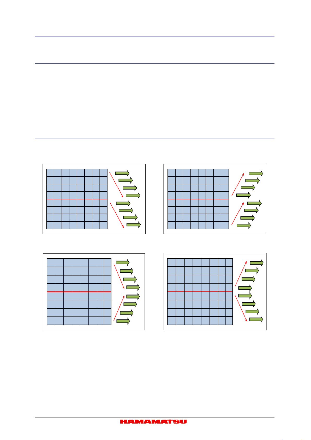
C13440-20CU / C13440-20CU01 Instruction manual_Ver.1.3
11-4 DUAL LIGHTSHEET READOUT MODE
Dual Lightsheet Readout Mode is a unique feature of CMOS image sensor which provides
improved control over the r olling shutter mechanism.
By finely synchronizing the camera readout with the illumination scan, scattered light is rejected
allowing images of higher sign al t o noise ratios to be acquired.
Dual Lightsheet Readout Mode can achieve 2 time faster frame rate than that of Lightsheet
Readout Mode. The position of sub-array readout can be set for the top half area and the bottom
half area independently in Dual Lightsheet Readout M ode.
11-4-1 READOUT DIRECTION
The readout directi on can be set for t he top half area and the b ottom half area indep endently in Dual
Lightsheet Readout Mode. (Figure 11-31, 32, 33, 34)
Figure 11-31 Top: top to center
/ Bottom: center to bottom
Figure 11-33 Top: top to center
/ Bottom: bottom to center
Figure 11-32 Top: center to top
/ Bottom: bottom to center
Figure 11-34 Top: center to top
/ Bottom: center to bottom
68
C13440-20CU / C13440-20CU01 Instruction manual_Ver.1.3
Size
Position
Horizontal
Vertical
Horizontal
Vertical
Note
Operation modes
Calculation formula
Horizontal
Vertical
Frame rate (fps)
Common to all modes
1/(Exp1+(Vn+10)×1H)
2048
1024
99
512
196
256
384
128
738
64
1368
32
2368
4
6841
11-4-2 ABOUT READOUT AT DUAL LIGHTSHEET RE ADOUT MODE
(1) Readout methods
This mode can set Normal readout and Sub-array readout.
Binning readout mode is not supported at Dual Lightsheet Readout Mode.
The size and the position of the sub-array readout can be configured according to the table
below.
128 pixels 4 lines 4 pixels 4 lines
• Minimum settable step of the size and position on the table is in only the case that the camera is used
with DCAM.
(2) Camera operation modes
This mode can use; Free r unning mode, Edge trigger mode (Exter nal trigger mode), and Start
trigger mode.
11-4-3 FRAME RATE CALCULATION
The frame rate calculation and the value of frame rate are common to all camera operation modes (Free
running mode / External trigger mode (Edge trigger) / Start trigger mode).
(1) Camera Link
Vn = Number of vertical line
Exp1 = 9.744 36 µs to 10 s (input in units of seconds to the calculation formula)
1H = 9.744 36 µs to 100 ms
(Free running mode /
External trigger mode (Edge trigger) /
Start trigger mode)
69
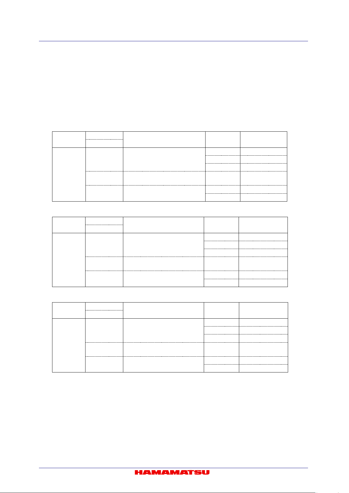
C13440-20CU / C13440-20CU01 Instruction manual_Ver.1.3
Horizontal
Vertical
2048 × 1024
40
2048 × 256
160
2048 × 32
1282
Hn>512
Vn≤4
Hn≤512
4≤Vn≤1024
512 × 1024
99
512 × 256
384
Horizontal
Vertical
2048 × 1024
53
2048 × 256
212
2048 × 32
1710
Hn>512
Vn≤12
4≤Vn≤1024
512 × 1024
99
512 × 256
384
Horizontal
Vertical
2048 × 1024
80
2048 × 256
320
2048 × 32
2386
Hn>512
Vn≤44
4≤Vn≤1024
512 × 1024
99
512 × 256
384
(2) USB 3.0
Hn = Number of horizontal pixel
Vn = Number of vertical line
Exp1 = 9.744 36 µs to 10 s (input in units of seconds to the calculation formula)
1H = 9.744 36 µs to 100 ms
round () = Round down to integer
roundup() = Round up to integer
1. 16 bit Digital output
Readout
Hn>512
Vn≥8
1×1
2. 12 bit Digital output
Readout
Hn>512
Vn≥16
1×1
Hn≤512
3. 8 bit Digital output
Calculation formula Hn × Vn Frame rate (fps)
1/(round(Vn/1024/40/1H) ×1H)
1/(Exp1+(Vn+10)×1H) 2048 × 4 6841
1/(Exp1+(Vn+10)×1H)
Calculation formula Hn × Vn Frame rate (fps)
1/(round(Vn/1024/53/1H)×1H)
1/(Exp1+(Vn+10)×1H) 2048 × 4 6841
1/(Exp1+(Vn+10)×1H)
Readout
Hn>512
Vn≥48
1×1
Hn≤512
Calculation formula Hn × Vn Frame rate (fps)
1/(round(Vn/1024/80/1H)×1H)
1/(Exp1+(Vn+10)×1H) 2048 × 4 6841
1/(Exp1+(Vn+10)×1H)
70
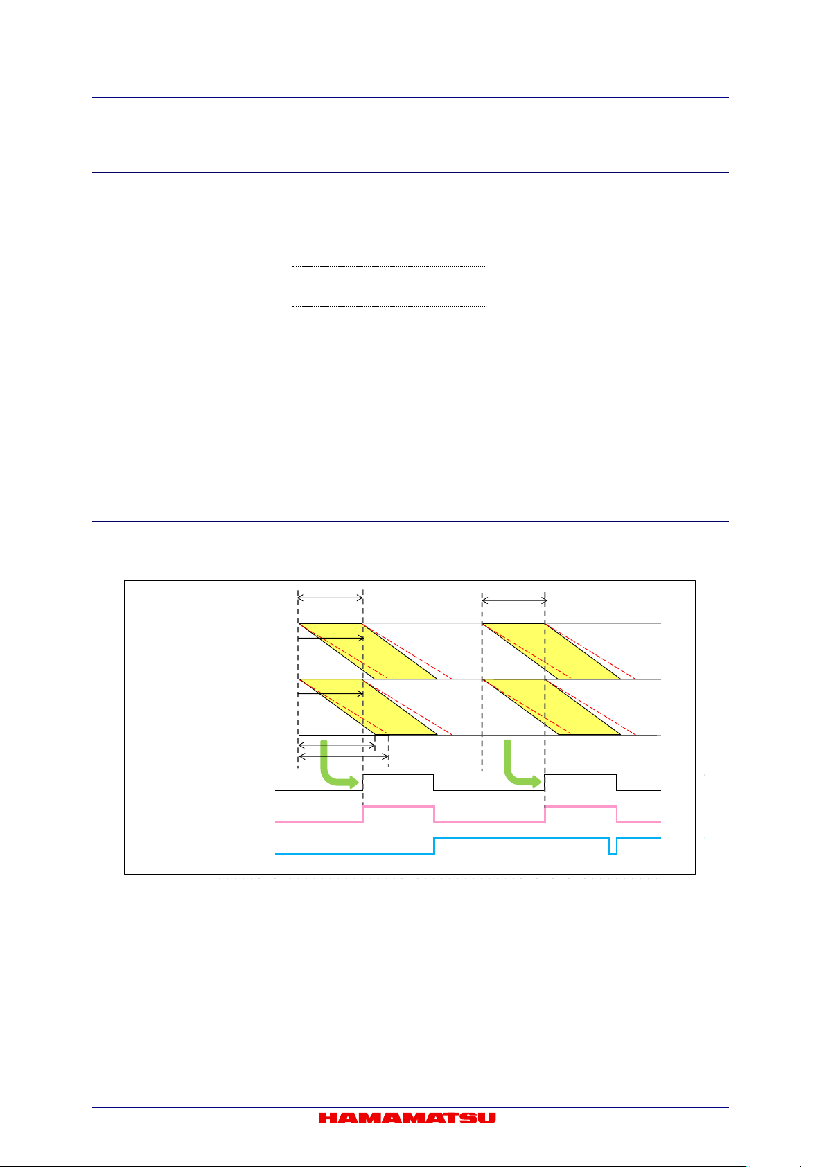
C13440-20CU / C13440-20CU01 Instruction manual_Ver.1.3
0H
1H
・
・
1023H
0H
・
・
1022H
1023H
Internal e x posure timi ng sett i ng
Exposure
Sensor readout
USB 3.0 data output
Camera Link data output
Exposure
1H can be
varied
11-4-4 READOUT TIME OF THE HORIZONTAL LINE
Readout time and exposur e time can be varied with Dual Lightsheet Readout Mode f or synchronizing
the camera readout with the illumination scan.
Vn = Number of vertical line
1H = 9.744 36 µs to 100 ms
Readout time = Vn × 1H
The range of exposure time with Lightsheet Readout Mode is as shown below.
The maximum exposur e tim e c an be dec ided acc ording t o the rea dout t im e of a fr ame, whic h is longer
than 10 s or not.
1H to (Vn × 1H) : when (Vn × 1H) < 10 s
1H to 10 s : when (Vn × 1H) ≥ 10 s
11-4-5 TIMING DIAGRAM
(1) Free running mode
Figure 11-35 (Ex. Top: top to center / Bottom: center to bottom)
71
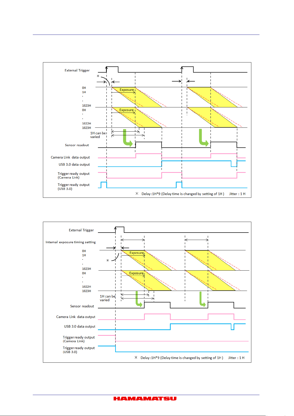
C13440-20CU / C13440-20CU01 Instruction manual_Ver.1.3
(2) Edge trigger mode
Figure 11-36 (Ex. rising edge, Top: top to center / Bottom: center to bottom)
(3) Start trigger mode
Figure 11-37 (Ex. rising edge, Top: top to center / Bottom: center to bottom)
72
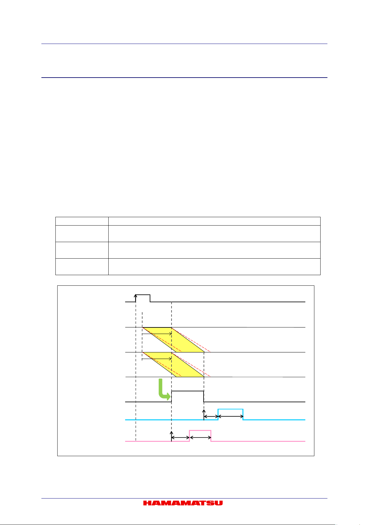
C13440-20CU / C13440-20CU01 Instruction manual_Ver.1.3
Reference signal
Output signal
Camera outputs a pulse after certain delay from the end of sensor readout.
Also the pulse width can be set.
Camera outputs a pulse after certain delay from the beginning of readout.
Also the pulse width can be set.
Camera outputs a pulse after certain delay from the Hsync which is internal signal
and whose interval time 9.744 36 µs. Also the pulse width can be set.
Exposure
Exposure
0H
1H
・
・
1023H
0H
.
.
1022H
1023H
Sensor readout
ReadEnd
Vsync
External trigger
Delay
PulseWidth
Delay
Pulse Width
11-4-6 TRIGGER OUTPUT
The camera provides a range of trigger o utput si gnals with Dual Lig htsheet Re adout Mode. The g lobal
exposure timing outp ut is not pro vided, bec ause there is no tim ing where all lines expose at the sam e
time with Dual Lightsheet Readout Mode.
It is possible to pr ogram and output a pulse that has an optional pulse width an d an o pti ona l de lay time
to Read End (the end of readout timing) and Vsync for programmable timing output. In addition that, it is
also possible to program an optional pulse width and an optional delay time to Hsync for programmable
timing output with Dual Lightsheet Readout Mode.
(1) Programmable timing output
By using the programmable timing output, synchronizing with external devices is simple. A
system which needs sim ple timing signal does not require a dela y unit or pulse generator. It is
possible to program and output a p ulse that has an optional pulse width and an optional delay
time to Read End (the end of readout timing), Vsync or Hsync. The range of delay is 0 µs to 10 s,
and the range of pulse width is 1 µs to 10 s.
The relation between the parameter which can be set with e ach reference s ignal, and an output
signal becomes as shown below.
Read End
Vsync
Hsync
Figure 11-38 Programmable timing output (Top: top to center / Bottom: center to bottom)
73

C13440-20CU / C13440-20CU01 Instruction manual_Ver.1.3
Correction Level
for white spots
Ratio of the number of pixels to be
corrected to the number of all pixels
Low
In case of 10 ms (default) or shorter exposure time
Less than 0.001 %
Exposure
Exposure
0H
1H
・
・
1023H
1024H
.
.
2046H
2047H
Hsync
External trig ger
Delay
Pulse Width
Figure 11-39 Programmable timing output referenced with Hsync (Top: top to center / Bottom: center to bottom)
When you choose Hs ync for the reference of pr ogrammable timing output, c amera can output
some pulses before start the exposure. It is called as Pre-Hsync.
11-5 REAL-TIME DEFECT PIXEL CORRECTION
There are a few pixels in CMOS i mag e sensor that have slightly higher readout noise performance
compared to surrounding pixels. And the extended exposures may cause a few white spots which
is caused by failure in part of the silicon wafer in CMOS image sensor. The camera has real-time
variant pixel correction fe atures to improve image quality.
The correction is performed in real-time without sacrificing the readout speed at all. This function
can be turned ON and OFF. (Default is ON)
User can choose the correction level for white spots depend on the exposure time.
Exposure time
High In case of 1 second or longer exposure time Approximately 0.1 %
Medium (Default) In case of 1 second or shorter exposure time Approximately 0.05 %
74

C13440-20CU / C13440-20CU01 Instruction manual_Ver.1.3
11-6 DATA REDUCTION FUNCTIONS
The camera provides 4.0 me gapixels resolution at 100 fps and 16 bit of gradation.
Then the camera outputs 800 MB of data per second, and large capacity of storage device would
be necessary to store such a large amount of data.
The camera has data reduction functions that required dat a only outputs.
11-6-1 DATA EXTRACTION
Data extraction is a function to reduce the amount of data by compressing data of unrequired area. User
can specify the requ ired area in units of 4 x4 pixe ls using camera driver soft ware “DCAM-API”. The
“DCAM-API” reconstructs the original image from the output data.
The data extraction process is performed in real-time without sacrificing the readout speed at all.
The extracted area size should be less than 3/4 of original image size.
In the case of sub-arr ay readout mode, the vertical s ub-array size should be more tha n 128 lines for
Normal Area Mode and Lights heet Readout Mode , the vertical sub-arr ay size should be m ore than 64
lines for W-VIEW Mode and Dual Lightsheet Readout Mode.
Figure 11-40
75

C13440-20CU / C13440-20CU01 Instruction manual_Ver.1.3
Note
• Please refer to 11-1-4 Normal Area Mode “FRAME RATE CALCULATION”, 11-2-3 Lightsheet
11-6-2 12 BIT / 8 BIT DIGITAL OUTPUT
The amount of dat a can be red uced by 12 b it or 8 bit d igital output. The amount of data can b e three
quarters of original 1 6 bit data and each pixel ha ve 4096 steps of gradation with 12 bit digital output.
And, with 8 bit digital output, t he amount of data can be the half of original 16 bit data and each pixe l
have 256 steps of gradat ion. W hen you use USB 3.0 interfac e, the fram e rate can be f aster with 12 bi t
and 8 bit digital output.
The steps of gradation for each pixel would be reduced with 12 bit and 8 bit digital output. However, the
look up tab le function can minimize the lack of gradation b y choosing requ ired range of intens ity level.
User can specify the range of intensity level for the look up table by 16 bit value.
Data extraction can work when the digital output is 16 bit.
Figure 11-41 LUT OFF
Figure 11-42 LUT ON
76
Readout Mode “FRAME RATE CALCULATION”, 11-3-3 W-VIEW Mode “FRAME RATE
CALCULATION” or 11-4-3 Dual Lightsheet Readout Mode “FRAME RATE CALCULATION”
about the frame rate when you use USB 3.0 interface.

C13440-20CU / C13440-20CU01 Instruction manual_Ver.1.3
Programmable
timing output
sy nchronize d with
mas te r pulse
(delay = 0 µs)
Master pulse
Interval setting for
mas te r pulse
Master pulse
Interval setting for
mas te r pulse
External trigger
Programmable
timing output
sy nchronize d with
mas te r pulse
(delay = 0 µs)
11-7 MASTER PULSE
The camera has master pulse function which can generate pulses that is independent of the
exposure or readout timing of i mage sens or. Extern al trigger mode can w or k synchroniz ed wit h the
timing pulses that the master pulse generates, except for External trigger mode in Lightsheet
Readout Mode and Dual Lightsheet Readout Mode. The master pulse can be set as a reference
signal of the programmable timing output, so it is possible to set up a synchronous system with
peripheral devices witho ut external pulse generator.
This function can be turned ON and OFF. (Default is OFF)
The master pulse supports free running mode, start trigger mode and burst mode. The range of
interval time is 10 µs to 10 s, and t he st ep is 1 µs for the master pulse.
11-7-1 OPERATION MODE
(1) Free running mode
The camera generates pulses inside of the camera during the master pulse is ON.
Figure 11-43 (Camera: Normal area, Edge trigger mode)
(2) Start trigger mode
The camera starts generating pulses inside of the camera by input trigger signal.
Figure 11-44 (Camera: Normal area, Edge trigger mode)
77

C13440-20CU / C13440-20CU01 Instruction manual_Ver.1.3
Master pulse
Interval setting for
mas te r pulse
External trigger
Programmable
timing output
sy nchronize d with
mas te r pulse
(delay = 0 µs)
(3) Burst mode
The camera starts generating pulses inside of the camera by input trigger signal, and the camera
stops generating pulses after the specified number of pulses are generated. And then, the
camera will be ready for the next input trigger signal.
Figure 11-45 (Camera: Normal area, Edge trigger mode) (The number of pulses is specified as 3)
78

C13440-20CU / C13440-20CU01 Instruction manual_Ver.1.3
• Use a plastic tweezers and take extra care not to scratch the glass window with the
window in case tweezers touch it.
12. MAINTENANCE
12-1 CARE
Perform cleaning of this e qui pment with the dry soft cloth.
• Do not wipe with a damp cloth or unclean cloth.
Then, the glass window o n t he i mag e s ensor should be cleaned according to the following.
1. Blow the dust from the glass window with an air duster.
2. Moisten a lens cleaning paper with a little ethanol, and wipe over center area of the window, gently.
3. Confirm whether dust is not left.
Attach the camera to an optics, and check if there is dust or not under the uniform light condition. If
there is dust on the image, please clean the glass window again.
• Use Lens Cleaning Paper for cleaning of glass window in front of the image sensor.
tweezers. Even with plastic tweezers, there is possibility to make scratch on the glass
• Avoid touching the surrounding parts of image area when wiping the glass window.
79

C13440-20CU / C13440-20CU01 Instruction manual_Ver.1.3
please conduct a process to soften water before use it.
Note
[Pure water]
manufacturer.
12-2 INFORMATION ON COOLING WATER FOR THE CIRCULATING
WATER COOLER
• Regarding handling cooling water and circulating water cooler, please refer t o instruction
12-2-1 WHEN USING COOLING WATER OTHER THAN RECOMMENDED
manual attached to the circulating water cooler.
• It is recommended to use soft water (except pure water) for cooling water.
• Do not use hard water for cooling. It cause inside of cooling water circulating path to be
calcified or corroded and it result lower flow rate or water flow stop. When using hard water,
• Pure water is not appropriate for cooling water. There is possibility that pure water absorb
component of cooling water path and it may cause corrosion. In addition pure water is easy to be
polluted and cause impurity, sliminess or f orming foreign s ubstances. It cause lower flow rate or
water flow stop.
[Distilled water / Deionized water]
• When using the camera inside clean room, it is poss i bl e to use dis til led water or deioni zed water
by conducting periodical check. However please notice it increases possibility of corrosion inside
cooling water path, lowering flow rate or water flow stop.
• Monthly check : Check water impurity, non-existence of sliminess, foreign particle is not mixed
with water or not adhered ins ide water path and no unusual odor. If you find any of the issues,
please exchange cooling water and clean cooling water path.
[Soft water from tap]
• It is possible to use soft water from tap with conducting periodical change of cooling water and
checkup. However please notice it increases possibility of corrosion inside cooling water path,
lowering flow rate or water flow stop.
• Monthly check : Check water impurity, non-existence of sliminess, foreign particle is not mixed
with water or not adhered ins ide water path and no unusual odor. If you find any of the issues,
please exchange cooling water and clean cooling water path.
• Exchange cooling water every 3 months.
• Clean cooling water path every 6 months.
[Bottled water]
• One example of soft water which is commonly available is mineral water (Ha rdness less than
70). Please check hardness of water by referring product information of bottled water
80

C13440-20CU / C13440-20CU01 Instruction manual_Ver.1.3
Cause
Measures
Chapter
AC adapter or other cable is loose
Reconnect the cable
7
AC adapter or other cable is broken
Replace the cable
7
Conditions
Cause
Measures
Chapter
Scratches or discoloration visible
on the screen
Image is blurred
Contact a Hamamatsu
distributor
Confirm the operating
environmental conditions
Only shadowed images are output
Lens mount cap has been
left on
Amount of light is too much
or too low
All screens overflow
Noise appears on the screen
Poor connection of internal
connector
13. TROUBLESHOOTING
If an abnormality occurs, look up the possible causes in the following tables and, if necessary,
report the details to Hamamatsu subsidiary or your local distributor.
13-1 IMAGE IS NOT TRANSFERRED
13-2 ALTHOUGH IMAGES ARE TRANSFFERED
Lens is dirty Wipe the lens 12
Lens is not focused
Condensation appear
Too much amount of light Reduce amount of light
Exogenous noise Find and remove cause
Defective circuit system
subsidiary or your local
Remove the cap
Adjust amount of light
Contact a Hamamatsu
subsidiary or your local
distributor
17
8
17
81

C13440-20CU / C13440-20CU01 Instruction manual_Ver.1.3
Camera Link interface
USB 3.0 interface
Imaging device
Scientific CMOS image sensor
Effective number of pixels
2048 (H) × 2048 (V)
Cell size
6.5 μm (H) × 6.5 µm (V)
Effective area
13.312 mm (H) × 13.312 mm (V)
Full well capacity*1
30 000 electrons
Cooling method
Peltier device + Forced air-cooled, Water-cooled
Cooling temperature
at Forced air-cooled
- 10 °C (Ambient temperature: + 20 ºC)
at Water-cooled
- 10 °C (Water temperature: + 20 ºC)
- 30 °C *
1
(at Water-cooled; Water temp. 15 °C, Ambient temp. 20 °C)
Readout time
Standard scan
10 ms
Slow scan
33 ms
Readout noise*1
Standard scan
1.0 electrons (median), 1.6 electrons (r.m.s.)
Slow scan
0.8 electrons (median), 1.4 electrons (r.m.s.)
Dark current *1
at - 10 °C
0.06 electrons/pixel/s
at - 30 °C
0.006 electrons/pixel/s
Dynamic range *2
37 000 : 1
Dark Signal Non-Uniformity (DSNU) *1
0.3 electrons r.m.s.
Photo Response
15000 electrons
0.06 % r.m.s.
700 electrons
0.3 % r.m.s.
Linearity error, low
EMV A 1288 standard
0.5 %
< 500 electrons signal
0.2 % / Less than approx. 1 electron absolute error
Conversion factor *1
0.46 electrons / count
Dark offset
100 counts (at Normal readout)
Frame rate
40 fps (16 bit)
80 fps (8 bit)
Slow scan
30 fps
30 fps
80 fps (16 bit)
160 fps (8 bit)
Slow scan
60 fps
60 fps
9329 fps (16 bit)
17 103 fps (8 bit)
Slow scan
7696 fps
7696 fps
at Horizontal 512 pixels
at center position
14. SPECIFICATIONS
14-1 CAMERA SPECIFICATIONS
(1) Electric specifications
at Maximum cooling
(at Full resolution)
Non-Uniformity *1
light range *1
at Full resolution
at 1024 lines
at center position
Standard scan 100 fps
Standard scan 200 fps
53 fps (12 bit)
106 fps (12 bit)
at 8 lines
at center position
at 8 lines
Standard scan 25 655 fps
Standard scan − 25 655 fps
Slow scan − 7696 fps
82
12 827 fps (12 bit)

C13440-20CU / C13440-20CU01 Instruction manual_Ver.1.3
Camera Link interface
USB 3.0 interface
Readout mode
Binning readout mode 2×2,4×4 (Digital binning) *3
Sub-array readout mode
pixels and horizontal 128 pixels.)
Sub-array readout mode
pixels and horizontal 128 pixels.)
Lightsheet
Readout time
20 ms to 204.8 s
Readout mode
Full/Sub-array
(Configurable for each vertical 4 pixels and horizontal 128 pixels.)
Readout direction
Top to bottom readout / Bottom to top readout
W-VIEW mode
Readout mode
Binning readout mode 2×2,4×4 (Digital binning) *3
Sub-array readout mode
position can be set independently for top and bottom area.)
Readout direction
Top to bottom readout / Bottom to top readout
(The direction can be set independently for top and bottom ar ea.)
Dual Lightsheet
Readout time
10 ms to 102.4 s
Readout mode
Full/Sub-array
the position can be set independently for top and bottom area.)
Readout direction
Top to bottom readout / Bottom to top readout
(The direction can be set independently for top and bottom area.)
Exposure time
Standard scan
1 ms to 10 s
Slow scan
3 ms to 10 s
Standard scan
38.96 µs to 10 s
Slow scan
129.99 µs to 10 s
mode
Standard scan
1 ms to 10 s
Slow scan
3 ms to 10 s
Free running mode
Standard scan
1 ms to 2 s
Slow scan
3 ms to 6 s
Free running mode
38.96 µs to 2 s
exposure time is 1ms or shorter.)
129.99 µs to 6 s
exposure time is 3ms or shorter.)
External trigger
mode *5
Standard scan
1 ms to 2 s
Lightsheet Readout Mode
Dual Lightsheet Readout Mode
External trigger
Normal area mode
Edge trigger mode / Global reset Edge trigger mode /
Start trigger mode
Lightsheet Readout
Mode
W-VIEW mode
Edge trigger mode / Global reset Edge trigger mode
(The exposure time can be set independently for top and b ottom area.)
Level trigger mode / Global reset Level trigger mode
(The exposure time is the same for top and bottom area.)
Synchronous readout trigger mode
(The exposure time is the same for top and bottom area.)
Start trigger mode
(The exposure time can be set independently for top and b ottom area.)
Dual Lightsheet
Readout Mode
Readout Mode
Readout Mode
Free running mode
Free running mode
/ Sub-array mode
External trigger
(Configurable for each vertical 4
(Configurable for each vertical 4
(Configurable for each vertical 4 pixels and horizontal 128 pixels, the
(Configurable for each vertical 4 pixels and horizont al 128 pixels, and
/ W-VIEW mode *5
/ Sub-array mode
/ W-VIEW mode *
mode / W-VIEW
Function
Standard scan
5
Slow scan
(The same exposure time is set for top and bottom areas when the
(The same exposure time is set for top and bottom areas when the
Slow scan 3 ms to 6 s
(The exposure time is the same for top and bottom area.)
Level trigger mode / Global reset Level trigger mode /
Synchronous readout trigger mode /
Edge trigger mode / Start trigger mode
9.7 µs to 10 s
83
Edge trigger mode / Start trigger mode
C13440-20CU / C13440-20CU01 Instruction manual_Ver.1.3
Camera Link interface
USB 3.0 interface
External input
(SMA connector, Camera Link)
External input
(SMA connector)
External trigger input level
3.3 V LVCMOS level
External trigger delay function
0 µs to 10 s (1 µs step)
External trigger output level
3.3 V LVCMOS level
Master pulse
Pulse mode
Free running / start trigger / burst
Pulse interval
10 µs to 10 s (1 µs step)
Digital output
16 bit / 12 bit / 8 bit
Image processing function
Real-time offset correction
Real-time gain correction
Real-time defect pixel correction
(Off / Low / Medium / High)
Data extraction
Interface
Camera Link Full configuration*4
USB 3.0 Super Speed
Lens mount
C-mount (C13440-20CU) / F-mount (C13440-20CU01)
Input power supply
DC 12 V
Typical output
---
Power consumption
55 W
Input power supply
AC 100 V to AC 240 V 50 Hz / 60 Hz 2.5 A
Typical output
DC 12 V 8.34 A
Power consumption
70 VA
Note
Ambient operating temperatur e
0 ºC to + 40 ºC
Ambient storage temperature
-10 ºC to + 50 ºC
Ambient operating humidity
30 % to 80 %, no condensation
Ambient storage humidity
Less than 90 %, no condensation
Place of operating
Indoor, altitude up to 2000 m
External signal input
External signal output
Programmable timing output 1 / Programmable timing output 2 /
Programmable timing output 3 (Continuous High or Low output)
Global exposure timing output /
Trigger ready output /
1 Typical value
*
2 Calculated from the ratio of the full well capacity and the readout noise.
*
3 Digital binning processing in the camera.
*
4 Original mode based on 80 bit mode.
*
5 The exposure time can be set independently for top and bottom area.
*
(2) Power supply specifications
a. Camera
b. AC adapter
• Fluctuations of input power supply voltages are not to exceed ± 10 % of the nominal voltage.
(3) Operating environment
84
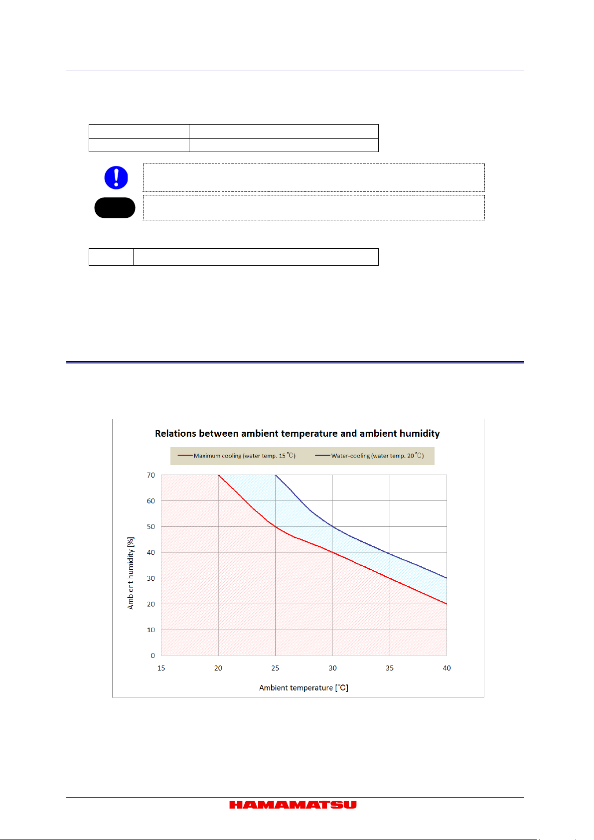
Dimensional outline
85 mm (W) × 93.5 mm (H) × 125 mm (D)
Weight
Approx. 2.2 kg (Camera only)
Note
EMC
EN61326-1: 2013 Class A
(4) Dimensional outline and weight
• Be careful not to drop off the camera or not drop underfoot when making it move
because it is approx. 2.2 kg.
• Please refer to 15 “DIMENSIONAL OUTLINES” for detail of dimensions.
(5) Applicable standards
C13440-20CU / C13440-20CU01 Instruction manual_Ver.1.3
14-2 CONDENSATION
At the Water-cooling, if ambient temperature an d ambient humidit y beco me h igh, con densat ion w il l
take place easily. Use the camera under the environment where condensation will not take place
referring to the following gr aph.
85
Figure 14-1
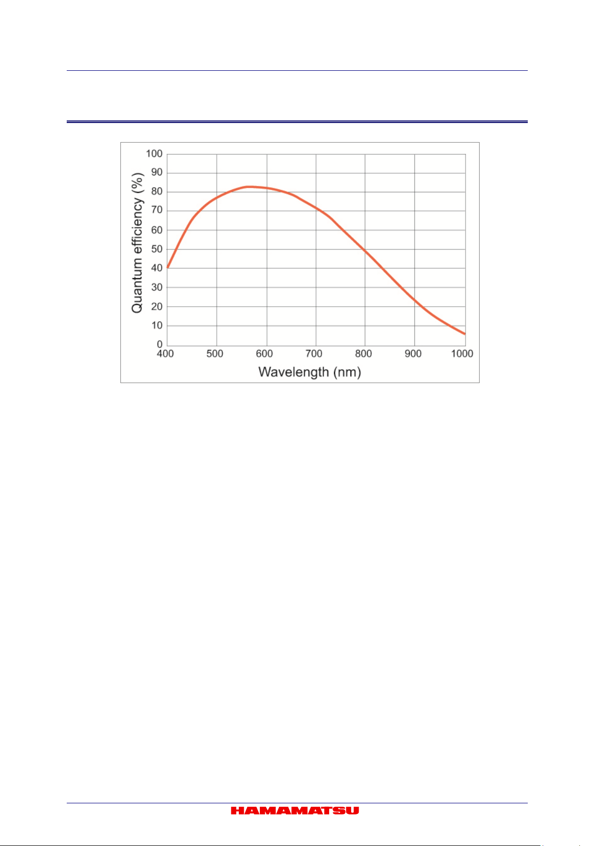
C13440-20CU / C13440-20CU01 Instruction manual_Ver.1.3
14-3 SPECTRAL RESPONSE CHARACTERISTICS ( TYP.)
Figure 14-2
86

C13440-20CU / C13440-20CU01 Instruction manual_Ver.1.3
Camera
connector
Frame grabber
connector
Channel Link
signal
Camera
connector
Frame grabber
connector
Channel Link
signal 1 1
Inner Shield
14
14
Inner Shield
2
25
X0-
15
12
X0+
3
24
X1-
16
11
X1+
4
23
X2-
17
10
X2+ 5 22
Xclk-
18 9 Xclk+ 6 21
X3-
19 8 X3+
7
20
SerTC+
20 7 SerTC-
8
19
SerTFG-
21 6 SerTFG+
9
18
CC1-
22 5 CC1+
10
17
CC2+
23 4 CC2-
11
16
CC3-
24 3 CC3+
12
15
CC4+
25 2 CC4-
13
13
Inner Shield
26
26
Inner Shield
Camera
connector
Frame grabber
connector
Channel Link
signal
Camera
connector
Frame grabber
connector
Channel Link
signal
1 1 Inner Shield
14
14
Inner Shield
2
25
Y0-
15
12
Y0+ 3 24
Y1-
16
11
Y1+
4
23
Y2-
17
10
Y2+
5
22
Yclk-
18 9 Yclk+ 6 21
Y3-
19 8 Y3+ 7 20
Terminated
20
7
Terminated
8
19
Z0-
21 6 Z0+
9
18
Z1-
22 5 Z1+
10
17
Z2-
23 4 Z2+
11
16
Zclk-
24 3 Zclk+
12
15
Z3-
25 2 Z3+
13
13
Inner Shield
26
26
Inner Shield
14-4 INTERFACE SPECIFICATIONS
(1) Camera Link interface
The camera transfers 80 bit data in parallel (8 bit x 10 port). It is an extended interface of Camera
Link full configuration Standard.
1. Pin assignments of Camera Link connector 1 (SDR-26)
2. Pin assignments of Camera Link connector 2 (SDR-26)
87

C13440-20CU / C13440-20CU01 Instruction manual_Ver.1.3
28 bit solution
pin name
Plug No.1,
Channel Link X
Plug No.2,
Channel Link Y
Plug No.3,
Channel Link Z
TxIN0
Port A0
D0_0
Port D2
D1_10
Port G5
D3_5
TxIN1
Port A1
D0_1
Port D3
D1_11
Port G6
D3_6
TxIN2
Port A2
D0_2
Port D4
D1_12
Port G7
D3_7
TxIN3
Port A3
D0_3
Port D5
D1_13
Port H0
D3_8
TxIN4
Port A4
D0_4
Port D6
D1_14
Port H1
D3_9
TxIN5
Port A5
D0_5
Port D7
D1_15 (MSB)
Port H2
D3_10
TxIN6
Port A6
D0_6
Port E0
D2_0
Port H3
D3_11
TxIN7
Port A7
D0_7
Port E1
D2_1
Port H4
D3_12
TxIN8
Port B0
D0_8
Port E2
D2_2
Port H5
D3_13
TxIN9
Port B1
D0_9
Port E3
D2_3
Port H6
D3_14
TxIN10
Port B2
D0_10
Port E4
D2_4
Port H7
D3_15 (MSB)
TxIN11
Port B3
D0_11
Port E5
D2_5
Port I0
D4_0
TxIN12
Port B4
D0_12
Port E6
D2_6
Port I1
D4_1
TxIN13
Port B5
D0_13
Port E7
D2_7
Port I2
D4_2
TxIN14
Port B6
D0_14
Port F0
D2_8
Port I3
D4_3
TxIN15
Port B7
D0_15 (MSB)
Port F1
D2_9
Port I4
D4_4
TxIN16
Port C0
D1_0
Port F2
D2_10
Port I5
D4_5
TxIN17
Port C1
D1_1
Port F3
D2_11
Port I6
D4_6
TxIN18
Port C2
D1_2
Port F4
D2_12
Port I7
D4_7
TxIN19
Port C3
D1_3
Port F5
D2_13
Port J0
D4_8
TxIN20
Port C4
D1_4
Port F6
D2_14
Port J1
D4_9
TxIN21
Port C5
D1_5
Port F7
D2_15 (MSB)
Port J2
D4_10
TxIN22
Port C6
D1_6
Port G0
D3_0
Port J3
D4_11
TxIN23
Port C7
D1_7
Port G1
D3_1
Port J4
D4_12
TxIN24
LVAL
LVAL
Port G2
D3_2
Port J5
D4_13
TxIN25
FVAL
FVAL
Port G3
D3_3
Port J6
D4_14
TxIN26
Port D0
D1_8
Port G4
D3_4
Port J7
D4_15 (MSB)
TxIN27
Port D1
D1_9
LVAL
LVAL
LVAL
LVAL
Pixel Clock
A,B,C
Pixel Clock
G,H,I,J
LVAL
(Line Valid signal)
This signal show the period during which the line part of the image data from CMOS
image sensor is in effect. Th is is “ON” when during the period the line is active.
FVAL
(Frame Valid signal)
This signal shows the period during which the vertical part of the image data from CMOS
image sensor is in effect. Th is is “ON” during the period the frame is active.
This is the image signal data from CMOS image sensor converted A/D.
Please refer to 14-5 “OUTPUT TIMING SPECIFICATIONS” for details.
3. Camera Link bit assignments
Port
Port
Port
TxCLKIn PClk
PClk Pixel Clock D,E,F PClk
D0_0 to D4_15
(Digital image data)
”D0 to D4” has 16 bit data in each. MSB shows the most significant bit.
88
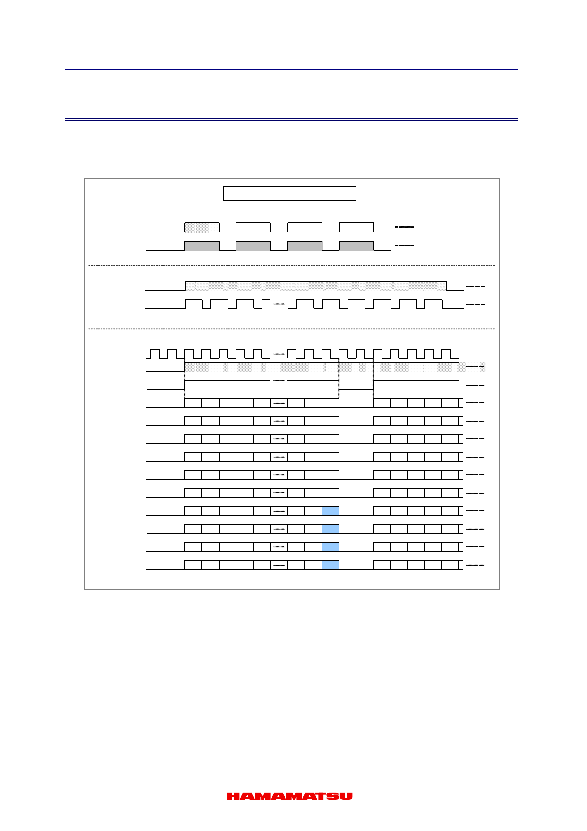
C13440-20CU / C13440-20CU01 Instruction manual_Ver.1.3
CL Port F Data
Tx Clock
C.L Fvalid
C.L Fvalid
CL Port A Data
CL Port E Data
CL Port D Data
CL Port C Data
CL Port B Data
C.L Lvalid
CL Port I Data
CL Port J Data
CL Port H Data
CL Port G Data
C.L Lvalid
CL Fvalid
CL Lvalid
85 MHz
V1023
V1024
V1022V2V2045V1V2046F1V2047
V0
F2F1F3
F4
F1
V1023
V1024
410 cloc k
4 cloc k
H0 L
H5 L
H10 L
H15 L
H20 L
H2035 L
H2040 L
H2045 L
H0 L
H5 L
H10 L
H15 L
H20 L
H0 U
H5 U
H10 U
H15 U
H20 U
H2035 U
H2040 U
H2045 U
H0 U
H5 U
H10 U
H15 U
H20 U
L: Lower byte
U: Upper byte
H1 L
H6 L
H11 L
H16 L
H21 L
H2036 L
H2041 L
H2046 L
H1 L
H6 L
H11 L
H16 L
H21 L
H1 U
H6 U
H11 U
H16 U
H21 U
H2036 U
H2041 U
H2046 U
H1 U
H6 U
H11 U
H16 U
H21 U
H2 L
H7 L
H12 L
H17 L
H22 L
H2037 L
H2042 L
H2047 L
H2 L
H7 L
H12 L
H17 L
H22 L
H2 U
H7 U
H12 U
H17 U
H22 U
H2037 U
H2042 U
H2047 U
H2 U
H7 U
H12 U
H17 U
H22 U
H3 L
H8 L
H13 L
H18 L
H23 L
H2038 L
H2043 L
0xFF
H3 L
H8 L
H13 L
H18 L
H23 L
H3 U
H8 U
H13 U
H18 U
H23 U
H2038 U
H2043 U
0xFF
H3 U
H8 U
H13 U
H18 U
H23 U
H4 L
H9 L
H14 L
H19 L
H24 L
H2039 L
H2044 L
Line Info
H4 L
H9 L
H14 L
H19 L
H24 L
H4 U
H9 U
H14 U
H19 U
H24 U
H2039 U
H2044 U
Line Info
H4 U
H9 U
H14 U
H19 U
H24 U
Camera Link Timing (Normal)
14-5 OUTPUT TIMING SPECIFICATIONS
The following shows output timing specifications for 16 bit digital output.
(1) Normal readout
89

C13440-20CU / C13440-20CU01 Instruction manual_Ver.1.3
CL Port F Data
CL Port G Data
CL Port H Data
CL Port I Data
CL Port C Data
CL Port D Data
85 MHz
CL Port E Data
CL Port J Data
C.L Lvalid
C.L Fvalid
CL Fvalid
CL Lvalid
Tx Clock
C.L Lvalid
C.L Fvalid
CL Port A Data
CL Port B Data
V511
V512
V510
V1021V1V1022
V1023
V0
F2
F1F3F4
F1
V511
V512
205 cloc k
209 cloc k
H0 L
H5 L
H10 L
H15 L
H20 L
H1010 L
H1015 L
H1020 L
H0 L
H5 L
H10 L
H15 L
H20 L
H0 U
H5 U
H10 U
H15 U
H20 U
H1010 U
H1015 U
H1020 U
H0 U
H5 U
H10 U
H15 U
H20 U
L: Lower byte
U: Upper byte
H1 L
H6 L
H11 L
H16 L
H21 L
H1011 L
H1016 L
H1021 L
H1 L
H6 L
H11 L
H16 L
H21 L
H1 U
H6 U
H11 U
H16 U
H21 U
H1011 U
H1016 U
H1021 U
H1 U
H6 U
H11 U
H16 U
H21 U
H2 L
H7 L
H12 L
H17 L
H22 L
H1012 L
H1017 L
H2 L
H7 L
H12 L
H17 L
H22 L
H2 U
H7 U
H12 U
H17 U
H22 U
H1012U
H1017 U
H2 U
H7 U
H12 U
H17 U
H22 U
H3 L
H8 L
H13 L
H18 L
H23 L
H1013 L
H1018 L
H3 L
H8 L
H13 L
H18 L
H23 L
H3 U
H8 U
H13 U
H18 U
H23 U
H1013 U
H1018 U
H3 U
H8 U
H13 U
H18 U
H23 U
H4 L
H9 L
H14 L
H19 L
H24 L
H1014 L
H1019 L
Line Info
H4 L
H9 L
H14 L
H19 L
H24 L
H4 U
H9 U
H14 U
H19 U
H24 U
H1014 U
H1019 U
Line Info
H4 U
H9 U
H14 U
H19 U
H24 U
H1022 L
H1022 U
H1023 L
H1023 U
Camera Link Timing (2x2 Binning)
F1
V2
(2) 2x2 binning readout
90
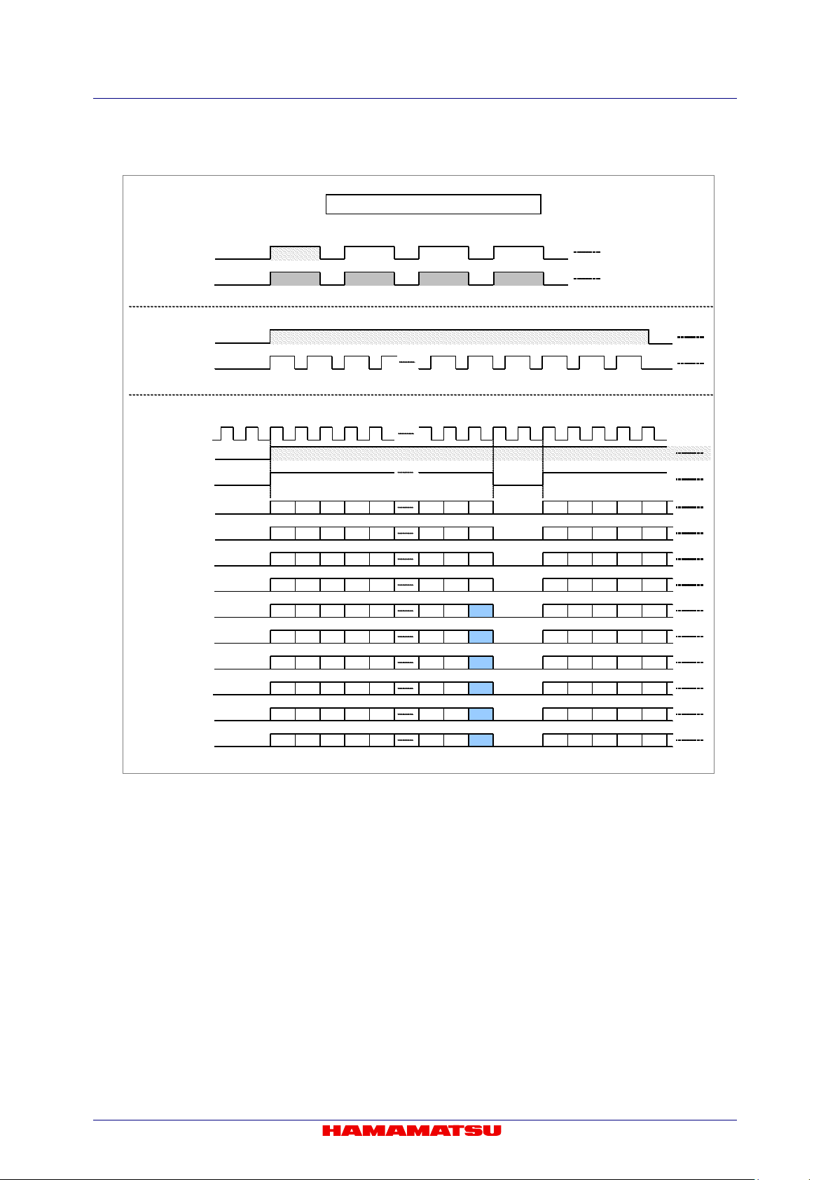
CL Port D Data
CL Port E Data
CL Port F Data
CL Lvalid
CL Port A Data
CL Port B Data
CL Port C Data
CL Port G Data
CL Port H Data
CL Port I Data
CL Port J Data
C.L Fvalid
C.L Lvalid
C.L Fvalid
CL Fvalid
Tx Clock
C.L Lvalid
85 MHz
0xFF
0xFF
0xFF
0xFF
V255
V256
V254V1V510F1V511
V0
F2F1F3
F4
F1
V255
V256
103 cloc k
311 cloc k
H0 L
H5 L
H10 L
H15 L
H20 L
H500 L
H505 L
H510 L
H0 L
H5 L
H10 L
H15 L
H20 L
H0 U
H5 U
H10 U
H15 U
H20 U
H500 U
H505 U
H510 U
H0 U
H5 U
H10 U
H15 U
H20 U
L: Lower byte
U: Upper byte
H1 L
H6 L
H11 L
H16 L
H21 L
H501 L
H506 L
H511 L
H1 L
H6 L
H11 L
H16 L
H21 L
H1 U
H6 U
H11 U
H16 U
H21 U
H501 U
H506 U
H511 U
H1 U
H6 U
H11 U
H16 U
H21 U
H2 L
H7 L
H12 L
H17 L
H22 L
H502 L
H507 L
H2 L
H7 L
H12 L
H17 L
H22 L
H2 U
H7 U
H12 U
H17 U
H22 U
H502U
H507 U
H2 U
H7 U
H12 U
H17 U
H22 U
H3 L
H8 L
H13 L
H18 L
H23 L
H503 L
H508 L
H3 L
H8 L
H13 L
H18 L
H23 L
H3 U
H8 U
H13 U
H18 U
H23 U
H503 U
H508 U
H3 U
H8 U
H13 U
H18 U
H23 U
H4 L
H9 L
H14 L
H19 L
H24 L
H504 L
H509 L
Line Info
H4 L
H9 L
H14 L
H19 L
H24 L
H4 U
H9 U
H14 U
H19 U
H24 U
H504 U
H509 U
Line Info
H4 U
H9 U
H14 U
H19 U
H24 U
Camera Link Timing (4x4 Binning)
V509
V2
(3) 4x4 binning readout
C13440-20CU / C13440-20CU01 Instruction manual_Ver.1.3
91

C13440-20CU / C13440-20CU01 Instruction manual_Ver.1.3
CL Port F Data
CL Port G Data
CL Port D Data
85 MHz
CL Port E Data
CL Port B Data
CL Port C Data
CL Port J Data
C.L Lvalid
C.L Fvalid
CL Port H Data
CL Port I Data
Tx Clock
CL Port A Data
C.L Lvalid
C.L Fvalid
CL Lvalid
CL Fvalid
V(o1+w)
F1
F2
F1F3F4F1V offset1 + width (Top region)
410 cloc k
4 cloc k
H0 L
H5 L
H10 L
H15 L
H20 L
H2035 L
H2040 L
H2045 L
H0 L
H5 L
H10 L
H15 L
H20 L
H0 U
H5 U
H10 U
H15 U
H20 U
H2035 U
H2040 U
H2045 U
H0 U
H5 U
H10 U
H15 U
H20 U
L: Lower byte
U: Upper byte
H1 L
H6 L
H11 L
H16 L
H21 L
H2036 L
H2041 L
H2046 L
H1 L
H6 L
H11 L
H16 L
H21 L
H1 U
H6 U
H11 U
H16 U
H21 U
H2036 U
H2041 U
H2046 U
H1 U
H6 U
H11 U
H16 U
H21 U
H2 L
H7 L
H12 L
H17 L
H22 L
H2037 L
H2042 L
H2047 L
H2 L
H7 L
H12 L
H17 L
H22 L
H2 U
H7 U
H12 U
H17 U
H22 U
H2037 U
H2042 U
H2047 U
H2 U
H7 U
H12 U
H17 U
H22 U
H3 L
H8 L
H13 L
H18 L
H23 L
H2038 L
H2043 L
0xFF
H3 L
H8 L
H13 L
H18 L
H23 L
H3 U
H8 U
H13 U
H18 U
H23 U
H2038 U
H2043 U
0xFF
H3 U
H8 U
H13 U
H18 U
H23 U
H4 L
H9 L
H14 L
H19 L
H24 L
H2039 L
H2044 L
Line Info
H4 L
H9 L
H14 L
H19 L
H24 L
H4 U
H9 U
H14 U
H19 U
H24 U
H2039 U
H2044 U
Line Info
H4 U
H9 U
H14 U
H19 U
H24 U
Camera Link Timing (Vertical Sub Array 2 same size regions readout)
V offset2 (Bottom region )
V(o2)
V(o1+w-1)
V(o2+w-2)
V(o1-1)
V(o2 + w- 1)
V(o1)
V(o2+w)
V(o1-2)
(4) Sub-array readout
92

C13440-20CU / C13440-20CU01 Instruction manual_Ver.1.3
15. DIMENSIONAL OUTLINES
15-1 C13440-20CU
93

C13440-20CU / C13440-20CU01 Instruction manual_Ver.1.3
15-2 C13440-20CU01
94

C13440-20CU / C13440-20CU01 Instruction manual_Ver.1.3
16. WARRANTY
Hamamatsu Photonics have fully inspected this system and checked that its performance
conforms to specifications. In the unlikely event of a breakdown or other malfunction, contact a
Hamamatsu subsidiary or your local distributor.
16-1 BASIC WARRANTY
1. Unless otherwise stated by Hamamatsu subsidiary or your local distributor, this system is under warranty for 24 months from the delivery date.
- Consumable parts, such as a fan, a mechanical shutter, and a fuse, are excepted.
- Degradation with cosmic rays and the radiation (X-rays, gamma rays, UV light, etc.) of CMOS image
sensor is excepted.
2. The warranty only covers defects in the materials and manufacturing of the system. You may be
liable for repairs during the warranty period in the event of a natural disaster or if you handle the
system contrary to the instructions in this manual, use it without due caution, or try to modify it.
3. We will repair the system or replace it, subject to availabi lity, free of char ge within t he term s of the warranty.
16-2 REPAIRS
1. If you notice anything wrong wit h the camera, confirm whether or not it is malfunctioning b y referring to the TROUBLESHOOTING in this instruction manual. You must first clarify the symptoms in order to avoid any misunderstanding or error.
2. If you have any trouble or are unclear about an ything, contac t a Hamamatsu subsidiary or your
local distributor giving the product name, serial number and details of the problem. If
Hamamatsu Photonics consider the problem to be a malfunction, we will decide whether
dispatch an engineer or have the camera returned to us for repairs.
95

C13440-20CU / C13440-20CU01 Instruction manual_Ver.1.3
Manufacturer
HAMAMATSU PHOTONICS K. K., Systems Division
812 Joko-cho, Higashi-ku, Hamamatsu City, Shizuoka Pref., 431-3196, Japa n
Telephone (81) 53-431-0124, Fax: (81) 53
-435-1574
E-mail: export@sys.hpk.co.jp
Local contact information worldwide can be found at:
www.hamamatsu.com
l The contents of this manual are subject to change without notice.
l The unaut horized duplication or distributio n of all or part of this manual is strictly
prohibited.
l If one of the following is found, please contact Hamamatsu. (refer to the local
contact information).
- Contents of the manual are illegible, incorrect or missi ng.
- Pages of the manual are missing or in the wrong order.
- The manual is unclean.
17. CONTAC T INFORMATION
96
 Loading...