

HAMAMATSU R5900U Datasheet
FEATURES
● High Speed Response
● Wide Dynamic Range
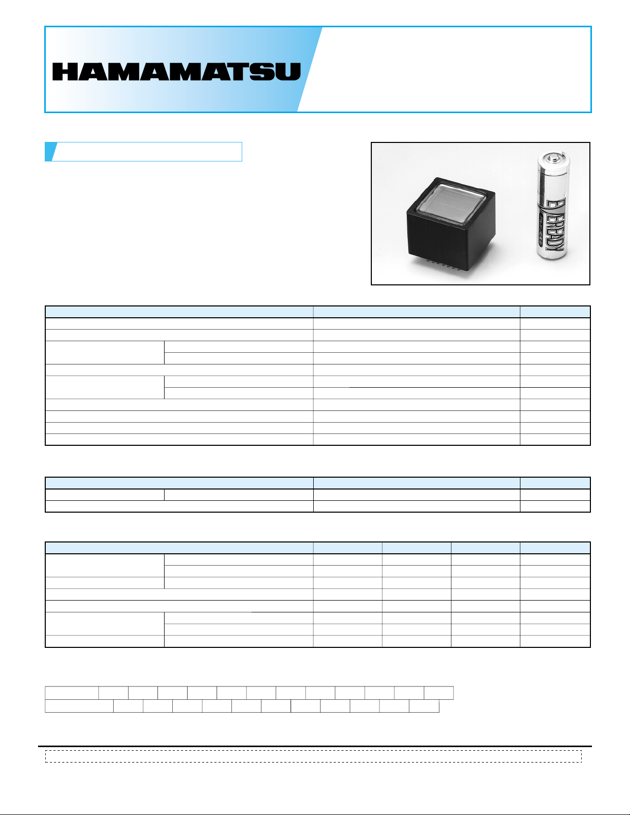
● Compact
GENERAL
Parameter Description/Value Unit
Spectral Response
Peak Wavelength
Photocathode
Window Material
Dynode
Weight
Suitable Socket
Operating Ambient Temperature
Storage Temperature
Material
Minimum Effective Area
Structure
Number of Stages
PHOTOMULTIPLIER TUBES
R5900U
300 to 650
420
Bialkali
18 × 18
Borosilicate glass
Metal channel dynode
10
Approx. 25.5
E678-32B (sold separately)
-30 to +50
-30 to +50
nm
nm
—
mm
—
—
—
g
—
°C
°C
MAXIMUM RATINGS (Absolute Maximum Values)
Parameter Value Unit
Supply Voltage
Average Anode Current
Between Anode and Cathode
900
0.1
V
mA
CHARACTERISTICS (at 25 °C)
Parameter Min. Unit
Cathode Sensitivity
Anode Sensitivity
Gain
Anode Dark Current (after 30 min storage in darkness)
Time Response
Pulse Linearity
NOTE: Anode characteristics are measured with the voltage distribution ratio shown below.
Luminous (2856 K)
Blue Sensitivity Index (CS 5-58)
Luminous (2856 K)
Anode Pulse Rise Time
Transit Time Spread (FWHM)
±2 % deviation
60
7
30
5.0 × 10
—
—
—
—
5
Typ.
70
8
140
2.0 × 10
2
1.5
0.26
30
Max.
—
—
6
—
—
20
—
—
—
µA/lm
—
A/lm
—
nA
ns
ns
mA
VOLTAGE DISTRIBUTION RATIO AND SUPPLY VOLTAGE
Electrodes
Ratio
Supply Voltage: 800 Vdc, K: Cathode, Dy: Dynode, P: Anode
Subject to local technical requirements and regulat ions, availability of products included in this promotional material may vary. Please consult with our sales office.
Information furnished by HAMA MATSU is believed to be reliable. However, no respon sibility is assumed for possible inaccuracies or omissions. Specifications are
subject to change without notice. No patent rights are granted to any of the circuits described herein.
KDy1
1.5
1.5
Dy2
1.5
Dy3
Dy41Dy51Dy61Dy7
Dy8 Dy9 Dy10 P
11
111
2003 Hamamatsu Photonics K.K.
©
PHOTOMULTIPLIER TUBE R5900U
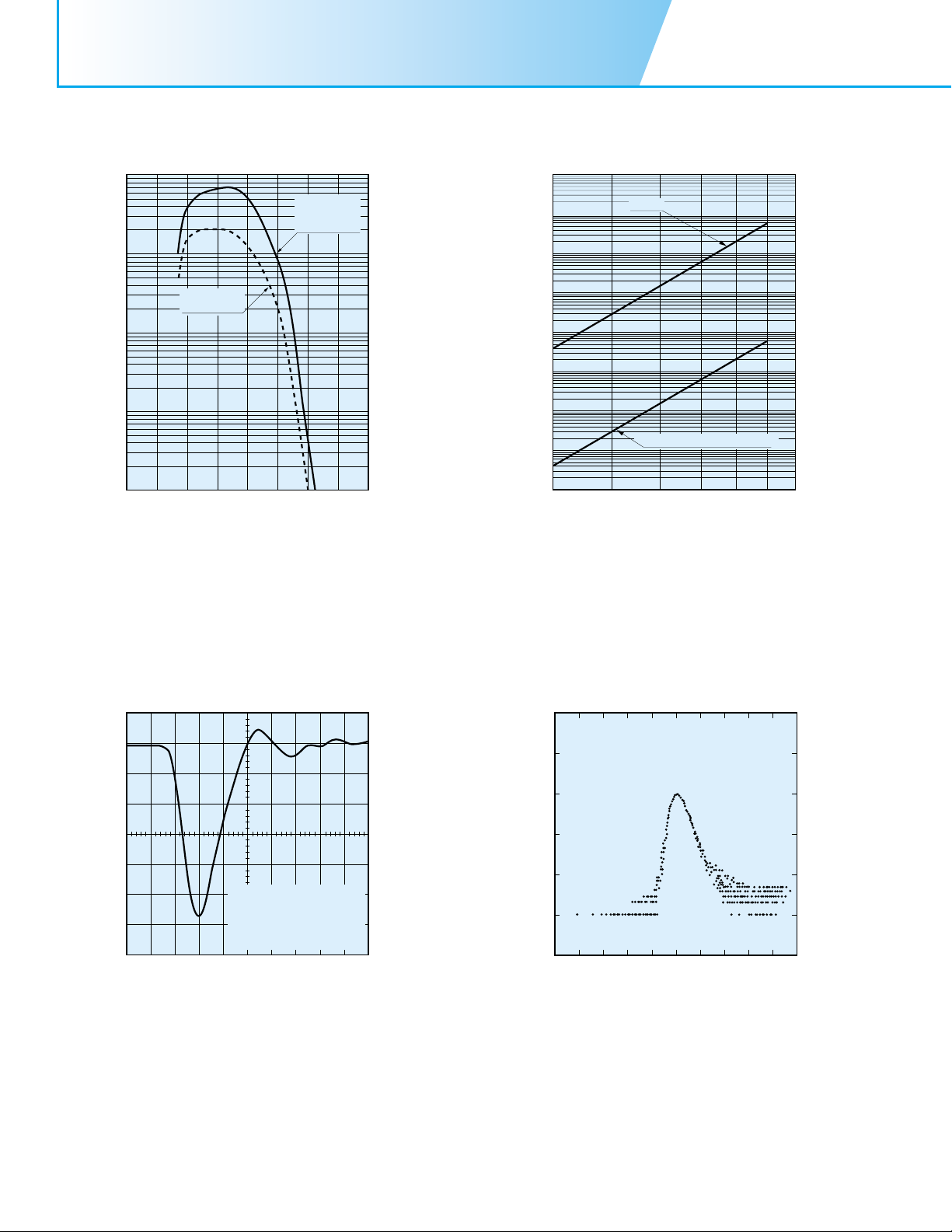
Figure 1: Typical Spectral Response
TPMHB0266EA
100
10
QUANTUM
EFFICIENCY
1
QUANTUM EFFICIENCY (%)
0.1
CATHODE RADIANT SENSITIVITY (mA/W)
0.01
100 200 300 400 500 600 700 800 900
WAVELENGTH (nm)
CATHODE
RADIANT
SENSITIVITY
Figure 2: Typical Gain and Anode Dark Current
TPMHB0265ED
8
10
7
10
6
10
5
10
4
10
GAIN
3
10
2
10
1
10
0
10
400 600 800 1000
GAIN
ANODE DARK CURRENT
SUPPLY VOLTAGE (V)
10
10
10
10
10
10
10
10
10
-4
-5
-6
-7
-8
-9
ANODE DARK CURRENT (A)
-10
-11
-12
Figure 3: Typical Time Response
TPMHB0263ED
(20 mV/div.)
SUPPLY VOLTAGE=-800 V
RISE TIME=1532 ps
FALL TIME=2691 ps
WIDTH=3163 ps
L=50 Ω
R
TIME (2 ns/div.)
Figure 4: Typical T.T.S. Characteristic
TPMHB0264EB
SUPPLY VOLTAGE=-800 V
FWHM=256 ps
4
10
FWTM=527 ps
3
10
2
10
1
10
RELATIVE COUNTS
0
10
TIME (0.5 ns/div.)
 Loading...