

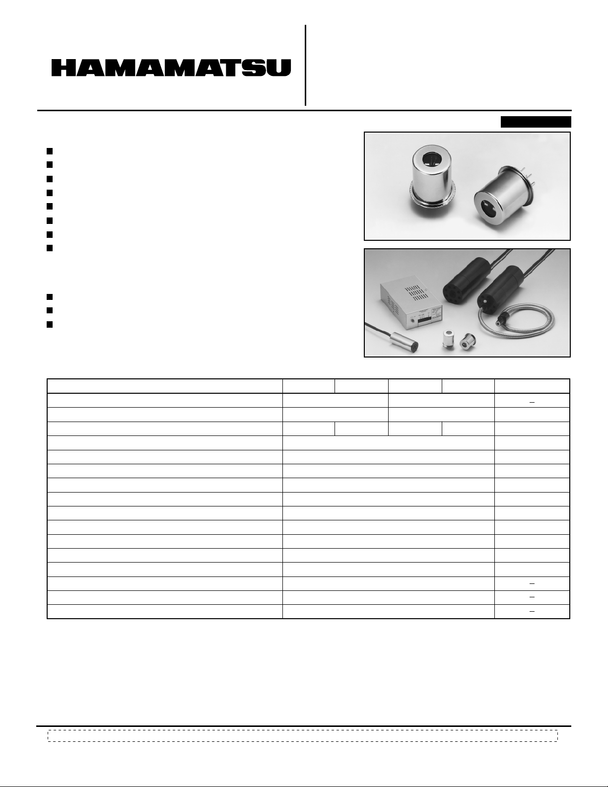
60 W XENON FLASH LAMP SERIES
BUILT-IN REFLECTIVE MIRROR
L7684, L7685/L6604, L6605
FEATURES
High Stability: Fluctuation (p-p) 3 % Max.
High Input Energy: 1 J (per one flash)
7
Long Life: 8 × 10
Short Arc: 3 mm
Spectral Distribution: 190 nm to 2000 nm (Sapphire glass window type)
High Repetition Rate Meeting TV rate: 60 Hz
Short flash pulse-width (FWHM): 2.90 µs (at 2 µF, 1000 V)
Built-in Reflective Mirror/1.5 Times Brighter (L7684, L7685)
APPLICATIONS
Stroboscope for FA High Speed Image Processing
Industrial Stroboscope
Pollution Analysis etc.
flashes Min.
PATENT PENDING
TLSXF0105
CHARACTERISTICS
Parameter L7684 L6604
Window Material
Spectral Distribution
Reflective Mirror
Operating Voltage
Recommended Operating Voltage
Trigger Voltage
Trigger Capacitor Value
Maximum Average Input Energy (single)
Maximum Average Input (continuous)
Arc Length
Maximum Repetition Rate
Output Fluctuation (p-p)
Guaranteed Life (number of flashes)
Applicable Trigger Socket
Applicable Power Supply
Applicable Cooling Jacket
NOTE:
a
Average input energy (E) is calculated by the below formula.
E = 1/2 CV
V: Main discharge voltage (V dc)
b
Average Input(W) is calculated by the below formula.
W = E × f f: Repetition frequency (repetition rate)
c
At 1 J/flash (60 W) input. Maximum 100 Hz operation is possible with keeping average input 60 W or lower.
d
At 1 J/flash input energy (60 W) with using the cooling jacket of E6611.
e
It is necessary to have an additional external capacitor E7289-01 for 60 W input, when 1 J/flash input energy is needed.
f
It has to be used for the operation more than 15 W input.
c
2
E: Average input energy (J) C: Main discharge capacitor value (F)
d
b
a
L7685 L6605
Borosilicate Glass
240 to 2000
Single Crystal Sapphire Glass
190 to 2000
Built-in — Built-in —
300 to 1000
700 to 1000
5 to 10
0.22
1
60
3
60
3
7
8 × 10
E6647
e
C6096
f
E6611
TLSXF0103
Unit
nm
V
V
kV
µF
J
W
mm
Hz
% Max.
flashes Min.
Subject to local technical requirements and regulations, availability of products included in this promotional material may vary. Please consult with our sales office.
Information furnished by HAMAMATSU is believed to be reliable. However, no responsibility is assumed for possible inaccuracies or omissions. Specifications are
subject to change without notice. No patent rights are granted to any of the circuits described herein. ©2001 Hamamatsu Photonics K.K
60 W XENON FLASH LAMP SERIES
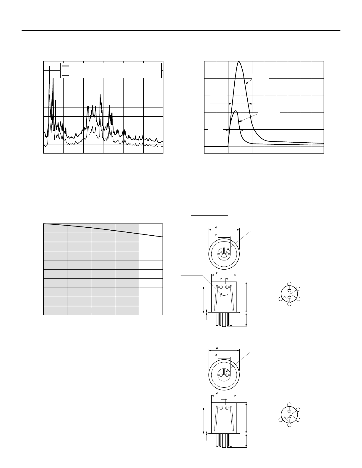
Figure 1: Spectral Distribution
TLSXB0104EA TLSXB0084EA
2
1.8
1.6
60 W Xenon Flash Lamp Buit-in Reflective Mirror L7685
(1 J: 2 µF/1 kV)
60 W Xenon Flash Lamp L6605 (1 J: 2 µF/1 kV)
1.4
1.2
1
0.8
0.6
RELATIVE INTENSITY
0.4
0.2
0
200
300 400 500 600 700 800
WAVELENGTH (nm)
Figure 3: Life Characteristics
Figure 2: Flash Pulse Waveforms (L6604, L6605)
100
80
60
FWHM
1 J/flash
2.90 µs
40
0.15 J/flash
FWHM
1.75 µs
20
RELATIVE INTENSITY (%)
0
TIME (2 µs/div.)
Figure 4: Dimensional Outline (Unit: mm)
TLSXB0083EC
100
80
60
40
RELATIVE INTENSITY (%)
20
GUARANTEED LIFE
0
04 × 10
2 × 10
7
(100)
MAIN DISCHARGE VOLTAGE: 1 kV
MAIN DISCHARGE CAPACITOR: 2 µF
REPETITION RATE: 60 Hz
INPUT ENERGY: 1 J / FLASH
The life end is defined as the time when the radiant intensity falls to
50 % of its initial value or when the output flutuation exceeds ±3 %.
7
(200)
6 × 10
(300)
7
NUMBER OF FLASHES
*( ) OPERATING TIME [h]
8 × 10
(400)
L7684, L7685
REFLECTIVE
MIRROR
25.8 ± 0.5
1 × 10
(500)
8
1.3
7
(Built-in Reflective Mirror)
34.8 ± 0.5
14.3 ± 0.15
28.9 ± 0.3
3
OUTPUT WINDOW
34.5 ± 0.5
15 MAX.
PIN CONNECTION
(BOTTOM VIEW)
ANODE
1
5
SPARKER
4
CATHODE
TRIGGER PROBE
2
3
TRIGGER PROBE
TLSXA0082EA
L6604, L6605
34.8±0.5
14.3±0.15
28.9±0.3
3
OUTPUT WINDOW
PIN CONNECTION
(BOTTOM VIEW)
ANODE
1
TRIGGER PROBE
2
25.8±0.5
1.3
34.5±0.5
15 MAX.
SPARKER
5
4
CATHODE
3
TRIGGER PROBE
TLSXA0049EC

RELATED PRODUCTS
Trigger Socket E6647
In order to operate a Xenon flash lamp, it is necessary to supply the prescribed high voltage between anode and
cathode, and to trigger probes. To facilitate the above operation, the trigger socket consists of high voltage
transformer and voltage divider resistors and capacitors chain to supply the appropriate pulse voltage to each
electrode.
As E6647 radiates heat from its metal parts during the operation due to the input energy, it is recommended to
use a cooling fan to keep the surface temperature of the metal parts at less than 50 °C.
Dimensional Outline (Unit: mm)
14.8±0.1
METAL
RED : MAIN DISCHAGE VOLTAGE
WHITE : TRIGGER VOLTAGE
BLACK : GND (MAIN)
BROWN : GND (TRIGGER)
5.5
73.5±2.0 500±20
28.5±1.0
TLSXA0050EB
Power Supply C6096
C6096 has large capability to operate the lamp stable in spite of its compact dimensions. At 1 J/flash input energy
becomes over 0.05 J, it is necessary to have an additional external capacitor E7289-01 (option).
Specifications Dimensional Outline (Unit: mm)
Parameter Description/Value
Main
Powe r
Supply
Trigger
Section
Trigger
Input
Section
Input Voltage (dc)
Power Consumption
Cooling
Weight
NOTE:
Output Voltage (dc) 300 V to 1000 V
Output Capacity
Stability
Main Supply Capacitor
Trigger Output Voltage
Trigger Capacitor
Trigger Type
Repetition Rate
Trigger Input Impedance
Input Waveform
Input Voltage
g
The range of 700 V to 1000 V is used for the operation
of 60 W Xenon flash lamp series.
h
In the case of connects temperature sensor lead lines
from the cooling jacket, the output voltage becomes 0 V
when the temperature sensor turns on.
At 1 J/flash input energy becomes over 0.05 J, it is
i
necessary to have an additional external capacitor
E7289-01 (option).
j
Don’t use beyond 60 Hz at the operation of 60 W input.
k
A trigger pulse voltage is supplied to each electrode at
the same time as an input trigger signal rise.
108±2
g
h
60 W Max.
±1 % Max.
i
0.1 µF
180 V Typ.
0.22 µF
Internal / External
j
10 Hz to 100 Hz
1 kΩ
k
Rectangular Waveform
5 V
24 V ± 1.2 V
90 W
Not Required
Approx. 550 g
49±2
2-M3
140.0±0.5
80.0±0.5 14
174±3
100.0±0.5
24.0±0.5
2-M3
TLSXA0051EA

60 W XENON FLASH LAMP SERIES
Cooling Jacket E6611
This cooling jacket is exclusively designed for 60 W Xenon flash lamps will keep the temperature of the lamp and
electric parts such as the trigger socket at less than maximum ratings and maintain at even temperature by a built-in
cooling fan, and offers the stable operation of the lamp. It has to be used for the operation of more than 15 W input.
Dimensional Outline (Unit:mm)
* The temperature sensor is for the protection of a lamp, a
SETTING HOLES 2-M4 × P1
LAMP
TRIGGER SOCKET
35 65
TEMPERATURE SENSOR*
TRIGGER SOCKET
SHIELD CABLE
COOLING FAN (RATING : 24 V, 0.1 A dc)
trigger socket and a power supply, when it detects an abnornal high temperature due to out of work with the cooling fan. When lead lines of temperature sensor are connected to the protection circuit terminal of C6096 exclusive power supply, the power supply will stop its operation.
62.0±0.5
M23 × P1
21.0±1.5
175±3
Light-Guides
Light-guides are effective to guide the output light into a
place where does not allow to direct irradiation due to its
construction or to plural places simultaneously. A short arc of
60 W Xenon flash lamps allows the light into the light-guides
effectively. As the standard option, two types of light guide
are available from us upon your application. Please refer to
below table.The light-guides holder for the cooling jacket is
also available from Hamamatsu. (The light-guides holder will
be included for the combination order of the cooling jacket
and the standard light-guides.)
Type No. Material Length
A2873
A7432
Quartz glass fiber
Compound glass fiber
Transmittance
wavelength
220 nm to 1300nm
380 nm to 1300nm
Output
diameter
5 mm
5 mm
1 m
1 m
External Main Discharge Capacitor E7289-01
The exclusive main discharge capacitor (2 µF) for 60 W
(1 J/Flash, 60 Hz) inputs the operation of 60 W Xenon flash
lamp series. It allows to operate safely by easy connection
with a power supply.
RED: Cooling fan input voltage (+24 V)
BLACK: Cooling fan GND
YELLOW: Temperature sensor
BLUE: Temperature sensor
Dimensional Outline (Unit: mm)
1000
25
30
15
13
SUS FLEXIBLE TUBE
10
Dimensional Outline (Unit: mm)
160 ± 3 320
TLSXA0052EB
100 ± 3
60
11
TLSXA0062EA
10
33
7
6.5
55±2100 ± 1
2-M3
78 ± 1
Warranty
TLSXA0053ED
The warranty period will be one year following the date of shipment or specified life time whichever comes first. The area of warranty is
Iimited to replacement of the faulty lamp. Faults resulting from natural disasters and improper usage will also be excluded from warranty.
* PATENT PENDING : JAPAN 1
HAMAMATSU PHOTONICS K.K., Electron Tube Center
314-5, Shimokanzo, Toyooka-village, Iwata-gun, Shizuoka-ken, 438-0193, Japan, Telephone: (81)539/62-5248, Fax: (81)539/62-2205
U.S.A .: Hamamatsu Corporation: 360 Foothill Road, P. O. Box 6910, Bridgewater. N.J. 08807-0910, U.S.A., Telephone: (1)908-231-0960, Fax: (1)908-231-1218 E-mail: usa@hamamatsu.com
Germany: Hamamatsu Photonics Deutschland GmbH: Arzbergerstr. 10, D-82211 Herrsching am Ammersee, Germany, Telephone: (49)8152-375-0, Fax: (49)8152-2658 E-mail: info@hamamatsu.de
France: Hamamatsu Photonics France S.A.R.L.: 8, Rue du Saule Trapu, Parc du Moulin de Massy, 91882 Massy Cedex, France, Telephone: (33)1 69 53 71 00, Fax: (33)1 69 53 71 10 E-mail: infos@hamamatsu.fr
United Kingdom: Hamamatsu Photonics UK Limited: 2 Howard Court, 10 Tewin Road Welwyn Garden City Hertfordshire AL7 1BW, United Kingdom, Telephone: 44-(0)1707-294888, Fax: 44(0)1707-325777 E-mail: info@hamamatsu.co.uk
North Europe: Hamamatsu Photonics Norden AB: Smidesvägen 12, SE-171-41 SOLNA, Sweden, Telephone: (46)8-509-031-00, Fax: (46)8-509-031-01 E-mail: info@hamamatsu.se
Italy: Hamamatsu Photonics Italia: S.R.L.: Strada della Moia, 1/E, 20020 Arese, (Milano), Italy, Telephone: (39)02-935 81 733, Fax: (39)02-935 81 741 E-mail: info@hamamatsu.it
HOMEPAGE URL http://www.hamamatsu.com
TLSX1029E02
JUL. 2001 IP
Printed in Japan (1000)
 Loading...