

Halton Capture Jet KVW SK, Capture Jet KVE SK, Capture JetKVC SJ, Capture Jet KVW SJ, Capture Jet KVL Operator's Manual
...Page 1

Operators Manual
®
for Capture Jet
Manual provides
Operation, Maintenance and Service Instructions
Capture Jet® Hoods
KVE (SJ-SK), KVC (SJ-SK), KVW (SJ-SK), KVL, KVM
KVR, KVO AND KCH
Form#: OM005_CAPTURE JET
Date: May 2017 - Rev2
Page 2

GENERAL DESCRIPTION
All Halton Capture Jet® hood systems provide solutions for a variety of commercial foodservice ventilation applications over
virtually any cooking process. Halton’s Capture Jet® technology gives the most efficient system on the market. To achieve
the optimum performance from your hood system (s) please use the following guidelines provided within the pages of this
Installation, Operation, and Maintenance Manual.
In addition to this information our offices or local representatives are available at any time to provide additional technical
support for products, applications, installation, commissioning or in any aspect that you may have.
RECOMMENDATION
Upon receipt of the Halton hood (s), inspect unit (s) immediately for any shipping damage and notify carrier immediately
if damage is found. Halton will not accept responsibility for any shipping damage. All systems are thoroughly inspected
before leaving our factories, however Halton will assist in filing a claim if needed.
GENERAL INSTALLATION
It is the responsibility of the installing contractor to see that the system installation is completed in accordance with the
project plans and specifications and that it meets all specific requirements of local code officials. The local authority having
jurisdiction could over rule some of the installation details written in this manual. The installation shall be in accordance with
NFPA-96. All electrical systems shall be installed following local and national codes.
The owner and/or operator should be instructed in the proper operation, care and maintenance of the system.
If questions or complications should arise during the installation of the Halton hood (s) that cannot be solved using the
instructions provided please contact the Halton office at 1-800-442-5866, or (1-800-4-HALTON).
Note: There are no instructions contained within this manual for installation or maintenance of fan packages.
**See appropriate manufacturers manual for detailed instructions.
EXHAUST AIRFLOWS
Please see submittal drawings or contact the manufacturer for each hood’s exhaust air flow rates. Halton’s applications
department determines the optimum exhaust rate for effective capture & containment of cooking effluent. These exhaust
airflows are included in the job submittal drawings for each hood and are customized for the specific kitchen appliance
arrangement and environment.
Capture Jet® Operation & Maintenance Manual
2
OM-005/052017/rev3/EN
Page 3

INSTALLATION INSTRUCTIONS
1. Inspect the crating carefully. If there are signs of damage, call the freight carrier before uncrating the units.
Carefully uncrate the units. Check all local codes prior to installation, special requirements may be necessary
depending on local building material construction.
** Important note ** Do not leave unit (s) exposed to extreme temperatures for an extended period of
time, this may cause the protective PVC coating around the unit (s) to become very difficult to remove
2. Position the hood near the actual installation site. In case of multiple hoods, check the engineered set of
drawings for locations. Pay close attention to collar sizes and fire protection layouts, matching the hood systems
to the correct location shown on the drawings provided.
**Check item numbers on crates / hoods vs. drawing item numbers.
3. Once the hood is carefully removed from the shipping crate and set in position, the unit is now ready for installation. If Halton Company has supplied a backsplash assembly, then the splash assembly should be installed first,
for installation procedures (See pg. 5).
4. Hang the hood using ½” threaded rods (hanging rods by others) by attaching the rods to the hood through the
hanger brackets that are fastened to the top of the hood. Use of turnbuckles with the threaded rod sections will
make final adjustment easier. Standard hanging height for canopy hoods ranges from 78” minimum to 84” maximum from the finished floor to the lower edge of the front of the hood (per local codes having jurisdiction).
**Noted in installation instructions - (See pg. 6).
**All typical installations for Capture Jet® series hoods shown on pages 16-24.
5. If Closure Panels are supplied by Halton (see pg. 9) for details on the installation.
6. For multiple hoods end to end, or back to back (see pg. 8) for Installation of Splice Strips and U-Channels.
7. For hoods equipped with a supply fire damper, it is very important to make sure that the fire damper is set in an
open position before connecting the supply duct.
Electrical circuits should be connected according to standard switch panel wiring diagram, shown on (pg. 10).
Occasionally desired options may require modifications to the standard wiring (for example remote switch panel).
The modified wiring diagram will be included with the job specific submittal drawings and should be referenced for
correct field wiring of hood and accessories.
Additional details about the Halton hood wiring are found with the wiring diagram.
8. Grease filters and grease cups must be installed in place before start-up.
9. Halton hood come standard with high output, long lasting LED light fixtures. Optionally incandescent or recessed
fluorescent fixtures may be ordered. Please note only install 100 watt maximum light bulbs in incandescent light
fixtures. Fluorescent bulbs should be type T8, 36” or 48” long in fluorescent fixtures. **Note: Halton does not
provide bulbs for incandescent or fluorescent lights.
10. Protect the hood from damage under normal job site conditions, until all work is complete and system is ready
to be put into operation.
11. The KCH Capture Jet® Type I Condensate hood is a highly efficient kitchen ventilation hood that removes contaminated air and excess heat emitted by cooking equipment and channels excess condensation from the interior of
the hood to a perimeter gutter system. This hood is designed to help eliminate water dripping from the edges and
roof of a standard canopy hood when used with heavy steam producing equipment. Perimeter gutters installed
on all four sides of the hood capture water from the sides of the hood and redirect it to a channel with a 3/4” NPT
drain connection. This drain must be field connected to route the collected condensate for disposal. All local and
national plumbing codes must be complied with.
Capture Jet® Operation & Maintenance Manual
3
OM-005/052017/rev3/EN
Page 4

OPERATION OF SYSTEM
1. After installation is complete, it will be necessary to check and balance the airflows. On the Capture Jet® line of
hoods, Halton supplies T.A.B. (Testing And Balancing) ports for measuring the pressure drop through the filters
and the Capture Jet® plenum pressure. These ports are located on the inside of the capture portion of the canopy
on the exhaust and Capture Jet® plenums.
For details on their use (see pg. 14).
**It is very important that the fan for the Capture Jet® air be balanced according to specifications.
See the job specific information for required airflows. The Capture Jet fan is adjusted at the factory for proper
airflow. Check the static pressure of the Capture Jet plenum and adjust the Capture Jet fan speed only if the
pressure reading is different than the T.A.B. port pressure specified on the job specific submittal drawings.
Adjustments to the Capture Jet® fan can be made with the speed controller supplied with the fan. This speed
controller will be mounted inside the Capture Jet plenum, on top of the hood, or mounted in an electrical
enclosure. The submittal drawings will detail the location of the speed controller(s).
Information regarding the fan and speed controller (see pg. 12).
2. Halton Capture Jet Hoods are equipped with efficient model KSA grease filters. Each Halton Capture Jet® hood
system will have a KSA Filter Remover (model KFR) included with the hood package. The “KFR” will be packaged
separately inside the hood. The box will be labeled “Attn: Kitchen Mgr. “. Model KFR instructions are found on
(pg. 15). The KFR will assist in removal and replacement of the filters for cleaning and maintenance.
3. After the exhaust and supply airflows have been properly balanced, a final inspection should be made to
ensure proper system operation.
HOOD MAINTENANCE
1. Clean the hood canopy inside and out as needed with mild soap and water. Never use harsh or abrasive
cleaners on Stainless Steel or Painted surfaces, making sure to wipe clean all interior and exterior
surfaces of the hood including the light fixtures.
** Never clean the hood canopy when any of the surfaces are hot.
2. Clean the grease filters and grease cup(s) daily, first washing by hand, and then placing them into a dishwasher
or by steam cleaning.
** Handle the Grease filters carefully **
Capture Jet® Operation & Maintenance Manual
4
OM-005/052017/rev3/EN
Page 5
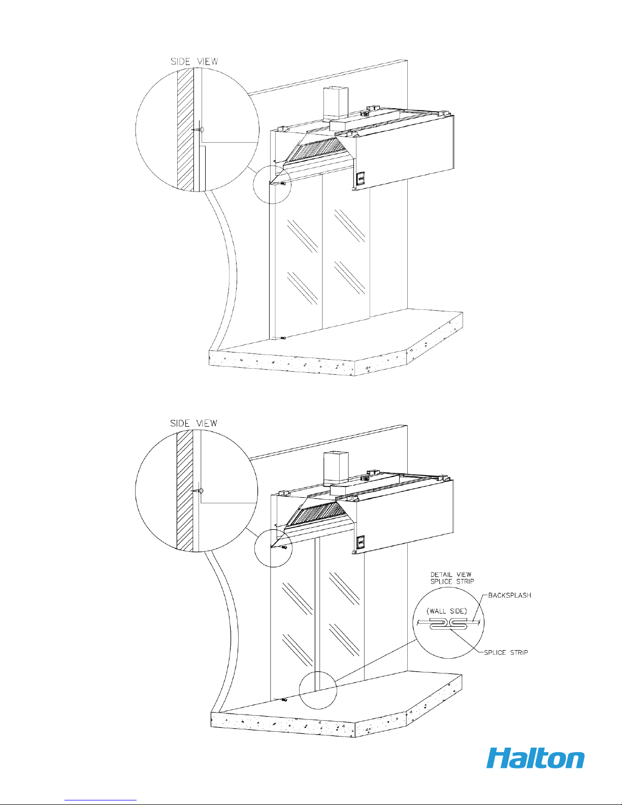
Screw through top of
flange to wall.
*( screw head will not
interfere with hood)
Screw backsplash to
wall or attach with
adhesive.
1” Insulated Backsplash Assembly
Halton canopy hoods
should be installed
from 78” min.- 84”
max. above the
finished floor.
Flat Sheet Backsplash Assembly
Capture Jet® Operation & Maintenance Manual
5
OM-005/052017/rev3/EN
Page 6

Typical Hood Installation Details
*Optional Unistrut / Turn Buckle
Detail
Hanger Bracket / Turn
Buckle Detail -
Welded to top of hood.
18 ga. material All Thread
(By Others)
Hang the hood using 1/2” threaded rods by attaching the rods to the hood through the hanger brackets (as shown)
which are fastened to the top of the hood, using the turnbuckles will make final adjustments easier. Hanging height
of Canopy hoods should be per local building codes, verify with “Authority Having Jurisdiction” for hanging height in
your project location.
Standard hanging height is 78” minimum to 84” maximum above the finished floor.
Capture Jet® Operation & Maintenance Manual
6
OM-005/052017/rev3/EN
Page 7
Recommended Exhaust Duct
Installation Details
6
Exhaust
Duct Options Available
Supply Duct
Exhaust Duct
per code
Supply
Duct
Supply Duct may be attached to supply collar with sheet
metal screws or pop rivets and sealed with duct tape.
Screws or Rivets are not to interfere with the operation of
the fire damper (if equipped).
Capture Jet® Operation & Maintenance Manual
7
OM-005/052017/rev3/EN
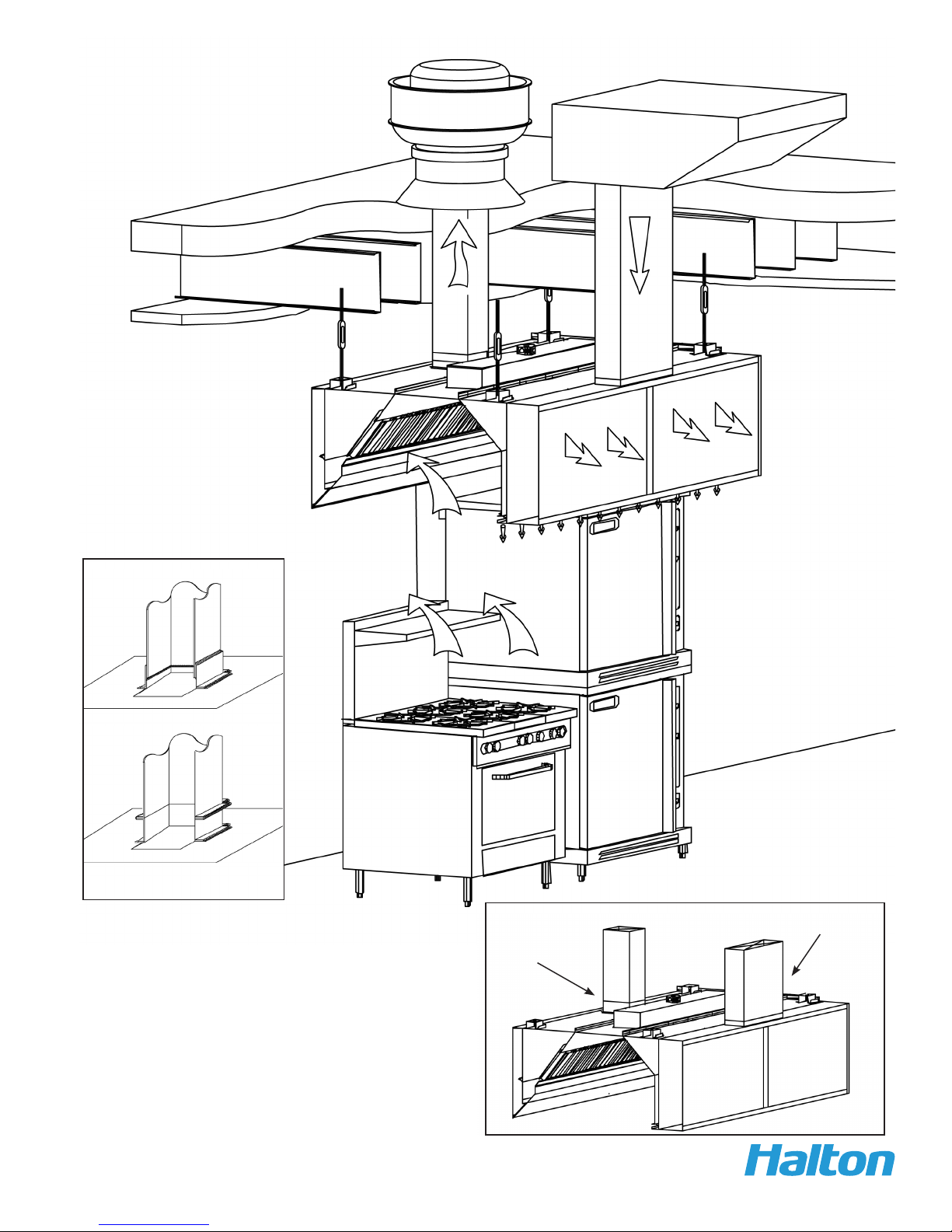
Page 8

Splice Strip / U-Channel Assemblies
Fig. 1
A
U-Channel
Installation Notes:
U-Channel:
For hood models that are placed back to back (as shown in Fig. 1):
Slide the U-Channel A up over the back of the hood systems, and secure
with sheet metal screws.
For hood models that are placed end to end (as shown in Fig. 2):
Pry apart the U-Channel at one end and slide over the end panels,
Hoods shown back to back
A
fastening in place where the end to end hood’s side panels meet.
Splice Strip:
For hoods placed end to end: Slide over bottom front edge first then over top,
secure by welding together, or as an option using screws for models with
supply plenum.
Hoods shown end to end
Fig. 2
B
A
B
Splice Strip
U-Channel
A
Capture Jet® Operation & Maintenance Manual
8
OM-005/052017/rev3/EN
Page 9

Closure Panel Assembly
C
C
B
8
D
E
B
A
Installation Notes:
1. Both panels labeled “B” are set on top of the hood at each end wall
*Vertical flange at the bottom of closure panel and vertical
flange on top of hood should line up.
2. Hammer clips “C” over the two vertical flanges.
3. Attach panels “B” to wall using appropriate hardware “D”
4. Slide front panel “A” into place.
5. Attach panels “B” to wall using appropriate hardware “D”. Be sure
closure panels are vertical and aligned with hood end walls.
*(Hardware not provided by Halton)
1.
E
D
B
B
A
C
C
Capture Jet® Operation & Maintenance Manual
9
OM-005/052017/rev3/EN
Page 10

Standard Capture Jet Hood Wiring
BLACK
POWER
SUPPLY
POWER
SUPPLY
GREY
WHITE
GREY
WHITE
WHITE
WHITE
WHITE
BLACK
WHITE
***ONE SUPPLY PER LIGHT***
GRD
YELLOW
YELLOW
WHITE YELLOW WHITE YELLOW
WHITE
YELLOW
JUMPER
RELAY BOX
TOP OF HOOD
BLACK
SWITCH PANEL
LIGHT CIRCUIT TO NEXT HOOD
BLACK
NC
NO
COM
RELAY
+
C
NO
-
BLACK
BLACK
WHITE
BLACK
N
L
NC
LIGHT SWITCH
H
FUSE
3A
R1-1
TR
N.O. ANSUL SWITCH
FIELD INSTALLED
(NIGHT CIRCUIT)
11 12
TR-1
R2-1
5
6
BLACK SWITCHED (LIGHT)
BLACK SWITCHED (FAN)
WHITE
BLACK SUPPLY
BLACK
BLACK
NC
NO
RELAY
COM
L
+
BLACK
C
NO
NC
-
FAN SWITCH
120/1/60
1 2
15 MIN DELAY
OFF TIMER
GROUND
WHITE
N
TEMP SENSORS
N.C. ANSUL SWITCH
FIELD INSTALLED
MUA
9 10C
3 4
C
R
120V TO EXHAUST FAN COIL
OR RELAY TO PROVIDE
CONTACT CLOSURE FOR 24V
STARTER COIL OR BAS/BMS
SIGNALS
BLACK
R1
LED HOOD LIGHTS
RED
SPEED
CONTROLLER
N
G
GROUND
R2 WHICH WILL START THE
(UNATTENDED) OPERATION:
MICROSWITCH WILL CLOSE
EXHAUST FAN. (THE N.C.
MICROSWITCH ON THE MUA
PREVENTING THE MUA FAN
GREEN
WHITE
CAP. CONN.
GREEN
MAY BE WIRE
NUT OR SPADE
CAPACITOR
RED
120V, SWITCHED
7
ADDITIONAL RELAY NOTE
THE USE OF R2 IS
OPTIONAL. 120 VOLTS
ACROSS R2 COIL
CONTACTS WILL ACTUATE
FAN CIRCUIT. IT CAN BE
USED WITH A REMOTE
SWITCH OR OTHER
ACCESSORY TO START THE
NIGHT CIRCUIT
IF FIRE SUPPRESSION
SYSTEM FIRES THE N.O
AND TURN ON THE
CIRCUIT WILL OPEN
FROM OPERATING)
BLACK
TAN
CAPTURE JET
BLOWER MOTOR
120/1/60
.72 AMPS
R2
120V
FAN.
GR AY
GREEN/YELLOW
BY HALTON
BY ELECTRICIAN
8
TIMER PANEL
TEMP SENSOR OPERATION:
WHEN ENOUGH HEAT (95°F) TO ACTIVATE SENSOR IS PRESENT, EX FAN AND MUA
FAN WILL START AND WILL REMAIN ON FOR 15 MIN AFTER HEAT SENSOR DEACTIVATES. FAN SWITCH CAN OVERRIDE HEAT SENSOR "ON" FUNCTION AT ANY TIME.
FANS WILL REMAIN ON FOR 15 MIN AFTER EXHAUST FAN SWITCH IS TURNED "OFF".
Capture Jet® Operation & Maintenance Manual
10
OM-005/052017/rev3/EN
Page 11

Hood Wiring Details
The Halton hood is equipped with a Timer Panel which fulfils the International Mechanical Code required interlock
which will turn on the exhaust fan serving the hood if an appliance is turned on without also turning on the fan. This is
accomplished with a temperature sensor in the hood that senses elevated temperature in the hood. This temperature
sensor closes a circuit at 95 degrees Fahrenheit which turns on the exhaust fan. All hoods which are ducted to the same
exhaust fan must have their temperature sensors wired in parallel with the sensor on the hood with the Timer Panel.
This hood is typically the same hood that has the lights and/or fan switch. This required interlock circuit is not intended
to act as the primary means of turning on the exhaust fan. The exhaust fan will always remain on for 15 minutes after
the temperature sensor has cooled lower than 95 degrees Fahrenheit, even if the fan switch has been turned off. This
allows a cool down period for the appliance and removal of heat in the space protected by the hood. The timer panel also
has provision for a night circuit which can turn on the exhaust fan if the fire suppression system fires when the kitchen
is unattended and the hood is off. This circuit is wired through one of the micro switches in the fire suppression control
cabinet. Provision is also made for a Make Up Air interlock which can start the Make Up Air fan whenever the exhaust
fan is operating. This circuit is typically wired through one of the micro switches in the fire suppression control cabinet in
order to turn off the Make Up Air during a fire event. Please see the wiring diagram for details about these options.
The Capture Jet fan will typically remain on in Fire Mode to assist with capture and containment of produced smoke. The
Halton Capture Jet hoods are tested and listed to allow the Capture Jet fan to remain on.
Field Connection of Hood Power
Incoming 120 volt power for the hood lights and the Capture Jet fan is connected to terminals in the Timer Panel on top of
the hood.
When hoods are arranged end to end or back to back one switch panel often controls all of the lights in the hood group.
The electrical power will then be field connected from the hood with the incoming power, the hood with the switch panel
and/or timer panel, to the other hoods in the hood group. Remove the cover from the junction box next to the Capture
Jet intake, on top of the hood. Remove wire nuts from green, white and the switched black for the light circuit and add
field wiring to the same wire junctions on the next hood. Not all hoods may have a timer panel or LED lights. Please
refer to the specific job submittal drawings for wiring diagrams customized to the product mix and arrangement of each
jobsite. Submittal drawings supersede the general wiring diagram found in this manual.
Capture Jet® Operation & Maintenance Manual
11
OM-005/052017/rev3/EN
Page 12
Capture Jet® Fan Installation
Integrated Capture Jet ® fan
(Standard)
KSA Filter
T.A.B. Ports
Speed
Controller
Models KVE, KVC, KVR, KVW and KCH are
equipped with an Integrated Capture Jet® fan
package, as shown above.
This style is standard for Model KVL
Capture Jet
Fan
Top of Hood
®
Capture Jet
Plenum
Front of
Hood
®
(Optional)
J BOX
SPEED
CONTROLLER
J BOX
Typical Wiring of External
Capture Jet® Fan
BY HALTON
FIELD WIRING
CAPACITOR
BLACK
GREEN/LT GREEN
BROWN
RED
RED
BLUE
BLACK
GREEN
WHITE
CAPTURE JET
BLOWER MOTOR
120/60/1
1.3 AMPS
BLACK
GREEN
WHITE
5 AMP Speed Controller wired on
top of hood or located in the Control
Panel
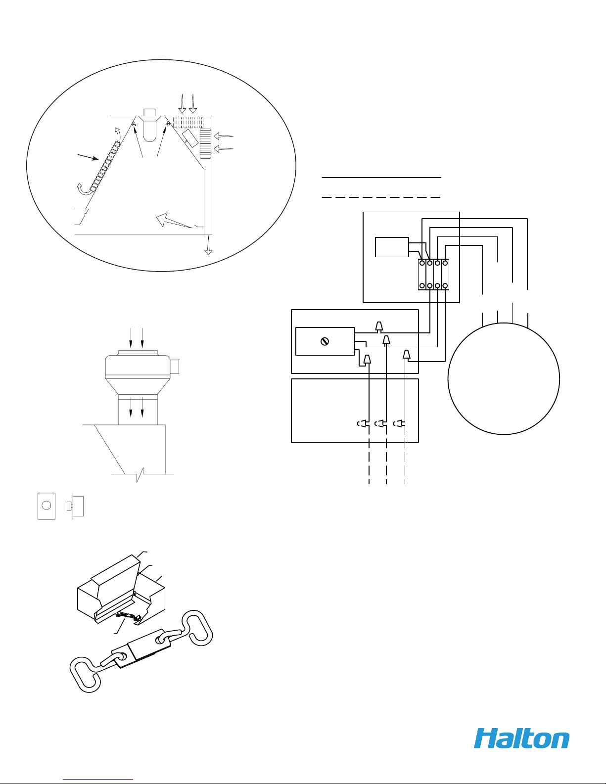
CUTAWAY VIEW OF COLLAR
DAMPER
DAMPER STOP
COLLAR
FUSIBLE LINK
74° C (165° F)
FUSIBLE LINK ASSEMBLY
DETAIL
1. OPEN DAMPER TO DAMPER STOP
2. HOOK ONE END OF FUSIBLE LINK TO HOOK ON DAMPER
3. HOOK OTHER END OF FUSIBLE LINK TO HOOK ON COLLAR
Capture Jet® Operation & Maintenance Manual
120 V HOT
GROUND
NEUTRAL
120/1/60
INCOMING CIRCUIT
The KVL external Capture Jet fan has a fire damper in the collar that
must be set to open before the fan is attached to the collar. Open
the damper blade until it is against the damper stop. Hook one end
of the fusible link to the hook on the damper. Hook the other end of
the fusible link to the hook on the collar. If attaching the Capture Jet
fan to the intake collar with sheet metal screws be certain that the
screws do not interfere with the action of the damper.
12
OM-005/052017/rev3/EN
Page 13

Capture Jet® Fan Adjustment
The Halton Capture Jet fan is factory set and should not need adjustment. If adjustment is necessary it may be
adjusted for air flow output. Before any adjustment measure the static pressure produced by the Capture Jet fan at the
Capture Jet plenum TAB (Testing And Balancing) port. The static pressure should measure 0.25” (0.29” for the KVL) of
positive water column (plus or minus 0.02”) If adjustment is necessary it may be easily accomplished by following the
instructions below.
1. Locate the Capture Jet fan access cover. This is an approximately 12” square plate on the inside front face of the
hood. The access cover will have a small removable button cap in its center. External Capture Jet fans will have the
speed control in a 2” x 4” standard J-box located very near the fan.
2. Remove the button cap by prying it up gently with a fingernail or edge of a credit card, or similar object. Notice that
under the button cap is an adjustment screw. The adjustment screw allows control of the fan and thus the amount of
airflow from the Capture Jets.
3. The Capture Jet fan should be adjusted to produce 0.25” of positive water column pressure as measured at the
Capture Jet plenum TAB (Testing And Balancing) port. Very small adjustments of the speed control screw will result
in measurable changes to the static pressure. Allow the pressure to stabilize between adjustments. For optimum
accuracy replace the button cap or block the opening while the pressure is stabilizing.
4. Use a small screwdriver to rotate the adjustment screw. Usually very little adjustment is necessary. Read the
following before making any adjustment. This is for reference only; you will not need to use the full range of the
speed control in normal circumstances. Turning the adjustment screw as far as possible counterclockwise will result
in a distinctive “click” which will turn the Capture Jet OFF. Turning the screw clockwise from the OFF position will
adjust the fan speed from Maximum to Minimum. The fan will be at maximum speed immediately after the click that
turns the fan on, turning clockwise from the OFF position. Further adjustment in the clockwise direction reduces the
fan speed.
Capture Jet® Operation & Maintenance Manual
13
OM-005/052017/rev3/EN
Page 14

T.A.B.™ - Testing and Balancing Ports
**** It is very important the cooking equipment is in operation to create a thermal plume, prior to the air balancer,
to be able to use the T.A.B. ports.
****For accurate results, the balance contractor should receive a copy of the job specific hood plans with the design T.A.B. readings from the hood supplier prior to balancing.
Capture Jet® Operation & Maintenance Manual
14
Closeup view
of T.A.B. Port
OM-005/052017/rev3/EN
Page 15

KSA Filter Removal with Model KFR
It is Important that the top lip and
bottom lip of the lter are hooked
correctly
Insert KFR tool
Slide lter up Push lter back and down Lift lter out of plenum
Tilt top of lter out
Lift lter into plenum Push lter in and down
Tilt top of lter in
Lift lter to the front
Slide lter down
Remove KFR tool
16 ga. S.S. Bracket
S.S. Coupling
S.S. Pipe
To assemble the KFR filter remover:
Screw together stainless steel pipe, coupling, and bracket and tighten all joints. (as shown in above picture)
Filter Installation and Removal
To remove filter:
Insert bracket into the inside KSA
filter slots, and lift upward until
filter slides out of plenum.
To install filter:
Place filter on KFR (filter removal
tool) bracket, raise filter into place
inside exhaust plenum. Slide upward until top lip of filter is locked
into place and bottom lip of filter
slides in place inside the exhaust
plenum.
*** It is very Important to lock
top lip of filter in place in installation as shown in reference
drawing.
Capture Jet® Operation & Maintenance Manual
15
OM-005/052017/rev3/EN
Page 16
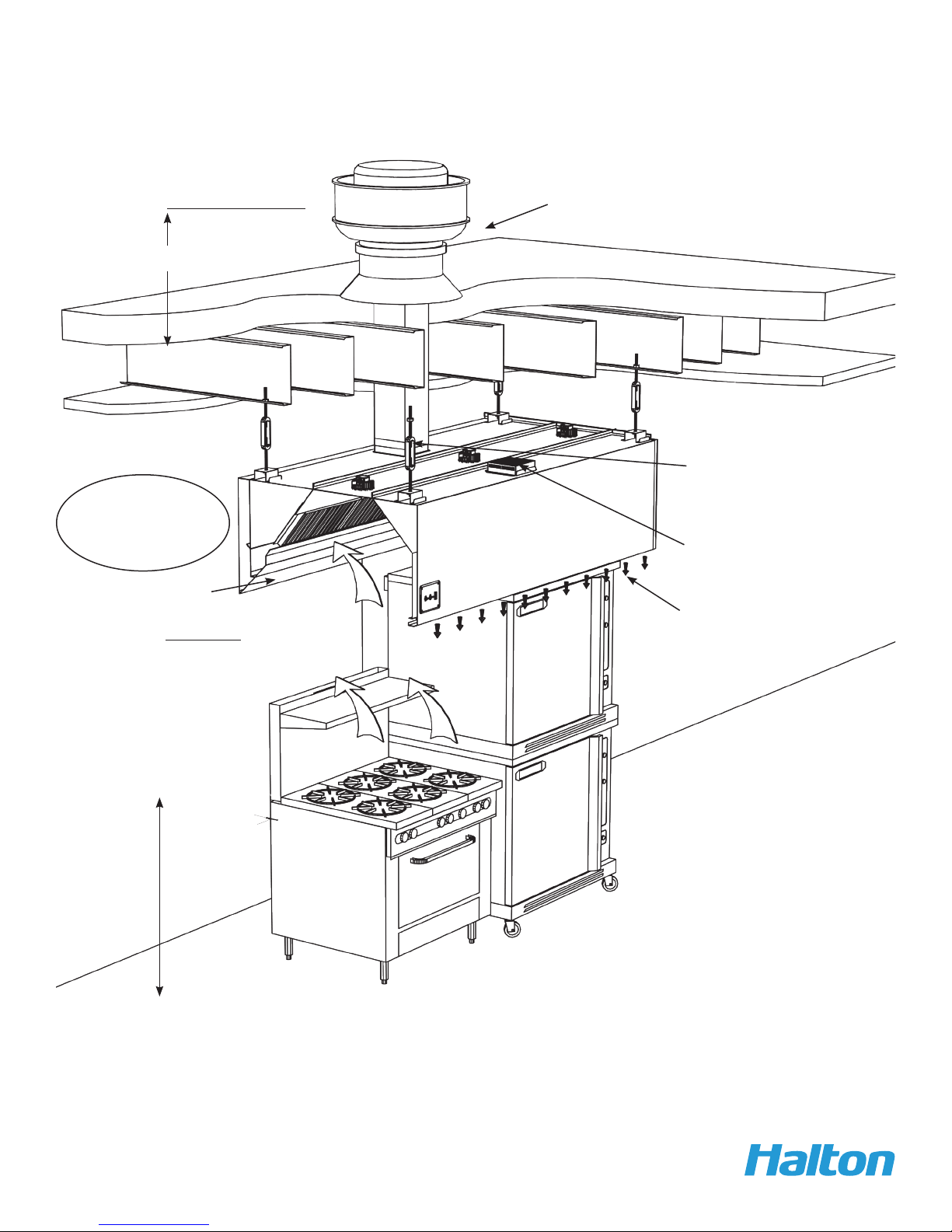
Model KVE Typical Installation
40 “ min.
**Incandescent or
Fluorescent lighting
available.
UL listed upblast fan for restaurant
cooking appliances
16 ga. duct work all
welded per code
Standard top mounted
Capture Jet® intake)
KSA Filters
78”-84” A.F.F.
Standard
**(Verify with Authority
in project location for
min. hanging height)
Capture Jet
Airow
Capture Jet® Operation & Maintenance Manual
16
OM-005/052017/rev3/EN
Page 17

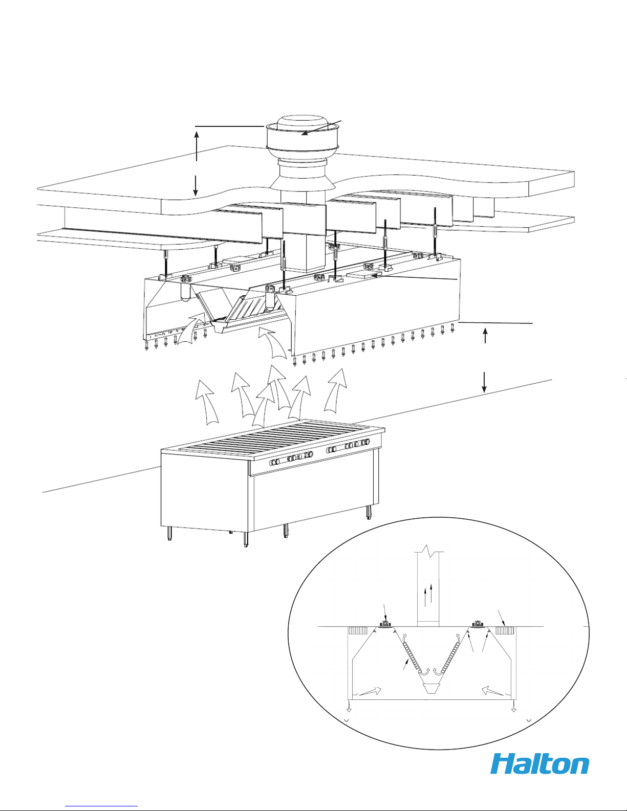
Model KVC Typical Installation
40” min.
120” min.
Filtered MUA
unit on the
roof
16 ga. duct work all
welded per code
Stainless
Steel KSA
lters
78” - 84” A.F.F.
78” Std.
**(Verify with Authority
in project location for
min. hanging height)
Make-up airow
Capture Jet® air
Capture Jet® Operation & Maintenance Manual
17
OM-005/052017/rev3/EN
Page 18
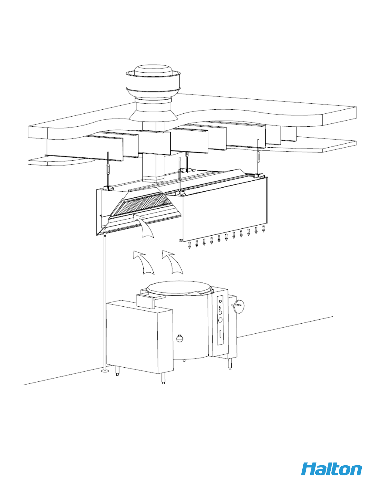
Model KVW Typical Installation
See page (22) for supply options
40” min.
UL listed upblast fan for restaurant
cooking appliances
Integrated Capture Jet®
location
78” - 84” A.F.F.
(78” Std.)
**(Verify with Authority in project
location for min. hanging height)
Side view of typical install
Exhaust Air
LED
lights
Integrated
Capture Jet® fan
Drop
Ceiling
Capture Jet® Operation & Maintenance Manual
18
S.S. KSA
Filters
T.A.B.
Ports
Capture Jet® Air
OM-005/052017/rev3/EN
Page 19

Model KVW Typical Installation
LED lighting
KSA lters
Exhaust Air
(W/ 1 Perf Plenum)
Capture Jet®
fan
T.A.B. Ports
Capture Jet® Air
Supply Air
Drop
Ceiling
S.S. Perf
(Low Velocity)
Supply Air
LED lighting
KSA Filters
Exhaust Air
(W / 2 Perf Plenum)
Supply Air
Capture Jet® fan
T.A.B. Ports
Capture Jet® Air
S.S. Perf
(Low Velocity)
Capture Jet® Operation & Maintenance Manual
19
OM-005/052017/rev3/EN
Page 20

Model KVL Typical Installation
40” min.
UL listed upblast fan
for restaurant cooking
appliances
16 ga. duct work all
welded per code
Capture Jet® fan
Stainless
Steel KSA
lters
Capture Jet® air
**(Verify with Authority in
project location for min.
hanging height)
58” -64” A.F.F.
Capture Jet® Operation & Maintenance Manual
20
OM-005/052017/rev3/EN
Page 21

Model KVM Typical Installation
40” min.
Capture Jet® fan
UL listed upblast fan
for restaurant cooking
appliances
16 ga. duct work all
welded per code
Stainless
Steel KSA
lters
Rear Seal
Capture Jet® Operation & Maintenance Manual
21
OM-005/052017/rev3/EN
Page 22

Model KVM Side Skirt Installation
1. Panels “A” are placed at the outside ends of the hood at each end of the hood group.
2. Align the weld studs on the upper edges of the side skirts with the holes in the lower edge of hood ends and
hang the panels on the ends of the hood group.
3. Fasten panels “A” to the ends of the hood with hardware “B”
Capture Jet® Operation & Maintenance Manual
22
OM-005/052017/rev3/EN
Page 23

Model KVO & KVR Oval and Round Hood Systems
3D Plan view of round KVR
Model KVR Round and Oval hoods can be shipped in pieces for field assembly. If pieces are
shipped loose, parts will be marked for easy assembly, and an Operation and Installation, and
Maintenance manual will be provided.
45º min
lter angle
3D Plan view of oval KVR
minimum
height
24”
Capture Jet® Operation & Maintenance Manual
Cross section of KVR
23
OM-005/052017/rev3/EN
Page 24
Model KCH Typical Installation
Capture Jet® Operation & Maintenance Manual
24
OM-005/052017/rev3/EN
Page 25

WARRANTY ACTIVATION FORM
This form must be completed and returned to Halton in order for your warranty to be valid.
Job & Location Information:
Job Name:
Street Name:
City: State:
Zip Code:
Equipment Start-Up Date: Product Serial Numbers:
Contact Information:
Contact Name:
Title:
Chef, Kitchen Mgr/Facility Mgr/Property Mgr/etc.
Facility Management Company Name (if applicable):
Email:
Phone Number: Cell Number:
Fax completed form to:
Halton Company
Attention: Service Department
Fax: (270) 237-5700
Halton Indoor Climate Systems
Attention: Service Department
Fax: (905) 624-5547
Warrant Activation Form
OM-005/052017/rev3/EN
Page 26

HALTON LIMITED WARRANTY
Halton (“Manufacturer”). Warrants only to its direct purchasers and to no others, that all products
manufactured by the Manufacturer shall be free from defect in materials and workmanship for a period
of twelve (12) months from the date of the original installation and start-up or eighteen (18) months from
date of shipment, whichever occurs first. All products sold but not manufactured by Manufacturer will
be warranted for a period of twelve (12) months from date of shipment. (Halton’s Warranty Card must be
completely filled out and returned to Halton within 3 weeks after the equipment start-up date for your
warranty to be valid *IMPORTANT NOTE: “IF” this form is returned within the specified time frame,
Halton will extend your standard warranty by 120 days.)
For products manufactured by the Manufacturer we agree to pay any reasonable labor costs necessary to
repair or replace, at Manufacturers option, defective parts or materials for a period of twelve (12) months
from date of original installation and start-up or eighteen (18) months from date of shipment, whichever
occurs first. All labor costs subject hereto shall be performed during standard work hours at straight-time
rates.
For products sold but not manufactured by the Manufacturer we agree to pay any reasonable labor costs
necessary to repair or replace, at Manufacturers option, defective parts or materials for a period of (90)
days from date of original installation and start-up or (12) months from date of shipment, whichever occurs
first. All labor costs subject hereto shall be performed during standard work hours at straight time rates.
All warranty claims that include labor requires pre-approval by Halton. Halton, at its discretion, will
authorize field warranty work through its own service network or certified third party. No claims for labor
charges will be approved for payment if work commences without prior authorization by Halton.
Purchaser shall pay incurred premium labor charge, including overtime, weekends and holidays. Travel time,
service charges, miscellaneous tools, material charges, and labor charges resulting from inaccessibility of
equipment will not be paid by Manufacturer.
This LIMITED WARRANTY SHALL APPLY ONLY to products that have been installed and maintained in
accordance with the installation and Care Instruction Manuals. Purchaser shall be solely responsible for
adhering to the instructions and procedures set forth in the said instruction manuals.
This LIMITED WARRANTY SHALL NOT BE APPLICABLE to any damage or defect resulting from fire,
flood, freezing or any Act of God, abuse, misuse, accident, neglect or failure to adhere to all instructions
set forth in the installation and Care Instruction Manuals. Furthermore, this limited warranty shall not
apply to any product that has been altered, unless such alteration has been approved in writing by a duly
authorized representative of the manufacturer. In no event shall the manufacturer be liable for any loss,
expense, personal injury or consequential damage, of any kind or character, as may result from a defect
in material, and/or workmanship, however caused.
EXCEPT AS IS EXPRESSLY SET FORTH IN THIS LIMITED WARRANTY, MANUFACTURER MAKES NO
WARRANTY OF MARKETABILITY FOR FITNESS OR ANY PARTICULAR PURPOSE. NEITHER DOES
MANUFACTURER MAKE ANY WARRANTY, EXPRESSED OR IMPLIED, WITH RESPECT TO PRODUCTS
SOLD BY MANUFACTURER OR AS TO THE USE THEREOF.
Continuous product improvement is a Halton policy, therefore specifications and design are subject to change without notice.
Halton Company
101 Industrial Drive, Scottsville, KY 42164, USA
Phone 270 237 5600 | Fax 270 237 5700
Website: www.halton.com
OM-005/052017/rev3/EN
Halton Indoor Climate Systems, Ltd.
1021 Brevik Place, Mississauga, ON L4W 3R7, Canada
Phone 905 624 0301 | Fax 905 624 0301
 Loading...