

Page 1

S3 and S4 Hall Effect Sensor
Installation and Setup Procedure
Page 2

E.2.3 Hall Effect Sensors
The Haltech hall effect sensor is a two channel device that can be used to trigger the
Haltech range of ECU’s in a wide range of applications.
The most common application is in a direct fire configuration where a synchronisation
event is required. As the Haltech hall effect sensor is dual channel, it can provide this
synchronisation pulse as well as the trigger signal.
The principle behind its operation is quite simple. As a magnet passes the sensor the
output state changes fro m high to low. The orientation of the magnets determines the
output signals from the sensor.
There are two types of hall effect sensors available from Haltech
The S3 Hall Effect Sensor
The S3 sensor which is identified by a black cable gland, operates i n the following
way:
As a south pole passes the sensor face the signal in both the primary (PIN C) and
secondary (PIN D) channels are switched to a low state. As a north pole passes the
sensor a low state will only occur on the primary channel.
Note: magnets should always be mounted in a non ferrous material
such as aluminium, stainless steel or titanium.
Many installers have successfully mounted the rare earth magnets in non -ferrous
surrounds such as modified aluminium and stainless steel bolts, and ins talled the bolts
into ferrous material.
With these characteristics a direct fire can be set up in the following way:
Using the sensor on the crank
After a suitable mounting location for the sensor has been found the engine should be
positioned at approx imately 75° BTDC on cylinder no.1 compression. The magnet
should now be placed in the aluminium disk with the south pole facing towards the
sensor, making sure the magnet is in line with the sensor when the engine is in this
position. This is now the refer ence point for all the other magnets. The number of
cylinders will determine the number of magnets required and the angle of installation.
The remainder of the magnets to be fitted will all have a north pole facing the sensor.
The adjustment of the air ga p will be determined by the strength of the magnets used.
This should be tested once the wheel assembly has been installed. Checking the
Engine Data page for steady RPM is usually a good indication that the airgap is
acceptable.
Page 3

Identifying the magnets poles
If you need to identify the magnet poles this can be done easily with the use of a
multimeter. By powering up the sensor, using 12 volts (PIN B) and ground (PIN A)
the secondary trigger channel (PIN D) can be checked to identify a south pole.
Connecting the multimeter between PIN D and ground, 12 volts should be present.
When a South pole is placed in front of the sensor this value will go to 0 volts.
Fitting the magnets
We insist that only Haltech rare earth magnets (part number REM1) be used for the
purpose of triggering the sensor. Rare earth magnets purchased from your local
electronics store may be less expensive but they are not good enough! Haltech rare
earth magnets are strong with good stability to reasonably high temperatures and
which have a long service life. Some rare earth magnets are stronger but break down
under excessive temperature, or are too brittle for the purpose, or do not have a long
service life. Ordinary magnets ie not rare earth types, may not have the strength
required for satisfactory triggering at high speeds.
Haltech REM1 rare earth magnets are normally 5mm dia x 2mm depth, although other
sizes are available upon special order.
The magnets should be fitted in non -ferrous surrounds such as aluminium, stainless
steel or titanium. The trigger wheel is normally made of the chosen material but
various users have reported good results when the magnets are set in a suitable non ferrous surround and the surround is set into a ferrous material.
The magnets should be set flush w ith or slightly back from the surface of the trigger
wheel or surround. If set too far back the magnetic signal may be too weak. The
magnets should be set in place with a strong and durable fixing compound such as
high strength epoxy, Loctite stud locking compound eg 603, or JBweld. Some users
rely only on the fixing compound but to ensure that the magnets remain in place but
many prefer that they be retained by mechanical means such as peening, and this
gives an added safety factor.
WARNING:
RARE EARTH MAGNETS ARE EASILY DAM AGED AND THE
PEENING PROCESS (OR LOCATION BY GRUB SCR EWS
ETC) SHOULD BE VERY CAREFULLY CARRIED OUT SO AS
NOT TO DAMAGE THE MA
WILL NOT HAVE SUFFIC IENT MAGNETIC STRENG
MAY FAIL MAGNETICALL Y OR PHYSICALLY AFTER A
PERIOD OF TIME.
If installed correctly the magnets will have a long life.
GNETS. IF DAMAGED THEY
TH OR
Page 4

Note: In the following examples, for ease of reference, the magnets are
shown mounted on the circumference of a wheel with the Haltech Hall
effect sensor oriented to one side. If so mounted the magnets need to
be mounted with sufficient strength to resist centrifugal force. In
practice the magnets are often mounted within the circumference of the
wheel and the sensor is mounted so that its base is pointed towards the
magnets in the face of the wheel.
Typical set -ups - S3
4 cylinder / 2 rotor engine
For a four cylinder 2 magnets are required in total, positioned exactly 180° apart.
Figure 1: Typical 4 cylinder/ 2 rotor application
6 Cylinder / 3 Rotor Engine
For a six cylinder 3 magnets are required in total, positioned exactly 120° apart.
Figure 2: Typical 6 cylinder/ 3 rotor application
Page 5

8 Cylinder
For an eight cylinder 4 magnets are required in total, positioned exactly 90° apart.
Figure 3: Typical 8 cylinder application
The ignition set-up for the S3 needs to be configured in the following way:
Trigger Edge: Rising
Trigger type: Standard
Home Edge: Falling
Page 6

The S4 Hall Effect Sensor
The S4 sensor which is identified by a grey cable gland operates in the following
way:
As a south pole passes the sensor face the signal in the secondary (PIN D) channel is
switched to a low state. As a north pole passes the sensor a low state will only occur
on the primary channel (PIN C).
The set-up for this sensor is similar to the S3 except that one extra magnet is required
as well as the orientation being changed. The north pole of the magnet is used to
generate the main trigger while a south pole is used to generate the home or
synchronisation pulse.
Typical set -ups - S4
4 cylinder / 2 rotor engine
For a four cylinder 3 magnets are required in total. Two north poles positioned exactly
180° apart while a south pole needs to trigger the sensor before the trigger for
cylinder No 1. Th e positioning of the magnet for cylinder one is done the same way
as the for the S3 making sure the north pole is triggering the sensor at approximately
75° BTDC.
FIGURE 4: TYPICAL 4 CYLINDER/ 2 ROTOR APPLICATION
Page 7

6 CYLINDER / 3 ROTOR ENGINE
For a six cylinder 4 magnets are required in total. The three north poles are positioned
exactly 120° apart while a south pole need to trigger the sensor before the trigger for
cylinder No 1.
Figure 5: Typical 6 cylinder/ 3 rotor application
8 Cylinder
For an eight cylinder 5 magnets are required in total positioned exactly 90 ° apart. A
south pole needs to trigger the sensor before the trigger for cylinder No 1.
Figure 6: Typical 8 cylinder application
The ignition set-up for the S4 needs to be configured in the following way:
Trigger Edge: Falling
Trigger type: Standard
Home Edge: Falling or Rising
Page 8
E.3 Synchronisation Events
Synchronisation Events (Sync Events) are required for sequential and direct fire
systems. The Sync Event gives the ECU in indication of the engines position. The
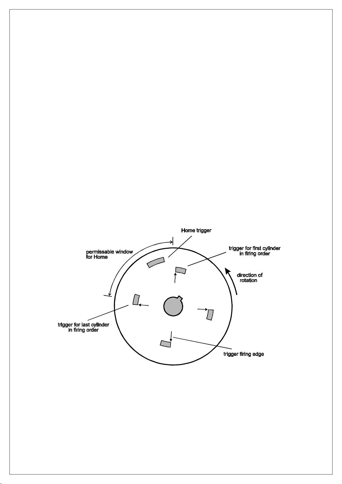
most common form of Sync Event is a Home Trigger. Other Sync Events a re the
missing teeth on multitooth triggers. A Home Trigger is usually a separate trigger
from the main trigger, but some special trigger sensors, such as the Haltech Hall
Effect Sensor, can generate both signals from the one sensor.
For a direct fire sys tem the home trigger tells the ECU that the next trigger is for coil
one (which is usually connected to cylinder one). The ECU then cycles through its
ignition outputs until it expects a Home trigger again. If it receives a Home it will
cycle again. If it does not receive a Home before the next trigger, it will not output a
spark until the Home is received.
Home triggers for the E6K do not need to be accurately timed. All it does is tell the
ECU that the next main trigger is significant. Usually, but not n ecessarily, the
significance is that the next main trigger is for cylinder one. Therefore, the Home
trigger must occur before the main trigger for cylinder one and after the main trigger
preceding the cylinder one trigger. (See Figure 6). The Home trigger should not occur
at the same time as any other trigger. Check that the trigger and Home Edges are set
correctly.
Figure 6. Home Trigger position on a cam angle sensor for 4 cylinder with a home trigger
occurring every cam revolution.
Page 9

PIN
+13.8VDC SWITCHED
1
HOME
2
TRIGGER
3
GROUND
4
CONNECT TO
HALTECH S3 / S4 HALL EFFECT SENSOR
HALTECH S3 / S4 HALL EFFECT SENSOR
4 PIN CONNECTOR
4 PIN CONNECTOR
Looking into connector
1 2 3 4
FEED WIRE THROUGH BOOT,
CRIMP PIN TO WIRE AND THEN INSERT INTO BACK OF PLUG, PUSH UP LOCKING TAB
CRIMP PIN TO WIRE AND THEN INSERT INTO BACK OF PLUG, PUSH UP LOCKING TAB
FEED WIRE THROUGH BOOT,
TRIGGER INPUT:
TRIGGER EDGE:
HALL EFFECT
RISING
HOME INPUT:
HOME EDGE:
HALL EFFECT
FALLING
S3 SENSOR S4 SENSOR
BLACK GLAND
22331144
Looking Into Connector Looking Into Connector
22331144
HALTECH S3 / S4 HALL EFFECT SENSORHALTECH S3 / S4 HALL EFFECT SENSOR
TRIGGER INPUT:
TRIGGER EDGE:
GREY GLAND
HALL EFFECT
RISING / FALLING
S3 / S4 HALL SENSOR TERMINATIONS
HALTECH, SYDNEY AUSTRALIA
DATE: 16TH MARCH 2009
SHEET 1 OF 1REV C
TRIGGER INPUT:
TRIGGER EDGE:
DEF
A B C
LOOKING IN PIN
SIDE OF PLUG
COLOUR
PIN
A
BLUE
B
YELLOW
C
D
E
GREEN
F
RED
HALL EFFECT
RISING
S3 SENSOR S4 SENSOR
BLACK GLAND
CONNECT TO
GROUND
TRIGGER
N/C
N/C
HOME
+13.8VDC INJ
HOME INPUT:
HOME EDGE:
HALL EFFECT
FALLING
D
AFBEC
Looking into Front Of Connector
FEED SEALING RING ONTO WIRE,
CRIMP PIN AND SEAL TO WIRE AND THEN INSERT INTO BACK OF PLUG
CRIMP PIN AND SEAL TO WIRE AND THEN INSERT INTO BACK OF PLUG
FEED SEALING RING ONTO WIRE,
TRIGGER INPUT:
TRIGGER EDGE:
DEF
C
A B
LOOKING IN PIN
SIDE OF PLUG
HALL EFFECT
RISING / FALLING
GREY GLAND
S3 / S4 HALL SENSOR TERMINATIONS
HALTECH, SYDNEY AUSTRALIA
DATE: 31ST OCTOBER 2008
SHEET 1 OF 1REV A
 Loading...