

Page 1
RA8 Instructions
Introduction
The RA8 is a new type of reluctor adaptor from Haltech that offers excellent noise
rejection, and the ability to piggy back to a factory ECU reluctor so a Haltech can be
triggered whilst maintaining factory ECU control of non-performance oriented items.
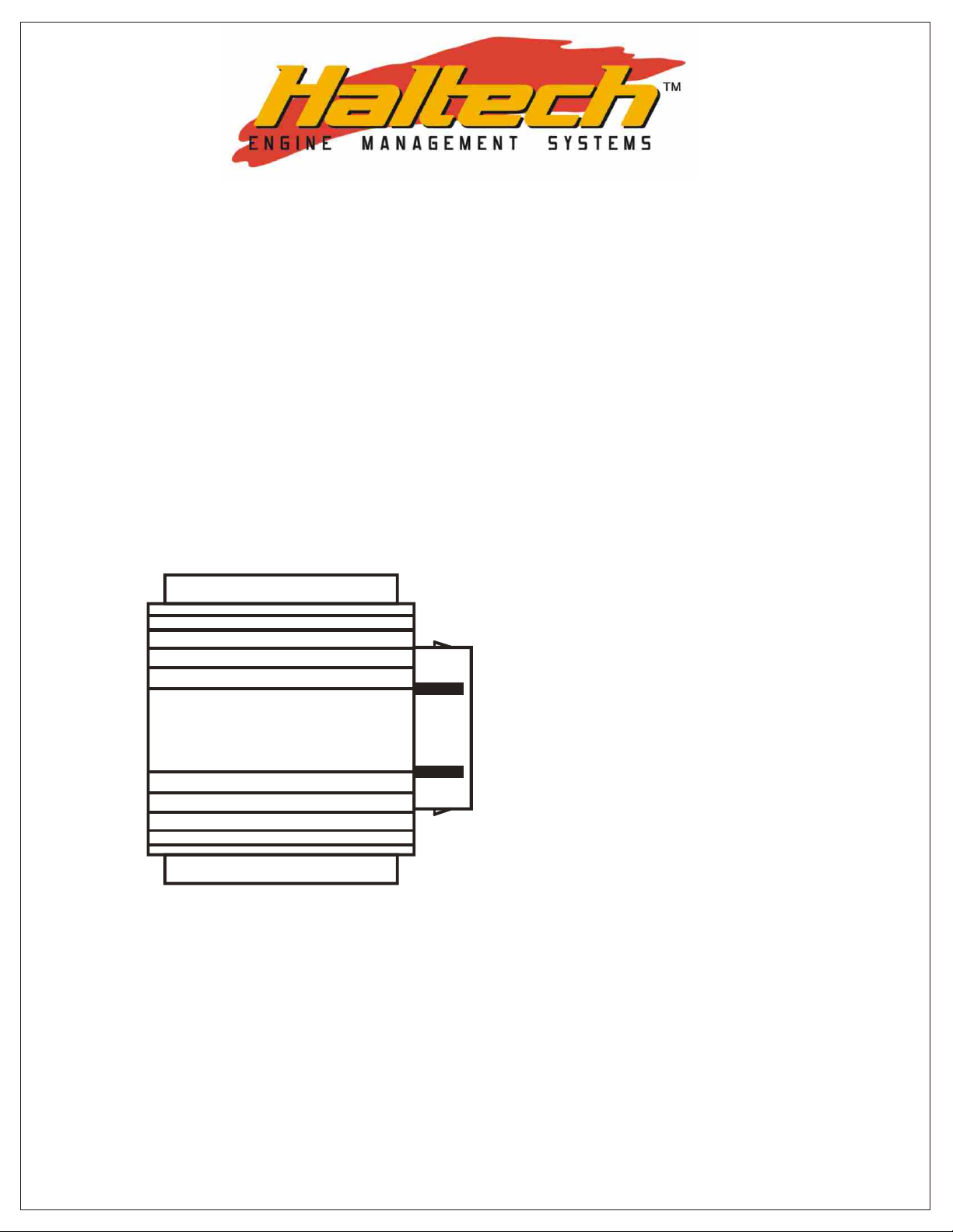
Pin-outs and Wiring
The RA8 has a 7-pin male connector attached to the extrusion, and a female receptacle
connector is supplied. The pin numbering of the connector is clearly marked on the
receptacle connector. Please ignore any numbering on the connector attached to the
extrusion.
1. CHANNEL B INPUT +VE
2. CHANNEL A INPUT +VE
3. CHANNEL A & B INPUT -VE
HALTECH
Generally channel A is used for the Trigger, and channel B for the Home, however the
channels are functionally identical.
Both reluctor coil negatives should be connected to the pin 3 reluctor input ground (or
just one if only one channel is being used). Connect the trigger coil positive to pin 2
Channel A In. Connect the home coil positive to pin 1 Channel B in. Connect a power
ground connection to pin 4, and a 12V supply to pin 5. Connect pin 7 Channel A Digital
Out to the Haltech trigger input, and pin 6 Channel B Digital Out to the Haltech home
input. Note that the Haltech should be set for normal input trigger, and not internal
reluctor adaptor, as the RA8 converts the reluctor signal to a normal trigger signal.
RA8
4. GROUND
5. +12V SWITCHED
6. CHANNEL B OUTPUT
7. CHANNEL A OUTPUT
Page 2

Setting RA8 DIP Switches
The DIP switches must be configured to suit the application. Access to the DIP switches
is achieved by removing the back plate of the extrusion (opposite side to the connector).
Of the 8 switches, the first 4 are for channel A, and the last 4 for channel B. The switches
are arranged so that switch 1 does the same for channel A as switch 5 does for channel B,
this is repeated for switches 2 and 6, 3 and 7, and 4 and 8. Each channel will have
identical settings if the switch settings are copied to the other channel.
The settings are summarized below:
Channel A
1. This switch is used to disable the RA8 to piggyback to an existing reluctor
connected to another ECU if the reluctor negative is biased to a voltage
other than 0V (Ground). It is recommended that this switch be ON to
disable this feature unless it is found that the existing ECU biases the coil
negative to a voltage other than 0V relative to battery ground. In this case,
the switch will decouple the RA8 from the ECU biasing so that it can
process the signal without affecting the existing ECU.
2,3,4. These switches set the gain as presented in the table below:
Switch 2 Switch 3 Switch 4 Gain
Off Off Off 1
On Off Off 2
Off On Off 3
On On Off 4
Off Off On 5
On Off On 6
Off On On 7
On On On 8
It is recommended that the minimum gain be used that gives a stable
signal (stable RPM). If in doubt please ring Haltech, and ideal settings
may be recorded for the trigger system being used.
Channel B
Same as above but swap switched 1,2,3,4 for 5,6,7,8.
Final Word
The RA8 has been tested on a number of applications, and has given excellent results.
However, please call Haltech if any problems are experienced.
2
 Loading...