

Page 1
PLATINUM SERIES
Haltech I/O Expander 12
HT059900
QUICK START GUIDE
Page 2

LIMITED WARRANTY
Lockin Pty Ltd trading as Haltech warrants the HaltechTM Programmable Fuel Injection System to be
free from defects in material or workmanship for a period of 12 months from the date of purchase.
Proof of purchase, in the form of a bill of sale or receipted invoice, which indicates that the product is
within the warranty period, must be presented to obtain warranty service. Lockin Pty Ltd trading as
Haltech suggests that the purchaser retain the dealer’s dated bill of sale as evidence of the date of
retail purchase.
If the HaltechTM Programmable Fuel Injection System is found to be defective as mentioned above, it
will be replaced or repaired if returned prepaid along with proof of purchase. This shall constitute the
sole liability of Lockin Pty Ltd trading as Haltech.
To the extent permitted by law, the foregoing is exclusive and in lieu of all other warranties or
representations, either expressed or implied, including any implied warranty of merchantability or
fitness. In no event shall Lockin Pty Ltd trading as Haltech, be liable for special or consequential
damages.
DISCLAIMER
Haltech will not be held responsible for any damage caused by the incorrect installation or tuning of this
product. It is the installers responsibility to ensure the wiring connections and pinouts match that of the
vehicle the unit is being installed into.
Haltech has taken all care to make sure the connections match the specified vehicles listed, but variations
in wiring and connections on vehicles can occur and therefore this should be checked BEFORE the unit
is installed.
Haltech highly recommends installation and tuning of this product is to be carried out by a professional,
with an understanding on installing and tuning engine management systems.
Misuse of this product can destroy your engine.
WARNING
This ECU is designed and sold for Racing use only. Using this product for street / road use may be
prohibited by law. Please check with your local vehicle authority before using this product.
GENERAL INSTALLATION WARNING
Avoid open sparks, flames or operation of electrical devices near flammable substances.
Always disconnect the battery cables when doing electrical work on your vehicle.
Do not charge the battery with a 24 Volt truck charger or reverse the polarity of the battery
or any charging unit. Do not charge the battery with the engine running as this could
expose the ECU to an unregulated power supply that could destroy the ECU and other
electrical equipment.
All fuel system components and wiring should be mounted away from heat sources,
shielded if necessary and well ventilated. Disconnect the Haltech ECU from the electrical
system whenever doing any arc welding on the vehicle by unplugging the wiring harness
connector from the ECU.
After completing the installation, make sure that there are no fuel leaks, and no wiring
left un-insulated in case a spark or short-circuit occurs and causes a fire. Also make sure
that you follow all proper workshop safety procedures. If you're working underneath
a jacked-up car, always use safety stands!
Page 3

Haltech I/O Expander 12
Quick Start Guide
Congratulations on purchasing a Haltech I/O Expander 12
This Plug and Play product allows the user the ability to increase the functionality
of their Haltech ECU by using the Haltech CAN system which is fitted to all
Platinum Series ECU's.
The Haltech I/O Expander 12 instantly makes available 12 additional user configurable
inputs and outputs. Simply plug in the CAN cable and start using your extra I/O.
This quick start guide will walk you through installation of the Haltech I/O Expander 12
into a vehicle. This guide is accompanied by the full service manual located
on the software CD provided with the ECU that you or your tuner will need to refer to
before completing your installation and configuration. The Manual can also be
downloaded from the Haltech website www.haltech.com.
Included in Haltech I/O Expander 12 Kit
• Haltech I/O Expander 12
• Haltech CAN direct connection cable Black 600mm
• Quick start guide
• Haltech Sticker
Optional Accessories ( Sold Separately )
• I/O Expander 12 – Flying Lead Harness ( HT049902 )
• I/O Expander 12 – Plug and Pin Set ( HT030007 )
• CAN Cable Hub Connection White available in various sizes 75mm up to 3600mm
( Please contact Haltech for sizes and prices )
• CAN Cable Direct Connection Black available in various sizes 75mm up to 3600mm
( Please contact Haltech for sizes and prices )
Page 4
Installation
Installing the Haltech I/O Expander 12 is quick and simple there are 2 possible
methods for connection to your Haltech ECU, they are outlined below:
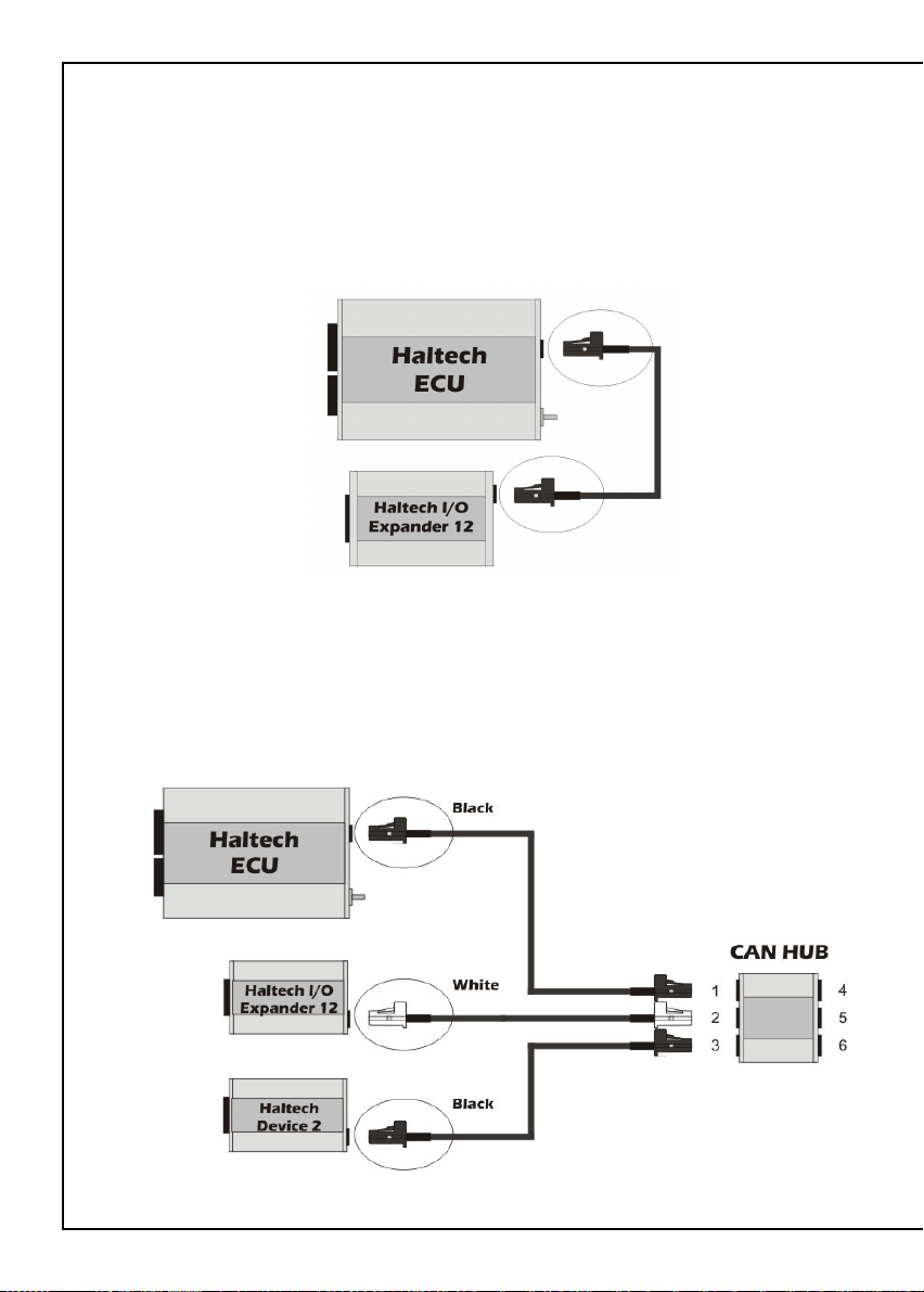
Method 1: Direct Connection to Haltech Platinum Series ECU
• Connect the Haltech I/O Expander 12 directly to a Haltech Platinum series ECU via
the CAN direct connection cable included with the kit
Figure 1 – Direct connection to Haltech ECU
Method 2 : Connection Via Haltech CAN Hub ( HT059990)
• Connect the Haltech I/O Expander 12 directly to the CAN Hub attached to a Haltech
Platinum Series ECU ( a Haltech CAN Hub Connection Cable may need to be
purchased depending on your setup. Please refer to the Haltech CAN Hub quick start
guide for details on connecting multiple devices to your Platinum Series ECU.)
Figure 2 – CAN Hub connection to Haltech ECU with 2 Devices
Page 5

Wiring Harness (optional)
The Haltech I/O Expander 12 can be supplied with a 24 pin wiring harness,
Connections are outlined in detail below:
WARNING!
Please make sure you configure your I/O Expander 12 with your ECU using
ECU Manager Software before you plug in the wiring harness, as outputs may
turn on undesirably when power is applied if not configured.
Main Inputs
There are four main inputs to the Haltech I/O Expander 12
+12V DC Switched (Pink)
Connect this wire to a +12V DC Switched ignition source
+12V DC Battery (Red)
Connect this wire to a constant +12V DC battery supply
Signal Ground (Black / White)
Connect this wire to the signal ground on the ECU
Ground (Black)
Connect this wire to a chassis ground point on the vehicle
Figure 1- Main inputs
Page 6
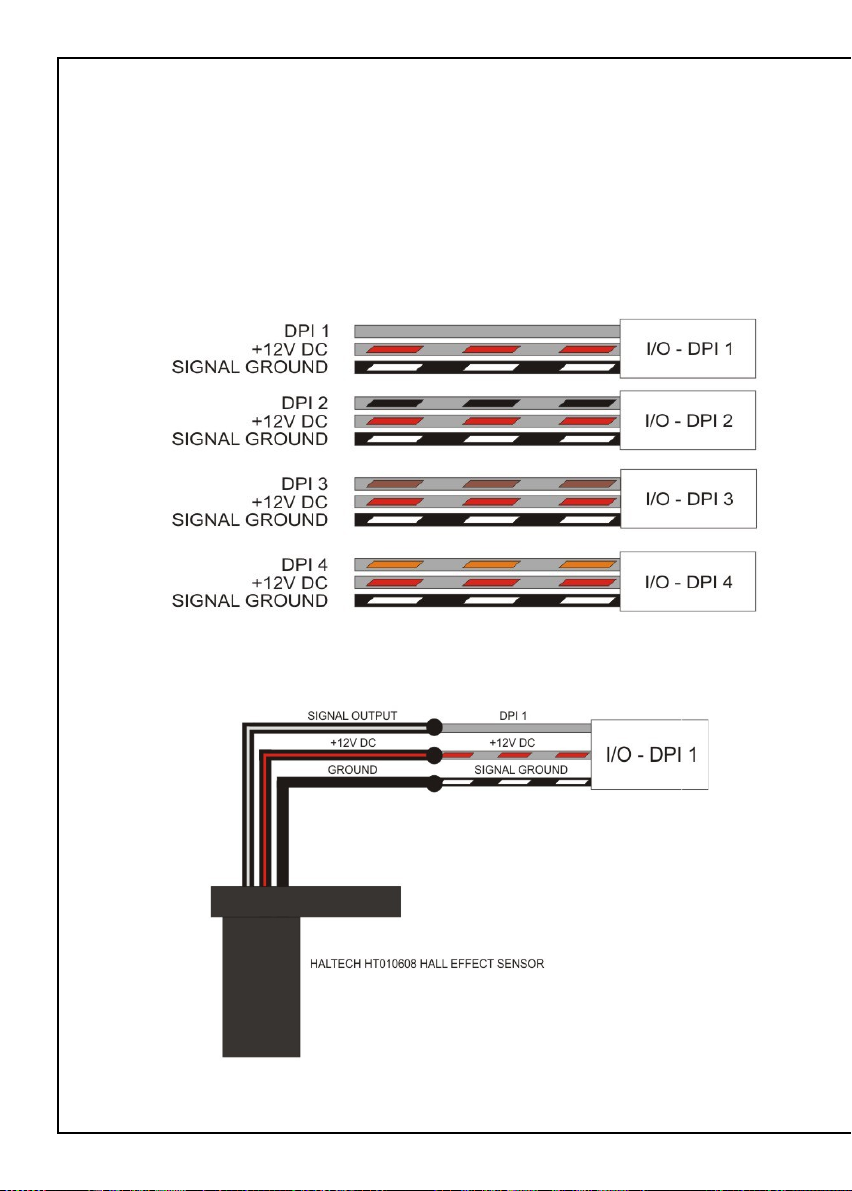
Digital Pulsed Inputs ( DPI )
The Haltech I/O Expander 12 features 4 Digital Pulsed Inputs. Each input has been
grouped with a +12V DC Source and a signal ground within the harness, this allows
the user to fit an external pull-up to 12V or pull- down to ground resistor if required
and or to supply power to a 12V rated sensor.
Digital Pulsed Inputs are capable of accepting pulsed input information such as
for a road speed sensor. These inputs measure the time periods between the pulses
and can process this information to provide quantities such as road speed.
Figure 2 - Digital Pulsed Inputs
Figure 3 - Haltech HT1010608 wiring to DPI 1
Page 7

Analogue Voltage Inputs ( AVI )
The Haltech I/O Expander 12 features 4 Analogue Voltage Inputs. Each input has
been grouped with a +5V DC Source and a signal ground within the harness, this
allows the user to fit an external pull-up to 5V or pull-down to ground resistor
if required and or to supply power to a 5V rated sensor.
Analog Voltage Inputs accept variable voltage inputs from 0V to 5V.
AVI inputs can also accept switch inputs that change between two different voltage
levels. The On Voltage and Off Voltage define the thresholds between the On and Off
states. The input voltage can be viewed as a channel in the software to determine the
thresholds for a switched input.
Figure 4 - Analogue Voltage Inputs
Figure 5 - Haltech HT010302 Coolant Temperature Sensor wiring to AVI 1
Page 8

Digital Pulsed Outputs ( DPO )
The Haltech I/O Expander 12 features 4 Digital Pulsed Outputs. Each output has
been grouped with a +12V DC Source within the harness, this allows the user to fit
an external relay to control high current devices.
Digital Pulsed outputs are capable of outputting pulsed waveforms with varying duty
and frequency. DPO's can be used to control various devices such as thermo fans,
shift lights, bypass air control valves, boost control solenoids etc.
When a Digital Pulsed output is activated by the ECU the output will switch to ground.
Solenoid valves and shift lights etc can be run directly from the output. However
high current devices such as thermo fans and additional fuel pumps must be
activated through a relay. This way the DPO is only switching a relay and not a high
current draw device.
Digital Pulsed Outputs are limited to 1A Max current draw.
Figure 6 - Digital Pulsed Outputs
Figure 7 - Digital Pulsed Output Relay Wiring
Page 9
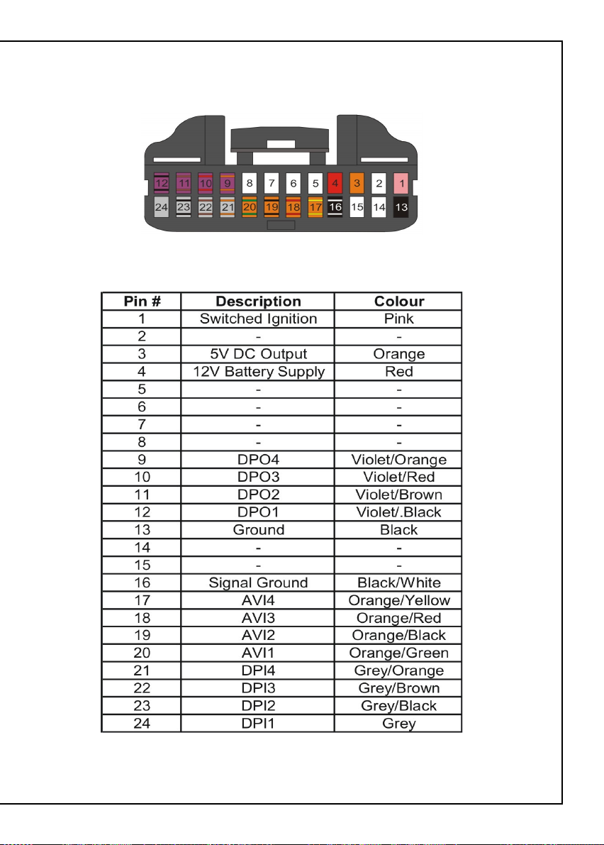
Appendix
Looking into the wire side of the connector
Figure 8 - Wiring Harness pinout information
Page 10

Notes
Page 11

Page 12

HALTECH HEAD OFFICE: PH: +612 9729 0999
FAX: +612 9729 0900
EMAIL: sales@haltech.com
HALTECH US OFFICE: EMAIL: usa@haltech.com
See the Haltech Website for your local authorized dealer.
www.haltech.com
Version 1
 Loading...