

Page 1

Introduction.........................................................................................1
Installation Overview ........................................................................................................1
Before You Begin..............................................................................................................2
Tool/Supply Requirements................................................................................................3
How It Works ....................................................................................................................4
The Features of the IG5.....................................................................................................4
Haltech IG5 Specifications....................................................................................................5
SECTION 1 Getting Started............................................................8
CHAPTER 1 Haltech IG5 Installation ............................................................................8
1.1 Overview .....................................................................................................................8
1.2 Installation Summary...................................................................................................8
1.3 Expanded Installation Guide ......................................................................................9
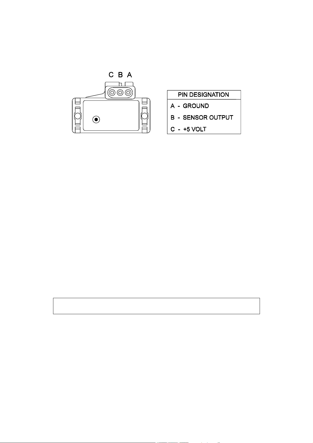
1.3.1. Manifold Absolute Pressure (MAP) Sensor.......................................................9
1.3.2. Coolant Temperature Sensor............................................................................10
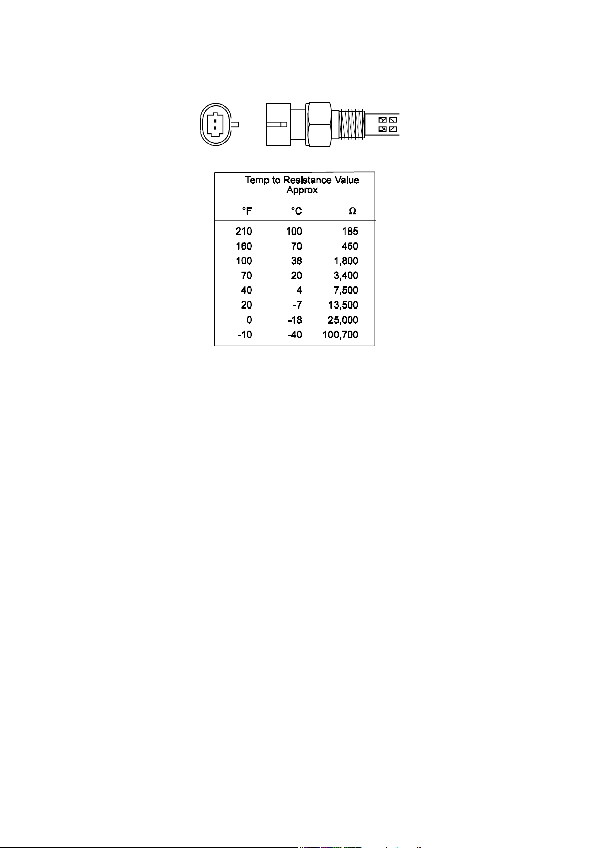
1.3.3. Inlet Air Temperature Sensor ...........................................................................10
1.3.4. The Throttle Position Sensor (TPS) .................................................................12
1.3.5. Mounting the Igniter.........................................................................................12
1.3.6. Route Wiring Harness and Connect Sensors....................................................14
1.3.7. Power Relays....................................................................................................14
1.3.8. Electronic Control Unit (ECU) .......................................................................15
1.3.9. Flying Leads .....................................................................................................15
1.3.10. Install and connect any Optional Outputs ......................................................15
1.3.11 Connect the Trigger Sensor..............................................................................15
1.3.12 Connect the ECU..............................................................................................16
CHAPTER 2 Getting Online .........................................................................................17
2.1 Connecting the Haltech IG5 to a Computer ..............................................................17
2.2 Operating the Software.............................................................................................17
2.2.1 Computer Requirements.....................................................................................17
2.2.2 Installing the Software........................................................................................18
2.2.4 Running the Software from the Floppy Disk. ....................................................19
2.2.5 Azerty Keyboards...............................................................................................20
2.3 The Online and Offline Modes..................................................................................20
2.4 Using the System Online...........................................................................................20
2.5 The Main Menu.........................................................................................................21
2.6 How to Quit...............................................................................................................21
2.7 Checking the Engine Data.........................................................................................21
CHAPTER 3 Engine Identification ...............................................................................22
3.1 Setting Engine Identification.....................................................................................22
3.2 Ignition Set-up...........................................................................................................23
Chapter 4 Using Haltech Software...................................................................................26
4.1 Using the Software ....................................................................................................26
4.2 What is mapping the Engine?....................................................................................26
4.3 What are maps? .........................................................................................................26
4.4 Accessing the Ignition Maps .....................................................................................27
4.5 The Ignition Maps .....................................................................................................27
4.6 Altering a Map...........................................................................................................28
4.7 How To Quit..............................................................................................................29
4.8 Time Saving Functions..............................................................................................29
ii
Page 2

4.8.1 Current Location.................................................................................................29
4.8.2 All Ranges ..........................................................................................................29
4.8.3 Selecting Groups of Bars....................................................................................30
4.8.4 Percentage Changes............................................................................................30
4.8.5 Linearise .............................................................................................................30
4.8.6 Numeric Mode....................................................................................................30
4.8.7 Bar Increments....................................................................................................30
4.8.8 Online Help ........................................................................................................31
4.9 Command Summary for Maps .................................................................................32
Chapter 5 Starting the Engine ..........................................................................................33
5.1 Calibrate the Throttle Position Sensor .....................................................................33
5.2 Check the trigger signal............................................................................................33
5.3 Check the Base Timing ............................................................................................33
5.4 Loading an Ignition Library Map .............................................................................34
5.4.1 On the Dyno .......................................................................................................35
5.4.2 On the Road........................................................................................................36
SECTION 2 Other Adjustable Features......................................37
Chapter 6 Cold Starting and Running..............................................................................37
6.1 Cold Cranking ..........................................................................................................37
Chapter 7 Correction Factors ...........................................................................................38
7.1 The Ignition Coolant Map .........................................................................................38
7.2 The Ignition Inlet Air Temperature Map..................................................................38
SECTION 3 Software Features.....................................................39
Chapter 8 File Storage and Retrieval ...............................................................................39
8.1 Saving Maps and Identification................................................................................39
8.1.1 The Save Command ...........................................................................................39
8.1.2 Giving Your Map A Filename............................................................................39
8.2 Loading Maps and Identification..............................................................................40
8.3 File Management......................................................................................................40
8.3.1 Erasing Unwanted Maps ....................................................................................40
8.3.2 Changing Directories..........................................................................................41
Chapter 9 Printing Maps ..................................................................................................42
9.1 The Print Function....................................................................................................42
Chapter 10 DataLog.......................................................................................................43
10.1 The Data-log Option...............................................................................................43
10.1.1 Setting Up the Data-log Page ...........................................................................43
10.1.2 Creating a Data-log ..........................................................................................43
10.1.3 Viewing the Datalog.........................................................................................44
10.1.4 Data-Log File Management..............................................................................44
10.1.5 Printing Datalogs..............................................................................................45
Chapter 11 Customising the Software ...........................................................................46
11.1 The Set-up Page......................................................................................................46
11.1.1 The Display ......................................................................................................46
11.1.2 Com Port ..........................................................................................................46
SECTION 4 IG5 Optional Outputs..............................................47
Chapter 12 Software Access ..........................................................................................47
iii
Page 3

12.1 The Output Options Page .......................................................................................47
12.2 Enabling Options....................................................................................................47
Chapter 13 Auxiliary Outputs........................................................................................48
13.1 Description ..............................................................................................................48
13.2 Turbo Waste Gate Control (TWG).........................................................................48
13.2.1 Description .......................................................................................................48
13.2.2 Using the Turbo Waste Gate Control...............................................................49
13.2.3 Using the Boost Controller...............................................................................50
13.3 Dual Intake Valve Control (DIV)...........................................................................51
13.4 Torque Converter Lockup (TCC)..........................................................................52
13.5 Electric Thermatic Fan Control (TF)......................................................................53
13.6 Electric Intercooler Fan Control (IF).....................................................................54
13.7 Shift Light Illumination (SL)..................................................................................54
13.8 Anti-Stall Solenoid Control (AS)...........................................................................55
13.9 Turbo Timer (TT)....................................................................................................55
13.10 NOS Switch...........................................................................................................56
SECTION 5 Appendices ................................................................58
Appendix A Troubleshooting ..........................................................................................58
A.1 Overview .................................................................................................................58
A.2 Control Program Problems......................................................................................59
A.3 Starting problems .....................................................................................................60
A.4 Idling Problems ........................................................................................................60
Appendix B ..................................................................................................................61
B.1 The IG5 Outputs ......................................................................................................61
B.2 Direct Fire Ignition ..................................................................................................62
B.2.1 Ignition Outputs.................................................................................................62
B.2.2 Coil Setup ..........................................................................................................62
B.2.3 Converting Individual Coils to Waste Spark.....................................................63
B.3 Rotary Engines..........................................................................................................63
B.4 Igniters ......................................................................................................................64
B 4.1 Constant Charge or “Dumb Igniters”.................................................................65
B.5 Alternative Ignition Systems ....................................................................................66
B.6 Pull-up Resistor Dip Switch Settings .......................................................................68
Appendix C Trigger Inputs ..............................................................................................69
C.1 The Input Trigger.....................................................................................................69
C.2 Trigger Devices ........................................................................................................70
C.2.1 Hall Effect Sensors ............................................................................................70
C.2.2 Optical Sensors ................................................................................................76
C.2.3 Magnetic Reluctor Sensors................................................................................76
C.3 Home Signal (synchronising) ..................................................................................78
C.3.1 Multitooth Triggers............................................................................................79
C.3.2 Motronic Triggers..............................................................................................79
C.3.3 Twin Triggers and Twin Distributors................................................................80
Appendix D Rotor Phasing ..............................................................................................81
iv
Page 4

Under copyright law, neither this manual nor its
accompanying software may be copied, translated or
reduced to electronic form, except as specified
herein, without prior written consent of Invent
Engineering Pty Ltd trading as Haltech.
Copyright 1999 Invent Engineering Pty Ltd
A.C.N. 000 613 832
Also trading as HALTECH
10 Bay Road
Taren Point, NSW 2229
Australia
Ph: (+61) (02) 9525 2400
Fax: (+61) (02) 9525 2991
Sales-au@haltech.com
Haltech USA
Suite 309, 2156W
Northwest Highway
Dallas Texas
USA
Ph: (+1) (972) 831 9800
Fax: (+1) (972) 831 9802
Sales-us@haltech.com
www.haltech.com
MS_DOS is a registered trademark of Microsoft
Corporation. IBM is a registered trademark of
International Business Machines Corporation
Print Version: 3.0 ...................................................................................... Date: 3 August 2000
This manual should accompany:
IBM compatible PC software .....................................................................................v1.4
Firmware Series ...............................................................................................................4
Firmware..................................................................................................................... v1.4
v
Page 5

Introduction
Congratulations on your decision to install a Haltech Ignition System to your vehicle. Haltech
systems have been successfully installed on thousands of vehicles, from power off-shore boats
to twin-turbo Ferraris, from pylon racing aircraft to jet skis and snowmobiles. Over the past
several years, many motor sport enthusiasts have discovered that the Haltech computer is easy
to use and gets the job done correctly - that job being to reliably make a lot of horsepower and
torque in an engine by enabling users to precisely control ignition timing. Precise ignition
control also leads to excellent drivability and fuel economy - something that is often lacking
in high-performance engines.
Haltech users have discovered that the flexibility of the Haltech Electronic Control Unit
(ECU) and PC based programming software leads to the easiest possible installation on
everything from traditional pushrod V8s to high performance turbocharged racing
motorcycles. We are proud of the fact that some of the most respected professional racers and
supercar builders in the world use Haltech equipment for the same reasons that Haltech is
popular with motor sports enthusiasts: it is flexible and friendly, is installed easily and you can
tune your Haltech simply, without having to make the project a major research effort.
Installation Overview
The Haltech IG5 system utilises a special-purpose programmable microcomputer designed for
engine management. The IG5 system includes the ECU, engine sensors, and a special wiring
harness to connect them, plus programming software and cable for tuning the system.
Installation requires the mounting of four electronic engine sensors; two for temperature, one
for throttle position and one to sense intake manifold pressure. A harness is supplied for
connecting the 12V, ground and signal wires, and plugs to the engine sensors. An igniter will
be mounted in the engine bay and connected to the harness or the original igniter may be used.
Finally the ECU is mounted. The ECU requires a trigger with a fixed timing relationship to
the engine crankshaft from a distributor, crank angle sensor, or cam angle sensor. If you
vehicle lacks one or more of these components, your Haltech dealer can help you obtain them.
When component installation is completed an IBM compatible PC is connected to the ECU
via the supplied communications cable. The Haltech Programming software then allows you
to configure the IG5 to your engine requirements. The programming software has been
designed to be functional, "friendly" and intuitively easy to use.
For initial engine start up the ECU has a quick map feature This feature which is discussed in
more detail later in the manual offers you a simple and effective way of forming an ignition
curve as a starting point. Once the motor is running, fine-tuning to develop maximum
performance can be easily accomplished through the Haltech software.
1
Page 6

Before You Begin...
1) IT IS BEST TO READ THIS ENTIRE MANUAL BEFORE STARTING.
At the very least you should read Section One of the manual and the Appendices relevant to
your installation. The greater your knowledge of the operation of the Haltech system, the
easier you will find it to understand what you are doing, and why. Throughout the manual are
Warnings and Notes that will help your installation run smoothly and indicate the dangers that
can exist for you the installer and the Haltech ECU.
2) Read any additional material accompanying this manual that updates the document since it
was written.
3) You may need special parts or additional tools or test equipment in order to complete
installation. Make sure you have these items on hand before you begin to avoid frustration.
Contact your Haltech dealer if you have difficulty.
4) Don't do the minimum work possible. Carelessness in the early stages of installation can
cause you major headaches later on, be it in a few days or a few months time. Carelessness
will cost you money and frustration in finding and fixing unnecessary problems. You have
the opportunity to make sure your Haltech system's operation is extremely dependable and
easy to use by doing it right the first time.
WARNING:
AVOID OPEN SPARKS, FLAMES, OR OPERATION OF
ELECTRICAL DEVICES NEAR FLAMMABLE SUBSTANCES.
ALWAYS DISCONNECT THE BATTERY CABLES WHEN DOING
ELECTRICAL WORK ON YOUR VEHICLE.
DO NOT CHARGE THE BATTERY WITH A 24VOLT TRUCK
CHARGER OR REVERSE THE POLARITY OF THE BATTERY OR
ANY CHARGING UNIT
DO NOT CHANGE THE BATTERY WITH THE ENGINE RUNNING
AS THIS COULD EXPOSE THE ECU TO AN UNREGULATED
POWER SUPPLY THAT COULD DESTROY THE ECU AND OTHER
ELECTRICAL EQUIPMENT.
ALL FUEL SYSTEM COMPONENTS AND WIRING SHOULD BE
MOUNTED AWAY FROM HEAT SOURCES, SHIELDED IF
NECESSARY, AND WELL VENTED.
MAKE SURE THERE ARE NO LEAKS IN THE FUEL SYSTEM AND
THAT ALL CONNECTIONS ARE SECURE.
2
Page 7

DISCONNECT THE HALTECH ECU FROM THE ELECTRICAL
SYSTEM WHENEVER DOING ANY ARC WELDING ON THE
VEHICLE BY UNPLUGGING THE WIRING HARNESS CONNECTOR
FROM THE ECU.
5) Electromagnetic interference (EMI) from unsuppressed spark plugs and leads can cause the
ECU to fail. Please do not use them.
6) In hot climates, or with turbocharged engines, you may need to employ heat shielding to
prevent heat soak and damage to electrical and fuel parts. Use the coolest surfaces of the
chassis as a heat sink for components and use thermally conductive brackets where
appropriate.
7) IGNITION MODULES It is essential that the user fully understands what type of ignition
module (igniter) is to be used with the Haltech ECU. Constant charge and constant duty igniters
are available and the ignition set-up page must be set accordingly before power is applied and the
ignition modules are connected to the main loom. Failure to do so may damage the igniters and
coils.
Constant Duty is used with “Intelligent” igniters such as the Haltech supplied EB023. Constant
Charge is used with “Dumb” igniters that can also be obtained from Haltech as single, double or
triple igniters.
Most standard OEM supplied igniters are of the “dumb” type but if in any doubt it is necessary to
check or purchase suitable igniters through your Haltech supplier.
WARNING:
HALTECH WILL NOT REPLACE ANY IGNITION COMPONENTS
DAMAGED BY FAILURE TO COMPLY WITH THE ABOVE
PROCEDURES.
Previously Haltech ECU’s were only compatible with constant duty type igniters; therefore
numerous references are made to the EB023 BOSCH module which is supplied by Haltech.
Haltech can supply both constant duty and constant charge modules to suit the IG5. Many of the
modules have a similar external appearance and it is essential that the installer be able to identify
the unit as constant charge or constant duty.
Note: In this manual, reference will be made to a MAP sensor (Manifold
Absolute Pressure sensor) and the ignition maps that are tables stored in the
ECU. Both are common industry terms but with entirely different meanings.
Tool/Supply Requirements
Installation of this system can be easily carried out by professional mechanics and most
experienced home mechanics if the following tools and components are available:
Voltmeter or Test Light
A selection of screwdrivers and spanners
Soldering Iron and solder (we recommend soldering all connections)
3
Page 8

Wire Cutters and Pliers
Crimping Tool and assorted terminals
Drill with assorted drill bits
3/8" NPT Tap
1/4" GAS Tap
Electrical Tape or Heat Shrink tubing
Teflon pipe sealing tape
Nylon cable ties
Jeweler’s file (may be needed for mounting Throttle Position Sensor)
Mounting hardware for ECU and relays (mounts/bolts/screws)
IBM-PC compatible computer (preferably laptop) with at least 640kb, one disk drive and an
RS232 serial port.
A good quality Timing Light
How It Works
The Haltech IG5 uses a digital microcomputer to measure engine speed and load and uses these
values to access a look-up table of ignition advance (°BTDC). This look-up table is called a base
ignition map and is stored in non-volatile memory (i.e. memory which is retained when power is
switched off). Programming software allows the contents of this memory to be changed to match
the requirements of the engine.
The Features of the IG5
The IG5 is designed to be easily programmed and is capable of being used on a wide variety of
applications. A typical IG5 installation could be 4, 6 or 8 cylinders, turbo/supercharged or
normally aspirated, distributed ignition (only one ignition output) or Direct Fire ignition (multiple
ignition coils). It will also provide the ability to control some other features, such as Turbo
Wastegate Control, Thermofans, Torque Converter Clutch Lockup, etc.
Note: You should read Appendix B & C before you install the system to be
fully aware of your hardware and installation requirements.
The following variants are catered for by the Haltech IG5 system
Direct Fire Ignition
Rotary Engines
Twin Triggers
Twin Distributors
Multitooth Trigger Systems
The above will be determined by your engine configuration. If your engine has no distributor, for
example, you will need to use Direct Fire. All the features will be determined by your engine setup.
4
Page 9

HALTECH IG5 SPECIFICATIONS
Engine Suitability
• Up to 16,000 rpm
• 1, 2, 3, 4, 5, 6, 8, 10, 12 or 16 cylinders (1-2 rotors)*
• 2 or 4 stroke
• Normally aspirated or supercharged up to 200 kPa (30 psi) – Higher boost pressure MAP sensors
available by special arrangement
• Load sensing by throttle position or manifold pressure
• Distributed ignition systems, or direct fire systems with 1 to 4 coils
Power Requirements
•••• Power Source
8.6 to 16 Volts DC
•••• Consumption
Haltech ECU: 270 mA at 12 Volts
Physical Specifications
• ECU Dimensions
Length: 153 mm (6 1/16")
Width: 105 mm (4 1/8")
Depth: 32 mm (1 1/4")
• Weight
ECU: 760g (1.68 lb)
Loom: 1.92kg (4.2 lb)
Sensors: 500g(1.1 lb)
Shipping Weight: 4.5kg (9.9 lb)
(Including manual/packaging)
Input Sensors
• Manifold Absolute Pressure (MAP) Sensor, (optional at extra cost)
1 Bar -100kPa to 0kPa (Naturally Aspirated)
2 Bar -100kPa to 100kPa (up to 1 Bar or 15 psi boost)
3 Bar -100kPa to 200kPa (up to 2 Bar or 30 psi boost)
Higher boost pressure MAP sensors available by special arrangement
• Temperature Sensors (Air and Coolant), (optional at extra cost)
NTC temperature dependent resistor type.
Operating Range
Continuous -40°C to 100°C (-40°F to 212°F)
Intermittent up to 125°C (257°F)
• Throttle Position Sensor, (optional at extra cost)
10 kΩ rotary potentiometer driven from throttle shaft
5
Page 10

• Engine Speed Pickup
Compatible with most trigger systems:
- 5 or 12-volt square wave;
- Pull-to-ground (open collector)
A Reluctor adaptor is available for magnetic (or ‘reluctor’) triggers supporting most standard tooth
patterns. Applications requiring a motronic trigger input need to be specified at the time of order.
Only a 60-tooth wheel with 2 teeth missing is supported.
ECU Outputs
• Ignition Output
(May also be compatible with other igniters. Ask your Haltech dealer.)
Optional ECU triggered Haltech Ignition Module for firing the coil.
System Programming Requirements
• Computer
IBM-PC or compatible, preferably laptop or notebooks
CGA, EGA or VGA, colour or monochrome display
640+ kb RAM
• Disk Drive
3.5" Floppy Disk Drive
(5.25" disk available on request)
• Serial Port
Standard RS232C port - 9 pin D connector
(25 pin cable available on request)
COM1 or COM2 (selectable)
Adjustable Features
• Ignition Map
22 Ignition ranges, every 500 RPM to 10,500, or
17 Ignition ranges, every 1000 rpm to 16,000
32 Load points per range, up to 50° advance, with 1° resolution
6
Page 11

• Correction Maps
• Ignition
Crank Advance - 32 points
Coolant Temperature Advance/Retard - 32 points
Air Temperature Advance/Retard - 32 points
• Programmable Rev-Limit
• Programmable Output Options
• Turbo Wastegate Control
• Dual Intake Valve Control
• Torque Converter Lock-Up
• Electric Thermatic Fan Control
• Intercooler Fan Control
• Shift Light
• Anti-Stall Solenoid Control
• Turbo Timer
• NOS Switch
Miscellaneous
• Map Storage and Retrieval
Maps may be stored to disk and re-used
• Datalogging
Engine data information saved at a nominal rate of 10 samples per second.
Data storage to memory or disk.
Limited only by available memory (approx. 11k/minute).
• US or Metric Units
• Real Time Programming
Instant, hesitation free adjustment while engine is running
•••• Optional Ignition Trim Module
Provides -8° to +7° adjustment for fast tuning
• Rugged Aluminium Casing
Black anodised with integral cooling fins and mounting brackets.
– cuts ignition preventing over revving of the engine
7
Page 12

SECTION 1 Getting Started
CHAPTER 1 HALTECH IG5 INSTALLATION
1.1 Overview
The Haltech IG5 system comprises the following components
Haltech Electronic Control Unit (ECU)
Main Wiring Harness
Haltech IG5 system Instruction Manual
Programming Cable
Programming Disk
Relay
Optional Items (at extra cost)
Coolant Temperature Sensor
Inlet Air Temperature Sensor
Throttle Position Sensor (TPS)
Manifold Absolute Pressure (MAP) Sensor, (1,2 or 3 Bar)
Ignition Module
Ignition Timing Trim Control
Reluctor Adaptor - for magnetic triggers
Ignition Coils
Haltech Dual Hall-Effect sensor
1.2 Installation Summary
1. Mount Manifold Absolute Pressure Sensor. (If applicable)
2. Mount Coolant Temperature Sensor. (If applicable)
3. Mount Inlet Air Temperature Sensor. (If applicable)
4. Mount Throttle Position Sensor. (If applicable)
5. Mount Ignition Module
7. Route Main Wiring Harness and connect sensors and ignition module.
8. Mount and connect Power Relay.
9. Mount ECU inside passenger compartment.
10. Locate and connect flying wires:-
RED + 12 volts battery
GREY Ignition on 12 volts
BLACK Chassis ground
11. Install and connect any Optional Outputs
12. Connect Trigger signal
13. Connect ECU and test.
8
Page 13
1.3 Expanded Installation Guide
1.3.1. Manifold Absolute Pressure (MAP) Sensor
The MAP sensor is used to convert the manifold pressure into an electrical signal for the IG5
ECU to use. The sensor works in absolute pressures, thus its calibration is not affected by
changes in barometric pressure.
There are three types of MAP sensors that can be used with the IG5 system. The sensor
required depends on the specific engine configuration.
1 Bar Sensor (Part No. 039 4070)
( -100kPa to 0 kPa) Normally Aspirated Engines
2 Bar Sensor (Part No. 886 3189)
(-100kPa to 100kPa) Turbo or Supercharged
Engines up to 100kPa boost
(15 psi , 1 atmosphere)
3 Bar Sensor (Part No. 749 3169)
(-100kPa to 200kPa) Turbo or Supercharged
Engines up to 200kPa boost
(30 Psi, 2 atmospheres)
Note: Make sure you have the correct MAP sensor for your engine. The first
three digits of the part number is stamped on the sensor housing.
Mounting
The MAP sensor is usually mounted high on the engine bay firewall or inner guard using two
screws with the hose nipple facing outwards. Connect the sensor to the inlet manifold via a
short length of vacuum hose and fasten with either hose clamps or nylon cable ties. Connect
the sensor to the main wiring harness using the appropriate plug. (For 1 Bar sensors the plug
is green, for 2 and 3 Bar sensors the plug is orange). Avoid mounting the sensor below the
level of the fuel system, because fuel may collect in the vacuum hose and run down into the
sensor. The sensor assembly is weather-proof but it is good practice to mount the sensor in a
protected position away from moisture and heat.
9
Page 14
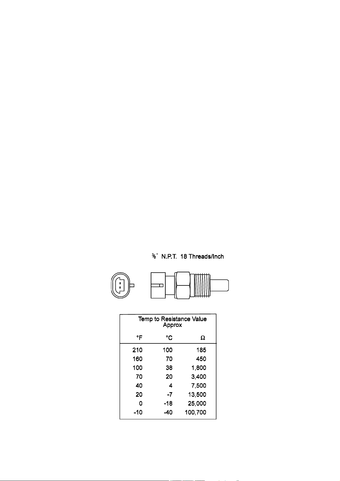
1.3.2. Coolant Temperature Sensor
The coolant temperature is used by the computer to determine the required corrections to
ignition timing.
The coolant temperature sensor has a solid brass temperature sensing tip. Refer to the
diagram for technical details of the sensor. The coolant sensor supplied is an industry
standard component and some engines may already have provision for this type of sensor.
The coolant temperature sensor is designed to screw into a threaded hole and protrude into the
engine coolant stream. For air-cooled engines, the sensor can be embedded directly into the
engine block or used to sense oil temperature.
Locate a suitable position on the engine which will allow the hole and thread to be machined,
and which gives access to the coolant stream. The sensor should be mounted before the
thermostat in the coolant circuit. Since most engines have existing temperature sensor holes,
it is often possible to mount the Haltech sensor in one of these holes. A thread adaptor is
sometimes necessary. In some engines only one temperature sensor hole exists and is used for
the dashboard gauge sender.
If it is necessary to drain the coolant from the vehicle to fit the temperature sensor then the
factory manual for the engine should be consulted for the correct procedure to restore the
coolant and purge the cooling system of air.
1.3.3. Inlet Air Temperature Sensor
10
Page 15
14mm x 1.5
The air temperature sensor is used to compensate for changes in air density due to air
temperature. This effect is most noticeable in forced induction engines. The Haltech IG5 will
allow compensation for ignition timing using the signal received from the air temperature
sensor.
The sensor should be mounted to provide the best representation of the actual temperature of
the air entering the combustion chamber, ie. after any turbo or supercharger, and intercooler,
and as close to the head as possible. The sensor needs to be in the moving air stream to give
fast response times and reduce heat-soak effects.
Note: The Haltech air temperature sensor will read temperatures up to 120° C
and temperatures above this will be interpreted as a fault condition. The air
temperature after some turbocharger's and superchargers can exceed this. If
this occurs with your engine you should consider fitting an intercooler to
reduce air temperature and increase charge density. If this is not possible then
the air temperature sensor should be placed upstream of the turbo or
supercharger to monitor ambient air temperature.
Once a suitable position has been located for the air temperature sensor a hole should be
drilled and tapped to accept the sensor. Remove the manifold or inlet tract from the engine
before machining the sensor mount. Do not allow any metal particles to enter the inlet
manifold of the engine as these will be drawn into the engine and damage it. Wash all
components thoroughly before reassembly.
11
Page 16
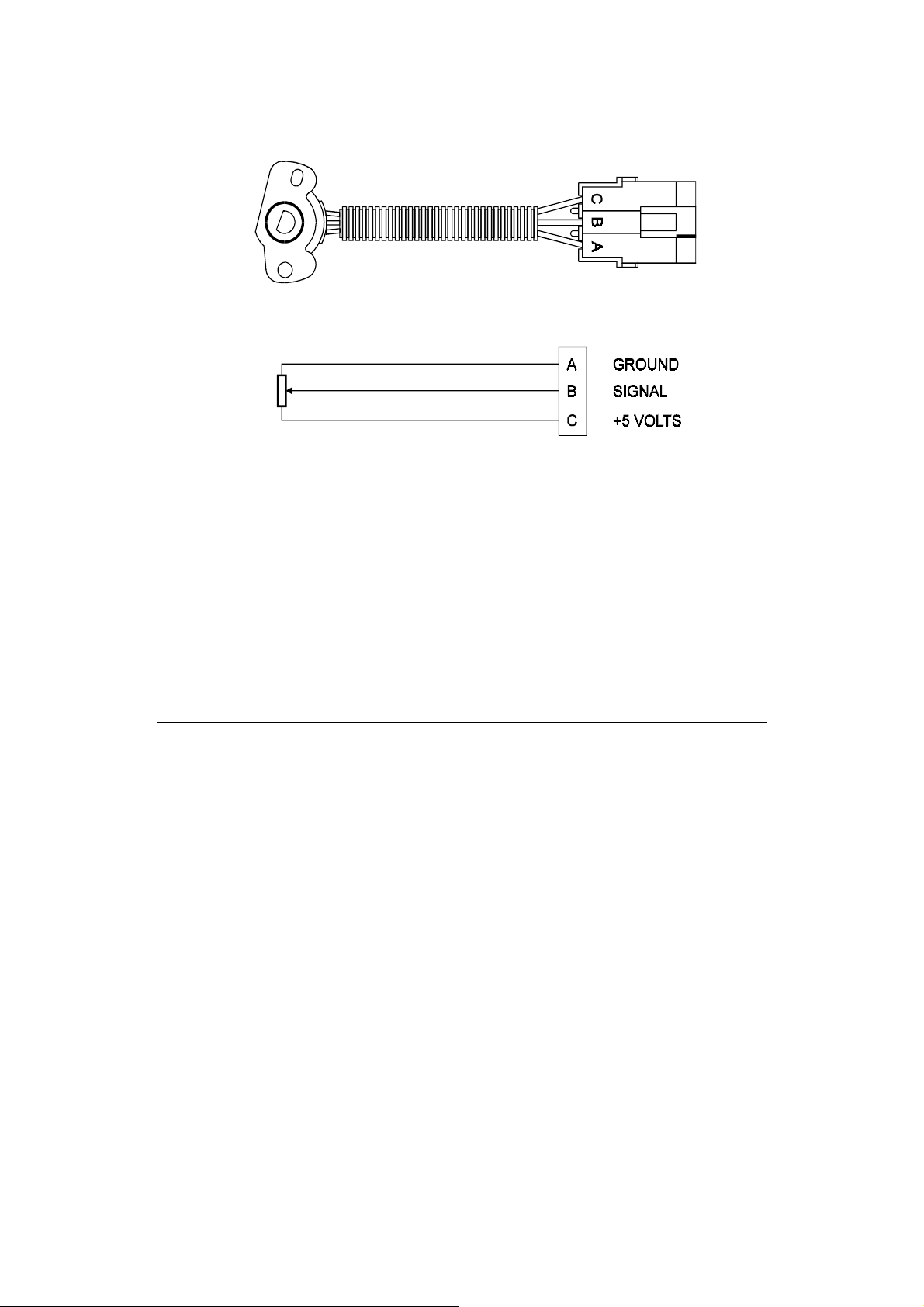
1.3.4. The Throttle Position Sensor (TPS)
The throttle position sensor is mounted to the throttle butterfly shaft to sense its rotation. A TPS is
common on many late model engines and the Haltech sensor should attach with little or no
modification. The throttle shaft must protrude from the side of the throttle body. This may require
the machining of the throttle body or the manufacture of a new throttle shaft. The inner mechanism of
the sensor rotates with the shaft. If the shaft is round then file a flat surface on the shaft so that it will
pass through the sensor assembly. The TPS should be mounted against the side of the throttle body,
using two screws, such that the throttle shaft and the sensor mechanism can rotate freely. Make sure
that the axis of rotation of the shaft is exactly aligned with the axis of rotation of the sensor.
Also, do not use the TPS as a throttle stop. In either case, the TPS will be damaged. The
absolute range of sensor movement is not important as the sensor can be calibrated using the
programming software.
Note: If a Throttle Position Sensor is already fitted this sensor can often be
used instead of a Haltech supplied TPS. The rotary potentiometer in the
Haltech TPS has 10k Ω resistance value but the alternate TPS can have a
different value as the software allows calibration of the throttle input.
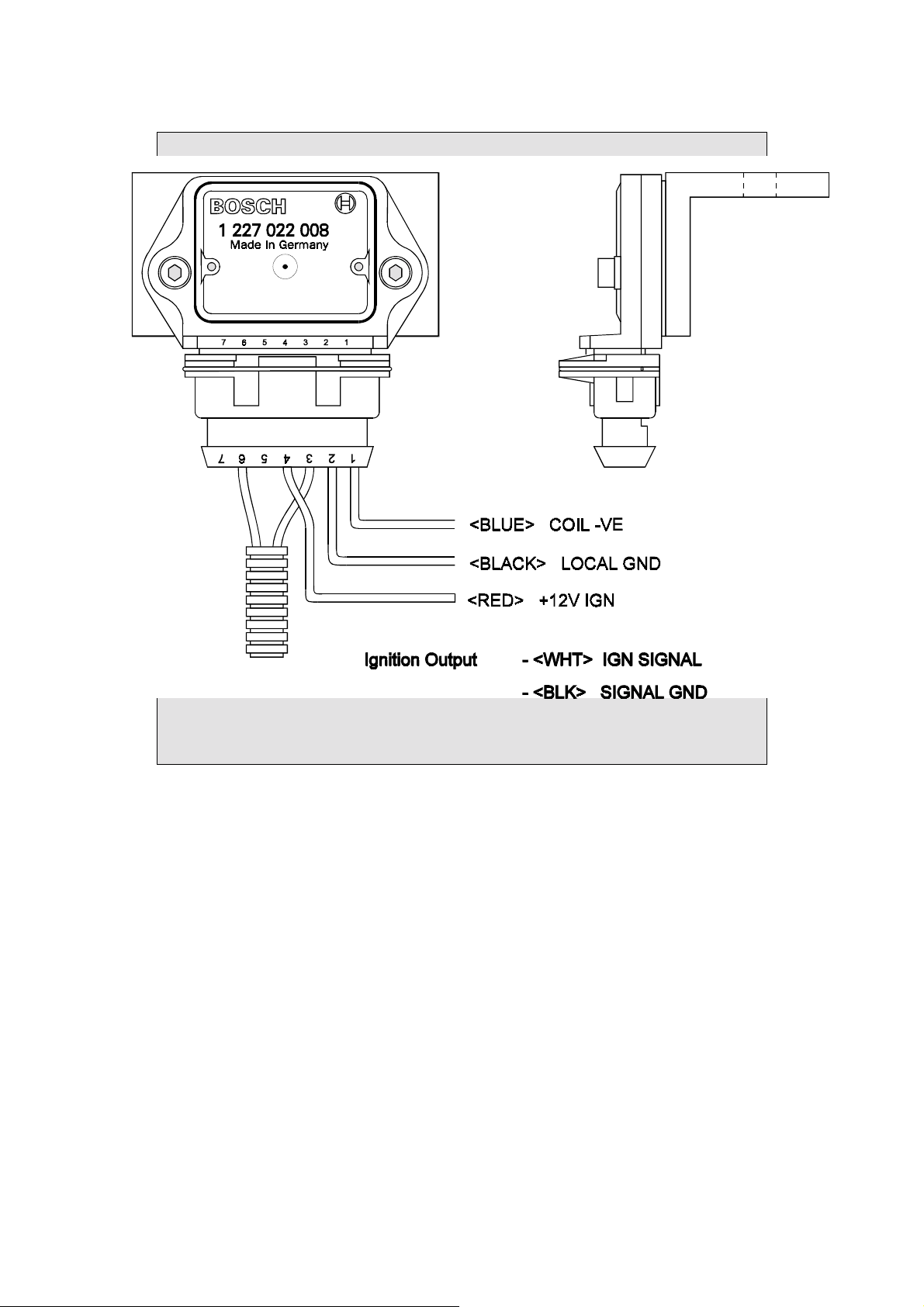
1.3.5. Mounting the Igniter
The igniter must be mounted on a flat surface (eg. the firewall) to ensure proper heat dissipation and
to avoid stress on the wiring connections. It is important to protect the module from overheating by
mounting it away from hot components such as exhaust manifolds and turbocharger's.
Included with the Bosch Ignition Module (the EB023 supplied by Haltech) is the ignition subloom. This connects the Ignition module to the Main Harness. Locate this loom and connect
it to the ignition module but do not connect the ignition sub-loom to the main loom until
the ignition settings in the ECU are verified by connecting the ECU to a computer.
Connect the 3 flying leads of the ignition sub-loom. The black wire with the eye terminal is a ground
connection. This should NOT be grounded to the same point as the ECU to prevent ignition noise
getting into the power supply circuit of the ECU. The blue wire goes to the negative side of the coil.
The red wire should be supplied with 12 volts when the ignition is on. This can often be obtained
from the positive side of the coil.
12
Page 17
WARNING:
NOTE: IF USING THE BOSCH IGNITION MODULE (THE EB023
SUPPLIED BY HALTECH ON AN ANGLE BRACKET) CONSTANT
DUTY SHOULD BE SELECTED IN THE IGNITION SETUP PAGE.
Bosch Ignition Module. The module must be mounted on the bracket, and the bracket must be
mounted to a suitable surface.
13
Page 18
1.3.6. Route Wiring Harness and Connect Sensors
Lay the main wiring harness out in the engine bay with the sensors mounted to ascertain the
best fit for the harness. Pass the wiring loom through a hole in the engine bay firewall and
into the passenger compartment where the ECU will be mounted. Either use an existing hole
or cut a new hole to suit. Use a rubber grommet or similar device to protect the harness from
being damaged by rubbing on the sharp edge of the hole.
WARNING:
DO NOT ALLOW THE HARNESS TO TOUCH HOT EXHAUST
PARTS INCLUDING MANIFOLDS OR TURBOCHARGER'S.
TRY TO ROUTE THE MAIN HARNESS AWAY FROM HIGH
VOLTAGE IGNITION LEADS. UNDER NO CIRCUMSTANCES RUN
ANY WIRING PARALLEL TO OR IN CONTACT WITH THE
IGNITION LEADS.
Note: Be neat. Run the harness in a tidy fashion. Try to run the harness along
paths used by original wiring. Use nylon cable ties to secure the harness in
place, but do not stress the wiring or connectors.
Once the harness is fitted, connect all the sensors to their appropriate plugs.
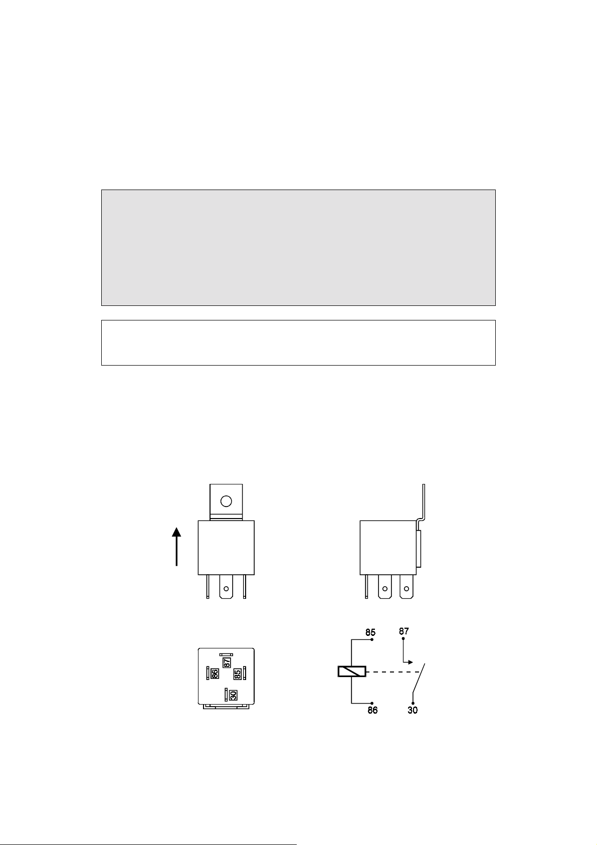
1.3.7. Power Relays
There is one relay used with the Haltech IG5, (the Main Power Relay)
It should be mounted on the firewall or an inner guard with the connector terminals to the
bottom as shown in the diagram.
14
Page 19

1.3.8. Electronic Control Unit (ECU)
The Haltech IG5 is not designed to be waterproof. It is desirable that the ECU be given as
much protection from the environment as possible. It is recommended that the ECU be
mounted inside the passenger compartment, either on the firewall, under the dashboard or
under the passenger seat.
The ECU has four mounting holes that allow it to be mounted to most flat surfaces. In
extreme cases of vibration, the ECU should be mounted on rubber anti-vibration pads. When
mounting the ECU remember that the communications connector on the loom should remain
accessible for ease of programming.
1.3.9. Flying Leads
Locate and connect the following flying leads.
Black - (Ground) Locate a good chassis ground point and connect the black wire. The best
spot is direct to the battery negative terminal.
Red - (Supply 12V) Locate a source of continuous 12 volts and connect the red wire.
Connecting direct to the positive battery terminal is suggested.
Grey - (Switched 12V) The grey wire is used to control the operation of the Haltech IG5
power relay. It needs to be connected so that it sees 12V only when the ignition is on
and during cranking. This wire does not draw a large amount of current (< 0.5A). Do
not connect to the accessory outputs of the ignition switch.
1.3.10. Install and connect any Optional Outputs
If you are planning to use any of the Programmable Optional Outputs, install and connect
them now. Depending on what options you are using, the wiring will be different. For details
on wiring your particular options, refer to Chapter 13, Auxiliary Outputs.
1.3.11 Connect the Trigger Sensor
Refer to Appendix C Trigger Inputs for detailed information on trigger connections. If the
engine has a magnetic reluctor type signal which requires a Reluctor Adaptor you should
install the Reluctor Adaptor now. For details on how to connect the Reluctor Adaptor to the
main loom and to the trigger refer to Appendix E Wiring Diagrams.
Hall Effect and Optical triggers have three connections - ground, power and signal. The
trigger connector on the Main Harness has four pins shown in the diagram below. The
Secondary (Home) Trigger is used for Direct Fire Applications. (See Appendix C.3).
15
Page 20

The secondary input can also be used as the Road Speed input if it is not being used as a home
trigger.
You will need to know what wiring your trigger requires. Some triggers need a series resistor
on the power line in order to limit current. Check your trigger system thoroughly. An
incorrectly wired trigger can cause damage, usually to the trigger.
The IG5 requires one trigger input signal per ignition event. For example, a V8 engine will
require 4 triggers per engine revolution. It is recommended that you read Appendix C,
Trigger Inputs for more detailed information on the trigger requirements of the IG5.
1.3.12 Connect the ECU
The ECU can now be connected. The system can now be tested as described in the following
chapters.
16
Page 21

CHAPTER 2 GETTING ONLINE
Now that your Haltech IG5 is installed with all the sensors in place the system can be
connected to the programming computer. This will allow the readings from all the sensors to
be displayed on the screen and checked for correct operation.
To connect the PC to the Haltech IG5 ECU you will need the programming cable and
programming disk supplied.
2.1 Connecting the Haltech IG5 to a Computer
The programming cable supplied with the Haltech IG5 is a standard serial link extension
cable. One end of the cable will plug into the Main Harness PC Interface connector (near the
main connector). The other end should plug into the mating connector at the back of your
computer. The plug on the computer may be marked "Serial", "Mouse" or "COM". Almost
all laptops will have this plug. If there is no 9 pin plug which it will connect to, check to see
if there is a 25 pin D-type plug available (some desk top computers will have this). If this is
the case, an appropriate cable can be supplied on request. Alternatively, most electronic
retailers will have a 25-pin to 9-pin converter.
Any time you wish to communicate with the IG5 ECU it needs to be supplied with power.
This usually involves just turning on the ignition switch. If at any stage power is not on, or
the programming cable is disconnected while attempting to communicate, the programming
software will display the message RECONNECT HALTECH. To rectify this, reconnect
power and/or the programming cable.
2.2 Operating the Software
2.2.1 Computer Requirements
The computer required to program the Haltech IG5 can be any IBM compatible personal
computer from the XT onwards (ie. the AT, 386, 486 or Pentium computers). The
requirements are fairly modest. The computer must have at least 640K of RAM (with about
615kb free for executable programs), one 3.5" disk drive and a CGA, EGA, or VGA screen.
(Virtually all reasonably modern laptops running MS-DOS (version 5.00 or higher) will fit
this description).
17
Page 22

2.2.2 Installing the Software
The Programming Disk supplied with the Haltech IG5 has an installation program that allows
you to install the software onto the PC’s Hard Disk. Most modern PCs have a hard disk. If
your PC does not have a hard disk, the IG5 Program can run directly from the disk supplied.
Installing the software on the Hard Disk will speed up program execution and avoid having to
fiddle around with floppy disks. The installation program needs only to be run once.
If you do not have a Hard Disk, go to the section titled Running the Software from the
Floppy Drive.
To install the software follow these steps.
Boot up Computer
Turn your PCs power on and boot up MS-DOS as instructed by the computers Users Manual.
If a shell program or menu utility runs automatically when you boot your computer, exit it
now. You should see a prompt similar to this:
C:\>_
This is the ‘DOS Prompt’. It is DOS’ way of indicating that it is waiting for a command. The
C: indicates that the C drive is the drive currently selected. If you do not have a hard disk,
your prompt will look similar to this:
A:\>_
Select the Drive
To run the INSTALL program, you must insert the supplied disk in the disk drive. To select
the appropriate disk drive (this will most probably be A: or B:) type:
The ←←←← key is the Enter Key. On some keyboards it may be called the Return key. You
should now see the prompt:
A:\>_ or B:\>_
Run the INSTALL Program
To run the Install program type:
α:←
or
ινσταλλ←
Β:←
18
Page 23

The Install program will now run. Follow the instructions given. The program will suggest
that the software will be placed in the HALTECH directory. You can change the destination
directory, but this is not recommended unless you understand how directories work.
When it is finished, the installation program will tell you if the installation is successful. If it
was not, consult the trouble shooting section of this manual.
The IG5 Program is now ready to run.
2.2.3 Running the Software from the Hard Disk
Boot up your computer as described earlier. If your computer is already on, make sure the C
drive is currently selected. To change to the HALTECH directory type:
or, if you used a different destination directory, type that path.
To start the program type:
The IG5 program will now run. The next section is on running the software from a floppy
drive. If you intend to run the program from the hard drive you can skip this section and go
straight to the section entitled Azerty Keyboards.
χ∆ ∴ηαλτεχη←
ιγ5←
2.2.4 Running the Software from the Floppy Disk.
To run the software from a floppy drive, boot up your computer as described earlier. Insert
the Programming disk in the disk drive. To select the appropriate disk drive (this will most
probably be A: or B:) type:
You should now see the prompt :
A:\>_ or B:\>_
To start the IG5 program type :
The IG5 program will now run.
α:←
or
ΙΓ5←
Β:←
19
Page 24

2.2.5 Azerty Keyboards
Most countries use a keyboard where the first six letter keys across the top row are :
This is called a Qwerty keyboard. Some countries use an alternative, which is called an
Azerty keyboard, where the Q and W keys are swapped with the A and Z keys respectively. If
you have an Azerty keyboard, you need to run the software slightly differently. When you
would normally type :
to run the programming software (not the installation software), you need to type:
The /A tells the program you have an Azerty keyboard. The program will adjust accordingly.
θωερτψ
ΙΓ5←
ΙΓ5/α←
2.3 The Online and Offline Modes
On the IG5 system title page, the software asks whether to operate in ONLINE or OFFLINE
mode. The Offline mode is very useful to familiarise yourself with the Haltech software, but
should not be used to make lasting adjustments to the ignition maps unless there is a special
reason for doing so. If you wish to experiment and familiarise yourself with the software
press N for Offline mode, but if the ECU is installed and power is available then we suggest
the Online mode be selected. Press Y to select online mode.
2.4 Using the System Online
In the Online mode there is a two-way flow of information between the ECU and the
programming computer. The communication cable must be installed and power must be
available to the ECU before the system can communicate. The Online mode will be used
most frequently. While using the system Online, you can view engine information directly
and make adjustments. Any changes or modifications made on the computer are
instantaneous and will be immediately recorded in the ECU. When the programming cable is
removed and the ignition switched off, the ECU will retain all of its memory. The maps do
not need to be saved, but keeping a copy on disk is always good practice and is recommended.
Note: If power is removed or the communication cable is disconnected or
interfered with, the following message will be displayed on the computer
screen.
RECONNECT HALTECH
20
Page 25

If this message appears check all connections and ensure that the communications cable is not
being interfered with. Also be sure that the Haltech IG5 unit is receiving power. (i.e. ignition
switch is turned "on".)
2.5 The Main Menu
When you select Online or Offline mode the Haltech MAIN MENU bar appears. This menu
bar allows access to sub-menus giving access to maps, file storage/retrieval, engine data and
options.
2.6 How to Quit
Throughout the program you can exit from any application by using the menu bars or hot
♣θ
keys. Pressing
♣θ
in any page will prompt you to exit the program (i.e. pressing
♣θ♣θ
θθθθ
while
holding down the
♣♣♣♣
key). If you wish to exit press
ΨΨΨΨ
when prompted.
2.7 Checking the Engine Data
The engine data option can only be used when the system is Online. This function allows all
of the engine data variables to be displayed on the screen
This is a very useful function for analysing the engine sensors. To display the engine data
♣ε
♣ε
press
pressing
Do not attempt start the engine if the Engine Identification has not been set up. View the
engine data page to ensure all the sensors are operating properly.
from any application. Alternatively it can be accessed through the menu bar by
♣ε♣ε
ƒΟ
ƒΟ
and then
ƒΟƒΟ
ΕΕΕΕ
for Engine Data.
21
Page 26

CHAPTER 3 ENGINE IDENTIFICATION
3.1 Setting Engine Identification
The Identification page tells the IG5 information about the engine characteristics. Without
this information being correct the engine cannot run properly. The Identification is made up
of several fields. Each field can have a number of settings, and you can change most of the
fields.
′′′′
Use the Up and Down arrow keys (
Selection type, or Text type. The Selection type fields give you a number of valid entries for
that field. For example, the valid number of cylinders can be set to 1, 2, 3, 4, 5, 6, 8, 10 or 12.
and
≤≤≤≤
) to move between fields. The fields are either
The Tab and Enter keys (
the Tab key will display the next selection. The Shift and Tab keys together will step
backwards through the selections. Once the desired selection is displayed, the Enter key is
pressed to program that selection. Text Fields require you to enter either text or numbers.
Once the field is selected, the new text can be typed in, with the Enter key to finish. An
example is the Rev Limit. This field can be set between 2000 and 16000 rpm. If you want the
rev limit to occur at 7000rpm, then you would need to select this field using
7000←
7000←
type
7000←7000←
Here is a description of each of the Identification fields:
Cylinders
Load Sensing
MAP Sensor
RPM Limit
.
The number of engine cylinders needs to be entered here. This parameter is used to
determine the engine speed.
The IG5 can use either the manifold pressure or the throttle position as a means of
determining the engine load. Most engines operate using manifold pressure to sense
engine load. If your engine employs any form of supercharging, you must run in
manifold pressure mode. Only wild cams, motorbikes or heavily ported rotaries
require throttle mode – i.e. engines whose vacuum signal is small, or fluctuates
greatly. If you are unsure what to use, contact your Haltech dealer.
The IG5 needs to know the pressure range of Manifold Absolute Pressure (MAP)
sensor being used. Refer to Chapter 1 [1.3.1]. The selected value can be 1, 2 or 3bars.
The IG5 can limit the maximum rpm at which the engine will operate. Above this
level the IG5 completely cuts ignition to the engine. When the engine speed drops
below the RPM Limit the IG5 will resume normal ignition delivery. This is known as
hard limiting. If the RPM Limit is not wanted then set this value above the highest
operating point of the engine.
♥♥♥♥
and
←←←←
) keys are used to change this type of field. Each stroke of
′′′′
≤≤≤≤
or
and then
22
Page 27

Units
The Haltech IG5 programming software can display parameters in either Metric or US
units.
RPM Mode
The IG5 ignition maps may be arranged either in 500 rpm increments to 10,500 rpm,
or in 1000 rpm increments to 16,000 rpm. Select the high - or low - rpm mode here.
Changing settings alters the way the ECU reads the Maps, and will change the tuning
of the engine dramatically. Do not change this setting once tuned.
Road Speed Value
This value calibrates the Road Speed reading. Some configurations cannot use the
Road Speed input trigger in which case this field will not be displayed.
Trim Control
The optional Trim unit can be used to control one of several parameters. This field
selects the controlled parameter. If there is nothing connected to the trim plug, the
trim will have no effect (except with boost control). The available functions are :
Ignition +7 to -8 degrees adjustment of ignition advance.
Ign Trailing +7 to -8° adjustment for Rotaries only
Boost Control Boost trim for Wastegate control only.
Aux. In Function
The Auxiliary Input on the IG5 can be configured for one of a number of functions.
Most of these functions relate to the configuration of the system. The available
functions are:
Disabled No effect on ECU operation.
Nos Input Input - This input is used in conjunction with the
Nos Optional Output. [13.10]
TCC Input Input - This input is used in conjunction with the
TCC Optional Output. [13.4]
Turbo Timer Input - This input is used in conjunction with the
Turbo Timer Optional Output. [13.9]
Since the Auxiliary Input line can only perform one duty, all of the above functions are
mutually exclusive, i.e. although four programmable outputs exist on the IG5, only one of the
NOS, TCC and Turbo Timer may be chosen. Keep this function in mind when deciding on
the IG5 configuration you wish to run.
3.2 Ignition Set-up
The Ignition Set-up works in an similar way to Engine Identification. Its fields relate to the
way the ignition advance is determined for the engine. Enter the Ignition Set-up by pressing
ƒσ
ƒσ
ƒσƒσ
then
ΙΙΙΙ
. The fields in the Ignition Set-up are:
23
Page 28

Trigger Degrees
This field tells the ECU where to expect the Main Trigger to occur. This field is very
important for the correct operation of the ignition. If it is incorrect, the spark advance
will also be incorrect, which could lead to engine damage. The ECU needs to receive
an input trigger at a fixed engine angle Before Top Dead Center (BTDC) for each
spark. This trigger may be set between 60° and 100° BTDC. See Chapter 5 for
details.
Lock Timing at 10 Degrees
This field is used for testing the trigger input. It allows the timing to be locked at ten
degrees regardless of the engine speed and ignores the ignition map settings. This
feature is further discussed in Appendix C
Trigger Edge
This field determines whether the IG5 is to trigger on a rising or a falling edge. Refer
to Appendix C - Trigger Interface for details on how to determine this setting. If a
Reluctor Adaptor is being used, this field should be set to Falling.
Output Type
This field is used to determine how the ignition output signal is to be defined.
Constant Duty should only be used with the Bosch type Haltech Ignition Module or
other “intelligent” igniters and special after market systems that perform dwell control.
Constant Charge may be selected if the igniter operates simply as a switch (ie a
“dumb” igniter) and requires a dwell signal.
INCORRECTLY SETTING THIS FIELD WILL CAUSE FAULTY
OPERATION AND MAY BURN OUT THE IGNITER(S). DAMAGE
CAUSED BY INCORRECT SETTING WILL NOT BE REGARDED AS
Coil Charge Time
Only required if Constant Charge selected as Output Type. This is the time require to
charge the coil fully, or until the igniter’s current limit is reached, typically 4-5 ms.
Refer to Appendix B for additional information.
Output Edge
The Output Edge should be falling with a 30% switch when using a Bosch igniter (the
EB023 supplied by Haltech). This is the default setting. If you are using any other
igniter, refer to Appendix B for details on how to set this field for the igniter used.
Trigger Type
This field defines the trigger pattern the ECU will see coming from the crank or cam
angle sensors. The IG5 currently supports the following trigger types:
Standard This trigger pattern sends one trigger for each spark event. For example a
V8 has 4 firing strokes for each crank revolution, for this engine the ECU would
expect to see 4 trigger events for each crank revolution or 8 events for each cam
revolution.
WARNING:
WARRANTY.
24
Page 29

Multi-tooth This trigger pattern is the same as that for the Standard Trigger except that
there are multiple trigger events for each spark event. The number of teeth for a
multitooth trigger must be a multiple of the spark events. This trigger requires a home
signal for synchronisation of the trigger and engine position.
Motronic This trigger is a variation of the multitooth trigger pattern. This setting is
compatible with the BOSCH Motronic controlled engines. The Motronic wheel has
multiple teeth with a set number of teeth missing for synchronization removing the
need for a separate home signal. The BOSCH Motronic wheel usually has 60 teeth
positions with 58 teeth and 2 missing teeth.
Twin Trigger This trigger is used in conjunction with twin distributor ignition
systems. Since it is a distributed system there is no requirement for a home signal so
this channel is used to carry the second trigger.
Number of Teeth
This field is only applicable if the trigger type is Multitooth or Motronic. The Number
of teeth:
Multitooth The number of teeth on the multitooth wheel
Motronic The number of teeth on the motronic wheel including the missing teeth
Tooth Offset
This field is only applicable if the trigger type is Multitooth or Motronic. The offset is
the number of teeth the synchronisation event occurs prior to the trigger
Home Edge
This field is similar to Trigger Edge it defines the active edge for the Home channel.
If a reluctor adaptor is being used this field should be set to falling.
Spark Mode
This field defines the ignition delivery used, the options are: Distributor, Direct Fire or
Twin Distributor.
Coils on 4-cylinder motor
This field is only applicable if the spark mode is Direct Fire and the number of
cylinders in the main set-up is “4”. The options for this field are: “2” or “4”. If “2”
is selected waste spark is used. If “4” is selected there is one coil for each cylinder.
Engine Type
This field defines the engine type: Piston or Rotary.
25
Page 30

CHAPTER 4 USING HALTECH SOFTWARE
The tutorials presented in this chapter are examples of how to use the Haltech software.
They assume that you have the software running online on your PC, with the ECU powered
and connected via the supplied programming cable.
4.1 Using the Software
In order to make the software easy to use, the program presents you with a menus bar at the
top of the display. The menu bar is accessed through simple combinations of key strokes.
Once the appropriate menu has been accessed a sub-menu appears with the headings of the
available pages.
4.2 What is mapping the Engine?
Mapping the engine is filling in the look-up tables with the correct values for your engine.
This is done by adjusting the heights of bars in bar maps. Bars may be adjusted one at a
time, or in groups. The Haltech programming software has been designed to make engine
mapping as simple and intuitive as possible.
4.3 What are maps?
Ignition Maps
The ignition advance needed by the engine under different speed and load conditions are
stored in the IG5 in a look-up table called the Ignition Map. The IG5 uses the engine's load
and speed as an index to the table. For instance, at an engine speed of 4000 rpm and a
manifold pressure of -20kPa the relevant number in the table may be 35. When the engine is
running at 4000 rpm and -20kPa manifold pressure the computer will extract the value of 35
from the table and fire the ignition at 35 degrees. This value may be modified slightly by
other correctional maps also under user control which are described later. The programming
software divides the table into rpm range maps. Within each rpm range map there are 32
load points along the horizontal axis, each represented by a vertical bar. The greater the
vertical height of the bar, the greater the ignition advance. The load points usually represent
incremental changes in intake-manifold pressure but may, for certain engine types, be set up
by the user to represent changing throttle positions. When you view a Map (see section
4.3.1) you see a bar chart of ignition time versus load for all the load points in that particular
speed range.
Other maps
There are other tables in the IG5 which are also called maps. They are indexed by only one
parameter and so are not divided into ranges and are described later..
26
Page 31

4.4 Accessing the Ignition Maps
ĵ
Pressing
Ignition maps. Or you can access the ignition maps directly through
application.
ĵ
from any page will take you to the Maps Menu. From here you choose
ĵĵ
4.5 The Ignition Maps
ΙΙΙΙ
for the
♣Ι
♣Ι
from any other
♣Ι♣Ι
The ignition map shown above is explained in detail here.
The Menu Bar
This has the names of four major software menus embedded in it. Any of these may
be accessed by holding down the Alt key of the PC keyboard and pressing the initial
of the required group
Range 1
This range information (in a box - top left) refers to the bar graph map currently
displayed . The rpm beneath it will depend on the rpm mode previously selected on
the Engine Identification page. The displayed map range is selected by either the F
keys along the top of the keyboard or from the Ignition Map.
Engine Data
This is displayed across the bottom of the page is the live data of the running engine
when the system is in the “on-line” mode
27
Page 32

Range 3 Bar 13
This information refers to the instantaneous engine speed and load and will follow any
changes in these values.
°Advance
This is the vertical axis of the ignition maps and indicates the advance selected for the
relevant engine speed and load.
-100 to 100 kPa
This is the horizontal axis of the ignition maps and indicates load range at the current
engine speed (defined by Range X). This particular map is used in conjunction with a
turbo-charged engine operating up to 1 bar of boost.
Highlighted bar
In the example above this is the bar above 0 kPa. It is the bar that will be altered in
height if the up or down arrows are pressed (see next section).
Arrow above bar
If the displayed map is in the same speed range as that at which the engine is actually
running, an inverted triangle will display above the vertical bar corresponding to the
actual load point of the engine. This is very useful when running an engine on a dyno
and you want to see what effect a change in ignition advance will have. The current
map can be accessed through the Ignition Map selection display by pressing the Home
key.
4.6 Altering a Map
ƒξ
Note: When two keys are displayed together, such as
second key must be pressed while the first key is held down. In this case, the
key would be held down while the
The height of the Bars in the map can be adjusted by using the up and down arrow keys for
small changes of the PgUp and PgDn keys (
summary at the end of this section for a full list of key functions. The bar that is highlighted
on the computer screen indicates the bar that you are adjusting. To select a different bar, use
the left and right arrow keys (
bottom of the display.
The ignition advance displayed does not necessarily match the bar height shown on the on
the map rather it is the final ignition advance after the various corrections have been made.
The ignition advance displayed in the engine data is indicated by the arrow above the
applicable bar, this is not necessarily the highlighted bar.
Changes made take effect the instant the keys are pressed. You do not have to do anything
else to save these changes.
∞∞∞∞ ⁄⁄⁄⁄
). The ignition advance for the outlined bar is shown at the
≥≥≥≥ ××××
) for larger increments. See the command
ƒξ
, this means that the
ƒξƒξ
ξξξξ
key is pressed.
ƒƒƒƒ
28
Page 33

It is possible to program the IG5 numerically. To enter the numeric mode press
spreadsheet of ignition advance data versus engine load and speed will appear. Use the
arrow keys to navigate the spreadsheet by moving the highlighted cursor to the required
field. Changes can be made by typing the ignition advance as a decimal number
representing degrees of advance (°BTDC). The whole spreadsheet is too large to display all
at once and the remainder can be accessed by using the arrow keys to shift the spreadsheet to
the left or right.
To return to the standard bar graph mode by hitting the ESC key. This method of mapping
can be extremely time consuming so the Haltech allows you to change the numbers by
manipulating maps presented as bar graphs which is much simpler and allows you to
visualize the result.
ƒƒƒƒνννν
. A
4.7 How To Quit
♣θ
Pressing
you to MS-DOS. You should always exit the program before switching off your computer.
The best way to initialize the Ignition Map is to use the Library Maps, and then return to the
Ignition Map later if the ignition curve needs modification. Ignition Library Maps are
explained in Chapter 5 [5.4], Starting the Engine.
♣θ
at any page or map will allow you to exit the Haltech program and will return
♣θ♣θ
4.8 Time Saving Functions
The following is a list of commands that can be used when the ignition maps are displayed.
These commands provide easy access to specific areas of the maps during tuning.
4.8.1 Current Location
Pressing
is currently being used. This bar is easily identified by the arrow above it pointing down. As
the engine speed and load changes, the arrow moves with it. The Home key can be used to
find the engine's operating point quickly.
″″″″
will take you to the range at which the engine is running, and highlight the bar that
4.8.2 All Ranges
ƒρ
The All Ranges function allows the user to initialize all RPM ranges with the same data.
enables the All Ranges function and “All Ranges” will appear under the title.
When the All Ranges function is active, a bar adjusted on one graph is copied to the same bar
on all the ranges. If you use this option, you can set the shape of the map at any range, and all
other ranges will be identical at every bar you adjusted. This feature enables all graphs to be
given an initial shape that should run the engine, albeit rather roughly. Once you have used
ƒρ
ƒρƒρ
29
Page 34

ƒρ
the All Ranges option for a starting point, press
and tailor each map individually.
This option is only available on the Base Ignition Maps.
ƒρ
once more to exit the All Ranges option
ƒρƒρ
4.8.3 Selecting Groups of Bars
Groups of adjacent bars may be highlighted and adjusted together.
♣♣♣♣
Hold
This group will now act in unison when increasing or decreasing the height of the Bars. To
deselect the highlighted Bars use the
while using the left or right arrow keys,
ƒƒƒƒ
and arrow keys together.
∞∞∞∞ ⁄⁄⁄⁄
, and you will highlight a group of bars.
4.8.4 Percentage Changes
Using this function will prompt you to enter a percentage change to the selected bars. An
entry of "20" will increase each bar by 20%, while an entry of "-15" will decrease the bars by
15%. This change only affects the highlighted bar(s).
4.8.5 Linearise
When a group of bars is selected (more than two), this function can be used to set the values
between the end points. Highlight the bars between two load points that are known to be
ƒλ
correct and press
between the two end points to form a straight line. This feature facilitates fast programming
and the smoothing of maps.
ƒλ
. The programming software will automatically adjust all the bars
ƒλƒλ
4.8.6 Numeric Mode
This will take you into numerical mode, displaying the map as a spreadsheet. This mode is
available if wanted, but graphical mapping is recommended as it is much easier to use. To
exit from Numeric Mode and go back to using the maps press the
°°°°
key.
4.8.7 Bar Increments
The Up and Down arrows,
determined amount, usually the smallest possible increment. PgUp and PgDn also change the
bars by a pre-determined amount. These increments (the value of the keystroke) can be
ƒι
changed by the user.
particular keys can be changed.
ƒι
ƒιƒι
≤≤≤≤ ′′′′
, normally change the bar height in the maps by a pre-
will bring you to a screen where the increments associated with
30
Page 35

Normally, the bars are altered by adding or subtracting a fixed amount. The adjustment keys
ƒπ
may instead apply a percentage change on each keystroke.
♣φ
will switch to percentage increments,
ƒλ
ƒλ
will space out increments evenly between the Up/Down Arrows field and the Ctrl
ƒλƒλ
PgUp/PgDn field.
♣φ
will return you to fixed increments.
♣φ♣φ
ƒπ
on the Bar Increment Screen
ƒπƒπ
4.8.8 Online Help
♣Η
The current version of software offers the “help shortcut key”:
is not available. Please refer to your manual for help with aspects of installation and
operation of your Haltech system.
♣Η
unfortunately this feature
♣Η♣Η
31
Page 36

4.9 Command Summary for Maps
,
- move left/right highlighted bar(s)
∞∞∞∞
⁄⁄⁄⁄
,
- increase/decrease highlighted bar(s)
≤≤≤≤
′′′′
,
≥≥≥≥
♦≥
♦≥
♦≥♦≥
♦×
♦×
♦×♦×
♣≥
♣≥
♣≥♣≥
- increase/decrease highlighted bar(s)
××××
,
- increase/decrease highlighted bar(s)
,
♣×
♣×
♣×♣×
♣⁄
♣⁄
♣⁄♣⁄
♣∞
♣∞
♣∞♣∞
ƒ⁄
ƒ⁄
ƒ⁄ƒ⁄
İ
İ
İİ
ƒΠ
ƒΠ
ƒΠƒΠ
ƒΛ
ƒΛ
ƒΛƒΛ
ƒΙ
ƒΙ
ƒΙƒΙ
ƒΝ
ƒΝ
ƒΝƒΝ
ƒΡ
ƒΡ
ƒΡƒΡ
ΝΝΝΝ
- increase/decrease highlighted bar(s)
,
- select (highlight) next bar
,
- deselect end bar
- enter Percentage change to highlighted bars
- Linearise between end points of highlighted bars
- set Increments
- enter Numeric mode
- toggle All Ranges mode
- move to Next range
- move to Previous range
ΠΠΠΠ
ϑϑϑϑ
- jump to range of value entered
- go to current engine range/bar
″″″″
- switches option in setup pages
♥♥♥♥
32
Page 37

CHAPTER 5 STARTING THE ENGINE
There are a few things that need to be done before starting the engine. Make sure that the
ECU is powered (ignition on) and the Haltech Software is Online. Go to the Engine Data
Page to check that the ECU is communicating properly, and that all sensors are reading
correctly. Check again that the Identification and the Ignition Set-up are correct.
5.1 Calibrate the Throttle Position Sensor
The throttle sensor must be calibrated so that the ECU knows the start and stop positions of
the sensor. Choose the "calibrate throttle" option from the options menu and follow the
instructions on the screen. Set the idle throttle opening using the idle adjust screw. If the
required opening for idle is not known, make an estimate but keep in mind that this may be
the reason for poor idle later on, and further adjustment may be needed.
5.2 Check the trigger signal
It is a good idea to check that the IG5 is receiving a reliable trigger signal by cranking the
engine over on the starter. The rpm displayed on the engine data page should read about 100
to 300 rpm. If the engine speed is zero or is erratic then refer to the section in Chapter 1
[1.3.11] regarding trigger setup. If the trigger is operating correctly then continue.
5.3 Check the Base Timing
The IG5 uses the trigger input signal taken from either the cam angle sensor or flywheel
sensor for its base timing. To ensure that this base timing is set correctly the IG5 has a
TIMING CHECK FLAG which, when set to “on” will cause the IG5 to fire the ignition at
10° before TDC regardless of engine speed or load, if the trigger angle setting is correct.
ƒσ
To enable this flag, press
keys move to the Timing Lock option. If it reads Timing Check On, the flag is enabled. If it
reads Timing Check Off , then the flag is disabled. The flag is toggled by pressing
Timing Check is on, the ECU will lock the timing to where it believes 10° advance to be.
Check the base timing by cranking the engine with the Timing Check on. Use an ignition
timing light to check that the ignition timing is set to 10° BTDC. See the workshop manual
for your engine for details on checking ignition timing and the use of a timing light. It is
suggested that you remove the fuse for the fuel pump and do the timing check while cranking.
This will require two people - one to crank the engine and one to operate the timing light. It
can be difficult to check the timing accurately at cranking speeds. Removing the spark plugs
will help the engine to rotate at an even speed. Once you have checked the timing at crank,
leave the Timing Check on.
If the timing light does not show 10° BTDC the ECU is not being triggered at the same angle
as that specified in the Trigger Degrees field in the Ignition Setup. If the timing is out go
ƒσ
from the Sub-Menu select the Ignition Setup. Using the arrow
ƒσƒσ
♥♥♥♥
. If the
33
Page 38

back and check all the angles again. If you have guessed the trigger angle, try and calculate it
properly. Remember that the angle is in crankshaft degrees, not distributor degrees. Also
make sure the correct trigger edge is selected (rising or falling).
If the angle is a little out alter the angle in the Trigger Degrees field. If the correct timing
lies outside the 60° to 100° range permitted in this field, mechanical changes will have to be
made to the trigger set-up. If timing reference is taken from a distributor, then you may be
able to rotate it while using the timing light until the engine is at 10° BTDC. Be wary about
adjusting the base timing in this manner by any more than a few degrees as it can upset the
rotor phasing. For details on rotor phasing, see Appendix D.
When the base timing is verified as correct with the timing check “on” the engine may be
started. You must now ensure that the timing does not move as the engine speed changes.
Give the engine a few quick revs while using the timing light to check that the ignition timing
stays at 10° BTDC. If the base timing is locked at 10° BTDC and does not change with
engine speed then you are ready to load an Ignition Timing Map and turn off the Timing
Check Flag.
If the ignition does change with engine speed then see the Troubleshooting procedure in
Appendix A
5.4 Loading an Ignition Library Map
The IG5 has an effective and time saving method of programming the ignition curve using
Library Maps. Each ignition timing Map in the library is slightly different. By becoming
familiar with the library you should be able to select an ignition timing Map that will suit your
engine. Each ignition timing Map in the library is accessed by a different name. The name
reflects the characteristics of the Map. Names can be up to eight alphabetic or numeric
characters in length. The ignition timing library Maps use these eight characters as shown,
where the first character is always a number.
• The first two characters in the ignition timing Map name specify the ignition timing to
be used at idle. The example Map name shown has 15 degrees of advance at idle.
34
Page 39

• The third character in the ignition timing Map name specifies the Rpm at which
maximum advance occurs (ie.. how quickly advance changes with engine speed). This
character is a letter of the alphabet. Option A has full advance in by 1500 Rpm. Option
B has full advance in by 2000 Rpm. Option C at 2500, etc. up to J for 6000 Rpm.
• The fourth and fifth characters in the ignition timing Map name specifies the maximum
advance at atmospheric pressure. Cruise or light load advance is added to this value,
while retard on boost for turbocharged or supercharged engines is subtracted from it.
• The sixth character in the ignition timing Map name specifies the extra ignition advance
to use at light loads such as highway cruise. This is equivalent to the vacuum advance
on a distributor. If this character is A, there is no extra advance under light load. Each
successive letter of the alphabet after A adds 3 degrees of ignition advance to the full
load advance under light load, up to the letter H. (H = 21°)
• If the engine is turbocharged or supercharged then the seventh and eighth characters
specify the ignition retard the engine is to get under boost. This value is subtracted from
the atmospheric pressure advance value. If the engine is not turbocharged or
supercharged, then leave the name only six characters in length.
A description of each parameter is displayed on the Library Maps page to save you referring to
this manual.
As mentioned above, it is suggested that the timing be checked before starting the engine. If the
ECU successfully locks the timing at 10° then you should load a library map that will get the
engine started. Try be conservative. You should not be looking to gain the last few percent in
performance immediately. If you know the factory settings for idle, vacuum and full load
advance for your engine you can use those values to load an extremely effective Library Map.
5.4.1 On the Dyno
Whether the vehicle is on a chassis dyno, or the engine on an engine dyno, the principles of
programming the Haltech IG5 are the same. The quick map feature mentioned previously is a
great starting point and should allow the motor to start and run.
Take the engine rpm up to 1000 and apply partial load and adjust the 1000 rpm range. Now
keep an eye on the dyno readings and adjust the ignition curve appropriately to achieve
maximum gains. Continue, adding more load, up to the full load settings. Repeat this for the
rest of the ranges.
Full load tuning should be approached with caution. An engine at full load that is over advanced
may begin to detonate and destroy pistons and crankshafts. Before loading the engine, decrease
the heights of the right most bars so that they are lower than the line projected by drawing a
straight line from the idle and free-rev settings and through the part-load settings.
35
Page 40

5.4.2 On the Road
Tuning on the road is similar to tuning on the dynamometer, but with hills, acceleration, gearratios and brakes providing the necessary retarding force. Although it is harder to maintain
constant load and speed, it is still possible to use the same procedure used on the dyno. It will
be necessary to have one person drive while another does the tuning.
Load the engine by selecting an appropriate gear and either driving up a constant grade hill,
applying the brake or handbrake.
WARNING:
BE VERY CAREFUL USING THE BRAKE TO LOAD THE ENGINE.
THE BRAKES CAN GET VERY HOT AND SUFFER FROM BRAKE
FADE (REDUCED BRAKING CAPABILITY) AND THE CARS
HANDLING MAY BECOME UNSTABLE. ALL ROAD TESTING
SHOULD BE DONE AT LOW SPEED.
36
Page 41

SECTION 2 Other Adjustable Features
CHAPTER 6 COLD STARTING AND RUNNING
The Haltech IG5 has two features to modify ignition timing to aid in starting and running a
cold engine.
The Ignition Crank Map defines the ignition advance at different coolant temperatures during
cranking. The Ignition Coolant Map corrects the base ignition timing by advancing or
retarding the ignition at different coolant temperatures.
6.1 Cold Cranking
The ignition timing can be set for cold cranking. The Crank Ignition Map sets the ignition
timing to be used while cranking according to the coolant temperature. This Map is set flat to
15° at factory, but it can be adjusted to give better starting at all temperatures.
37
Page 42

CHAPTER 7 CORRECTION FACTORS
The Haltech IG5 has correction maps to adjust ignition timing for coolant and inlet air
temperatures. These maps are set to provide a base correction for almost all engines.
7.1 The Ignition Coolant Map
The Ignition Coolant Map allows up to 10° advance or retard of the spark timing based on
engine coolant temperature. This Map should only be used if there is a need to adjust the
timing for low or high temperatures.
7.2 The Ignition Inlet Air Temperature Map
This Map allows up to 10° advance or retard of the spark timing based on the inlet air
temperature. Normally this Map would not need to be used, but in some cases such as high
inlet air temperatures on turbo/supercharged engine, retarding the spark may help preserve the
engine.
38
Page 43

SECTION 3 Software Features
CHAPTER 8 FILE STORAGE AND RETRIEVAL
Once your Haltech IG5 system is configured you should store the entire set of maps and the
Identification to disk. In fact, it is wise to save maps regularly during tuning so that you can
return to a known map while you are experimenting in different areas. You can use the file
storage and retrieval to enhance the flexibility of your race engine by storing the optimum
maps for each race track.
ƒφ
The File storage and retrieval functions can be accessed from the Main Menu by pressing
for files. This function allows you to load engine maps and identification from computer disk.
You can also save the engine maps and the identification to computer disk.
8.1 Saving Maps and Identification
ƒφ
ƒφƒφ
8.1.1 The Save Command
To store all the maps and identification to computer disk with the system running Online,
press ƒφ then Σ at the Files sub-menu. The list of maps already stored will appear on the
screen.
You can save maps that you have generated Offline to later be loaded into the ECU. You can
also save different versions of a map to save time while tuning track-side. You can even have
different maps for different circuits.
8.1.2 Giving Your Map A Filename
Choose a name to identify your saved file. If you choose the same name as a map that has
already been saved, the old file will be overwritten and replaced with the file you are currently
saving with the same name. If you do not wish to erase any files already saved, choose a new
filename - one that does not appear on the screen.
The name you choose should not include any spaces or full stops and can be up to eight
characters in length. The name must start with a letter from the alphabet, not a number. For
the sake of your own memory, try to select a name that you will be able to recognise in six
months time.
As you perfect the maps for a particular application you might add a number to the end of the
name to indicate which map is most recent. For example you might call the maps for a Turbo,
Turbo1, Turbo2, etc.
After you have chosen a name for the maps, you must enter the name in the space provided.
The system will pause and ask if it is OK to continue with the save. If everything looks
39
Page 44

correct, continue by pressing
ΝΝΝΝ
by pressing
ΡΡΡΡ
, or
to re-enter a name.
ΨΨΨΨ
. If you entered the name incorrectly, abort the Save function
8.2 Loading Maps and Identification
While the ECU system is Online, you can load previously saved map information from
computer disk into your Haltech ECU. The contents of the ECU are erased and replaced with
the new maps you have chosen. If you are Offline, you can load previously stored maps, view
and edit them, then save them for later use.
To load new complete maps and identification into the ECU, you must first be Online. Press
ƒφ
ƒφ
ƒφƒφ
replaces it with the set of maps stored on the disk you are loading into the system.
Although the loading of the maps should not affect the running of the ECU, it is best that the
engine is not under load while maps are being loaded.
Select the name of the map you wish to load by using the arrow keys to highlight that name
and press return. If there are more files then will fit in the window, you can scroll down
through the extra files using the arrow keys. If you know the name of the file, you may type it
in. The computer will then pause to ask if everything is OK before continuing the load. If
λλλλ
then
from the Files sub-menu. The load command erases the contents of the ECU and
Note: Remember to save any maps currently in the ECU that you wish to retain
before loading new maps from a disk.
you are ready to proceed, press
take approximately two minutes.
ΨΨΨΨ
. If there is an error, abort by pressing
ΝΝΝΝ
. The load will
8.3 File Management
The ECU's map information is stored as a file on disk. You may think of these files as books
in library, where the filename is the title of the book. So that the books do not become
difficult to find as your library grows, there are a few features that help you to organise your
files.
8.3.1 Erasing Unwanted Maps
The Erase function in the Files sub-menu will delete old files from disk. Press
Files sub-menu to enter this function. The list of maps stored on the disk will appear. Use the
Up and Down Arrows to select the map you wish to erase, or else type in the name of the map,
then press return (
continue to erase, or else
←←←←
). The computer will pause to check that everything is OK. Press
ΝΝΝΝ
to abort.
ΕΕΕΕ
from the
ΨΨΨΨ
to
40
Page 45

It is a good idea to erase old maps as soon as they become obsolete. This is particularly true if
you are trying to build a library of maps. It can become difficult to remember later which
maps are current and which are obsolete.
8.3.2 Changing Directories
If files can be likened to books in the library, then directories are analogous to names on the
shelves. Directories can be used to group related files together.
ƒχ
To change directories when loading, saving or erasing maps, press
now display all directories in square brackets. Select the directory you want using the Up and
Down arrows, and pressing Return. Directories can exist within other directories, so you may
ƒχ
. The Files List will
ƒχƒχ
change several times before reaching the directory you seek. Once you have found it, hit
The symbol [..] indicates the parent directory to the one you are in.
°°°°
.
41
Page 46

CHAPTER 9 PRINTING MAPS
9.1 The Print Function
You can print the maps and identification information to printers that accept IBM emulation
mode, such as IBM compatible dot matrix, inkjet or laser printers, (consult your printer
manual). The Print function should work with other printers, but some special characters such
←←←←
ππππ
from the Options
).
as °, ±, etc. may not print correctly. Select the print function by pressing
sub-menu
The system will present you with options on which data you wish to print. There are four
options. Their meaning is as follows:
1) Setup Information - this will print only the setup pages (ie. Main and Ignition pages).
2) Maps - Prints all the maps in the system (ie. Ignition and Coolant).
3) Output Options - This function will print the current settings and the status of the output
options of the ECU. (ie. Turbo Wastegate).
4) Print All Information - This will print all of the above information
The system will ask for a name to print at the top of the printed output. This allows you to
differentiate between printouts if you have printed more than one set of maps. The name can
be up to ten characters in length. Type in the name and press Enter (
The system pauses to allow you to set up the printer. If you do not want to print you can leave
the print function by pressing
printing the printer must be Online and must have power and paper. Once the printing has
started you can abort the printing by pressing
°°°°
. Pressing any other key starts the printing. Before you start
°°°°
.
42
Page 47

CHAPTER 10 DATALOG
10.1 The Data-log Option
This option records the Engine Data information at a nominal rate of 10 samples per second
while the engine is running. This data-log is useful for tracking the system's behaviour
through changing rpm. It also facilitates trouble-shooting, as all the ECU's working
parameters are recorded faster than they can be read on the Engine Data Page.
ƒο
The Datalog Menu is accessed through the Options Menu. (Press
to make a datalog, the IBM software must be running and Online. Or it can be accessed
♣∆
directly by using
♣∆
♣∆♣∆
ƒο
). Then select the
ƒοƒο
∆
∆
∆ ∆
key
10.1.1 Setting Up the Data-log Page
Before beginning a data-log the data page can only display eight parameters which are
selectable through a simple menu. To access the configuration menu press
instructions that are presented with the selection menu.
ΧΧΧΧ
and follow the
10.1.2 Creating a Data-log
You can choose to record the datalog either in memory or directly to disk. To record to
memory, press
up to about three minutes ie.. when you stop the datalog, it has a record of the previous three
minutes of engine data.
Alternatively, you can datalog directly to disk by pressing
enter a filename. When recording to disk, you are limited only by the free space left on disk.
The datalog consumes about 11kbytes per minute of running. The disk supplied has over 20
minutes of datalog space. The disadvantage of datalogging in this manner is that there will be
small gaps in the datalog of a few seconds as a block of information is written to disk. If
datalogging to hard disk, these gaps become insignificant.
You should save the Maps being used at the time of the Datalog to disk. It is advised to do
this before the Datalog is taken. Saving the Maps makes sure that all the engine information
(including the Identification and the setups) are saved to disk. If the Datalog is view offline at
a later date, the Maps will need to be loaded so that the programming software knows the
setup of the ECU and can interpret the data properly.
To stop the datalog press . If you are performing a datalog to memory, the screen will
instantly jump back to the Datalog sub-menu. If you have been recording to disk, there will
be a moment's pause as the file is closed.
∆∆∆∆
in the Datalog sub-menu. This will record engine data in a continuous loop,
ΑΑΑΑ
. The software will ask you to
43
Page 48

10.1.3 Viewing the Datalog
To view the datalog you have just taken, press
Data information will appear as rows across the screen, with a time index at the end of the
row.
At the bottom of the screen is a list of the command keys. They are described in detail here:
- scroll up datalog one line
≤≤≤≤
- scroll down datalog one line
′′′′
- scroll up datalog one page
≥≥≥≥
- scroll down datalog one page
××××
- jump to start of datalog
″″″″
- jump to end of datalog
∂∂∂∂
- jump to page #
????
- show statistics (max., min. & avg. of each parameter)
ΣΣΣΣ
- exit
°°°°
If the power to the ECU is interrupted while a datalog is running, the datalog will stop until
the power resumes. This will save memory while ignition is switched off.
ςςςς
from the Datalog sub-menu. The Engine
10.1.4 Data-Log File Management
Datalog files may be saved to disk, loaded and erased in exactly the same manner as maps.
From the Datalog sub-menu, you can do the following:
ΣΣΣΣ
- save datalog to disk. This function is only relevant if you have previously
performed a datalog to memory.
ΛΛΛΛ
- load a datalog from disk.
ΕΕΕΕ
- erase a datalog from disk.
When saving a Datalog to disk, you should also save the Maps being used at the time of the
Datalog. It is advised to do this before the Datalog is taken. Saving the Maps makes sure that
all the engine information (including the Identification and the setups) are saved to disk.
Before loading a Datalog from disk, you should load the Maps that were saved with it so that
the programming software knows the setup of the ECU and can calibrate the data properly.
WARNING:
DO NOT LOAD A DATALOG WHEN ONLINE TO THE ECU, OR
ELSE THE MAPS YOU LOAD WILL OVERWRITE THE MAPS IN
44
Page 49

THE ECU. IF YOU WANT TO VIEW A SAVED DATALOG, SWITCH
TO OFFLINE MODE, LOAD THE APPROPRIATE MAP, AND THEN
LOAD THE DATALOG.
10.1.5 Printing Datalogs
You can print datalogs to any ASCII parallel printer, such as IBM compatible dot matrix,
inkjet or laser printers. This will print the current view only. If you wish to print another
view, switch to that view and print again. To print a datalog press
menu.
The software will ask if you wish to print to the printer or to a text file. Press
file, or
do not have a dot matrix printer, print the datalog to a file and then print the file from DOS or
from a word processor / editor. Also, the text file can be loaded into a spreadsheet if extra
analysis is required.
The information in the datalog is divided into pages of data. The total number of pages in the
current datalog is displayed. The software will ask for the numbers of the first and last pages
you want to print. If you want to print the entire datalog , enter 1 for the first page, and the
number displayed as the last page.
The system pauses to allow you to set up the printer. If you do not want to print you can leave
the print function by pressing
ΡΡΡΡ
must have power and paper. Once the printing has started you can abort the printing at any
time by hitting
ΠΠΠΠ
to print to a printer. The software is designed to print to a dot matrix printer. If you
°°°°
. If you want to re-enter the start and end page numbers press
. Any other key begins the printing. Before you start printing the printer must be Online and
°°°°
.
ΠΠΠΠ
in the Datalog sub-
ΦΦΦΦ
to print to a
45
Page 50

CHAPTER 11 CUSTOMISING THE SOFTWARE
11.1 The Set-up Page
The Setup window allows you to change the way the software works for you. If you alter any
of the parameters on this page, the programming software will remember the changes you
have made and they become the default settings. The next time you run the Haltech program,
the settings will be as you left them.
ƒσ
The Setup Window is accessed from the Setup menu by pressing
Then follow the keystroke instructions outlined at the base of the windows to make your
settings.
The Data Setup window is accessed through the Options Menu by pressing
ƒσ
. Or by pressing
ƒσƒσ
ƒο
ƒο
ƒοƒο
♣π
♣π
.
♣π♣π
. Then
selecting
the base of the maps. This is particularly useful when using the CGA video mode as the size
of the map is reduced to allow all the engine data to be viewed. By reducing the number of
data parameters the size of the map is increased letting small changes in bars more visible.
δδδδ
. the data page window will allow you to select the data which you wish to view at
11.1.1 The Display
The Haltech programming software has been written to suit a graphical CGA, VGA or EGA
monitor. In most cases, the programming software will detect what sort of display you have
and select the appropriate mode.
You can also choose to operate in colour or monochrome. Most modern laptop computers
have a colour display but in the case a monochrome display is to be used the monochrome
setting will provide better contrast to read the screen.
11.1.2 Com Port
The programming software can talk to the Haltech ECU through either COM1 or COM2.
Select the com port you are using here.
46
Page 51

SECTION 4 IG5 Optional Outputs
CHAPTER 12 SOFTWARE ACCESS
12.1 The Output Options Page
The Output Options Page is where all IG5 options are enabled/disabled and programd. This
page may be accessed in either Online or Offline mode. Remember that any changes you
make in Offline mode will not affect the ECU.
ƒο
Pressing
to the Output Options Page. Alternatively use the
Here, the four IG5 options are shown in four windows. Current settings are displayed for each
of the options. Use the left and right arrow keys to highlight the function you are interested
ƒο
will take you to the Options Menu. Press
ƒοƒο
Ο
Ο
while the options menu is open to go
Ο Ο
♣ο
♣ο
hot key combination
♣ο♣ο
in. In the case of selecting the Auxiliary Outputs, use
←←←←
press
function may be selected only once. Some options cannot be used together because they use
the same hardware.
To adjust the parameters of the four Auxiliary Outputs, highlight the channel, then use the up
and down arrows to move through its parameters. Press
Some functions have maps associated with them, which are accessed through their Options'
windows.
to select the one you want. Although any channel may perform any function, each
♥♥♥♥
to cycle through the functions, and
←←←←
if you wish to make a change.
12.2 Enabling Options
Every option has an Enable flag at the top of its window. Toggling this flag allows you to
switch that option on and off. The settings for an option that is switched off will not change
when you switch it back on later. When a map is loaded from disk, output functions that do
not match what is in the ECU are automatically disabled. After loading a map, return to the
Output Options Page and check the functions you want enabled.
Any change you make in the Options page will not affect the ECU unless you are Online. If
you are making changes Offline, then be sure to save your data to disk so that it may be later
unloaded.
47
Page 52

CHAPTER 13 AUXILIARY OUTPUTS
13.1 Description
The IG5 possesses a maximum of 4 auxiliary outputs each of which may be programd to
control a certain function. Each output is a pull-to-ground style signal suitable for switching
solenoids, relays or low-power dashboard lamps. Do not connect any device which requires
more than 200 milli-amp continuous current directly to the ECU - it will not operate properly.
If you are switching high currents, use a suitable relay, either mechanical or solid state, and
control the heavier current with the relay.
A number of function programs exist within the IG5 ECU. You may select any function to be
executed on any auxiliary output, but no two channels may perform the same function.
Following is a list of available functions to choose from. This list will grow with further
development of the IG5 system. You may choose any two functions from this list.
Turbo Waste Gate Control
Dual Intake Valve Control
Torque Converter Clutch Lockup
Electric Thermatic Fan Control
Electric Intercooler Fan Control
Shift Light Indicator
Stall Saving Solenoid Control
Turbo Timer
NOS Switch
Note: In some more complex applications, one two or even three of the
Auxiliary Outputs may not be available.
Torque Converter Clutch Control cannot be used if a Home Trigger is being used.
Torque Converter Clutch Control, Turbo Timer and Nos can not be used together as
they use the same hardware. Choose only one of these. The Aux. In Functions in the
Identification must be set for the correct function when using any one of these 3 functions.
13.2 Turbo Waste Gate Control (TWG)
13.2.1 Description
The wastegate of a turbo is operated when the manifold pressure is sufficiently high to force
the diaphragm within the wastegate unit. With electronic boost control a pulsating solenoid
bleeds off the manifold pressure at the waste gate unit so reducing the manifold pressure. The
solenoid operates at constant frequency and the duty cycle is altered to control the drop in
pressure.
48
Page 53

13.2.2 Using the Turbo Waste Gate Control
In order to use the Turbo Waste Gate Control function, you will need the following:
- a suitable pressure solenoid valve;
- air hose and fittings;
- IG5 programming software and cable;
- an overboost relief valve (strongly recommended).
The air circuit to the waste gate must be configured appropriately, as in figure 16.1. If it is not
directly filtered, the air bleed line to the solenoid should run to the air box or into the car
body, free from road dust. Install the solenoid valve securely, and power and signal from the
Auxiliary I/O connector on the harness. The waste gate should be re-set so that its operation
point is very low, around 20kPa (3 psi).
NB: Be sure to use air hose that is rated to the pressure the engine is expected to be boosted
to. All fittings should be secured so that they will not disconnect under high pressures.
A relief valve should be fitted to the manifold as a backup in case of an air hose failure and
uncontrolled boost.
Figure 13.2. Diagram of Turbo with Wastegate Control Solenoid.
Once the solenoid installation is complete run the IG5 software in Online mode. Select the
Turbo Wastegate Control Function on the appropriate output channel, and set the following
parameters.
Period
This sets the period of oscillation of the solenoid. Most solenoids will operate at
around 30Hz, which corresponds to a period of about 30ms. Enter the required period
of oscillation in milliseconds here.
49
Page 54

Boost Limit
If the manifold pressure exceeds this limit, the solenoid valve will immediately be set
with a duty cycle value of 5%. This will expose the waste gate regulator to the full
manifold pressure and force the wastegate to open. This value should be set slightly
higher than the desired boost pressure as a fail-safe in the event of an over boost
condition.
Primary Map
There are two maps associated with the TWG control function. Both set the duty cycle
of the solenoid against the engine rpm. The base duty cycle value applied to the
solenoid is derived from either the Standard Boost Map, or the Maximum Boost Map.
Toggling this parameter selects the map from which will be derived the base duty
cycle. The state of this flag also affects the way the Boost Controller (if selected)
operates. See Using the Boost Controller below for more information.
Map Programming
Selecting the Maps heading will bring up the primary boost map, as selected by the
Primary Map flag. The boost maps indicate %duty cycle ON time of the solenoid
against the engine speed. A programmable bar exists every 500 rpm. Increasing the
duty cycle bleeds off more air from the manifold, resulting in a higher boost pressure.
Each bar is adjustable from 5% to 95%. Mapping against rpm permits a varying boost
level with engine speed, so the torque curve for the engine may be customised. These
maps should start with all values at 5%. Load the engine at a constant rpm and
observe the resultant boost pressure at that speed. If the boost pressure is lower than
that desired, increase the height of the bar a small amount. Pressing the
switched between the Maximum and Minimum Maps.
♥♥♥♥
key
13.2.3 Using the Boost Controller
The optional HaltechTM Trim Module may be used as an electronic boost controller if selected
in the TWG function Options menu. The way the boost controller operates depends on the
which Boost map is selected as the primary map.
If the Maximum Boost Map is selected as the primary map, the duty cycle of the solenoid
will be determined by multiplying the base value from the map by the position of the
controller. Fully anti-clockwise, the controller reads 0%, and fully clockwise the controller
reads 100%. Thus if a value of 60 is derived from the Maximum Boost Map, and the
Controller is set to 40%, the solenoid will operate with a duty cycle of 24%.
50
Page 55

If the Standard Boost Map is selected as the primary map the duty cycle applied to the
solenoid is computed differently. With the controller at its centre position, the solenoid's duty
cycle will be taken directly from the Standard Boost Map. As the controller is rotated anticlockwise, the duty cycle is linearly reduced to 0%. When the controller is rotated clockwise
from the centre position, the duty cycle is linearly increased to the value in the Maximum
Boost Map. The Maximum Boost Map should always contain values greater than or equal to
the corresponding values in the Standard Boost Map.
The use of two independent boost maps allows an engine to be set up for maximum boost
conditions, but driven safely at lower boost pressures without the need of re-loading maps.
The boost controller may be used by the driver to match the engine's power output to the
current demand: higher boost pressures for qualifying speeds, lower boost levels for engine
preservation or wet roads.
If time constraints do not permit the complete mapping of the TWG function, waste gate
control may be executed from just one map. Select the Maximum Boost Map as the primary
map and the Standard Boost Map is never accessed.
13.3 Dual Intake Valve Control (DIV)
Some late model engines possess two tuned intake manifolds. One intake tract remains shut
at lower rpm where there is less airflow, then opens as airflow demands increase. This
provides a broader torque curve. The DIV function controls the solenoid that operates this
valve.
In order to use the DIV function, you will need the following:
- a two wire solenoid valve mounted in the air intake (already on the engine);
- IG5 programming software and cable.
Wire the solenoid to the appropriate output, taking note of voltage polarity. (Some solenoids
are non-polar.) Run the IG5 programming software in Online mode and select the Dual Intake
Valve function on the appropriate channel. There are two values to be set.
Switch On RPM
This is the engine speed at which the solenoid is to be energised.
Switch Off RPM
This is the engine speed at which the solenoid is to be de-energised. This value should
be 200-500 rpm lower than the Switch On Rpm - a small amount of hysteresis will
prevent the solenoid from oscillating.
51
Page 56

13.4 Torque Converter Lockup (TCC)
This function controls the clutch lockup solenoid on automatic transmissions. Locking the
torque converter reduces the amount of energy lost through the transmission, providing better
fuel economy.
The solenoid activates whenever the road speed is greater than a programd value for a given
throttle position. The solenoid will only activate if the engine temperature is higher than 46°C
(118°F), and will be disengaged if the throttle position exceeds 70% or road speed falls below
64kph. The TCC function also provides for a 4th gear/transmission over-temperature switch
input. This signal indicates that the transmission is hot, and engaged in top gear. When this is
the case, the lockup solenoid is activated regardless of road speed whenever the throttle is
more than 4% opened.
To use the TCC function, you must have the following:
- a square wave signal road speed indicator whose frequency is proportional to road
speed; (this may require a unit for signal conditioning, such as the HaltechTM Reluctor
Adapter)
- access to the wiring of the torque converter lockup solenoid and 4th gear/over temp
- IG5 programming software and cable.
Wire the TCC solenoid to the appropriate output line on the Auxiliary I/O connector, and, if it
is available, the 4th gear/over temp signal to the Aux. In line (the blue flywire on the IG5
main harness.) The 4th gear/over temp signal must be a pull-to-ground style signal. If you are
not using this feature, leave the blue flywire disconnected, but insulate the end to ensure that it
will not short to the bodywork.
To determine vehicle speed, a square wave signal must be applied to the road speed input
connector. This connector possesses ground and 12 volt signals for powering a Hall effect or
optical sensor. A magnetic or reluctor type signal is incompatible, and you will need to
convert the output from this style of pick up to a square wave. The HaltechTM Reluctor
Adaptor would perform satisfactory conditioning.
Once the wiring is complete, run the IG5 software in Online mode and go to the Identification
page. The parameter Road Speed Value must be set with the number of pulses expected per
kilo-meter. If you are unsure of the exact value for this parameter, enter an approximate
number and check against the vehicle's speedometer. Adjust the Road Speed Value until the
road speed displayed on the Engine Data Page and the actual vehicle speed agree.
Go to the Options page in the software, and select the Torque Converter Lockup function on
the appropriate output. The map for the TCC function indexes the vehicle road speed against
the throttle position. When, for any given throttle position, the road speed is greater than that
displayed in the map, the solenoid will be energised. The road speed must then fall 8 kph
(5mph) for the clutch to be disengaged. This 8 kph hysteresis should prevent solenoid
oscillation during cruising near the cut-off point. The default map activates the solenoid at 70
kph at smallest throttle opening, and increases the activation threshold to 160kph at 70%
throttle. Although this map may be customised as required, it is advisable to never engage the
lockup below 60 kph (40 mph).
switch;
52
Page 57

Note: When using the TCC function, the Aux. In Function in the
Identification must be set for Torque Converter Control. When using TCC,
other functions that use the Aux. Input line can not be used.
13.5 Electric Thermatic Fan Control (TF)
This function can be used to switch on a thermofan when the engine temperature exceeds a
certain value. The fan will stay on until the engine temperature drops below a second value.
Note: The electric fan cannot be driven directly by the ECU. A relay must be
used to switch the high currents drawn by the fan.
To use this function, you must have the following:
- an electric thermofan, fused and relay switched;
- IG5 programming software and cable.
Install the wiring for the thermofan to one of the Auxiliary outputs as described in figure 13.5
Be sure that the relay contacts are rated higher than the current drawn by the thermofan.
Run the IG5 programming software and go to the Options page. Select the Thermofan
function on the appropriate output and set the two temperatures as required.
Switch On Temperature
The engine coolant temperature above which the fan switches on.
Switch Off Temperature
The engine coolant temperature above which the fan switches on. This parameter
should be at least 5° lower than the Switch On temperature to prevent the fan from
switching in and out repeatedly.
Figure 13.5. Example circuit for Thermatic Fan Control
53
Page 58

13.6 Electric Intercooler Fan Control (IF)
This function can be used to switch on an electric fan on the intercooler when the inlet air
temperature exceeds a certain value. The fan will stay on until the temperature drops below a
second value.
Note: The electric fan cannot be driven directly by the ECU. A relay must be
used to switch the high currents drawn by the fan.
To use this function, you must have the following:
- an electric fan, fused and relay switched;
- IG5 programming software and cable.
Install the wiring for the thermofan to one of the Auxiliary outputs. This should be done in
the same way as described in figure 13.6 for the Thermofan. Be sure that the relay contacts
are rated higher than the current drawn by the fan.
Run the IG5 programming software and go to the Options page. Select the Intercooler Fan
function on the appropriate output and set the two temperatures as required.
Switch On Temperature
The inlet air temperature that must be exceed to switch the fan on.
Switch Off Temperature
The temperature the inlet air must drop below before the fan will be switched off.
This parameter should be at least 5° lower than the Switch On temperature to prevent
the fan from switching in and out repeatedly.
Figure 13.6. Example circuit for an Intercooler Fan.
13.7 Shift Light Illumination ( S L)
The IG5 can be used to activate a shift light or a piezo buzzer when engine speed exceeds the
programd activation speed.
54
Page 59

To use the shift light function, you will need the following:
- a dashboard lamp or buzzer;
- IG5 programming software and cable.
The lamp or buzzer should be wired to +12V on one side, and the other to the ECU. The lamp
used must not draw more than 400mA of current. It is recommended to use a relay if running
a high wattage bulb. Alternatively, a high intensity LED may be used. If so, use a series
resistor of 330 ohms to limit the current through the LED to around 40mA.
Once the wiring has been installed, run the IG5 programming software and go to the Options
page. Select the Shift Light function on the appropriate output and set the value as required.
13.8 Anti-Stall Solenoid Control (AS)
A solenoid air valve in the manifold may be used to allow extra air into the engine during
cranking or extremely low rpm. This can aid in starting the engine, or in preventing it from
stalling if engine revs drop too low.
To use this function, you will need the following:
- a suitable solenoid air valve mounted to the manifold;
- IG5 programming software and cable.
If the solenoid air valve is too large, the engine may stall because of its opening. The valve
should be of appropriate size to increase the idle speed by several hundred rpm. Wire the
solenoid through the Auxiliary I/O connector. Run the IG5 programming software in Online
mode and select the Anti-Stall function on the appropriate output.
There is only one parameter to be set with this function. That is the rpm below which the
valve will be opened. The default setting for this parameter is 500rpm.
13.9 Turbo Timer (TT)
When an engine is switched off, oil is no longer being pumped to the turbocharger. This is
common cause of turbo wear if the turbocharger is not allowed to slow down before an engine
is switched off, cause it to spin for an extended time unlubricated. This function controls the
ignition power via relays to keep the engine running for a period of time after the ignition
switch has been turned off.
Care should be taken to make sure the relays are wired correctly, and that an over-ride switch
has been fitted to allow the engine to be switched off manually while the turbo timer is active.
See figure 17.6 for the correct way to wire this output. The ECU detects if the ignition switch
has been turned off via the Auxiliary Input/Output. Therefore, the Auxiliary Input/Output
Function must be selected as Turbo Timer in the Identification.
There are three programmable parameters. The first two are the minimum Air Temp. and the
minimum Coolant Temp. If the inlet air and the coolant temperatures drop below their
55
Page 60

respective values, the output will switch off. The last parameter is the Run Time. This is the
maximum time the ECU will allow the engine to continue to run after the ignition switch has
been turned off. If either of the temperature conditions are meet before this time, the output
(and therefore, the engine) will switch off. The Run Time is set to the nearest half minute.
Figure 17.6 – Turbo Timer diagram
Note: When using the Turbo Timer function, the Aux. In Function in the
Identification must be set for Turbo Timer. When using TT, other functions
that use the Aux. Input/Output line can not be used.
13.10 NOS Switch
This function controls the operation of a NOS system. It does not control the delivery of the
Nitrous Oxide, but simply turns the system on or off in certain conditions. The Nos system
must control the delivery of the nitrous oxide and must also provide extra fuel delivery. The
output is enabled by a switch connected to the Auxiliary Input/Output. Once enabled, if the
conditions stated below are met, the NOS system will be activated. The Auxiliary
Input/Output Function in the Identification must be set to NOS Switch for the function to
operate correctly.
There are five adjustable parameters :
Load Bar
If the Ignition Map Bar Number exceeds this value, the NOS system will be turned off.
This is used for turbo engines where the Nos is used to help boost the turbo. Once on
boost, the Nos can be turned off. Normally aspirated engines, on the other hand, can
use Nos at full load, so this value should be set to bar 32.
Max. Rpm
If the Rpm exceeds this value, the NOS system will be switched off.
Min. Rpm
If the Rpm is below this value the NOS system will not be activated.
Minimum Throttle
The NOS system will be turned on above this value.
56
Page 61

Minimum Temp
The NOS system will not be activated unless the engine coolant temperature is above
this value.
Ignition Retard
The IG5 will provide an ignition retard whenever the Nos system is engaged. The
number of degrees retard is set by this field.
Note: When using the Nos function, the Aux. In Function in the
Identification must be set for Nos. When using Nos, other functions that use
Note: For safety reasons the nos function is enabled only after the ecu is on for
the Aux. Input/Output line can not be used.
more than 2 minutes.
57
Page 62

SECTION 5 Appendices
APPENDIX A TROUBLESHOOTING
This Appendix is devoted to trouble shooting problems that may occur during setting up the
IG5 on your engine. To use this Appendix, firstly identify the closest symptom or symptoms
from the list below, and then follow the checklist for possible solutions.
A.1 Overview
Control Program Problems
• The Haltech Programming Software will not load up
• The Haltech Programming Software will not operate in Online mode.
• The Engine Data Page is displaying unusual sensor readings
Starting Problems
• The engine makes no attempt to start
58
Page 63

A.2 Control Program Problems
Haltech Programming Software will not start up
The Haltech programming software should run on any computer that meets the requirements
in Chapter 2. If, after following the instructions in Chapter 3, the program will not run, the
most likely cause will be insufficient memory. If this is the case, you must make more free
memory available before running the software.
Always start from the DOS prompt. Do not try running the Haltech software from out of
another shell program. If you are loading a number of TSR (Terminate and Stay Resident)
utilities during boot up, you may need to disable them before running the Haltech software.
Refer to your computer and DOS reference manuals on memory management.
Alternatively, you may make your Haltech disk boot-able by placing it in floppy drive A: and
typing:
c:\> sys a:
We recommend that you make a backup of the original disk before trying this. You should
then be able to restart your computer with the disk in drive A:, and the Haltech software will
load and run automatically.
If the software still does not run, and you see the message "Error ### at xxxx:xxxx", record
these numbers (or letters) and contact your Haltech dealer.
Haltech Programming Disk will not run Online
If the Haltech ECU does not respond to the Programming software requesting information,
then the message RECONNECT HALTECH will be displayed. This situation will occur
under the following conditions
• ECU is not powered up
• Programming Cable is not connected
• Incorrect COM port selected - see Chapter 13
• Wrong Programming Disk (ie. disk does not match ECU)
• Programming Cable is damaged
• Serial port of programming computer is faulty.
If the disk is the wrong version or you suspect that the cable is faulty, contact your Haltech
dealer or try another program cable.
59
Page 64

Engine Data Page Displays Unusual Readings
If the air temperature sensor, or coolant temperature sensor is showing a FAULT condition
then the sensors are either not operating correctly or are disconnected. Using the wiring
diagram of the Haltech IG5 Loom at the back of this manual check that the sensor wires are
not damaged. If the wiring is OK then contact your Haltech dealer regarding replacement of
faulty sensor.
If the Throttle Position Sensor is showing a fault condition then re-calibrate the throttle sensor
and check the wiring
If the Manifold Absolute Pressure Sensor does not read near atmospheric pressure with the
engine off, or if it shows a fault condition, then check that the sensor is connected correctly.
Check that you have the correct model sensor and that the Identification page information has
been set correctly.
If the Engine Speed reading is erratic, the trigger is most likely picking up ignition noise from
incorrect plugs or leads, electrical noise from cooling fans, starter motor, alternator or other
electrical devices in the vehicle.
If the Engine Speed is steady but wrong, check that the Identification page contains the correct
information regarding number of cylinders. Make sure the Multitooth trigger type is not
selected unless the engine has a multitooth wheel. If using a multitooth trigger, make sure the
number of teeth is correctly set for the number of teeth per cam revolution.
If engine parameters are all showing unusual variation, make sure that the ECU is grounded
properly. Also check the engine and chassis grounds to the battery.
A.3 Starting problems
Engine makes no attempt to start
Check the following:
• ECU is operating (will communicate Online) during cranking
• Battery voltage and connections
• Ignition system is operating properly and spark is available
• Ignition timing is correct
A.4 Idling Problems
If the engine will not idle when cold but will when the engine is warm then the coolant
correction map needs to be adjusted.
Check the ignition timing at idle and adjust if necessary.
60
Page 65

APPENDIX B
B.1 The IG5 Outputs
The IG5 has five outputs, four of which are dual purpose. Refer to the wiring diagram
Appendix E for pin numbering of the IGNITION OUTPUT plug. Pin C is always an ignition
output and provides the only ignition output when there is a single ignition coil connected to a
distributor. Pins A,D,E &F are either ignition outputs or auxiliary outputs. They can provide
one or more ignition outputs as required for direct fire ignition systems. They can also
provide auxiliary outputs if not required for an ignition function in which case they will be
designated as Aux Out 1, Aux Out 2, Aux Out 3 and Aux Out 4 as marked on the loom
diagram. For information on igniters refer to appendix B4 IGNITERS.
The IG5 always allocates its output signals in the same order. It will use up to 4 ignition
outputs and those outputs not used for ignition signalling are available for Aux functions. The
sequence of utilisation is as follows.
Ignition set-up output signal name connector pins wire color
1 ignition output ignition out C L.Grn
2 ignition outputs ign. out & Aux 1 C & D “ Blu
3 ignition outputs ign. out , Aux 1 & 2 C,D&E “ “
Wht/Blk
4 ignition outputs ign. out , Aux 1,2 &3 C,D,E&F “ “ “
L.Blu
The list that follows (Figure B.1) shows the Aux outputs available for other functions with
different ignition setups. DF is for Direct Fire which is covered in the following section.
# Cyl. Ignition Aux
Out1
1 Distrib* Yes Yes Yes Yes
2 Distrib** Yes Yes Yes Yes
2 DF - 2 coil No Yes Yes Yes
3 Distrib Yes Yes Yes Yes
3 DF No No Yes Yes
4 Distrib Yes Yes Yes Yes
4 DF - 2 coil No Yes Yes Yes
4 DF - 4 coil No No No Yes
5 Distrib Yes Yes Yes Yes
6 Distrib Yes Yes Yes Yes
6 DF No No Yes Yes
8 Distrib Yes Yes Yes Yes
8 DF No No No Yes
8 Twin Dist No Yes Yes Yes
10 Distrib Yes Yes Yes Yes
12 Distrib Yes Yes Yes Yes
12 Twin Dist No Yes Yes Yes
Figure B.1. Aux. Out applications.
* Although strictly there is no distributor on a 1 cylinder engine, selecting Direct Fire will
cause the IG5 to wait for a Home signal.
Aux.
Out 2
Aux
Out 3
Aux
Out4
61
Page 66

** This configuration could also be used for waste-spark direct fire ignition.
B.2 Direct Fire Ignition
These are Ignition systems that do not distribute the spark through a distributor cap and rotor.
B.2.1 Ignition Outputs
There are two forms of Direct Fire Ignition. One has a separate coil per spark plug (usually
mounted on top of the plug) and the other uses a waste spark system described later in this
section. With either method each coil needs its own igniter- a single igniter can never be
used to fire two coils but an ignition output signal from the IG5 can input to two igniters.
With a waste spark arrangement, companion cylinders (cylinders with the same TDC but on
different strokes) receive a spark at the same time, one on the compression stroke and the
other on the exhaust stroke (the waste spark).
On a four cylinder engine using waste spark, two double ended coils are used and two ignition
outputs from the IG5 are needed. In this case Aux Out 1 (pin D) is used as the second ignition
output making it unavailable as an auxiliary output. Six cylinders with waste spark is similar
and requires 3 double ended coils and 3 ignition output signals. For this setup, Aux Out 1
(pin D) and Aux Out 2 (pin E) become ignition outputs and are unavailable as Auxiliary
Outputs. A V8 requires 4 double ended coils and 4 ignition outputs. For this setup, Aux Out
1 (pin D), Aux Out 2 (pin E) and Aux Out 3 (pin F) become ignition outputs and are
unavailable as Auxiliary Outputs. Refer to section B.2.2 for an example of coil connections.
1, 2 and 3 cylinder engines usually need 1, 2 and 3 ignition outputs respectively but a two
cylinder can use one ignition output to fire a double ended coil with a waste spark. This can
only be done if the engine is not an odd fire engine. Five cylinder engines can not run Direct
Fire as they can not use waste spark. There are not enough outputs to run Direct Fire on 10
and 12 cylinder engines.
B.2.2 Coil Setup
To give an example of how to match up the coils to the ignition outputs, we will use an
example of a V8 with an arbitrary firing order of : 1, 2, 7, 8, 4, 5, 6, 3. The companion
cylinders are the corresponding cylinders in each bank of 4.. Therefore the companion pairs
and their coil numbers would be - Coil One, cylinders 1 and 4; Coil Two, cylinders 2 and 5;
Coil Three, 7 and 6; Coil Four, 8 and 3. The diagram below (Figure 2.2) shows how the coils
would be connected.
62
Page 67

Figure B2.2. Coil layout for V8 with firing order 1, 2, 7, 8, 4, 5, 6, 3.
It is not necessary for coil one to connect to cylinder one. If, for instance, the original Home
trigger occurs before cylinder 6 (not common, but possible) then coil one would need to
connect to cylinder 6. The coil order would still be the same.
B.2.3 Converting Individual Coils to Waste Spark
Single ended coils can be used for waste spark with a single ignition output signal activating
two igniters which in turn would fire two ignition coils simultaneously. For example, on a six
cylinder engine, six igniters would be required but only 3 ignition signals from the IG5.
B.3 Rotary Engines
The IG5 is capable of providing spark to twin-rotor Wankel engines, both in direct fire form
or with a distributor. The leading and trailing sparks are generated separately, with a
programmable split between them. The split is programd through the Rotary Trailing Map.
There are two ranges to the Rotary Trailing Map, below 2000 rpm and above 2000 rpm. This
map is a measure of split, or delay, from the leading spark, which is computed from the base
ignition map normally with all corrections. The map indexes split against the engine load.
When displayed on the Engine Data Page, or in datalogs, the trailing spark timing is shown as
an absolute advance in degrees BTDC.
If using a distributor, there are two ignition outputs, one for the leading and one for the
trailing coils. If using direct fire, the two leading sparks are fired together, as in a waste-spark
set-up. Two individual coils must be used for the trailing sparks, as these are fired separately.
63
Page 68

Each coil igniter will have its own trigger. If using direct fire, a Home signal is needed for
trailing ignition to be generated.
Output Function Function
IGN OUT Leading Spark Leading Spark (both)
AUX OUT 1 Trailing Spark Trailing Spark front rotor
AUX OUT 2 Auxiliary Output Trailing Spark rear rotor
AUX OUT 3 Auxiliary Output Auxiliary Output
AUX OUT 4 Auxiliary Output Auxiliary Output
Distributor Direct Fire
B.4 Igniters
The ignition signals on the IG5 are pulled to ground when activated. These output signals
cannot be used in any ci rcumstances to drive an ignition coil directly: they must drive
some form of igniter. An igniter or ignition module is a device which is capable of switching
the large currents required to charge the coil. The IG5 can be supplied with Ignition
module/s (optional). Two basic types of igniters are available from Haltech. One is the
“Intelligent” type of module such as the Haltech EB023 which has in-built dwell control
(charge time). This type of module is sometimes referred to as a “smart” module. When
using the “intelligent” module, the IG5 Ignition Set-Up page must set Output type to
CONSTANT DUTY. See Chapter 3.2 “Output type”. The most commonly supplied Haltech
“intelligent” igniton module is a Bosch unit mounted on a black anodised aluminium angle
bracket.
The second type of ignition module (igniter), is the “dumb” igniter or constant charge igniter.
THIS TYPE DOES NOT HAVE IN-BUILT DWELL CONTROL. It will not determine
when to switch off the coil charging current by itself. It is essential that the ignition output
type in the Ignition Set-Up page be set to CONSTANT CHARGE BEFORE THIS
MODULE IS PLUGGED IN OR POWER SUPPLIED TO THE IGNITON MODULE AND
COILS. See Chapter 3.2 “Output type”.
Many modules have a similar app earance. Be sure of the type you are u sing. Incorrect
setting of Ignition Output type or failure to observe the above instructions can damage
the ignition module and/or ignition coil. Damaged ignition components caused be
incorrect set-up will not be replaced by Haltech under warranty.
Tailoring the Ignition Output Signal
The IG5 has the flexibility to tailor the ignition output signals to suit different ignition
systems. The parameters that may be adjusted can be found in the Ignition Setup, area (see
sec.3.2).
Note: if using the haltech bosch type ignition module set the output type to
constant duty.
64
Page 69

The duty cycle of a square wave is the ratio of its high time to its period. Eg. a 70/30 duty
cycle signal is high for 70% of its period and low for the remaining 30% regardless of
frequency, as shown in figure E7. Constant duty can also be used on aftermarket capacitive-,
inductive- or multiple-spark discharge systems such as MSD or Jacobs.
Figure E7. Illustrate constant duty against frequency
B 4.1 Constant Charge or “Dumb Igniters”
A "dumb" igniter is one that does not perform any sort of dwell control, thus the input signal
directly controls switching of the coil. A constant duty cycle signal should not be used with
this sort of igniter as it will overheat the coil at low frequencies (ie low revs), and not allow
enough charge time at high frequencies (ie high revs). Since the coil charge time remains
approximately the same regardless of frequency, it is appropriate for the ECU to constantly
charge the coil for exactly that time before firing.
The coil’s charge time can be determined from the coil -ve signal. When the coil switches on,
voltage drops to zero. As the coil charges, the voltage rises slightly, until a sharp rise where
the igniter current limits. Leaving the coil switched on any longer will not increase the energy
of the spark. See figure E8.
When the ignition firing frequency is high, there may not be enough time to charge the coil
completely. After firing the spark, the IG5 waits for a short period, then switches the coil on
again, regaining much of the energy lost in “ringing”. This break time should normally be 1
to 1.5ms.
(See previous warnings Re: setting the Ignition Output to Constant Charge or Constant Duty
to suit the particular type of ignition module (igniter). (Also see chapter 3.2).
65
Page 70

Figure E8. Illustrates Charge Time & Break Time
Constant charge time ignition using a dumb igniter is moderately inferior to that using an
intelligent igniter with dwell control as it does not compensate for power variations or thermal
effects.
Note: For safety and reliability, always use igniters that are internally current
limited.
The Output Signal
The BOSCH type Ignition Module operates on the falling edge of the output signal. This
means that the spark is fired when output signal drops to 0 V. Many, but not all OEM
ignitions operate with the same trigger logic. Most after-market ignition systems fire their
spark on the falling trigger edge (same as points). Make sure that you set the ignition output
trigger edge correctly. If set to the wrong edge, the timing will be out by a significant amount
and engine damage may result.
B.5 Alternative Ignition Systems
The output of the BOSCH type Ignition Module can be used to trigger after-market ignition
systems such as MSD or Jacobs. It is possible to invert the ignition output of the IG5 through
66
Page 71

the Ignition Setup [3.2], which makes the output suitable for ignition systems that do not need
dwell control.
G.M. Direct Fire Ignition
The G.M. Direct Fire Ignition module (DFI), as used in the V6 Buick, can be connected
directly to the IG5 ECU. This module serves both as a trigger device and as an igniter. The
DFI module has an ignition bypass input from the ECU (Normally labelled BYPASS). This
input tells the DFI module to ignore the ECU’s timing signal and fire its own spark at 10°
BTDC. This gives a more reliably timed spark for cranking. This input is controlled by the
IG5 through the Bypass Line. The bypass will allow the DFI module to control spark below
450 rpm
The GM unit will incorporate a Reference out to connect to Haltech TRIGGER and EST IN
which connects to the Haltech output.
Ford Thick Film Ignition (TFI)
The Ford TFI module is fitted to distributors used with Ford’s EEC IV engine management
computer system. The IG5 ECU can connect directly to this module, however, the TFI
module requires a trigger signal, call the SPOUT (see following page), that has a 50/50 duty
cycle, which is not the standard 70/30 duty cycle of the IG5. To use the Ford TFI module you
will have to adjust the Ignition Output Duty Cycle in the Ignition Setup.
Signal Names for TFI Module
PIP Profile Ignition Pick up Output
(trigger pulses from the Hall Effect Sensor)
SPOUT Spark Out (Igniter output from the ECU) Input
POWER + 12 volts from starter circuit Input
POWER + 12 volts from ignition switch Input
COIL - Negative terminal of coil Output
GND Ignition system ground
There are several versions of the Ford TFI module but these notes only refer to the type IV
module. This TFI module is physically attached to the side of the distributor and connects
directly to the HALL Effect pick up within the distributor.
To further complicate matters there are two types of chopper wheels used inside the
distributor, one that generates a normal’ PIP signal and one that generates a ‘signature’ PIP
signal. With the signature PIP, the pulse for cylinder one is shorter than the pulses for the
remaining cylinders. This is similar to Figure C.3 except that the cylinder one pulse is shorter
rather than longer. Unfortunately, the edges where the pulses do coincide, occur at 10°
BTDC. Therefore the IG5 cannot be used with a signature PIP unless the trigger point is
moved. If the trigger is modified be wary of rotor phasing (See Appendix D). The trigger
edge for the Ford TFI module is falling edge. For 8 cylinder engines the Trigger Angle is 55°
and for 6 cylinder engines it is 70° BTDC.
67
Page 72

B.6 Pull-up Resistor Dip Switch Settings
These dipswitches are located inside the back cover of the IG5 ignition computer. The
dipswitches are arranged to allow pull-up resistors to be switched in to appropriate outputs as
required.
Some factory ignition systems have built in pull-up resistors and will not require the dip
switch pull-ups to be set.
The dip switch pull-ups will be required if using factory ignition modules in conjunction with
the constant charge and falling edge spark.
The following is a list of the switch number versus output :-
1 Aux Out2
2 Aux Out1
3 Ign. Out
4 Aux Out4
5 Aux Out3
6 Tacho Pull-up
7 Bypass
8 Not Used
To turn the pull-up resistor on for a particular output, push the switch into the down position
1 2 3 4 5 6 7 8
This is a view as seen from the back of the IG5 ignition computer.
Note: Due to the enormous variety of ignition modules currently available, It
ON
may necessary to have additional pull-up resistors fitted. Consultation with
Haltech may be required.
68
Page 73

APPENDIX C TRIGGER INPUTS
Interfacing the IG5 with your particular trigger system is may be straightforward or
complicated. The most likely complication to arise is from the variety of trigger types still in
use. This appendix contains a lot of useful information about the different trigger types and is
essential information to anyone installing an IG5.
C.1 The Input Trigger
The IG5 ECU has been designed to trigger from a square signal that varies from a ‘low’ of
zero volts (ground) to a high of between 5 and 15 volts. The actual value of this ‘high’
voltage is not important because it is the transition from ‘low’ to ‘high’, or ‘high’ to ‘low’,
that is used to trigger the IG5 ECU. This transition is referred to as the Trigger Edge and
will be shown in the following illustrations as an upward or downward facing arrow. An
upward facing arrow would indicate that the trigger edge is the transition from low to high and
this is called a Rising Edge trigger. If the trigger edge occurs on the transition from high to
low, it will be shown as a downward facing arrow, and would be called a falling edge trigger.
See Figure C.1.
Figure C.1
In order for the IG5 to operate correctly a trigger input signal is needed for each spark event.
This signal must occur a fixed number of degrees before top dead centre (BTDC) of the
cylinder to be fired and must not change. The position of the trigger is given in crankshaft
degrees and is called Trigger Angle. In addition there should not be any variation in the
trigger angle between cylinders. The IG5 can be set by the user to have its trigger edge occur
between 50° and 100° BTDC.
In the example shown in figure C.2 the trigger occurs on a rising edge at 70° BTDC. The
falling edge could occur any time after the rising edge and has no effect on timing. In the
example shown on figure C.2 (2b) the trigger occurs at 70° BTDC but on the falling edge.
69
Page 74

FigureC.2
In the example shown in figure C.3 the pulse width for cylinder one is different to the pulses
of all the other cylinders. If rising edges were used as the trigger input there would be a
variation of 20° between the trigger timing for cylinder one and all other cylinders. Falling
edge would need to be set in this case and the trigger degrees set to 60° BTDC.
Figure C.3
C.2 Trigger Devices
C.2.1 Hall Effect Sensors
Hall Effect sensors are often used in original equipment and may be directly connected to the
IG5. These devices require three connections:
Power (normally +12v)
Ground
Trigger output
Many distributors used in electronic ignition systems are fitted with mechanical and/or
vacuum advance mechanisms. These mechanisms must be locked so that the IG5 receives a
an input trigger signal with fixed relationship to crankshaft position. If you elect to rotate the
distributor housing when setting the timing relationship of the trigger signal to the crankshaft
position (the trigger angle) , read Appendix D, Rotor Phasing, first.
Haltech Hall Effect Sensors
The Haltech hall effect sensor is a two channel device that can be used to trigger the Haltech
range of ECU’s in a wide range of applications.
70
Page 75

The most common application is in a direct fire configuration where a synchronisation event
is required. As the Haltech hall effect sensor is dual channel, it can provide this
synchronisation pulse as well as the trigger signal.
The principle behind its operation is quite simple. As a magnet passes the sensor the output
state changes from high to low. The orientation of the magnets determines the output signals
from the sensor.
There are two types of hall effect sensors available from Haltech
The S1 Hall Effect Sensor
The S1 sensor which is identified by a black cable gland, operates in the following way:
As a south pole passes the sensor face the signal in both the primary (PIN C) and secondary
(PIN D) channels are switched to a low state. As a north pole passes the sensor a low state
will only occur on the primary channel.
Note: magnets should always be mounted in a non ferrous material such as
aluminium.
With these characteristics a direct fire can be set up in the following way:
Using the sensor on the crank
After a suitable mounting location for the sensor has been found the engine should be
positioned at approximately 75° BTDC on cylinder no.1 compression. The magnet should
now be placed in the aluminium disk with the south pole facing towards the sensor, making
sure the magnet is in line with the sensor when the engine is in this position. This is now the
reference point for all the other magnets. The number of cylinders will determine the number
of magnets required and the angle of installation. The remainder of the magnets to be fitted
will all have a north pole facing the sensor.
The adjustment of the air gap will be determined by the strength of the magnets used. This
should be tested once the wheel assembly has been installed. Checking the Engine Data page
for steady RPM is usually a good indication that the airgap is acceptable.
Identifying the magnets poles
If you need to identify the magnet poles this can be done easily with the use of a multimeter.
By powering up the sensor, using 12 volts (PIN B) and ground (PIN A)
the secondary trigger channel (PIN D) can be checked to identify a south pole. Connecting the
multimeter between PIN D and ground, 12 volts should be present. When a South pole is
placed in front of the sensor this value will go to 0 volts.
71
Page 76

Fitting the magnets
We insist that only Haltech rare earth magnets (part number REM1) be used for the purpose of
triggering the sensor. These are strong magnets with good stability to high temperatures and
have a long service life. Some rare earth magnets are stronger but break down under
excessive temperature, or are too brittle for the purpose, or do not have a long service life.
Ordinary magnets ie not rare earth types, may not have the strength required for satisfactory
triggering at high speeds.
Haltech REM1 rare earth magnets are normally 5mm dia x 2mm depth, although other sizes
are available upon special order.
The magnets should be set flush with or slightly back from the surface of the trigger wheel or
surround. If set too far back the magnetic signal may be too weak. The magnets should be set
in place with a strong and durable fixing compound such as high strength epoxy, Loctite stud
locking compound eg 603, or JBweld. Some users rely only on the fixing compound but to
ensure that the magnets remain in place but many prefer that they be retained by mechanical
means such as peening, and this gives an added safety factor. Cautio n: Rare earth magnets
are easily damaged and the peening process (or l ocation by grub screws etc) should be
very carefully carried out so as not to damage the magnets. If damaged they will not
have sufficient magnetic strength or may fail magnetically or physically after a period of
time. If installed correctly the magnets will have a long life.
Typical setups (s1)
4 cylinder / 2 rotor engine
For a four cylinder 2 magnets are required in total, positioned exactly 180° apart.
Figure 1: Typical 4 Cylinder/ 2 Rotor Application
72
Page 77

6 cylinder engine
For a six cylinder 3 magnets are required in total, positioned exactly 120° apart.
Figure 2: Typical 6 Cylinder
8 cylinder engine
For an eight cylinder 4 magnets are required in total, positioned exactly 90° apart.
Figure 3: Typical 8 Cylinder Application
The ignition setup for the S1 needs to be configured in the following way:
Trigger Edge : Rising
Trigger type : Standard
Home Edge : Falling
The S2 Hall Effect Sensor
The S2 sensor which is identified by a grey cable gland operates in the following way:
As a south pole passes the sensor face the signal in the secondary (PIN D) channel is
switched to a low state. As a north pole passes the sensor a low state will only occur on the
primary channel (PIN C).
73
Page 78

The set-up for this sensor is similar to the S1 except that one extra magnet is required as well
as the orientation being changed. The north pole of the magnet is used to generate the main
trigger while a south pole is used to generate the home or synchronisation pulse.
Typical setups (s2)
4 cylinder / 2 rotor engine
For a four cylinder 3 magnets are required in total. Two north poles positioned exactly 180°
apart while a south pole needs to trigger the sensor before the trigger for cylinder No 1. The
positioning of the magnet for cylinder one is done the same way as the for the S1 making sure
the north pole is triggering the sensor at approximately 75° BTDC.
Figure 4: Typical 4 Cylinder/ 2 Rotor Application
6 cylinder engine
For a six cylinder 4 magnets are required in total. The two north poles are positioned exactly
120° apart while a south pole need to trigger the sensor before the trigger for cylinder No 1.
Figure 5: Typical 6 cylinder/ 3 rotor application
74
Page 79

8 cylinder engine
For an eight cylinder 5 magnets are required in total positioned exactly 90° apart..While a
south pole needs to trigger the sensor before the trigger for cylinder No 1.
Figure 6: Typical 8 Cylinder Application
The ignition setup for the S2 needs to be configured in the following way:
Trigger Edge : Falling
Trigger type : Standard
Home Edge : Falling or Rising
A BLUE GROUND
B YELLOW PRIMARY TRIGGER
C N/C
D N/C
E GREEN SECONDARY (HOME) TRIGGER
F RED + 12 VOLTS
75
Page 80

C.2.2 Optical Sensors
Optical sensors are often used in original equipment and may be directly connected to the IG5.
These devices require three connections:
Power (normally +12v)
Ground
Trigger output
Often distributors with this type of sensor have a rising edge trigger at 70 degrees.
Many distributors used in electronic ignition systems are fitted with mechanical and/or
vacuum advance mechanisms. These mechanisms must be locked so that the IG5 receives a
an input trigger signal with fixed relationship to crankshaft position. If you elect to rotate the
distributor housing when setting the timing relationship of the trigger signal to the crankshaft
position (the trigger angle) , read Appendix D, Rotor Phasing, first.
C.2.3 Magnetic Reluctor Sensors
Many distributors used in electronic ignition systems are fitted with mechanical and/or
vacuum advance mechanisms. These mechanisms must be locked so that the IG5 receives an
input trigger signal with fixed relationship to crankshaft position. If you elect to rotate the
distributor housing when setting the timing relationship of the trigger signal to the crankshaft
position (the trigger angle), read Appendix D, Rotor Phasing first. The magnetic reluctor is
used in distributors as well as on crank trigger units. These give a sinusoidal output signal
(see Figure E.3.5) that must be modified to a square wave with a reluctor adaptor to be used as
the trigger input signal for the IG5. Haltech can supply a Reluctor Adaptor for this purpose.
The Reluctor adaptor has two input channels; a Primary input and a Secondary input. The
Primary input is used for the main trigger, and the secondary is used for the Home or Road
Speed input. The Reluctor adaptor plugs directly into the input trigger connector on the main
harness in series with the Haltech ECU and the reluctor pick-up.
Figure E.3.5 Signal before and after reluctor adaptor
76
.
Page 81

INPUT PLUG
OUTPUT PLUG
Pin Colour Wire Function Pin Colour Wire Function
A BLUE Primary Trigger (-) A BLACK Ground
B WHITE Primary Trigger (+) B RED +12 Volts
C GREEN Secondary Trigger (+) C YELLOW Primary Trig
D GREY Secondary Trigger (-) D BROWN Secondary Trig
Figure E.4
The magnetic pick up is basically a piece of wire wrapped around a magnetic core and
attached to the sensor face, which is called the pole piece. The physical size and shape of
such a pick up can take many forms. This type of pick up has either two wires (one positive (
+ ), and the other negative ( - )), or three wires with the third being a shield. The wires are
sometimes marked as such, but more often than not they are unmarked.
It is very important that the positive pin go to the input pin of the reluctor adaptor (pin
B for Primary trigger, pin C for Secondary trigger), and that the negative go to the
ground reference pin (pin A for Primary trigger, pin D for Secondary trigger).
If you cannot tell which wire is the positive from markings or wire colour, then it would be
necessary to check the signal going into the reluctor adaptor using an oscilloscope.
When ferrous metal ie. metal that a magnet will attract, is passed very close to the pole piece,
the pick up will generate a voltage similar to figure E.3.5 on the positive wire. The amplitude
of the signal will vary with the speed at which the ferrous metal passes the pole piece. At low
speeds the signal may only be several hundred millivolts, but at high speeds it could rise to 20
volts or more. The sudden drop in the signal from positive to negative seen in figure E3.5
corresponds to the metal being directly in line with the sensor. As can be seen, the signal is
not the square wave signal that is required by the IG5. Also at low speeds the signal voltage
is too low. This is why the Reluctor adaptor is used.
The voltage input of the reluctor adaptor must first go to a positive peak, which arms the
circuit in the Reluctor adaptor. When the signal rises to approximately 70 - 80% of the peak
value the Reluctor adaptor will generate a falling edge, and when the signal crosses zero volts
the Reluctor adaptor will generate a rising edge that is used to trigger the Haltech ECU. If the
wires are reversed and the signal goes negative first, the Reluctor adaptor will generate a pulse
but it will NOT trigger the IG5 correctly and mistimed ignition events may occur. For
instance, the timing may retard as revs increase or multiple triggers can be generated.
Incorrect wiring of a reluctor trigger can cause major problems. If you are using a reluctor
pick up ensure that they are wired with the correct polarity.
Note: in the ignition setup page trigger edge should be set to rising.
A variation on this type of pick up uses a magnet moving past the pole piece, instead of
ferrous metal, but generating the same wave form. An example of this type is the MSD flying
magnet crank trigger. This pick up can be used with the reluctor adaptor to trigger the IG5
ECU.
77
Page 82

C.3 Home Signal (synchronising)
On a distributor equipped engine the IG5 does not need to know the number one cylinder
position because the distributor sends the spark to the correct plug. With Direct Fire, the IG5
needs to identify the number one cylinder position so that it knows to fire the number one coil.
To do this, the ECU needs to receive a synchronisation event which is usually provided by a
Home signal. This input needs to occur before the main trigger for cylinder (or coil) one,
indicating that the next trigger input is for cylinder one. The exact timing of the home pulse
is not critical but must precede the main trigger.
When the engine is first cranked over the ECU will not generate a spark until it receives a
home signal (sync event). After that, the ECU fires each ignition output sequentially until it
gets to the last output after which it will receive another home pulse which resets the ECU to
coil one and the sequence repeats. For example, on a four cylinder with waste spark, coil one
needs be fired once every revolution (ie twice per engine cycle). With 4 coils, coil one fires
once every two revolutions and a half engine speed signal from the camshaft would be
required for the Home signal.
Figure 6. Home Trigger position on cam angle sensor for 4 cylinder with a home
trigger every camshaft revolution
78
Page 83

C.3.1 Multitooth Triggers
The IG5 is capable of triggering from a multitooth pick up, as used on a number of production
vehicles. The IG5 employs software signal conditioning to convert the multi-tooth trigger to
standard trigger form. This is done by counting teeth from a synchronization event (until a
certain tooth is encountered which corresponds to the engine location specified as the Trigger
Angle. The IG5 then conducts ignition timing as normal.
After recognizing the synchronization event, the IG5 will locate the first “standard” engine
trigger by the tooth indicated as Tooth Offset in the Ignition Setup. To find the remaining
“standard” engine triggers, the IG5 counts a number teeth equal to the total teeth in one CAM
revolution.
C.3.2 Motronic Triggers
The motronic trigger is a type of multitooth trigger that incorporates a synchronisation event
in the trigger signal in the form of missing teeth. A typical motronic configuration is the 60tooth wheel with 2 teeth missing (it has 58 teeth and a space where two teeth have been
removed). The missing teeth cause a longer period between zero crossings or transitions
(depending on the pick-up used) which the ECU compares to the standard period and can then
identify the long period as the synchronization event. The diagram below shows the signals
the ECU will receive from the pick-up. The motronic trigger behaves in the same way as a
conventional multitooth trigger after the synchronisation event occurs.
Signal generated by a reluctor pickup
Long Pulse due to
Missing Teeth
Signal generated by a Hall effect pickup
79
Page 84

C.3.3 Twin Triggers and Twin Distributors
The Twin Trigger is designed for two purposes. It can be used to provide direct fire ignition
on 2 cylinder engines (most motorbike twins) without the use of a Home sensor. Here the
trigger input causes the IG5 to fire coil 1, and the home signal causes the IG5 to fire coil 2.
The Twin Trigger can also be used to differentiate between coils on an 8 or 12 cylinder using
twin distributors. Two of four (or six) cylinder distributors, complete with trigger wheels can
be used, thus again obviating the need for a Home.
80
Page 85

APPENDIX D ROTOR PHASING
On engines which are operating a distributor to deliver spark, rotor phasing must be
considered when setting the trigger angle and the physical position of the trigger device in the
distributor. If the rotor phasing is wrong, there may be a considerable gap for the spark to
jump between the rotor and the cap terminal when ignition occurs or worse still, it may be
delivered to the wrong terminal and fire the wrong spark plug.
When setting the trigger angle (i.e. setting the timing relationship between the trigger input
signal and the engine crankshaft which must be between 60 and 100 degrees BTDC) avoid
rotating the distributor housing from its original position to achieve the desired timing. The
best method to achieve the required timing is to alter the angular position of the plate on
which the sensor is mounted in its relationship to the distributor body.
Note: The original mechanical ignition advance mechanisms must be locked so
the ECU will see a fixed angle between the crankshaft and the trigger.
Checking rotor phasing
An example of checking correct rotor phasing is given now.
a) Assume the trigger angle is set at 80 degrees and the IG5 is mapped to give an actual
ignition advance range of 10° to 40° BTDC.
b) The midpoint between 10° and 40° is 25° BTDC (remember these are crankshaft degrees
not distributor degrees.
c) Crank the engine to 25° BTDC (the midpoint).
d) The rotor button should now be pointing directly at the centre of one of the distributor cap
terminals.
Correcting rotor phasing
If, when checking as described, the rotor is not pointing directly at the centre of a distributor
cap terminal, figure out if altering the trigger angle can be used to correct the error. If for
example the rotor button is too far advanced by say 10° of distributor rotation the distributor
housing could be rotated 10° degrees in the direction of the rotor rotation and the trigger angle
altered to 60° (ie. a change of 20 crankshaft degrees or 10 distributor degrees). The rotor
button would still be in the same angular position when the spark occurs but the distributor
cap would be 10° further around bringing it into proper alignment with the rotor. If the
phasing cannot be corrected by altering the trigger angle it will be necessary to alter the
internal timing relationships within the distributor.
81
Page 86

L.BLU
PINK
BRN
BLU/RED
RED <SHD>
YEL/RED
VIO
GRN <SHD>
YEL <SHD>
WHT
GRN/BLK
L.GRN
WHT/BLU
L.BLU
BLU <SHD>
BLK
ORG
GRN
BLK/WHT
YEL
BLU
BLK
RED
YEL/RED
RED
GRY
BLK
BLK
YEL
ORG
BLU/RED
BRN
PINK
GRN/BLK
BLK
L.GRN
BLU
WHT/BLK
L.BLU
BLK
WHT
ORG
BLK
GRY
BLK
VIO
BLK
BLK/WHT
ORG
82
Page 87

Page 88

Page 89

LIMITED WARRANTY
Invent Engineering Pty Ltd trading as
Haltech warrants the HaltechTM
Programmable Ignition System to be free
from defects in material or workmanship
for a period of ninety days from the
date of purchase.
Proof of purchase, in the form of a bill
of sale or receipted invoice, which
indicates that the product is within the
warranty period must be presented to
obtain warranty service. Invent
Engineering Pty Ltd trading as Haltech
suggests that the purchaser retain the
dealer’s dated bill of sale as evidence
of the date of retail purchase.
If the HaltechTM Programmable Ignition
System is found to be defective as
mentioned above, it will be replaced or
repaired if returned prepaid along with
proof of purchase. This shall
constitute the sole liability of Invent
Engineering Pty Ltd trading as Haltech.
To the extent permitted by law, the
foregoing is exclusive and in lieu of
all other warranties or representations,
either expressed or implied, including
any implied warranty of merchantability
or fitness. In no event shall Invent
Engineering Pty Ltd trading as Haltech
be liable for special or consequential
damages.
 Loading...