

Page 1
PLATINUM
Sport 2000
Haltech GM LS1 / LS6
Terminated Engine Harness
(HT045650)
QUICK START GUIDE
Page 2

LIMITED WARRANTY
Lockin Pty Ltd trading as Haltech warrants the HaltechTM Programmable Fuel Injection System to be
free from defects in material or workmanship for a period of 12 months from the date of purchase.
Proof of purchase, in the form of a bill of sale or receipted invoice, which indicates that the product is
within the warranty period, must be presented to obtain warranty service. Lockin Pty Ltd trading as
Haltech suggests that the purchaser retain the dealer’s dated bill of sale as evidence of the date of
retail purchase.
If the HaltechTM Programmable Fuel Injection System is found to be defective as mentioned above, it
will be replaced or repaired if returned prepaid along with proof of purchase. This shall constitute the
sole liability of Lockin Pty Ltd trading as Haltech.
To the extent permitted by law, the foregoing is exclusive and in lieu of all other warranties or
representations, either expressed or implied, including any implied warranty of merchantability or
fitness. In no event shall Lockin Pty Ltd trading as Haltech, be liable for special or consequential
damages.
DISCLAIMER
Haltech will not be held responsible for any damage caused by the incorrect installation or tuning of this
product. It is the installers responsibility to ensure the wiring connections and pinouts match that of the
vehicle the unit is being installed into.
Haltech has taken all care to make sure the connections match the specified vehicles listed, but variations
in wiring and connections on vehicles can occur and therefore this should be checked BEFORE the unit
is installed.
Haltech highly recommends installation and tuning of this product is to be carried out by a professional,
with an understanding on installing and tuning engine management systems.
Misuse of this product can destroy your engine.
WA RNING
This ECU is designed and sold for Racing use only. Using this product for street / road use may be
prohibited by law. Please check with your local vehicle authority before using this product.
GENERAL INSTALLATION WARNING
Avoid open sparks, flames or operation of electrical devices near flammable substances.
Always disconnect the battery cables when doing electrical work on your vehicle.
Do not charge the battery with a 24 Volt truck charger or reverse the polarity of the battery
or any charging unit. Do not charge the battery with the engine running as this could
expose the ECU to an unregulated power supply that could destroy the ECU and other
electrical equipment.
All fuel system components and wiring should be mounted away from heat sources,
shielded if necessary and well ventilated. Disconnect the Haltech ECU from the electrical
system whenever doing any arc welding on the vehicle by unplugging the wiring harness
connector from the ECU.
After completing the installation, make sure that there are no fuel leaks, and no wiring
left un-insulated in case a spark or short-circuit occurs and causes a fire. Also make sure
that you follow all proper workshop safety procedures. If you're working underneath
a jacked-up car, always use safety stands!
Page 3

PLATINUM
Sport 2000
Haltech GM LS1 / LS6 Terminated Engine Harness
Quick Start Guide
Congratulations on purchasing a Haltech Engine Management Terminated Engine
Harness. This Plug and Play product allows you to be up and running in a few hours.
The Harness when installed in conjunction with a Haltech Platinum Sport 2000 opens
the door to virtually limitless performance modification and tuning of your vehicle.
Programmable systems allow you to extract all the performance from your engine by
delivering precisely the required amount of fuel and ignition timing that your engine
requires for maximum output under all operating conditions.
This quick start guide will walk you through installation of the Haltech GM LS1 / LS6
Terminated Engine Harness into a vehicle. This guide is accompanied by the full service
manual located on the software CD provided with the ECU that you or your tuner will
need to refer to before completing your installation and configuration. The Manual can
also be downloaded from the Haltech website www.haltech.com
Supported Engine
The Haltech GM LS1 / LS6 Terminated Engine Harness supports the following engine
configurations:
• General Motors - LS1 / LS6
• General Motors – LQ4 / LQ9 / LM7
• General Motors – Gen III LS Engines
Supported ECU
• Haltech Platinum Sport 2000
Included in Haltech ECU Kit ( HT045650)
• Platinum Sport 2000 ECU
• GM LS1 / LS6 Non Bulkhead Engine Harness (HT045650)
• DPO + AVI Connector Pack
Optional Accessories ( Sold Separately )
• Dual Channel Wideband Controller inc 2 Sensors and weld on bung (HT010705)
Page 4

Harness Overview
The Haltech GM LS1 / LS6 Terminated Engine Harness is a plug and play solution
for wiring a General Motors LS1 or LS6 Engine.
Installation is simple and easy as the harness is designed for the engine, all lengths
are correct and all wires are clearly labeled.
Notes on installation:
• Make sure your Engine is grounded directly to the chassis of the vehicle.
A heavy gauge ground / earthing strap should be used to ground your engine to the
chassis of the vehicle. The Haltech Terminated Engine harness does not ground
your engine.
WARNING!
Damage can occur to your harness and / or ECU if you do not ground
your engine properly. Please ensure heavy gauge cable is used.
• Keep all wires away from the Exhaust manifold.
Page 5

Termination Descriptions
Analogue Voltage Inputs (AVI-5, Fuel-P, Oil-P)
The Analogue Voltage Inputs can accept variable voltage inputs from 0V to 5V.
These inputs can also accept switch inputs that change between two different voltage
levels. The on voltage and off voltage define what the thresholds are between the on
and off states. The voltage can be viewed as a channel in the ECU Manager software
to determine thresholds for a switched input.
Fuel Pressure Sensor (Fuel-P)
The Fuel-P labeled connector connects directly to the fuel pressure sensor on the
engine. This will enable the user to know the current fuel pressure of the vehicle.
Oil Pressure Sensor (Oil-P)
The Oil-P labeled connector connects directly to the oil pressure sensor on the engine.
This will enable the user to know the current oil pressure of the vehicle.
Analogue Voltage Input 5 (AVI-5)
The AVI-2 labeled connector is a spare Analogue Voltage Input (AVI 2).
The 4 pin connector has the following terminations,
Please isolate all unused terminations.
Pin # 1 – Blk/Wht : Sensor Ground
Pin # 2 – Org : +5V Sensor Power
Pin # 3 – Org/Grn : Sensor Signal
Pin # 4 – Unpopulated
This input can be programmed within the ECU Manager Software to read inputs
such as:
• 02 Sensors
• Pressure Sensors
• Temperature Sensors
• Various Switches
• Trim Module
For a full list of input options and explanations please go to the help within the
Page 6

Alternator (ALT)
The Alternator output connects directly to the OEM Alternator.
The +12V signal and alternator excite wires are pre-wired into the loom
Camshaft Position Sensor Input (CAM)
The Camshaft Position Sensor Input (CAM) connects directly to the OEM camshaft
position sensor located at the top of the engine block at the rear of the valley cover.
The camshaft position sensor is used in conjunction with the crank angle sensor to
determine crankshaft position and stoke of the engine.
Crank Angle Sensor (CRANK)
The Crank signal connects directly to the engine Crank Angle Sensor located in the
right rear of the engine block behind the starter motor.
The Haltech ECU uses this signal to accurately measure crankshaft position and engine
speed.
Engine Coolant Temperature Sensor (ECT)
The Engine Coolant Temperature Sensor input connects directly to the OEM engine
coolant temperature sensor located towards front of the head of the left bank.
The Engine Coolant Temperature Sensor provides the ECU with a signal that allows
the ECU to know the current engine temperature.
Ground (GND)
The Ground cable connects directly to the engine block.
Warning this in NOT the earth cable for the engine, please ensure that you earth your
engine with an earth strap from the block of the engine to the chassis of the car.
Damage to the ECU and or terminated harness may result if this is not done.
Page 7

Ignition 1-8 (IGN1, IGN2, IGN3, IGN4, IGN5, IGN6, IGN7, IGN8)
The ignition outputs connect directly to the ignition coils.
Please ensure the correct ignition output is connected to the corresponding coil on
the engine. Please refer to the label on the harness for correct cylinder coil allocation.
Injection 1-8 (INJ1, INJ2, INJ3, INJ4, INJ5, INJ6, INJ7, INJ8)
The injector outputs connect directly to the injectors.
Please ensure the correct injector output is connected to the corresponding injector in
the engine. Please refer to the label on the harness for correct injector allocation.
Manifold Absolute Pressure Sensor (MAP)
The Manifold Absolute Pressure Sensor is located on the intake manifold.
Connect the MAP labeled connector directly to the sensor.
The MAP sensor measures changes in the intake manifold pressure which result from
engine load and RPM changes and converts these into a voltage output so the ECU
knows the manifold pressure.
Vehicle Speed Sensor Input (VSS-Input) (optional)
The VSS-Input does not support the OEM reluctor style sensor.
Provisions have been made to allow the user to connect a supported Hall effect style
vehicle speed sensor.
The sensor provides information on vehicle speed to the Haltech ECU which can be
used to display vehicle speed, detect gears or controlling of switches etc.
Connect a supported Hall style sensor as follows.
Pin# 1: Blk/Wht – Sensor Ground
Pin# 2: Gry/Red - +12V Sensor Power
Pin# 3: Grey (Shielded) – Sensor Signal
Pin# 4: Unpopulated
Page 8

Starter Signal (STS)
The Starter Signal connects directly to the starter motor solenoid.
This will supply 12V to the solenoid on receiving a start signal from the ignition switch
when in the start position.
Please ensure you supply a main power connection to the starter motor and a
main earth strap to the engine to ensure correct operation of the starter motor,
and to avoid damage to your terminated harness and ECU.
Spare Digital Pulsed Output (DPO-4)
The Spare DPO connector contains one Digital Pulsed Outputs (DPO 9),
and one +12V DC Switched Power.
When the output is activated by the ECU the output will switch to ground.
Solenoid valves and shift lights etc can be run directly from the output, however high
current devices such as thermo fans and additional fuel pumps must be activated
through a relay. A Relay can be wired between the DPO and the supplied +12V DC on
this connector. This way the output is only switching the relay and not a high current
draw device.
The Digital Pulsed Outputs are limited to 800mA Max current draw.
These outputs can be programmed within the ECU Manager Software to control
auxiliaries such as:
• Air Con Output
• Aux Fuel Pump
• Boost Control
• ECU Diagnostic Light
• Intercooler Fan
• Shift Light
• Thermo fans
• Reverse Lockout Solenoid Valve
For a full list of output options and explanations please go to the help within the
ECU Manager Software.
Page 9

Wideband 02 Inputs (02-1 , 02-2)
Wideband 02 sensors accurately measure the Air/Fuel ratio of the Engine which is
required for precise tuning and control of the engine.
Used in conjunction with the Haltech Dual Wideband kit (HT010704) the
Wideband 02 inputs allows for quick and easy installation of the sensors and controller.
Connect your optional Haltech Wideband Sensors (HT010714) directly to the supplied
connectors labeled 02-1 and 02-2 in the engine bay.
Connect the Wideband controller to the allocated connector containing the 5 for the
wideband controller. If you purchasd a Haltech Wideband with your kit, it has been preterminated and will plug directly into your harness.
Connect the wideband sensor connectors to the connectors marked 1 and 2 located
near the ECU connectors.
Your Haltech ECU will now have access to correct Air /Fuel Ratio readings allowing for
more precise tuning and control of your engine.
Wideband Controller Wiring
Red: +12V Supply to Wideband controller
Black: Power Ground (Thick Wire)
Black: Signal Ground (Thin Wire)
Grey/Orange (shielded): O2 Input 1
Grey/Yellow (shielded): AVI1 - O2 input 2
Page 10

Fuse Box
Fuse # Relay # Function Fuse Required
F1 R1 +12V Output to ECU 10A
F2 R2 +12V Output to Injectors 20A
F3 R3 +12V Output to Ignition 15A
F4 R4 +12V Output to Fuel Pump 20A
F5 R5 +12V Output to Accessories 20A
F6 R6 Unpopulated -
The Haltech fuse box is connected to the harness.
Contained within the Haltech Fuse box is 6 fuses and 6 relays, each fuse protects the
corresponding relay output ( ie fuse #1 protects relay ouput #1, fuse #2 protects relay
output #2 etc).
The Haltech fuse box can handle a maximum continuous current draw of 70AMP,
exceeding this value may cause damage to the fuse box therefore please ensure all
auxiliary devices, fans and fuel pumps connected do not exceed the supplied fuse
current limits.
The functions of each of the relays are outlined below:
Figure 1 – Haltech fuse box relay allocation table
Figure 2 – Haltech fuse box layout
Page 11
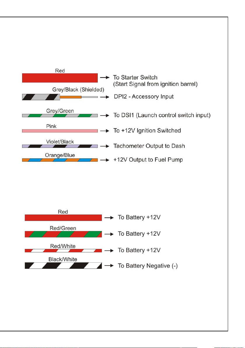
Cabin Wiring
The cabin wiring is made up of multiple inputs and outputs.
Correct connection of these cables is essential for proper operation of the harness.
All wires have been labeled and required cables should be connected as outlined below.
Battery Connections
The following cables will connect directly to the battery on the vehicle
Figure 3 – Harness Cabin and Battery wiring
Page 12

HALTECH HEAD OFFICE: PH: +612 9729 0999
FAX: +612 9729 0900
EMAIL: sales@haltech.com
HALTECH US OFFICE: EMAIL: usa@haltech.com
See the Haltech Website for your local authorized dealer.
www.haltech.com
Version 1
 Loading...