

Page 1
PLATINUM
Sport 1000
Haltech 13B Terminated
Engine Harness
QUICK START GUIDE
Page 2

LIMITED WARRANTY
Lockin Pty Ltd trading as Haltech warrants the HaltechTM Programmable Fuel Injection System to be
free from defects in material or workmanship for a period of 12 months from the date of purchase.
Proof of purchase, in the form of a bill of sale or receipted invoice, which indicates that the product is
within the warranty period, must be presented to obtain warranty service. Lockin Pty Ltd trading as
Haltech suggests that the purchaser retain the dealer’s dated bill of sale as evidence of the date of
retail purchase.
If the HaltechTM Programmable Fuel Injection System is found to be defective as mentioned above, it
will be replaced or repaired if returned prepaid along with proof of purchase. This shall constitute the
sole liability of Lockin Pty Ltd trading as Haltech.
To the extent permitted by law, the foregoing is exclusive and in lieu of all other warranties or
representations, either expressed or implied, including any implied warranty of merchantability or
fitness. In no event shall Lockin Pty Ltd trading as Haltech, be liable for special or consequential
damages.
DISCLAIMER
Haltech will not be held responsible for any damage caused by the incorrect installation or tuning of this
product. It is the installers responsibility to ensure the wiring connections and pinouts match that of the
vehicle the unit is being installed into.
Haltech has taken all care to make sure the connections match the specified vehicles listed, but variations
in wiring and connections on vehicles can occur and therefore this should be checked BEFORE the unit
is installed.
Haltech highly recommends installation and tuning of this product is to be carried out by a professional,
with an understanding on installing and tuning engine management systems.
Misuse of this product can destroy your engine.
WARNING
This ECU is designed and sold for Racing use only. Using this product for street / road use may be
prohibited by law. Please check with your local vehicle authority before using this product.
GENERAL INSTALLATION WARNING
Avoid open sparks, flames or operation of electrical devices near flammable substances.
Always disconnect the battery cables when doing electrical work on your vehicle.
Do not charge the battery with a 24 Volt truck charger or reverse the polarity of the battery
or any charging unit. Do not charge the battery with the engine running as this could
expose the ECU to an unregulated power supply that could destroy the ECU and other
electrical equipment.
All fuel system components and wiring should be mounted away from heat sources,
shielded if necessary and well ventilated. Disconnect the Haltech ECU from the electrical
system whenever doing any arc welding on the vehicle by unplugging the wiring harness
connector from the ECU.
After completing the installation, make sure that there are no fuel leaks, and no wiring
left un-insulated in case a spark or short-circuit occurs and causes a fire. Also make sure
that you follow all proper workshop safety procedures. If you're working underneath
a jacked-up car, always use safety stands!
Page 3

PLATINUM
Sport 1000
Haltech 13B Terminated Engine Harness
Quick Start Guide
Congratulations on purchasing a Haltech Engine Management Terminated Engine
Harness. This Plug and Play product allows you to be up and running in a few hours.
The Harness when installed in conjunction with a Haltech Platinum Sport 1000 opens
the door to virtually limitless performance modification and tuning of your vehicle.
Programmable systems allow you to extract all the performance from your engine by
delivering precisely the required amount of fuel and ignition timing that your engine
requires for maximum output under all operating conditions.
This quick start guide will walk you through installation of the Haltech Terminated Engine
Harness into a vehicle. This guide is accompanied by the full service manual located on
the software CD provided with the ECU that you or your tuner will need to refer to before
completing your installation and configuration. The Manual can also be downloaded from
the Haltech website www.haltech.com
Supported Engine
The Haltech 13B Terminated Engine Harness supports the following engine
configurations:
• Mazda 13B
Supported ECU
• Haltech Platinum Sport 1000
Included in Haltech ECU Kit ( HT051202)
• Haltech Platinum Sport 1000 ECU
• Haltech 13B Terminated Engine Harness
• Haltech Flying Lead Ignition Harness
Optional Accessories ( Sold Separately )
• Haltech LS1 Ignition Harness (Order as ECU Kit # HT051203)
• Haltech LSI Coil (HT020102)
• Haltech Dual Channel Wideband Controller inc 1 Sensor and weld on bung (HT010704)
• Haltech 3 Bar Map Sensor ( HT010104)
• Haltech Air Temperature Sensor -Large thread (HT010202)
Page 4

Harness Overview
The Haltech 13B Terminated Engine Harness is a plug and play solution for wiring
a Mazda Rotary 13B Engine.
Installation is simple and easy as the harness is designed for the engine, all lengths
are correct and all wires are clearly labeled.
The Haltech 13B Terminated Engine Harness comprises of the following:
OEM Connectors
• Injectors x 4
• Crank Angle Sensor
Haltech Sensor Connectors
• MAP Sensor
• Oil Pressure Sensor
• Fuel Pressure Sensor
• Air Temperature Sensor
• Coolant Temperature Sensor
Auxiliary Connections
• Ignition Output
• Main Inputs
• 02 Sensor
• AVI
• Throttle Position Sensor
• Fuel Pump Relay Output
• DPO 3
• In Cabin Inputs and Outputs
Notes on installation:
• Make sure your Engine is grounded.
A Ground / earthing strap should be used to ground your engine to the chassis of the
vehicle. The Haltech Terminated Engine harness does not ground your engine.
Damage can occur to your harness and / or ECU if you do not ground your engine
properly.
• Factory starting and charging circuits are to be used the harness does not incorporate
connections for the starting or charging of the vehicle.
• Keep all wires away from the Exhaust manifold.
Page 5
Harness Connections
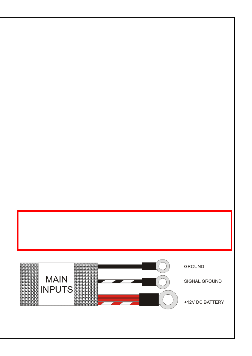
Main Inputs
The main power connections are located within the harness labeled as “Main Inputs”
Injection Battery + (R)
The Injection Battery + (Red) connection will supply the 12V DC to the injector relay
within the harness. Please connect this cable directly to the battery + terminal.
ECU Battery + (R/W)
The ECU Battery + (Red / White) connection will supply the 12V DC to the ECU relay
within the harness. Please connect this cable directly to the battery + terminal.
Battery + (R)
The Battery + (Red) connection will supply the 12V DC to the ignition and
fuel pump relay within the harness. Please connect this cable directly to the
battery + terminal.
Signal Ground (B/W)
The Signal Ground (Black / White) connection supplies the signal ground for the
harness and ECU. Please connect this cable directly to the battery – terminal.
Ground (B)
The Ground (Black) connection supplies the ground for the harness and ECU.
Please connect this cable directly to a chassis ground.
WARNING!
Please make sure your engine block is grounded to the chassis of the vehicle by
a correct sized grounding strap. This harness will not ground your engine,
damage can occur to this harness and / or your ECU if your engine is not
properly grounded.
Figure 1 - Main power Connections
Page 6

In Cabin and DPO 3 Harness
The In Cabin and DPO 3 harnesses comprise of the following wire connections
• Digital Pulsed Outputs 1, 2, 3 & 4 ( V/B, V/BR, V/R, V/O )
When the output is activated by the ECU the output will switch to ground.
Solenoid valves and shift lights etc can be run directly from the output, however high
current devices such as thermo fans and additional fuel pumps must be activated
through a relay. This way the output is only switching the relay and not a high current
draw device.
The Digital Pulsed Outputs are limited to 800mA Max current draw.
These outputs can be programmed within the ECU Manager Software to control
auxiliaries such as:
• Air Con Output
• Aux Fuel Pump
• Boost Control
• ECU Diagnostic Light
• Intercooler Fan
• Shift Light
• Thermo fans
For a full list of output options and explanations please go to the help within the
ECU Manager Software.
• Digital Switched Input 1 ( GY/G )
Digital Switched inputs are inputs that toggle between two states of
low (0V) and high (5V) Voltage to describe the state of a switch or sensor.
These outputs can be programmed within the ECU Manager Software to control
auxiliaries such as:
• Air Conditioning Request
• Auxiliary Rev Limit
• Datalog Activation
• Launch Anti-Lag Switch
• Nitrous Enable
For a full list of input options and explanations please go to the help within the
ECU Manager Software.
Page 7

• Switched 12V DC Supply (GY/R)
This wire supplies an ignition switched 12V DC supply, this can be used to power
the positive side of a relay or solenoid to be controlled by the DPO's
contained within these harnesses.
• Switched +12VDC Input ( P )
This input must be connected to a +12VDC Switched ignition source.
This is required to turn on the Haltech ECU and all the relays contained
within the terminated harness.
Figure 2 - In Cabin Wire Harness
Figure 3 – DPO 3 Wire Harness
Page 8

AVI Harness
The AVI harness connector comprises of the following connections
• Signal Ground (B/W)
This wire supplies a Signal Ground
• AVI 1 & AVI 2 ( GY/Y & O/B)
Analogue Voltage Inputs accept variable voltage inputs from 0V to 5V.
These inputs can also accept switch inputs that change between two different voltage
levels. The on voltage and off voltage define what the thresholds are between the on
and off states. The voltage can be viewed as a channel in the software to determine the
thresholds for a switched input.
• Switched 12V DC Supply (GY/R)
This wire supplies an ignition switched 12V DC supply
Figure 4- AVI Connector Pinout
Fuel Pump Relay Control
The Fuel pump relay control harness comprises of the following wire connections
• Fuel Pump Relay Control (B/Y)
This output controls the fuel pump relay, and should be connected to the coil of the
fuel pump relay. When activated by the ECU the output will switch to ground.
• Switched 12V DC Relay Supply (GY/R)
This wire supplies an ignition switched 12V DC supply, this can be used to power
the positive side of the fuel pump relay. This wire is not to be used to supply power
to the fuel pump.
Figure 5 - Fuel Pump Relay Control Harness
Page 9

02 Sensor Connector
The 02 Sensor connector comprises of the following connections:
Signal Ground (B/W)
This is a signal ground and can be used for grounding a 3 wire 02 Sensor or a
Wideband 02 Controller.
02 Input Signal (GY/O)
Connect the output of a Narrowband 02 Sensor or the output of a Wideband Controller
to this connection.
+5V DC Switched (O)
This is a +5V DC Supply
+12V DC Switched (GY/R)
This is the +12V DC Supply for powering the heater on a 02 Sensor or for powering
the Wideband 02 Controller
Figure 6 - 02 Sensor Connector
Throttle Position Sensor Connections
The Throttle Position Sensor comprises of the following connections:
Signal Ground (B/W)
This wire supplies the Signal Ground to the Throttle Position Sensor
TPS Signal (W)
This wire is the signal to your ECU, Please connect this to the signal output
of your Throttle Position Sensor
+5V DC (O)
This wire supplies the Throttle Position Sensor with an ignition switched +5V DC Supply
Figure 7 – Throttle Position Sensor Connections
Page 10

Manifold Pressure Sensor
The Manifold Pressure Sensor connector plugs directly into any
Haltech 2 and 3 Bar MAP sensors (sold separately)
Figure 8 – Manifold Pressure Sensor Connector
Fuel Pressure and Oil Pressure Sensors
The fuel and oil pressure sensor connectors will plug directly into a
Haltech fuel or oil pressure sensor (sold separately)
The wiring is as follows
A: Signal Ground
B: +5V DC
C: Sensor Output Signal
Figure 9 – Fuel Pressure Sensor Connector
Figure 10 – Oil Pressure Sensor Connector
Page 11

Ignition Output Connector
The Ignition Output Connector comprises of the following connections:
Ignition Outputs (IGN1 – IGN4)
The Platinum Sport 1000 13B Terminated Loom has two options for the ignition
harness, please select option upon ordering of your terminated harness kit:
• Flying Lead Ignition Harness (Kit # HT051202)
• Terminated LS1 Ignition Harness (Kit # HT051203)
The chosen Ignition harness will connect to the 8 position Deutsch connector
labeled as “Ignition Outputs”
The Haltech Platinum Sport 1000 cannot fire the coils directly, and an optional
ignition module will need to be purchased if the LS1 ignition option is not chosen.
Optional Modules (Sold Separately)
Single Channel Ignitor : # HT020000
Dual Channel Ignitor: # HT020002
Triple Channel Ignitor: # HT020004
Quad Channel Ignitor: # HT020006
+12V DC Switched ( P )
This wire supplies a switched +12V DC to the ignition connector this can be used
in CDI applications to enable the CDI unit.
Ground ( B )
This wire supplies a ground to the ignition module or coils
+12V DC From Ignition Relay ( R/Y )
This wire supplies a switched +12V DC to the ignition module or coils from the
ignition relay.
Figure 11 - Ignition output connector
Page 12

Haltech Ignition Harness Overview
The Haltech 13B Terminated Harness has two ignition harnesses available
Please specify at time of purchase.
Haltech LS1 Ignition Harness (Supplied with kit # HT051203)
The Haltech LS1 Ignition harness is designed to be a plug and play solution when
used with Haltech LS1 Coils ( Purchased separately, order as part # HT020102).
With the additional purchase of four LS1 coils this harness will simply plug in.
The use of Haltech LS1 Coils with your engine package will save you time and money,
as these coils have inbuilt ignitors, so ignition modules will not need to be purchased.
Figure 12 – Haltech LS1 Ignition Harness Connections
Haltech Flyloom Ignition Harness (Supplied with kit # HT051202)
The Haltech Flyloom Ignition harness is designed to allow the end user alternative
options for their ignition system. The Haltech Fly loom ignition harness can be wired
to existing ignition modules or used to trigger a CDI system.
Figure 13 – Haltech Flyloom Ignition Harness Connections
Page 13

*Ignition Output Identification
The outputs of the Ignition Harness can be identified by the coloured stripe on
the yellow wires, Please see figure 14 below:
Figure 14 – Haltech Ignition Looms Output Colour Guide
Page 14

Appendix
Series 6 Engine Harness Conversion
Crank Angle Sensor
To Convert the Haltech Terminated harness to be used with a Series 6 engines
the Crank angle sensor connection must split into two sensor connectors.
Cut your existing connectors off your original harness and solder them to the
Haltech terminated harness as shown below
Figure 15 – Series 6 Crank Angle Sensor Wiring
Page 15

Throttle Position Sensor Connections
Connections to the Throttle Position Sensor for both series of engines are outlined
below .
Figure 16 – Series 5 Throttle Position Sensor Wiring
Figure 17 – Series 6 Throttle Position Sensor Wiring
Page 16

Oil Metering Pump Connection
The Haltech 13B Terminated Harness does not support the electronic
oil metering pump.
This feature can be added by the addition of 7 wires.
Please follow the wiring diagrams below.
Figure 18 - Wiring in a Series 5 electronic Oil Metering Pump
Page 17

Figure 19 - Wiring in a Series 6 electronic Oil Metering Pump
Page 18

Appendix
Upon installation fill out the table below, this will help when it comes to setup
and tuning of the vehicle
Input / Output
Analogue Voltage
Inputs
AVI 1 (GY/Y) AVI
AVI 2 (O/B) AVI
Digital Switched
Inputs
DSI 1 (GY/G) In Cabin
Digital Pulsed
Outputs
DPO1 (V/B) In Cabin
DPO2 (V/BR) In Cabin
DPO3 (V/R) DPO 3
DPO4 (V/O) In Cabin
Figure 20 - User Definable Inputs and Outputs Allocation Table
Wire
Colour
Harness
Location
Configuration
Page 19

Notes
Page 20

HALTECH HEAD OFFICE: PH: +612 9729 0999
FAX: +612 9729 0900
EMAIL: sales@haltech.com
HALTECH US OFFICE: EMAIL: usa@haltech.com
See the Haltech Website for your local authorized dealer.
www.haltech.com
Version 2 Harness Revision 2
 Loading...