

Page 1

Page 1 of 19
HAL-HCO201
Handheld Carbon Dioxide
Meter/Monitor
Operational Manual
625 E Carroll Avenue
Glendora, CA 91741 USA
Phone: (510) 579-8540
Fax: (626) 236-9246
Info@haltechnologies.com
http://haltechnologies.com
Page 2

Page 2 of 19
This Page intentionally left as blank
Page 3

Page 3 of 19
Table of Contents
Important Messages.........................................................................4
I. Introduction..................................................................................6
1.1 Features................................................................................7
1.2 Specifications........................................................................ 7
II. Basic Operation..........................................................................9
2.1 Measuring Screen.................................................................9
2.2 Browsing Screen................................................................. 11
2.3 Setting Screen..................................................................... 13
2.4 Calibration........................................................................... 13
III. Warrantee.................................................................................16
Contact......................................................................................18
User Registration Form................................................................19
Page 4

Page 4 of 19
Important Messages
The information in this manual is believed to be accurate to date. However, Hal
Technology assumes no responsibility for any inaccuracies that may be contained in this
manual. In no event will Hal Technology be liable for direct, indirect, special, incidental,
or consequential damages resulting from any defect or omission in this manual, even if
advised of the possibility of such damages. In the interest of continued product
development, Hal Technology reserves the right to make improvements or changes in
this manual and the products it describes at any time, without notice or obligation.
Published in the United States of America
Copyright © 2008 by Hal Technology
All rights reserved. No part of the contents of this manual may be reproduced,
transmitted, stored, or translated into any other language in any form by any means
without the written permission of Hal Technology.
Quality Assurance
• This product has met the product specifications. All the test instruments and
standard materials used for calibration are traceable.
• This certification is for new production only and not valid for used one or ones
for an exhibition purpose.
Commonly used symbols in this manual
Following symbols are used throughout this manual:
The action could lead to harmful damage to the instrument.
Bring you attention about the features of the instrument.
Unpacking and Inspection
• Inspect the receiving package and notify the shipper immediately if there
appears to be susceptible damage during shipping.
Page 5

Page 5 of 19
• Please verify that the enclosed items match with the shipping package list.
This Instrument also contains static sensitive components that may be damaged by
improper handling. The warranty is void for any unauthorized opening of the
instrument.
Environmental Requirements
To avoid any accident or damage to the instrument, please avoid using in the
following situations:
• DO NOT expose to combustible, explosive environments.
• DO NOT expose to environments where rust or radioactivity are present.
• DO NOT expose to an environment exceeding the specified limits.
Technical Support and Warrantee
Within a year from the date purchased, the manufacturer will provide free technical
support and software upgrade if applicable. For additional help, please contact
info@haltechnologies.com
It is strongly recommended that the instrument should be calibrated
semi-annually or annually at most. Please contact Hal Technology to schedule
your calibration or any services needed. The HAL-HCO201 can only be serviced
at Hal Technology or by Hal Technology’s authorizing trained professionals.
Page 6

Page 6 of 19
I. Introduction
Carbon monoxide (CO
2
) is one of the most common gases existing in daily life and
industry. Carbon Dioxide, colorless and odorless, is a natural component of air at
approximately 0.03 %. The HAL-HCO201 handheld carbon dioxide meter is a
compact personal monitor that can provide a rapid indication of CO
2
levels at the touch
of a button. The HAL-CO201, based on the most reliable and accurate dual-beam,
non-dispersive infrared (NDIR) sensing technology, features directly displays the
carbon dioxide concentration in ppm or percentage.
Low-power consumption design enables long operation time. Exceptional stability
and patented self-calibration algorithm allow very long intervals between calibration
intervals. The external digital temperature and humidity sensor or pressure sensor,
when applicable, allows compensation or correction for accurate measurement. The
USB port provides capability of downloading stored data and possible continuous,
real-time monitoring of the environment. The HalTech HCO201 Carbon Dioxide
meter makes it easy to take quick measurements of a wide range of CO
2
levels. With
a built-in pump, the HCO201 is a point-to sample instrument and responds very quickly
to ambient changes in CO
2
concentration.
The HAL-HCO201 Carbon Dioxide monitor can be widely used for continuous
Page 7

Page 7 of 19
environment monitoring system (CEMS), environment protection, hygiene and
epidemic prevention system, as well as air pollution and greenhouse testing.
1.1 Features
• Easy to use - minimal operator training required
• Wide measuring range
• Rapid response time
• Direct real time readings allow immediate response to results
• Reliable electrochemical sensor
• Large data storage capability
• Auto back light (power saving)
• High-speed USB connectivity
• Simple and easy in-field calibration
• External digital temperature and humility sensors to assure accurate
measurement
• Audible excess limit warning (user defined)
• No less than 3 hours of continuous operation.
1.2 Specifications
• Target Gas: Carbon Dioxide (CO2) in air
• Sensor Technology: Non-dispersive Infrared (NDIR) optical sensor
• Sampling Method: Pump and pointing sampling
• Range: 0 ~ 5000ppm
• Warm up Time: < 2 minutes
• Response Time: < 5 seconds
• Accuracy: ±40ppm+3% of reading @22°C
• Stability: <2% full scale over the life of sensor (15 years typical)
• Non-linearity: < ± 1% of full scale
• Temperature Dependence: 0.2% full scale per degree C (°C)
• Pressure Dependence: 0.13% of reading per mmHg (if no correction)
• Expected Sensor Life: 15 years typical in non-corrosive environment.
Page 8

Page 8 of 19
• Calibration Interval: Typical not required
• Display Unit: ppm (4 digit LCD)
• Memory: Up to 500 sets of data
• Interface: USB
• Power: Rechargeable Lithium ion battery (3.7V/900mAh); AC adapter 100~
240VAC to 5VDC/1A
• Dimension: 80 (W) × 150 (H) × 36 (D) mm
• Weight About 200 grams
• Environmental Condition: Operating: 0~ 50°C, <90%RH non-condensing;
Storage: -20 ~ 70°C, <90%RH
• Standard accessories: AC adapter, USB cable, CD with data download software
and user manual
• Optional accessories: Temperature and humidity sensor probe
Page 9

Page 9 of 19
II. Basic Operation
Six control keypads are used to operate the instrument: , RUN/STOP, ENTER,
BACK, , .
• Power button : Push and hold it for about 2 seconds to turn on the instrument.
After turned on, keep pushing on for about 2 seconds to turn off the instrument.
The instrument will shut off automatically to save the power after about 8
minutes standby or no operation,
• RUN/STOP: Start or stop a measuring/sampling operation.
• : Move the cursor to select desired window page or item.
• ENTER: Confirm the current selection or enter parameter or save current
sampling value.
• BACK: Change the concentration unit in ppm or percentage or back out of the
selection
The bottom of the enclosure includes
• USB Interface: Connect to the USB interface to a computer for data downloading,
remote sampling or firmware upgrading. Contact the manufacturer or sale
representatives for availability of these functions.
• POWER port: An AC adapter plug-in port.
• Charge Status LED: LED flashes during charge and becomes steady after the
charge finished.
2.1 Measuring Screen
The Measuring Screen is the main screen of the instrument for sampling testing. This
screen can be run at the default settings. It displays the test result and conditions
according to the unit settings. One may wish to change the settings before a
measurement run by pressing up or down arrow to enter into the Setup Screen. An
example of the Measuring Screen is shown in the Figure 1.
Page 10

Page 10 of 19
Figure 1 Measuring Screen
Battery Indicator
The battery indicator displays the battery strength graphically. Four bars represent
100% of charge in the battery; three bars 75%; two bars 50%; one bar 25%. No bars
signify a low battery status and simultaneously the alarm will buzz as a warning.
Charging of the battery is necessary at this level and after a few seconds of the warning
sound the instrument shuts itself off automatically.
Time and Date
The current date and time is always displayed in the format of year-month-day and hour:
minute: second, respectively. Date and time can be changed in the Setting screen.
Temperature & Relative Humidity (T and R/H)
Temperature and Relative Humidity automatically displays when an external
temperature and humidity sensor probe is attached.
• Use BACK keypad to toggle the concentration unit between ppm and
percentage if the sampling is not started.
• Push RUN/STOP keypad to start continuous measuring/sampling. During
the sampling process, the backlight will be off automatically.
• Data are logged or current sampling value will be saved every time when
the ENTER keypad is pressed. Push RUN/STOP keypad to stop measuring
and the backlight will be on again.
Measuring
CO
2
: 658 ppm
2007-09-06 08:47:25
23°C 68%RH ---- mbar
Page 11

Page 11 of 19
• The instrument will automatically turn off the power in 8 minutes or so if no
keypad action was received. However, the power will not be automatically
turned off as long as a sampling (with a running pump) is in process.
Pressure
When it is applicable, the current pressure value will be displayed in Pa when an
external pressure sensor is attached. The calibration data is set in the Setting screen.
• Auto backlight is on and the instrument will automatically turn off the
backlight after about several seconds if there is no keypad action.
• The instrument will be automatically turned off if there is no keypad action
after about eight minutes.
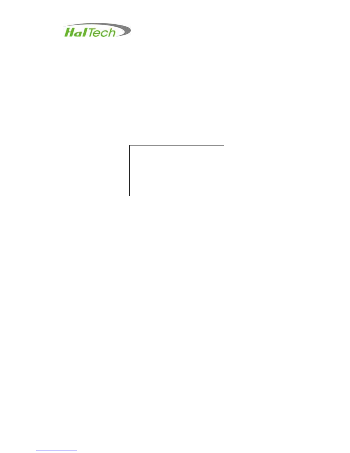
2.2 Browsing Screen
Press the arrow keypad to select the Browsing screen and enter into this page (Figure
2). This screen will allow the user to browse or delete historic data.
Figure 2 Browsing Screen
In the Browsing screen, press ENTER keypad to enter into the last saved data record
(Figure 3). Then use the arrow keypad to scroll through the stored data.
• Use keypad to go to the next saved data record.
• Use keypad to return to the previous saved data record.
Browsing
ppm
Te mp : °C RH: %
Page 12

Page 12 of 19
• Use BACK keypad to return to the main Browsing window. BACK keypad is
effective only after entering into the data record.
Figure 3 An example of the Browsing Screen
Record
Record format as current number of saved data/total number of stored data. (e.g.,
028/028). In the Figure 3, one views the last data in the record with the total 20 of data
sets stored.
Delete the record
• Press an arrow keypad to move up or down to select the record to be deleted.
• Use the arrow keypad to select Delete one or Delete all. Then press ENTER
keypad to delete the current record (in this case, the total number of record will
be reduced one while the next record number will be moved to replace the
delete one), or delete all the records.
Figure 4 An example of deleting records in the Browsing Screen
Browsing
028/028
506 ppm
2008-08-06 08:42:25
Te mp :2 4°C RH:56%
Browsing
004/050
509 ppm
2008 7:41
TEMP: 66%
Delete
one/all
Page 13
Page 13 of 19
2.3 Setting Screen
The Setting screen allows users to set or change Date, Time, and warning limit. Use an
arrow and ENTER keypads to enter into the Setting screen. Then press the ENTER
keypad to highlight the parameter that needs to be changed / set. The chosen
parameter will be at the bottom of the window. Press ENTER keypad again and using
the keypads scroll through the parameter options or change the number and then press
ENTER to confirm the parameter’s setting. Press BACK keypad to back to the previous
screen.
Figure 5 Setting Screen
Alarm level setting
The user may turn on or off the excess exposure limit warning. The user may input any
value at the increment of 1ppm between 0 and 5000ppm. For your reference, two
levels of limit for carbon monoxide are in common: 1) Threshold Limit Value (TLV) of
5,000 ppm (9,000 mg/m
3
) as a "ceiling limit" established by The National Institute for
Occupational Safety and Health (NIOSH) or American Conference of Governmental
Industrial Hygienists (ACGIH); 2) Permissible Exposure Limit (PEL) of 5,000 ppm
established by US Occupational Safety & Health Administration (OSHA). All of these
concentrations refer to exposures with durations of 8 hr/day, 40 hr/week for a working
lifetime and all are attempts to establish a "no effect" level. The Immediately Dangerous
to Life and Health (IDLH) limit is 40000ppm.
2.4 Calibration
After turning on the instrument, use up or down keypad to go to the Calibration Screen
(Figure 6). Users may calibrate the instrument at his/her own wish after using for a
certain time of period or suspect degradation of sensor performance.
Setting
Date………[2008-09-06]
Time………[ 08:47:25 ]
Alarm………[ OFF ]
Page 14
Page 14 of 19
Figure 6 Calibration Screen - 1
Recommended calibration method is the standard Zero-Span technique. The X
values in the first column represent the concentration of calibrating gas in ppm. The Y
values in the second column represent the response of the sensor to be calibrated. The
values in the third column are calibration coefficients. The default values of K and B are
1.00 and 0, respectively. Factory calibration was performed under the condition of
altitude at the sea level. One can set the altitude from 0 to 5000 feet to correct
variation of CO
2
concentration due to the altitude change. The example of calibration
procedures is described below:
Here we use a zero air and the vapor concentrations of 1000 ppm of carbon dioxide
standard gas cylinder as an example for calibration:
1) Enter into the calibration screen by pressing the ENTER keypad
2) Use up or down keypad to move the cursor to Altitude value if change is needed.
Set the altitude value at the proper height in feet. Press ENTER to confirm the
change.
3) Connect the inlet of the instrument to a glass container and then introduce the zero
air to the glass container
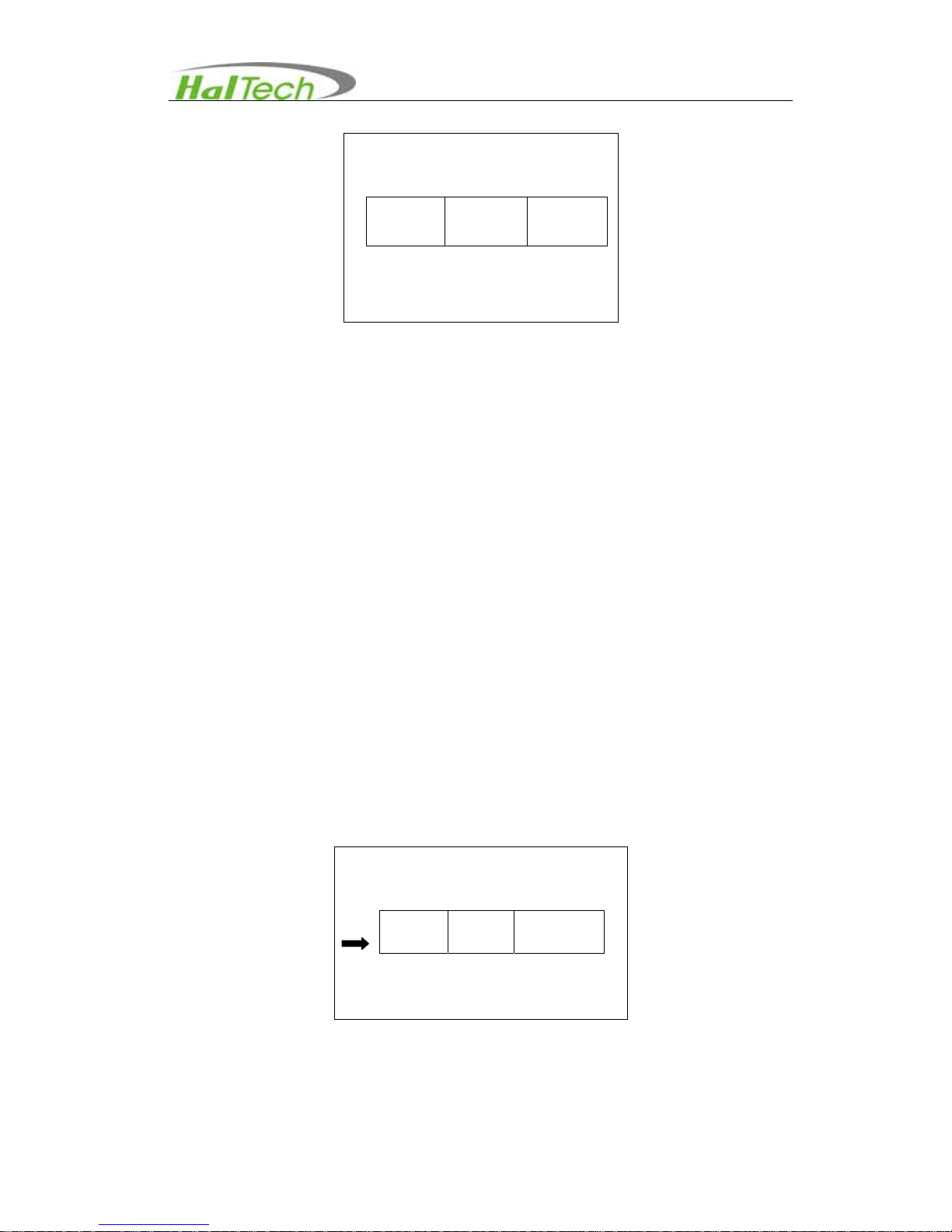
4) Enter into the calibration screen by pressing the ENTER keypad and make sure
that the left arrow pointed at the first row of 0ppm concentration (refer to Figure 7).
Figure 7 Calibration Screen -2
Calibration
[X] [Y] [K B]
0000
1000
0000
0610
+ 1000
+ 0000
Reset
Altitude: 0535 feet
Calibration
[X] [Y] [K B]
0000
1000
0000
0610
+ 1000
+ 0000
Reset
Altitude: 0535 Feet
Page 15

Page 15 of 19
5) Press RUN/STOP keypad to start a sampling. Wait for right bottom number stable
and then press STOP key.
6) Connect the inlet to a glass container that is connected a standard CO
2
gas cylinder
(e.g., 1000ppm standard carbon dioxide gas cylinder).
7) Move the cursor to the second row (Refer to Figure 8) and then press the ENTER
keypad. Use or to select the element to be changed. When the
element of the X column becomes highlighted, use or to change the
number and press ENTER to confirm the change. Set the number as the
concentration level of the standard gas concentration to be tested (e.g., 1000ppm).
Then use BACK keypad to return to non-change screen with the cursor pointing at
the second row.
Figure 8 Calibration screen- 3
8) Press RUN/STOP keypad to sample, the correspondence value in the Y column will
display the response of the concentration for current liquid standard. Press
RUN/STOP keypad again to stop the sampling after the reading is stabilized.
9) After finished both samplings on standard gases, move the cursor back to the first
row, press and hold the ENTER key for about two seconds. The instruments will
automatically calculate and update the calibration coefficients based on new
calibrations. Press ENTER to save values.
10) After finishing calibration procedures, press BACK to exit.
• To restore the default settings of factory calibration, move cursor to highlight
RESET and then press ENTER to restore factory calibration for coefficients of K
and B. press BACK key to exit.
• One can always bypass the zero-air calibration if it is not necessary. In order
to do so, move the cursor back to the first row after taking the non-zero gas
calibration, press and hold the ENTER key for about two seconds. The
instruments will automatically calculate and update the calibration coefficients
based on new non-zero gas calibration (SPAN calibration) only. Press ENTER
to save values.
Calibration
[X] [Y] [K B]
0000
1000
0000
0856
+ 1000
+ 0027
Reset
Altitude: 0535 Feet
Page 16

Page 16 of 19
III. Warrantee
Hal Technology provides a one-year limited warranty of the Model HCO201 Handheld
Carbon Monoxide meter, but not including necessary calibration service.
• Warranty begins from shipping date.
• The user is responsible for the cost of shipping in the case of any service or
repair needed.
• The warrantee only limits to the HCO201 and HAL TECHNOLOGY does not
extend this liability to accessories and any other equipment damage, body injury
and loss of properties due to abnormal use.
The following are not included in the warranty:
• Improper connection to a power source, resulting in damage of the instrument.
• Any physical damage due to mechanical forces (e.g., collision or dropping) that
may cause any damage of the front panel, LCD screen, switch and internal
components, etc.
• Unauthorized opening of the instrument.
• Damage due to operation in an un-specified environmental condition.
• Abnormal operation due to instrument needing calibration.
Limitation of Warranty
A. Hal Technology warrants that all equipment shall be free from defects in material and
workmanship under normal use for a period of one year from date of shipment to Buyer
except that Hal Technology does not warrant that operation of the software will be
completely uninterrupted or error free or that all program errors will be corrected. Buyer
shall be responsible for determining that the equipment is suitable for Buyer’s use and
that such use complies with any applicable local, state, or federal law. Provided that
Buyer notifies Hal Technology in writing of any claimed defect in the equipment
immediately upon discovery and any such equipment is returned to the original
shipping point, transportation charges prepaid, within one year from date of shipment to
Buyer and upon examination Hal Technology determines to its satisfaction that such
equipment is defective in material or workmanship, i.e. contains a defect arising out of
the manufacture of the equipment and not a defect caused by other circumstances,
Page 17

Page 17 of 19
including, but not limited to accident, misuse, unforeseeable use, neglect, alteration,
improper installation, improper adjustment, improper repair, or improper testing, Hal
Technology shall, at its option, repair or replace the equipment, shipment to Buyer
prepaid. Hal Technology shall have reasonable time to make such repairs or to replace
such equipment. Any repair or replacement of equipment shall not extend the period of
warranty. If the Instrument is modified or in any way altered without the explicit written
consent of Hal Technology then the warranty is null and void. This warranty is limited to
a period of one year, except as noted below, without regard to whether any claimed
defects were discoverable or latent on the date of shipment.
B. If Buyer shall fail to pay when due any portion of the purchase price or any other
payment required from Buyer to Hal Technology under this contract or otherwise, all
warranties and remedies granted under this Section may, at Hal Technology’s option,
be terminated.
C. Warranty repairs shall be completed at a Hal Technology authorized service location,
by an authorized service technician, or on site at buyer’s facility by a Hal Technology
authorized employee. Buyer pays shipping costs to factory; seller will pay standard
return shipping costs during the warranty period. A buyer may select a faster method of
shipment at his/her own expense.
Warranty of Repairs after Initial One (1) Year Warranty
A. Upon expiration of the initial one-year warranty, all parts and repairs completed by an
authorized Hal Technology repair technician are subject to a six (6) month warranty.
B. Other than the above, Hal Technology makes no warranty of any kind, expressed or
implied, except that the products manufactured and sold by Hal Technology shall be
free from defects in materials and workmanship and shall conform to Hal Technology’s
specifications; Buyer assumes all risk and liability resulting from use of the products
whether used singly or in combination with other products. If instrument is modified or in
any way altered without the explicit written consent of Hal Technology, then the
warranty is null and void.
C. Warranty repairs shall be completed at a Hal Technology authorized service location,
by an authorized service technician, or on site at buyer’s facility by a Hal Technology
authorized employee. Buyer pays shipping costs to factory; seller will pay standard
Page 18

Page 18 of 19
return shipping costs during the warranty period. Buyers may select a faster method of
shipment at their own expense.
Contact
HAL TECHNOLOGY, LLC
625 E Carroll Avenue
Glendora, CA 91741 USA
Phone: (510) 579-8540
Fax: (626) 963-7302
Info@haltechnologies.com
http://haltechnologies.com
Information Record
Model __
Serial No. __
Purchase Place
Address
_
Phone
Service Place
Address
_
Phone
Preferred Contact Method
□ E-mail □ Mail □ Phone
Page 19

Page 19 of 19
Please fill out the Registration form below and send to:
HAL TECHNOLOGY, LLC
625 E Carroll Avenue
Glendora, CA 91741 USA
Phone: (510) 579-8540
Or send relevant registration information to the email address below:
services@haltechnologies.com
User Registration Form
Company _____
Contact Person ______________
Address ______
______ __
City ____
State/Province Country _____
Postal Code _________
Phone ________________
Fax __________________
E-mail _____________________
Product Model ______
Serial No. ______________________________
Purchase Date
Purchase Place _
Preferred Contact Method
□ E-mail □ Mail □ Phone
 Loading...