

Page 1

F10X Manual
Warning
1. The F10X ECU must only be used with an F10X wiring
harness. Note that the wiring harness of the F10 will physically
plug into the F10X ECU (and vice-versa), however, the pin
connections are different and this will lead to improper operation
of the ECU and possible damage to it. The F10X wiring harness
is clearly labelled as “X” near the main ECU connector.
i
Page 2

F10X Manual
Contents
INTRODUCTION....................................................................................................................7
SECTION 1 GETTING STARTED ............................................................................... 11
CHAPTER 1 Haltech ECU Installation ............................................................................... 11
1.1 The ECU and Associated Hardware........................................................................... 11
1.2 Installation Summary .................................................................................................11
1.3 Expanded Installation Guide ...................................................................................... 12
1.3.1 Manifold Absolute Pressure (MAP) Sensor........................................................ 12
1.3.2 Coolant Temperature Sensor............................................................................... 13
1.3.3 Inlet Air Temperature Sensor.............................................................................. 14
1.3.4 The Throttle Position Sensor (TPS) .................................................................... 15
1.3.5 Mount Optional Exhaust Gas Oxygen Sensor..................................................... 16
1.3.6 Route Wiring Harness and Connect Sensors....................................................... 16
1.3.7 Power Relays....................................................................................................... 16
1.3.8 Fuse Block Assembly.......................................................................................... 17
1.3.9 Electronic Control Unit (ECU) ........................................................................... 18
1.3.10 Flying Leads...................................................................................................... 18
1.3.11 Install and Connect Optional Idle Speed Motor................................................ 19
1.3.12 Install and Connect any Optional Outputs ........................................................ 19
1.3.13 Connect the Trigger Sensor............................................................................... 20
1.3.14 Connect the ECU............................................................................................... 20
CHAPTER 2 Installing The Software.................................................................................. 21
2.1 Computer Requirements............................................................................................. 21
2.2 Operating the Software............................................................................................... 21
2.2.1 Installing the Software ........................................................................................ 21
2.2.2 Running the Software.......................................................................................... 23
CHAPTER 3 Operating the Software .................................................................................. 24
3.1 The Menu Structure.................................................................................................... 24
3.1.1 The File Menu ..................................................................................................... 24
3.1.1.1 Load From File............................................................................................. 25
3.1.1.2 Save To File ................................................................................................. 25
3.1.1.3 Load E6K/F10/E6GM Fuel Maps ................................................................ 26
3.1.1.4 Quit............................................................................................................... 26
3.1.2 The Map Menu .................................................................................................... 27
3.1.2.1 Fuel Maps..................................................................................................... 27
3.1.2.2 Fuel Correction Maps................................................................................... 29
The Set-up Menu.......................................................................................................... 29
3.1.3 The Options Menu............................................................................................... 29
3.1.4 Data Page Menu .................................................................................................. 30
3.1.5 Password Protection ............................................................................................ 30
3.2 Online and Offline Operation..................................................................................... 31
3.2.1 Going Online....................................................................................................... 31
3.2.2 The Engine Data and Gauge Page....................................................................... 32
3.3 Hot Key Summary...................................................................................................... 33
CHAPTER 4 Configuring the ECU ..................................................................................... 34
4.1 Using the ECU Set-up Pages...................................................................................... 34
4.2 The ECU Set-up Pages............................................................................................... 34
ii
Page 3

F10X Manual
4.2.1 Main Set-up Page ................................................................................................ 34
4.2.2 Fuel Set-up Page.................................................................................................. 36
4.2.3 Trigger Setup....................................................................................................... 39
4.2.4 The In/Out Set-up Page ....................................................................................... 39
CHAPTER 5 Haltech Maps ................................................................................................. 43
5.1 What are Maps?.......................................................................................................... 43
5.2 What is Mapping the Engine? .................................................................................... 44
5.2.1 Adjusting Bar Height In a 2D Map ..................................................................... 44
5.2.2 All Ranges........................................................................................................... 45
5.2.3 Percentage Changes............................................................................................. 45
5.2.4 Linearise.............................................................................................................. 46
5.2.5 Numeric Mode..................................................................................................... 47
5.2.6 3D View ..............................................................................................................48
5.3 The Haltech Maps ...................................................................................................... 49
5.3.1 Fuel Map – 3-Dimensional.................................................................................. 49
5.3.2 Fuel Correction Map ...........................................................................................49
5.3.2.1 Coolant Temperature Correction.................................................................. 49
5.3.2.2 Air Temperature Correction......................................................................... 49
5.3.2.3 Battery Voltage Correction .......................................................................... 49
5.3.2.4 Fuel Priming Map......................................................................................... 50
5.3.2.5 Post Start Map .............................................................................................. 50
5.3.2.6 Barometric Pressure Map ............................................................................. 50
5.3.2.7 Gas Pressure Map......................................................................................... 50
5.3.2.8 Gas Temperature Map.................................................................................. 50
5.3.3 Zero Throttle Map ............................................................................................... 51
5.3.4 Full Throttle Map ................................................................................................ 51
5.3.5 Turbo Waste-gate Maps ...................................................................................... 51
5.3.6 Torque Converter Control Map........................................................................... 51
5.4 Dual Maps .................................................................................................................. 52
5.4.1 Editing Dual Maps .............................................................................................. 52
SECTION2 TUNING THE ENGINE............................................................................ 53
CHAPTER 6 Starting the Engine......................................................................................... 53
6.1 Calibrating the Throttle Position Sensor .................................................................... 53
6.2 Checking the Trigger.................................................................................................. 53
6.3 Determining Engine Fuel Needs ................................................................................ 53
6.3.1 Starting using the Manifold Pressure Load Sensing ........................................... 54
6.3.2 Starting using the Throttle Position Load Sensing.............................................. 54
6.3.3 Useful Software Mapping features...................................................................... 54
6.3.4 Tuning for Idle .................................................................................................... 55
6.3.5 Tuning with No Load .......................................................................................... 55
6.3.6 Loading the Engine ............................................................................................. 56
6.3.6.1 On the Dyno ................................................................................................. 56
6.3.6.2 On the Road.................................................................................................. 56
6.3.7 Fine Tuning the Engine ....................................................................................... 56
CHAPTER 7 Throttle Effects .............................................................................................. 58
7.1 Throttle Response....................................................................................................... 58
7.2 Zero Throttle Map ...................................................................................................... 59
7.3 Full Throttle Map ....................................................................................................... 59
CHAPTER 8 Cold Starting and Running............................................................................. 60
iii
Page 4

F10X Manual
8.1 Cold Cranking ............................................................................................................ 60
8.2 Fuel Correction Versus Coolant Temperature ........................................................... 60
CHAPTER 9 Correction Factors.......................................................................................... 61
9.1 Fuel Versus Air Temp Map........................................................................................ 61
9.2 The Battery Voltage Map........................................................................................... 61
9.3 Barometric Correction................................................................................................ 62
9.3.1 Barometric Correction - Method 1 ...................................................................... 63
9.3.2 Barometric Correction - Method 2 ...................................................................... 63
9.3.3 Barometric Correction - Method 3 ...................................................................... 64
9.4 Post Start Enrichment................................................................................................. 65
SECTION 3 SOFTWARE FEATURES......................................................................... 66
CHAPTER 10 Data logging................................................................................................. 66
10.1 The Data log Option................................................................................................. 66
10.1.1 Creating a Data log............................................................................................ 66
10.1.2 Selecting the Data Channels.............................................................................. 67
10.1.3 Logging the Data............................................................................................... 67
10.1.4 Displaying The Data.......................................................................................... 68
10.1.4.1 Displaying Channels .................................................................................. 69
10.1.4.2 Changing scales on a View ........................................................................ 70
10.1.4.3 Viewing Multiple Datasets......................................................................... 70
10.1.4.4 Removing A Dataset .................................................................................. 70
10.1.4.5 Data Values ................................................................................................ 71
10.1.4.6 Zooming ..................................................................................................... 71
10.1.4.7 Changing the Trace Width ......................................................................... 72
SECTION4 INPUTS & OUTPUTS ............................................................................... 73
CHAPTER 11 Output Options Set-Up................................................................................. 74
11.1 Idle Speed Control and O
Closed Loop Control..................................................... 74
2
11.1.1 Idle Control ....................................................................................................... 74
11.1.2 O2 Closed Loop Fuel Control ........................................................................... 76
11.2 The PWM Options Page........................................................................................... 78
CHAPTER 12 Digital Outputs & PWM Outputs................................................................. 79
12.1 Turbo Waste Gate Control (TWG)........................................................................... 79
12.2 Bypass Air Control (BAC) Valve ............................................................................80
12.3 Dual Intake Valve Control (DIV)............................................................................. 80
12.4 Torque Converter Clutch Lockup (TCC)................................................................ 81
12.5 Electric Thermo Fan Control (TF) .......................................................................... 81
12.6 Electric Intercooler Fan Control (IF) ...................................................................... 81
12.7 Shift Light Illumination (SL) .................................................................................. 82
12.8 Auxiliary Fuel Pump (AP) ...................................................................................... 82
12.9 Anti-Stall Solenoid Control (AS)............................................................................. 82
12.10 Staging Signal Function (SS) ................................................................................ 83
12.11 Turbo Timer (TT)................................................................................................... 83
12.12 NOS Switch ............................................................................................................ 83
12.13 Air Conditioning .................................................................................................... 84
12.14 Engine Control Relay............................................................................................. 84
12.15 VTECH................................................................................................................... 85
12.16 BAC2...................................................................................................................... 85
12.17 BAC/BAC2 Slave (Bipolar idle valves)................................................................. 86
iv
Page 5

F10X Manual
12.18 TPS Switch............................................................................................................. 86
SECTION 5 APPENDICES ............................................................................................ 88
Appendix A Troubleshooting ........................................................................................... 88
Appendix B Injection outputs.......................................................................................... 93
Appendix C Injectors........................................................................................................ 97
Appendix D Fuel Systems & Staging ............................................................................... 98
Appendix E Trigger Interface......................................................................................... 103
Appendix G Haltech F10X Specifications...................................................................... 115
Appendix H Wiring Diagrams ........................................................................................ 120
Under copyright law, neither this manual nor its
accompanying software may be copied, translated or
reduced to electronic form, except as specified
herein, without prior written consent of Lockin Pty
Ltd trading as Haltech.
Copyright 2005 Lockin P/L
A.B.N 68 061 744 303
Also trading as HALTECH
10 Bay Road
Taren Point, NSW 2229
Australia
Ph: (+61) (02) 9525 2400
Fax: (+61) (02) 9525 2991
Sales-au@haltech.com
www.haltech.com
MS_DOS is a registered trademark of Microsoft
Corporation. IBM is a registered trademark of
International Business Machines Corporation
v
Page 6

F10X Manual
Print Version: 3.02a.......................................................................................Date: 10 Aug 2005
This manual should accompany:
IBM compatible PC software .................................................................... HalwinX V1.0
Firmware Series ............................................................................................................. 11
Firmware........................................................................................................................ 11
vi
Page 7

F10X Manual
Introduction
Congratulations on your decision to choose a Haltech Engine Management System. Haltech
EFI systems have been successfully installed on thousands of vehicles, from power offshore
boats to twin-turbo Ferraris to jet skis and snowmobiles. Over the past decade, many motorsport enthusiasts have discovered that the Haltech computer is easy to use and performs well
by enabling users to precisely control ignition timing and fuel delivery. Precise ignition and
mixture control leads to excellent drivability and fuel economy, something that is often
lacking in high-performance carburettor engines.
Haltech users have discovered that the flexibility of the Haltech Electronic Control Unit
(ECU) and PC based programming software leads to the easiest possible installation on
everything from traditional pushrod V8s to high performance turbocharged racing
motorcycles. We are proud of the fact that some of the most respected professional racers and
super-car builders in the world use Haltech equipment for the same reasons that Haltech is
popular with motor-sports enthusiasts: it is flexible and friendly; is installed easily; and you
can tune your Haltech simply, without having to make the project a major research effort.
Before You Begin...
1) IT IS BEST TO READ THIS ENTIRE MANUAL BEFORE STARTING.
The greater your knowledge of the operation of the Haltech system, the easier you will find it
to understand what you are doing, and why. Throughout the manual are Warnings and Notes
that will help your installation run smoothly and indicate the dangers that can exist for you the
installer and the Haltech ECU.
2) Read any additional material accompanying this manual that updates the document since it
was written.
3) You may need special parts, additional tools or test equipment in order to complete the
installation. Make sure you have these items on hand before you begin to avoid frustration.
Contact your Haltech dealer if you have difficulty.
4) Don't do the minimum work possible. Carelessness in the early stages of installation can
cause you major headaches later on, be it in a few days or a few months time. Carelessness
will cost you money and frustration in finding and fixing unnecessary problems. You have the
opportunity to make sure your Haltech system's operation is extremely dependable and easy
to use by doing it right the first time.
WARNING:
AVOID OPEN SPARKS, FLAMES, OR OPERATION OF
ELECTRICAL DEVICES NEAR FLAMMABLE SUBSTANCES.
ALWAYS DISCONNECT THE BATTERY CABLES WHEN DOING
ELECTRICAL WORK ON YOUR VEHICLE.
7
Page 8

F10X Manual
DO NOT CHARGE THE BATTERY WITH A 24VOLT TRUCK
CHARGER OR REVERSE THE POLARITY OF THE BATTERY OR
ANY CHARGING UNIT
DO NOT CHANGE THE BATTERY WITH THE ENGINE RUNNING
AS THIS COULD EXPOSE THE ECU TO AN UNREGULATED
POWER SUPPLY THAT COULD DESTROY THE ECU AND OTHER
ELECTRICAL EQUIPMENT.
ALL FUEL SYSTEM COMPONENTS AND WIRING SHOULD BE
MOUNTED AWAY FROM HEAT SOURCES, SHIELDED IF
NECESSARY AND WELL VENTED.
MAKE SURE THERE ARE NO LEAKS IN THE FUEL SYSTEM AND
THAT ALL CONNECTIONS ARE SECURE.
DISCONNECT THE HALTECH ECU FROM THE ELECTRICAL
SYSTEM WHENEVER DOING ANY ARC WELDING ON THE
VEHICLE BY UNPLUGGING THE WIRING HARNESS CONNECTOR
FROM THE ECU.
5) Electromagnetic interference (EMI) from unsuppressed spark plugs and leads can cause the
ECU to fail. Please do not use them.
6) In hot climates, or with turbocharged engines, you may need to employ heat shielding to
prevent heat soak and damage to electrical and fuel parts. Use the coolest surfaces of the
chassis as a heat sink for components and use thermally conductive brackets where
appropriate.
7) We recommend having your system tuned by professionals. An exhaust gas analyser and
fuel pressure meter make tuning easier and help avoid potentially disastrous lean out
conditions that could destroy your engine. Should you wish to tune this unit yourself, make
sure you have some reliable means of determining if your engine is running lean. Haltech
offer the Haltuner for this very application. The Haltuner is an inexpensive air-fuel ratio
indicator that gives a full-scale deflection from rich to lean over a display of 30 bar segments.
It is compatible with all Oxygen Sensors that output a 0-1V and can be configured upon
request for other sensor ranges. If used in conjunction with a Haltech Oxygen Sensor, the
Haltuner will provide air-fuel indication for a range of 11.5:1 to 17:1.
Note: In this manual, reference will be made to MAP
Pressure - as in MAP sensor) and the fuel maps stored in the ECU. Both are
common industry terms, with entirely different meanings.
(Manifold Absolute
Tool/Supply Requirements
Installation of this system can be easily carried out by professional mechanics and most
experienced home mechanics if the following tools and components are available:
Voltmeter or Test Light
A selection of screwdrivers and spanners
Soldering Iron and solder (we recommend soldering all connections)
8
Page 9

F10X Manual
Wire Cutters and Pliers
Crimping Tool and assorted terminals
Drill with assorted drill bits
3/8" NPT Tap
14mm x 1.5 Tap
Electrical Tape or Heat Shrink tubing
Teflon pipe sealing tape
Nylon cable ties
Jeweller’s file (may be needed for mounting Throttle Position Sensor)
Mounting hardware for ECU and relays (mounts/bolts/screws)
IBM-PC compatible computer (preferably laptop) with at least 640kb, one disk drive and
an RS232 serial port.
A good quality Timing Light
An oscilloscope would be a useful tool, but not always required.
How It Works
While the technology involved with electronic fuel injection is complex, the underlying
principles of its operation are really quite straightforward. The object of any fuel delivery
system of a gasoline engine is to determine the amount of air being drawn by the engine, and
supply the appropriate quantity of fuel to "burn" all the oxygen in that mass of air.
A carburettor uses generally only one parameter to determine fuel metering: air speed. Higher
air speeds through the carburettor result in larger pressure drops across the venturis, resulting
in more fuel being drawn through the jets.
Electronic fuel injection is based on the use of solenoid-actuated injectors. These devices
employ a coil attached to a valve. When the coil is energised, the valve opens and fuel is
allowed to flow. As long as the pressure difference between the fuel and the air in front of the
injector nozzle is held constant, the rate of fuel flow will remain the same. By accurately
controlling the length of time the injector remains open, precise quantities of fuel can be
delivered to the engine.
Since there is no convenient means of directly measuring the amount of air entering the
engine to determine the amount of fuel to deliver, the injection opening time can be calculated
using a number of engine operating conditions. The ECU uses a table that breaks the engine's
operation into a series of rpm ranges, each range has a series of points that represents the
different loads on the engine, using either the position of the throttle or the manifold pressure
as a load reference.
The ranges in this table form a map of the volumetric efficiency for the engine. Our standing
assumption, therefore, is that for any combination of engine speed and load, we have a direct
reference to the amount of air that is being drawn into the engine by means of this map.
The ECU uses a digital microcomputer to measure engine speed and load, and uses them to
access the base fuel map. The base fuel map is a look-up table of injector opening times
stored in non-volatile memory i.e. when power is switched off, the contents of the memory
are retained. By using the programming software, the contents of this memory can be changed
so that you can match injector opening times to the injectors you are using, and to suit the
requirements of your engine.
Corrections for air temperature and barometric pressure are applied to the base fuel value,
since these variables affect the density of air. Extra injection time is also added, when
necessary, for transient throttle movement and the temperature of the engine. Once these
corrections have been applied the ECU knows the amount of fuel the engine requires.
9
Page 10

F10X Manual
Injection pulses usually occur one or more times per engine cycle. The ECU uses a trigger
signal locked to engine speed in order to determine when to inject. When it receives an
appropriate trigger, the ECU applies a magnetising current to the injector coils for precisely as
long as the final computed injection time, providing an extremely accurate delivery of fuel
that will exactly suit the engine's needs.
10
Page 11

F10X Manual
SECTION 1 Getting Started
CHAPTER 1 HALTECH ECU INSTALLATION
1.1 The ECU and Associated Hardware
The Haltech F10X system comprises the following components
Haltech Electronic Control Unit (ECU)
Main Wiring Harness
Haltech F10X system Instruction Manual
Programming Cable
Programming Disk
Relays
1.2 Installation Summary
The Following is a list of the procedures that will be followed in the installation of the ECU.
1. Mount Manifold Absolute Pressure Sensors.
2. Mount Coolant Temperature Sensors.
3. Mount Inlet Air Temperature Sensors.
4. Mount Throttle Position Sensors.
5. Mount optional Exhaust Gas Oxygen Sensor (if used)
6. Route Main Wiring Harness and connect sensors.
7. Mount and connect Power Relays.
8. Mount Fuse Block.
9. Mount ECU inside passenger compartment.
10. Locate and connect flying wires:
RED + 12 volts battery
GREY Ignition on 12 volts
BLACK Chassis ground
ORANGE (2 wires) Fuel Pump Circuit
11. Install and connect the optional Idle Speed Motor
12. Install and connect any Optional Outputs
13. Connect Trigger signal
14. Connect ECU and test.
11
Page 12
F10X Manual
1.3 Expanded Installation Guide
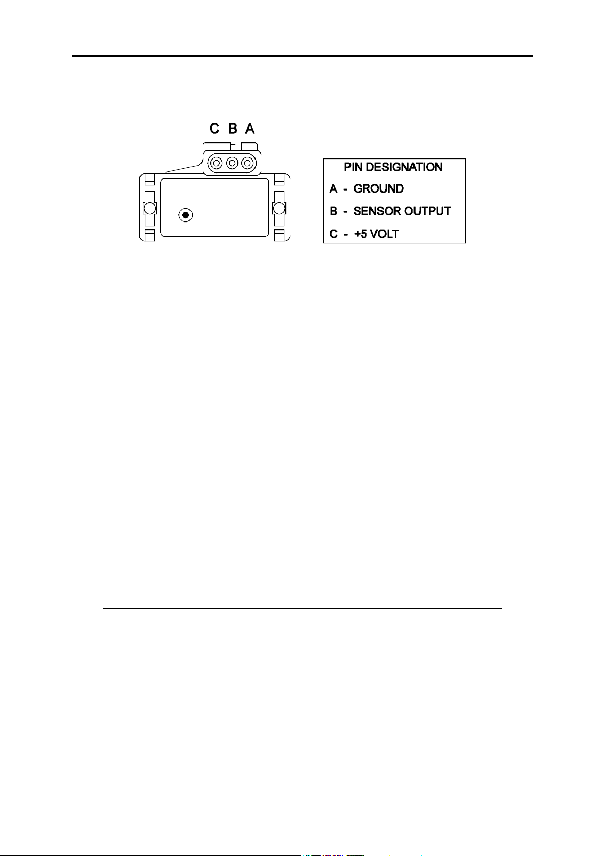
1.3.1 Manifold Absolute Pressure (MAP) Sensor
The MAP sensor is used to convert the manifold pressure into an electrical signal for the ECU
to use. The MAP sensor is used to measure engine load or barometric pressure depending on
the application. The sensor works in absolute pressure that means when the sensor is used to
measure manifold pressure, the pressure reading in the manifold does not need compensation
due to changes in barometric pressure. Since the MAP sensor is an absolute pressure sensor it
can be used in some situations to measure changes in barometric pressure that in some
applications will have a great affect on air-fuel mixtures (Refer Barometric Correction, p62).
There are three types of MAP sensors that can be used with the ECU. The sensor required
depends on the engine set-up.
1 Bar Sensor (Part No.: 039 4070, 16137039 or 12569240)
(-100kPa to 0 kPa) Normally Aspirated Engines
2 Bar Sensor (Part No.: 886 3189 or 16254539)
(-100kPa to 100kPa) Turbo or Supercharged
Engines up to 100kPa boost
(15 psi , 1 atmosphere)
3 Bar Sensor (Part No.: 749 3169, 16040749 or 12223861)
(-100kPa to 200kPa) Turbo or Supercharged
Engines up to 200kPa boost
(30 Psi, 2 atmospheres)
Note: Make sure you have the correct MAP sensor for your engine. The first
three digits of the part number are stamped on the sensor housing.
Engines that use Manifold Pressure as a load reference require an appropriate
MAP sensor to be connected to the MAP Input plug on the wiring loom.
Engines that use Throttle position load sensing do not need a MAP sensor to
measure Manifold pressure but require barometric correction. A MAP sensor
can be used for barometric compensation in the place of the barometric
pressure sensor inside the ECU. This MAP sensor must be a 1 Bar MAP
sensor (left open to atmosphere) and is connected to the Spare Input plug near
the Main Connector. For more information about barometric compensation
(Refer Barometric Correction, p62)
12
Page 13
F10X Manual
Mounting
The MAP sensor is usually mounted high on the engine bay firewall or inner guard using two
screws and with the hose nipple facing outwards. Connect the sensor to the inlet manifold via
a short length of vacuum hose and fasten with either hose clamps or nylon cable ties. Connect
the sensor to the main wiring harness using the appropriate plug. (For 1 Bar sensors the plug
is green, for 2 and 3 Bar sensors the plug is orange). Avoid mounting the sensor below the
level of the fuel injectors, because fuel may collect in the vacuum hose and run down into the
sensor. The sensor assembly is weather-proof but it is good practice to mount the sensor in a
protected position away from moisture and heat.
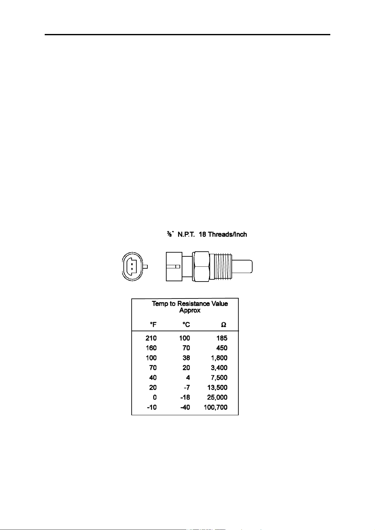
1.3.2 Coolant Temperature Sensor
The ECU uses the coolant temperature to determine warm up corrections to adjust fuel
mixtures.
The coolant temperature sensor has a solid brass temperature-sensing tip. The coolant sensor
supplied is an industry standard component and some engines may already have provision for
this type of sensor.
The coolant temperature sensor is designed to screw into a threaded hole and protrude into the
engine coolant stream. For air-cooled engines, the sensor can be embedded directly into the
engine block or used to sense oil temperature.
Locate a suitable position on the engine which will allow the hole and thread to be machined,
and which gives access to the coolant stream. The sensor should be mounted after the engine
and before the thermostat in the coolant circuit. Since most engines have existing temperature
13
Page 14
F10X Manual
sensor holes, it is often possible to mount the Haltech sensor in one of these holes. A thread
adapter is sometimes necessary. In some engines only one temperature sensor hole exists and
is used for the dashboard gauge sender. It is usually possible to install a tee-piece to allow
both the dashboard sender and the Haltech sender to share access to the same threaded hole.
If it is necessary to drain the coolant from the vehicle to fit the temperature sensor then the
factory manual for the engine should be consulted for the correct procedure to restore the
coolant and purge the cooling system of air.
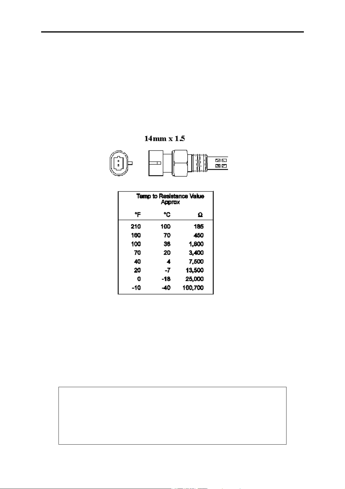
1.3.3 Inlet Air Temperature Sensor
The air temperature sensor is used to compensate for changes in air density due to air
temperature. Cold air is denser than warm air and therefore requires a greater volume of fuel
to maintain the same air/fuel ratio. This effect is most noticeable in forced induction engines.
The ECU will automatically compensate using the signal received from the air temperature
sensor.
The sensor should be mounted to provide the best representation of the actual temperature of
the air entering the combustion chamber, i.e. after any turbo or supercharger, and intercooler,
and as close to the head as possible. The sensor needs to be in the moving air stream to give
fast response times and reduce heat-soak effects.
Note: The Haltech air temperature sensor will read temperatures up to 120°C,
temperatures above this will be interpreted as a fault condition. The air
temperature after some turbos and superchargers can exceed this. If this occurs
with your engine you should consider fitting an intercooler to reduce air
temperature and increase charge density. If this is not possible then the air
temperature sensor should be placed upstream of the turbo or supercharger to
monitor ambient air temperature.
14
Page 15
F10X Manual
Once a suitable position has been located for the air temperature sensor a hole should be
drilled and tapped to accept the sensor. Remove the manifold or inlet tract from the engine
before machining the sensor mount. Do not allow any metal particles to enter the inlet
manifold of the engine as these will be drawn into the engine and damage it. Wash all
components before reassembly.
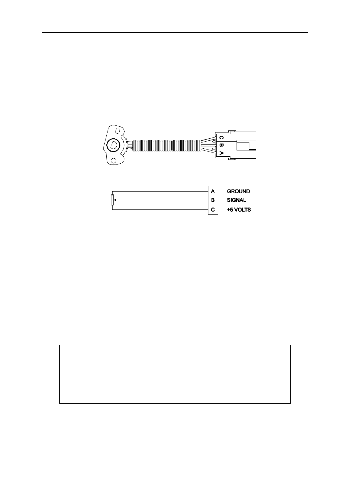
1.3.4 The Throttle Position Sensor (TPS)
The throttle position sensor is mounted to the throttle butterfly shaft to measure its rotation. A
TPS is common on many late model engines and maybe compatible with the Haltech ECU, if
it is not, the Haltech sensor should attach with little or no modification. The throttle shaft
must protrude from the side of the throttle body. This may require the machining of the
throttle body or the manufacture of a new throttle shaft. The inner mechanism of the sensor
rotates with the shaft. If the shaft is round then file a flat surface on the shaft so that it will
pass through the sensor assembly. The TPS should be mounted against the side of the throttle
body, using two screws, such that the throttle shaft and the sensor mechanism can rotate
freely. The absolute range of sensor movement is not important as the sensor can be
calibrated using the programming software.
Your engine may have a Throttle position sensor already fitted and it is often possible to make
use of this TPS. The Haltech supplied TPS has a resistance value ranging from 0 to 10kΩ.
The resistance value of the installed TPS does not have to be the same since the ECU uses a
throttle calibration function to determine actual throttle position.
Note:
Be sure to wire the TPS so that The Engine Data page shows “0%” for throttle
position when the throttle is closed. (Refer to 6.1 Calibrating the Throttle
Position Sensor, p53)
Make sure that the axis of rotation of the shaft is exactly aligned with the axis
of rotation of the sensor. Also, do not use the TPS as a throttle stop. In either
case, the TPS will be damaged.
15
Page 16

F10X Manual
1.3.5 Mount Optional Exhaust Gas Oxygen Sensor
The optional exhaust gas oxygen sensor must be mounted in the exhaust pipe near the exhaust
header or extractors, usually after the collector. The sensor uses the exhaust gas to detect if
the engine is lean or rich. Many late model engines already have provision for an exhaust gas
oxygen sensor and the sensor provided should fit any standard exhaust mount. Some exhaust
systems have the sensor mount up to around half a meter (2 feet) down stream from the
exhaust headers.
If the exhaust system does not have an existing sensor mount then a new mount will have to
be welded to the exhaust system.
When routing the electrical connections to the exhaust gas oxygen sensor do not allow the
harness to touch the exhaust pipe, as the heat will damage them.
1.3.6 Route Wiring Harness and Connect Sensors
Lay the main wiring harness out in the engine bay with the sensors mounted to ascertain the
best fit for the harness. Pass the wiring loom through a hole in the engine bay firewall and
into the passenger compartment where the ECU will be mounted. Either use an existing hole
or cut a new hole to suit. Use a rubber grommet or similar device to protect the harness from
being damaged by rubbing on the sharp edge of the hole.
WARNING:
DO NOT ALLOW THE HARNESS TO TOUCH HOT EXHAUST
PARTS INCLUDING MANIFOLDS OR TURBOCHARGERS.
TRY TO ROUTE THE MAIN HARNESS AWAY FROM HIGH
VOLTAGE IGNITION LEADS. UNDER NO CIRCUMSTANCES RUN
ANY WIRING PARALLEL TO, OR IN CONTACT WITH THE
IGNITION LEADS.
Note: Be neat. Run the harness in a tidy fashion. Try to run the harness along
paths used by original wiring. Use nylon cable ties to secure the harness in
place, but do not stress the wiring or connectors.
Once the harness is fitted, connect all the sensors to their appropriate plugs.
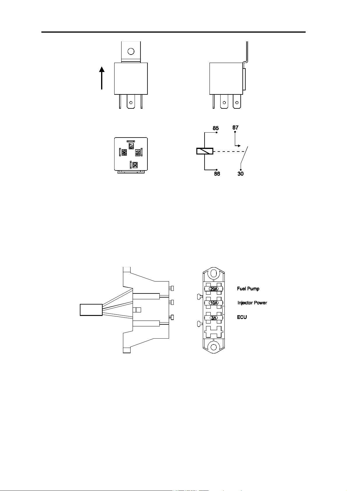
1.3.7 Power Relays
There are two relays used with the ECU, the Main Power Relay (with a grey wire) and the
Fuel Pump Relay (two orange wires). These relays are identical parts so it is not important
which relay goes in what connector.
16
Page 17
F10X Manual
These relays should be mounted on the firewall or an inner guard. Do not mount the relays
such that they could catch and collect splashed water. Residual water inside the relay housing
will cause them to fail. Mount them with the tab upwards as shown in the diagram.
1.3.8 Fuse Block Assembly
The fuse block assembly holds the fuses that protect the various components of the Haltech
system.
The fuse block is supplied from the factory with fuses installed. The fuse ratings are shown in
the diagram and should not be changed except in special circumstances, as these have been
selected for best protection. In some applications where multiple low impedance injectors are
being used, the main 3A ECU fuse may blow. In such applications, please replace this fuse
with a 10A fuse.
The fuse block should be positioned so that it can be easily accessed in case of fuse failure.
Do not mount the fuse block where it could be exposed to water. Mount via the two screws
holes in the block. Ensure that vibration will not cause the screws to vibrate loose.
17
Page 18

F10X Manual
Connect the Fuse Block assembly to the Main Harness.
1.3.9 Electronic Control Unit (ECU)
The ECU is not designed to be waterproof. It is desirable that the ECU be given as much
protection from the environment as possible. It is recommended that the ECU be mounted
inside the passenger compartment, either on the firewall, under the dashboard or under the
passenger seat.
The ECU has four mounting holes that allow it to be mounted to most flat surfaces. In
extreme cases of vibration, the ECU should be mounted on rubber anti-vibration pads. When
mounting the ECU remember that the communications connector on the loom should remain
accessible for ease of programming.
1.3.10 Flying Leads
Locate and connect the following flying leads.
Black (Ground)
Locate a good chassis ground point and connect the black wire.
Red
(Battery Supply +12V) Locate a source of continuous +12 volts and connect the red
wire. Connecting direct to the positive battery terminal is suggested.
Grey
(Ignition Switched +12V) The grey wire is used to control the operation of the ECU
power relay. It needs to be connected so that it sees 12V only when the ignition switch
is on and during cranking. This wire does not draw a large amount of current (< 0.5A).
Do not connect to the accessory outputs of the ignition switch since +12V is not
available during cranking in many cases.
Green
(Aux In) The green wire is used as the Aux In channel. The Aux In channel is used by
a number of functions and is further described in 4.2.4 The In/Out Set-up Page, p39)
The following diagram is an example of how to wire the Aux In circuit:
NOS, Anti-lag, Flat-Shift
Switch, etc
Aux In
GND
18
Page 19
F10X Manual
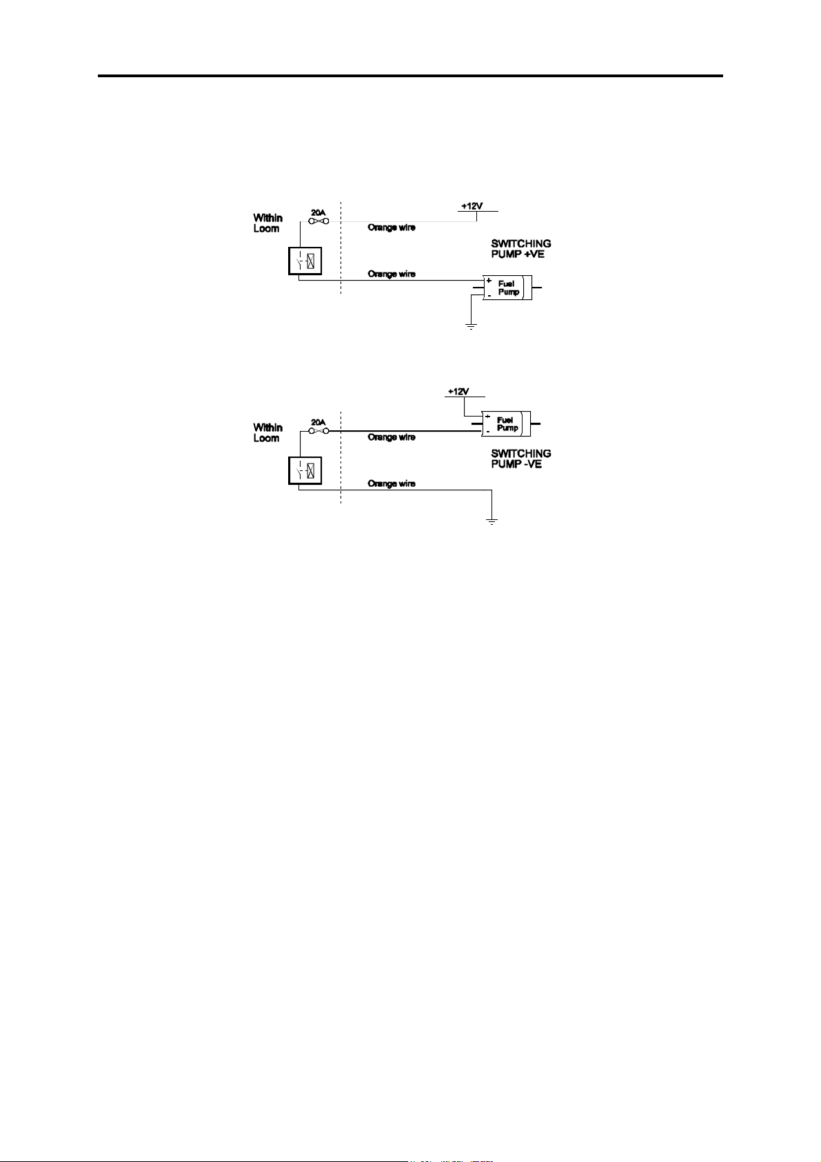
Orange
The two orange wires are used to operate the fuel pump. When the ECU wants to
operate the fuel pump it will close the fuel pump relay connecting the two orange
wires together. The diagrams show two examples of wiring the fuel pump. Do not add
extra relays to the fuel pump circuit.
Example 1: Conne cting to the po s itive s ide of the f ue l pump.
Example 2: Conne cting to the ne gative side of the f ue l pump.
It does not matter which example is used, as both will operate correctly. Note that the orange
wires are connected internally within the loom when the relay is closed. As a result it does not
matter which orange wire is used to connect to the fuel pump.
1.3.11 Install and Connect Optional Idle Speed Motor
If you are not using the Idle Speed Control, tie the loom connector back neatly in the engine
bay. If the engine has a suitable Idle Speed Motor then you may connect it to the wiring loom,
otherwise you can install a Haltech supplied idle air control motor.
1.3.12 Install and Connect any Optional Outputs
If you are planning to use any of the Programmable Optional Outputs, install and connect
them now. Depending on what options you are using, the wiring will be different. For details
on wiring your particular options, refer to CHAPTER 12 Digital Outputs & PWM Outputs,
p79.
19
Page 20

F10X Manual
1.3.13 Connect the Trigger Sensor
The Trigger is used by the ECU to determine Engine Speed and Position.
When connecting the trigger (crank or cam position) sensors it is important to identify the
type of sensor being used to measure engine speed and position from the following options:
Optical, Hall Effect or Coil Negative.
Optical and Hall effect Triggers
Optical and Hall effect triggers behave in a similar way and are treated the same by the ECU
and the term “Hall Effect” should be taken to include Optical triggers.
Hall Effect triggers generally have 3 connections: power, ground and signal and the output of
the sensor is a square wave digital signal.
Coil Negative Trigger
The F10X can be triggered by the signal found on the negative side of an Ignition Coil. The
F10X has a sole purpose input wire for this signal called “Negative Coil” which is Pin 36 on
the F10X ECU. Please make sure that in the Trigger Setup page, the Trigger Type is set to
Coil Negative if this type of trigger is to be used.
Tacho Output Trigger
Some popular ignition systems have a tacho output signal, which can be used to trigger the
F10X through the Coil Negative Trigger Input. It is necessary to use this tacho output if the
ignition system used is a Capacitive Discharge Ignition System with multiple spark function.
For more information on trigger systems Refer to Appendix E
1.3.14 Connect the ECU
The ECU can now be connected, be sure to engage the clip on the main connector. The
system can now be tested as described in the following chapters.
20
Page 21

F10X Manual
CHAPTER 2 INSTALLING THE SOFTWARE
Now that your ECU is installed the programming software must be installed so that tuning
can begin.
This Chapter will explain how to install and run HalwinX, the Haltech Programming
Software.
2.1 Computer Requirements
HalwinX requires a PC running Windows 95 release 2, Windows 98, Windows 2000,
Windows Millennium or Windows XP with the following specifications.
Minimum Requirements:
233MHz processor
VGA colour display 800x600 (preferably 1024x768)
4 MB of memory
10 MB of free Disk space
Recommended:
PIII 500MHz processor
VGA colour display 1024x768
16 MB of memory
10 MB of free Disk space
2.2 Operating the Software
2.2.1 Installing the Software
Installing Halwin onto your PC is performed similar to any other Windows software package.
Installation is outlined below to ensure correct installation:
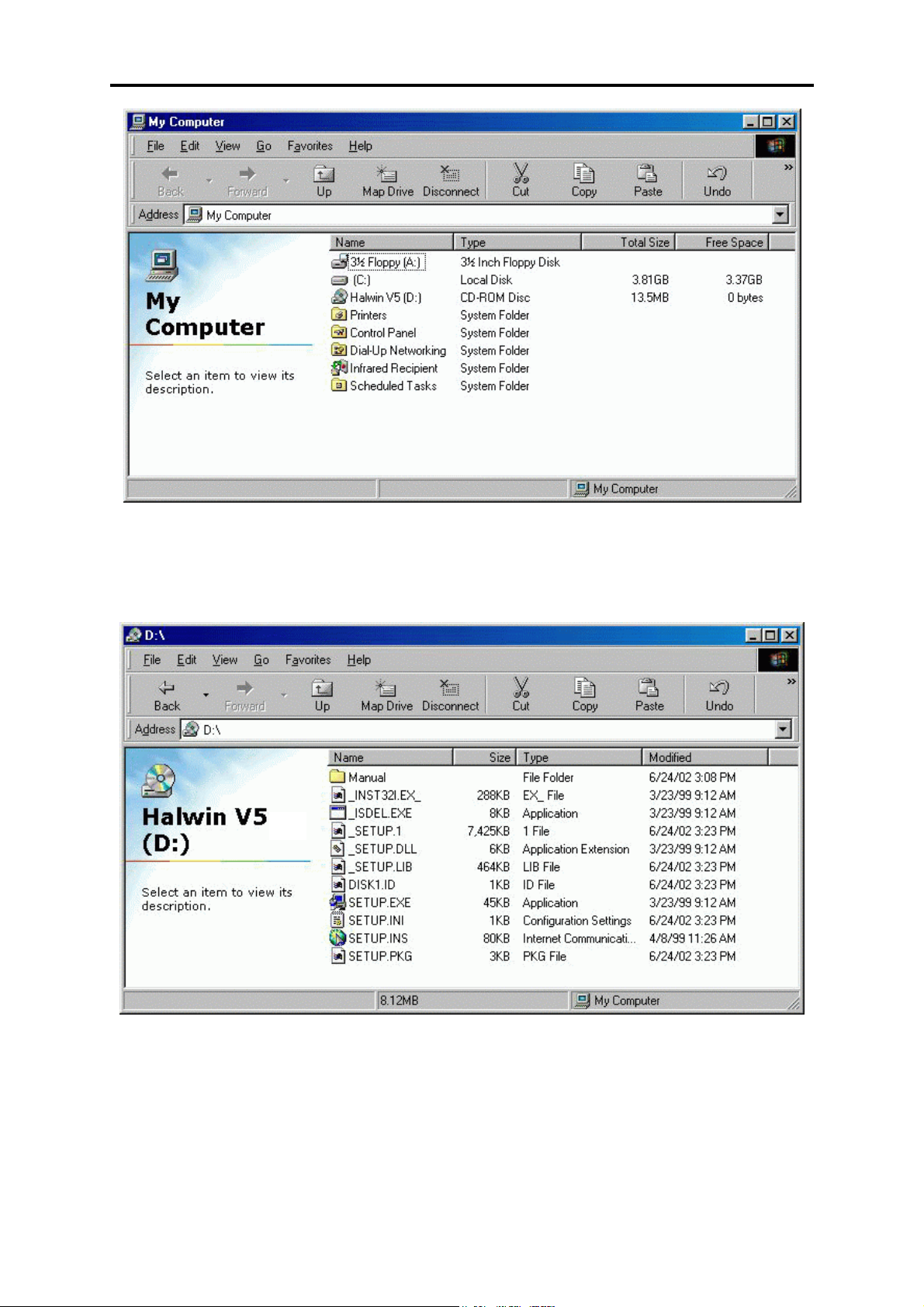
1. Insert the CD-ROM into your PC’s CD-ROM drive.
2. Double click on the “My Computer” icon on the
desktop
21
Page 22
F10X Manual
3. Double click on the CD-ROM icon to open the CD-ROM. If the setup software does
not automatically open, then double click on the “SETUP.EXE” icon to start the setup
software.
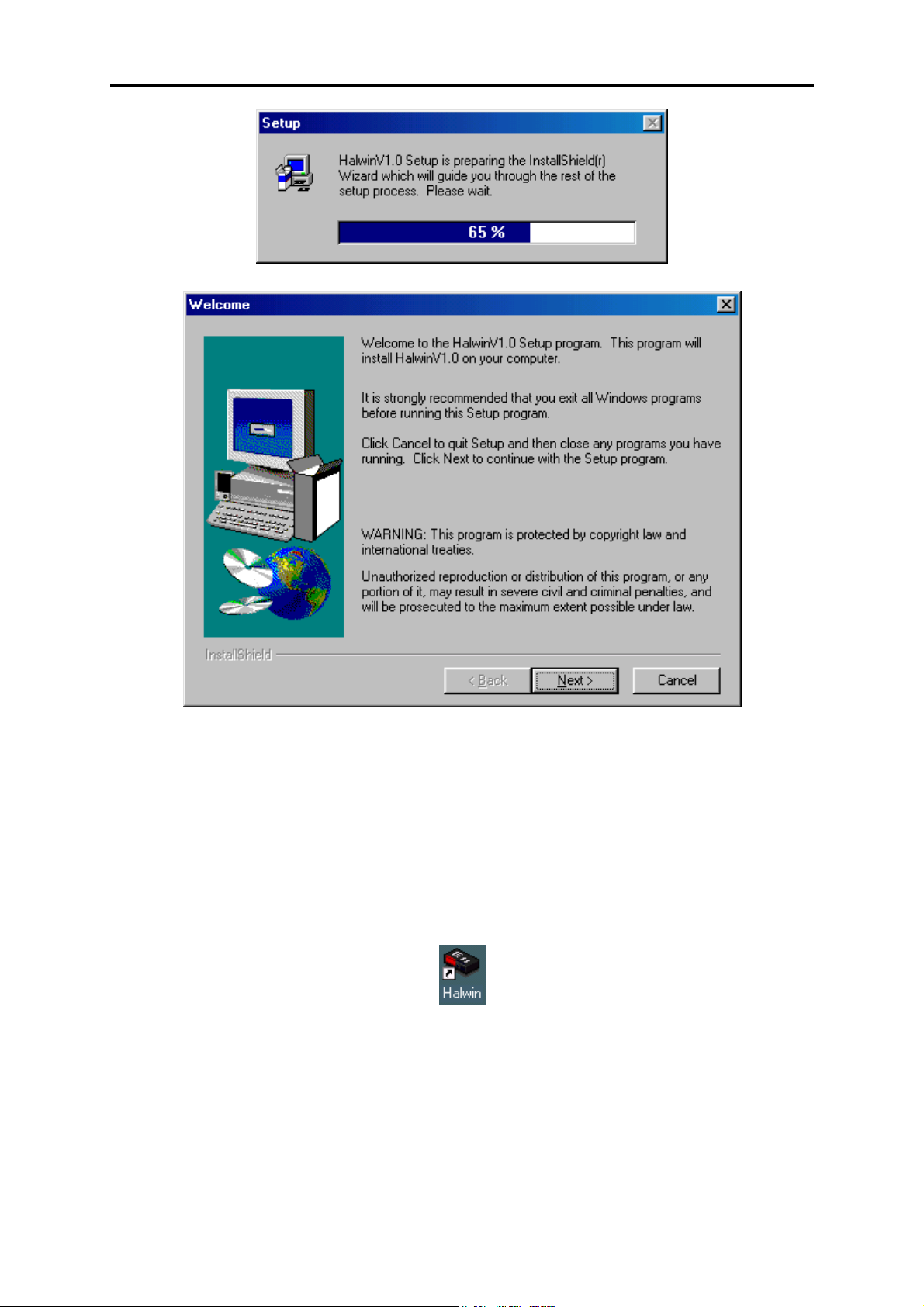
4. After double clicking on the ‘SETUP.EXE’ icon, the following screens will appear.
22
Page 23
F10X Manual
5. Click on ‘Next >’ to continue and follow the instructions given to you on the windows
that appear.
6. When prompted for which type of installation to perform, choose ‘Typical’ if you are
unsure.
2.2.2 Running the Software
After installing the software, an icon should appear on your desktop similar to the one shown
in the picture below.
Double click on the icon to start Halwin.
23
Page 24

F10X Manual
CHAPTER 3 OPERATING THE SOFTWARE
Once the ECU is installed, the programming software allows the user to change the settings
currently stored in the ECU. The ECU requires information about the engine it is to operate
such as:
- Number of cylinders (or rotors): it needs this to calculate engine speed, ignition timing
and fuel quantity
- Engine Type: Piston or Rotary, the ECU requires this information since the ignition
system for a rotary engine is significantly different from that of a piston engine.
This information is called set-up information.
The ECU also requires information about the amount of fuel or ignition timing it must supply
based on various engine-operating conditions. An example of this is the amount of fuel the
engine requires based on the current intake air temperature, this information is stored in a
“Map”. As the intake air temperature changes so do the fuel requirements of the engine, so
the ECU has data for the amount of fuel injected for various different temperatures, this set of
data is known as a “Map”. These ideas of data storage are discussed further in CHAPTER 4
Configuring the ECU, p34 and CHAPTER 5 Haltech Maps, p43
3.1 The Menu Structure
All of the windows, maps and settings can be accessed via the menu shown at the top of the
Halwin software screen. These menus can be accessed in the usual methods with the mouse or
by keyboard
To access the menus via keyboard press and hold ALT and then Press the key corresponding
to the first letter of the menu title which you wish to access F, M, S or O. This will cause a
menu to appear from which a series of menu item are available. To choose a menu item use
the up and down cursor keys:
↑↑↑↑, ↓↓↓↓
When the desired menu item is highlighted:
Press Enter
When a key combination like:
Press and Hold ALT and then Press F
Is required it will be abbreviated in the manual to ALT-F.
The following describes the individual Menus and their contents.
3.1.1 The File Menu
To open the File menu Press ALT-F or alternatively use the mouse to select the File menu.
The file menu contains the following items:
- Load From File
- Load E6K/F10/E6GM Fuel and Ignition Maps
- Save to File
- Quit (Ctrl Q)
24
Page 25
F10X Manual
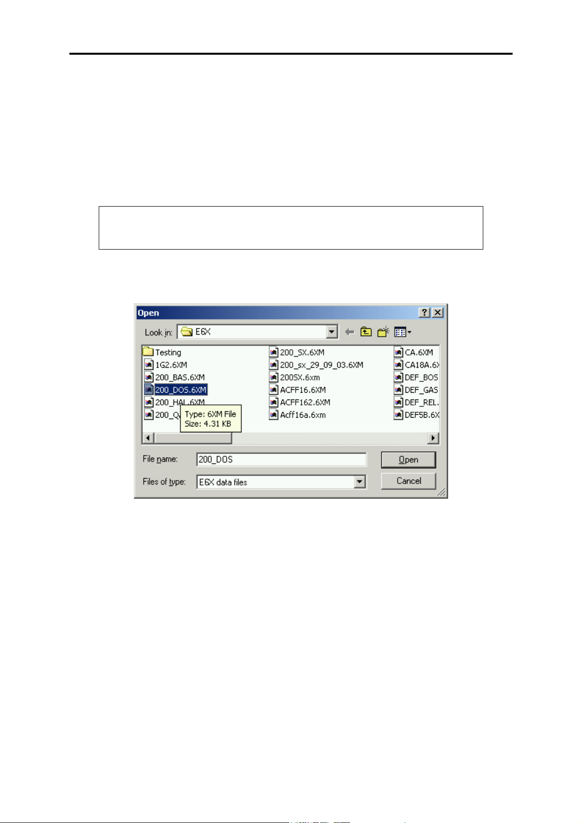
3.1.1.1 Load From File
Load From File allows the user to load a file that contains all the “set-up” and “map” data the
ECU requires to run a particular engine. This file has been saved during a previous tuning
session when the programming PC was connected to the ECU. When the ECU is “Offline”,
the Load Map function can be used to load the information from an F10X map file (denoted
by the .6XM file extension) into the front-end software to view its contents. If the ECU is
“Online” using the Load Map function will cause the ECU to be loaded with the information
stored in the file and all information previously stored in the ECU will be lost.
NOTE:
When using the load function be aware that when the ECU is online all “set-
up” and “map” data currently stored in the ECU will be overwritten.
To choose the desired map simply select the desired file from the dialog and press enter. This
is illustrated below,
The selected filename will be displayed in the horizontal black bar below the text “ Opening
File”:
Press Enter
When the ECU is “Online” the central Status Bar will turn red and indicate the load status of
the map.
3.1.1.2 Save To File
The ECU programming software allows the user to save all the information in the ECU to a
file on the programming PC. This allows the user to save a map and continue tuning and
then, if required, revert to a previous map.
25
Page 26
F10X Manual
NOTE:
When the save function is used it saves the current map loaded in the
programming software. If the ECU is “Offline” the map available in the
programming software may not be the map that is stored in the ECU.
When you choose the “Save To File” menu item a file dialog similar to the Load map will be
displayed. In this case you navigate to the directory of your choosing and type in the filename
of your choice.
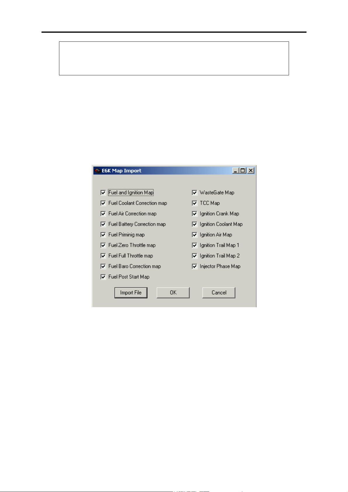
3.1.1.3 Load E6K/F10/E6GM Fuel Maps
This option allows the user to import all the fuel and ignition maps from an E6K/F10/E6GM
into the F10X user map. To select this the user selects File -> Load Fuel Maps. The following
form shall be displayed to the user,
The user selects the maps they wish to import by selecting the appropriate items by clicking
on them. In the example shown above all items have been selected. Once the user has selected
the items needed, the user clicks on the Import File button. This brings up the file dialog box
and the user selects the desired unit file. Please note: this feature will only import maps and
NOT set up details.
3.1.1.4 Quit
Quit allows the user to leave the programming software and return to the operating system.
The user can also quit the software using the quit “Hot-Key”:
Press CRTL-Q
26
Page 27
F10X Manual
3.1.2 The Map Menu
The map menu allows access to the maps contained in the ECU. The following is a
description of the map menu and is not a complete description of the maps, for more
information on all the maps available and their function refer to CHAPTER 5 Haltech Maps,
p46.
To open the map menu Press ALT-M.
The map menu contains the following items:
- Fuel Map CTRL-F – 2D View, CTRL – ALT - F – 3D View
- Fuel Correction Maps
- Zero Throttle Map
- Full Throttle Map
- Injector Phase Map
- Waste-gate Map 1
- Waste-gate Map 2
- Torque Converter Map
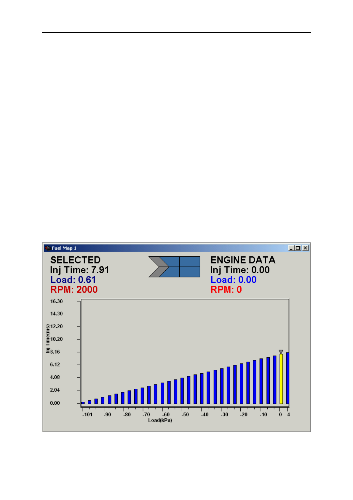
3.1.2.1 Fuel Maps
The Fuel Map is constructed of individual ranges containing Injector Pulse Width against
Engine Load as shown below.
The individual ranges represent different engine speeds; in the example above the map shown
is from the 2000rpm range.
27
Page 28
F10X Manual
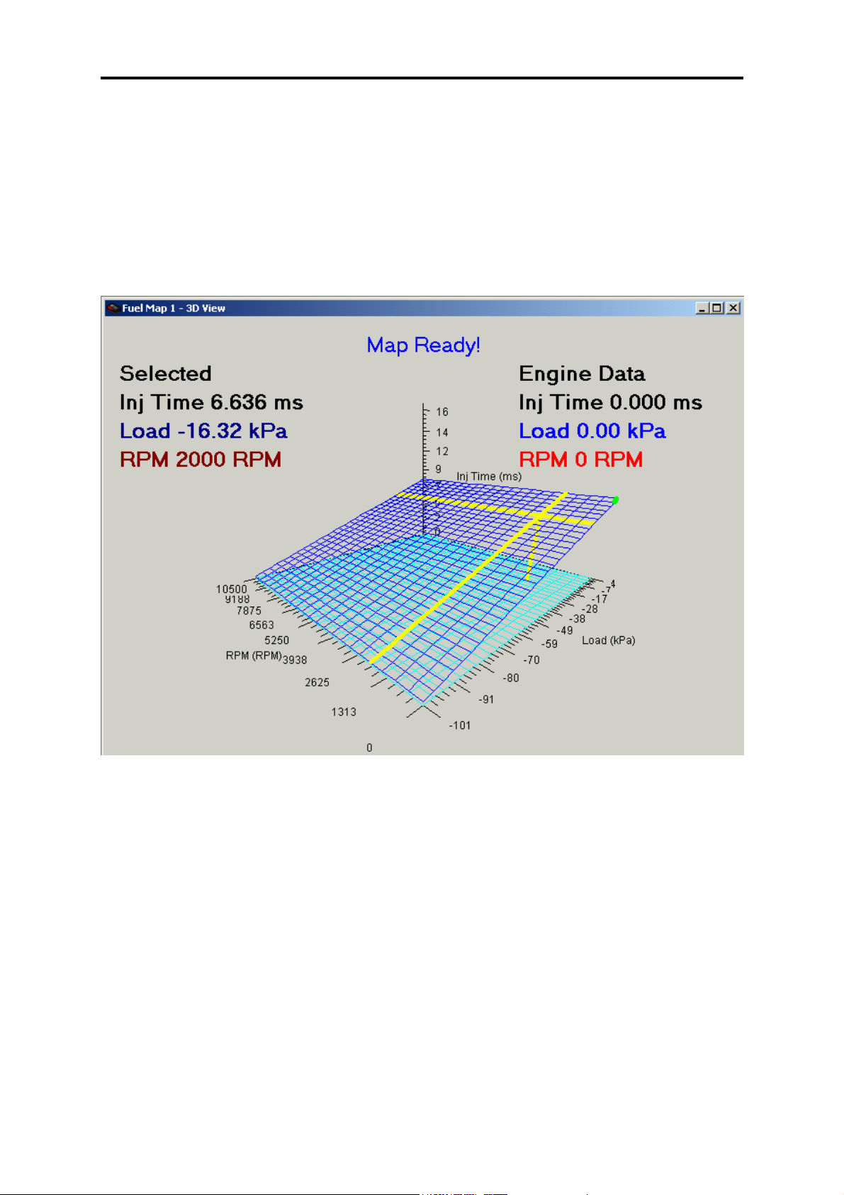
The Fuel map menu item will open a sub-menu which allows access to all the fuel map ranges
from 0 –8500rpm. The keys:
N for Next and
P for previous
Allow the user to cycle through all the available rpm ranges and allows access to the rpm
ranges not accessible via the sub-menu.
The 3D view is shown below,
To go through the load ranges the user uses the left and right arrow keys. To cycle through the
RPM range the user uses the up and down arrow keys. To select multiple bars the user presses
the Ctrl arrow keys to select the bars they wish to tune. To change the bars the user can use
“a” and “s” to change the fine increments and Pg-Up and Pg-Down for the rest of the
increments.
28
Page 29

F10X Manual
3.1.2.2 Fuel Correction Maps
Fuel correction maps allow the ECU to calculate corrections to the amount of fuel injected
based on the information received from the engine sensors.
The fuel correction maps menu item will open a sub-menu that allows access the fuel
correction maps:
- Coolant Temperature
- Air Temperature
- Battery Voltage
- Coolant Temperature Prime
- Post Start
- Barometric Pressure
- Gas Temperature (used for Gas (LPG or similar) fuel vehicles)
- Gas Pressure (used for Gas (LPG or similar) fuel vehicles)
The Set-up Menu
The set-up menu allows access to the ECU set-up pages (which contain most of the
information about the engine that the ECU is to control) and the program set-up page.
The set-up menu contains:
- Main Set-up CTRL-M
- Fuel Set-up
- Trigger Setup
- In/Out Set-up
- Throttle Setup
- ComPort Setup
- Set Password
- Screen Colour
3.1.3 The Options Menu
The options menu allows access to the option pages. The options set-up pages allow the user
to modify the setting for idle control, closed loop O2 Control and the 4 PWM channels and
any available digital outputs.
The options menu contains:
- Idle Speed Control
- Closed Loop O
- PWM and Digital Output options
- Throttle Pump
- Injector trims
- Log Data (CTRL – D)
- View Data Log
Further description of the contents of the options menu is distributed throughout the manual.
control
2
29
Page 30
F10X Manual
3.1.4 Data Page Menu
This allows the user to access the engine data in online mode so they can deduce how their
engine is performing. The menus that access this are,
- Gauge Page
- Engine Data page.
- Firmware Version Info.
These shall be discussed in detail further on.
3.1.5 Password Protection
The maps in the ECU can be password protected at the user’s choice. To Set the password the
user selects Setup-> Set Password where the user must enter an 8 character password such as
“haltech1” or “Beatrice”. The user must use an 8 character password and this password is case
sensitive. The dialog for this is illustrated below, and is activated by pressing OK.
If at any time the user wishes to remove the password protection, they may do so by selecting
Setup-> Null Password.
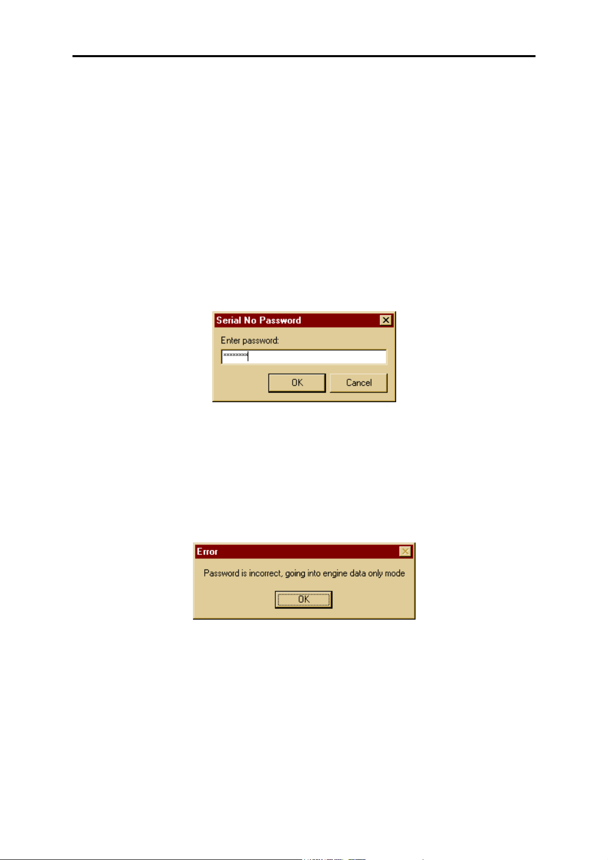
When a ECU that has been password protected is first connecting to the laptop, the data will
transfer 99% of the data before prompting the user for the password to continue. If the
password is correct, the user will be given full access to the ECU, if the password is incorrect,
the user will only be given access to Data pages and diagnostic data.
30
Page 31

F10X Manual
3.2 Online and Offline Operation
The programming software can be used in two ways: “Online” and “Offline”. In the Online
mode, all the changes made to the maps and set-up data in the software will be transmitted to
the ECU. This is what is called online programming and it is in this mode that most tuning is
carried out. In the offline mode, making changes to the maps and set-up data will not affect
the ECU since communication between the programming PC and the ECU is not active.
Working in the offline mode is a convenient way of checking maps that have been stored to
disk and reviewing Data-logs that were taken when in the Online mode.
It is advised that first time users familiarise themselves with the software in the “Offline”
mode before “Online” operation is attempted. Most features of the software are available in
the “Offline” mode so that the user can learn the controls for navigating the software. The
only features not available “Offline” are: The Engine Data Page and the Calibrate Throttle
function, these features require communications with the ECU.
The Software can be identified as “Online” or “Offline” by the label in the middle status bar
that indicates whether the software is on or offline. The other indicator is the Go –
Offline/Online button. When offline the button displays Go – Online. When online the button
displays Go offline.
NOTE:
For changes made in software to be transmitted to the ECU the programming
software should be online.
3.2.1 Going Online
To go “Online” the ECU must have power and there must be a RS-232 communications cable
(supplied with most kits) connected to the ECU loom and the programming PC.
Start the programming software and the following will appear:
31
Page 32

F10X Manual
Press the Go Online button in the top left hand corner. This will start communications with
the ECU. The Status bar will indicate the load status, which is illustrated below,
Status
Bar
When the progress bar reaches 100% the programming software has finished uploading the
data from the ECU and the status bar will show “HALTECH CONNECTED” and the status
bar will be blue. If the text “HALTECH DISCONNECTED” flashes this means that the
programming PC cannot communicate with the ECU, check:
- The ECU has power
- The communications cable is connected
- The communications cable is free from faults
3.2.2 The Engine Data and Gauge Page
The Engine Data page, as its title suggests, displays engine information in real time so the
user knows the operating conditions of the engine at all times. The engine data page can be
used to test that the ECU and its sensors are working correctly. There are two forms of the
Engine Data page, the Text view and the gauge page. Both views are shown below,
32
Page 33

F10X Manual
3.3 Hot Key Summary
Many of the menu items have shortcut keys or “Hot Keys” which allow the user to access a
menu item directly from anywhere in the programming software eliminating the need to
navigate the menu structure. These “Hot Keys” are as follows:
- CTRL-Q - Quit the Programming Software
- CTRL-F - Fuel Maps
- CTRL-M - Main Set-up
- CTRL-G - Gauge Page
- CTRL-E - Engine Data Page
- CTRL-O - Output Options
- CTRL-T - Throttle Pump
- CTRL-D - Data log
33
Page 34

F10X Manual
CHAPTER 4 CONFIGURING THE ECU
4.1 Using the ECU Set-up Pages
The Set-up pages of the programming software tell the ECU essential information about the
engine which it is to control.
NOTE:
The set-up pages are where tuning should begin, it is important to configure
the ECU before any attempt is made to start and operate the engine.
Each setup page consists of dialog boxes where the user enters the desired values and settings.
To navigate between the settings the user can use the mouse or press the Tab key and either
types in the required value or presses on a check boxes. To apply the changes the user presses
the Enter key or clicks on the OK button
4.2 The ECU Set-up Pages
The main set-up pages that define the way the ECU operate. These are:
- Main Set-up
- Trigger Set-up
- Fuel Set-up
- In/Out Set-up
- Ignition Set-up
These set-up pages must be configured before the engine is even started to insure the
following: the engine will run, no damage will be caused to the engine or engine components
and no damage will be caused to the ECU. In addition to these set-up pages are the options
set-up pages that configure the following: idle control, closed loop O2 control and the PWM
outputs. These outputs are not critical to starting the engine and are usually left until the
engine has been roughly tuned to allow it to idle.
4.2.1 Main Set-up Page
The main set-up page contains basic engine information. The Main Set-up Page is accessed
via the set-up menu or using: CTRL-M from anywhere in the programming software.
The fields in the main set-up page are as follows:
Cylinders
The number of cylinders needs to be entered here. This parameter is used to determine
the engine speed and other fuel and ignition requirements.
Load Sensing
The ECU can use either the manifold pressure or the throttle position as a means of
determining the engine load. Most engines operate using manifold pressure to sense
engine load. If your engine employs any form of forced induction, you must run in
manifold pressure mode. Only engine with long duration cams or multiple throttle
bodies, motorbikes or heavily ported rotaries require throttle mode - i.e. Engines
34
Page 35

F10X Manual
whose vacuum signal is small, or fluctuates greatly. If you are unsure what to use,
contact your Haltech dealer.
MAP Sensor
The ECU needs to know the type of Manifold Absolute Pressure (MAP) sensor being
used. If you do not know what sensor you have refer to 1.3.1 Manifold Absolute
Pressure (MAP) Sensor, p12. Enter the correct description here to match. If using
throttle position mode, set this parameter to a 1 Bar sensor.
RPM Limit
The ECU can limit the maximum rpm at which the engine will operate. Above this
level the ECU completely cuts fuel or ignition (see below) to the engine. When the
engine speed drops below the RPM Limit the F10X will resume normal fuel delivery.
This is known as hard limiting. If the RPM Limit is not needed then set this value
above the highest operating point of the engine.
Road Speed Value
This value calibrates the Road Speed reading. The value represents the number of
pulses received from the road-speed sensor over a distance of 1 km.
Rotary/Cylinder mode
This allows the user to choose between whether they are running a rotary or cylinder
mode.
RPM Limit Type
The RPM Limit can only be set to fuel cut for this unit.
Units
The programming software can display parameters in either Metric or US units. At
present HalwinX is fixed to SI units.
RPM Mode
The ECU fuel maps may be arranged either in 500 rpm increments from 0 rpm to
10,500 rpm, or in 1000 rpm increments from 0 rpm to 16,000 rpm. Select the high or
low rpm mode here. Changing this setting alters the way the ECU reads the fuel
Maps, and will change the tuning of the engine dramatically.
ECU Mode
The user has the option to choose between basic and advanced mode. This is a legacy
component from the DOS software and the user is advised to choose advanced mode.
Dual Map Setup
This allows the user to switch between Fuel map 1 and Fuel map 2. If Dual Map
disable is selected, Fuel map 1 is selected.
Use of Secondary Map
This defines the method by which the ECU determines which base map to use. The
options are:
Never This causes the ECU to only use the primary base fuel
map.
35
Page 36

F10X Manual
Always This causes the ECU to only use the secondary base fuel
map.
Enable with Aux. In This causes the ECU to use the primary base fuel map
when the Aux. In is not connected to ground. The ECU
uses the secondary base fuel map when the Aux. In is
connected to ground.
Note:
The Aux. In field in the Input/Output Set-up page must be set to Dual Maps
Input. Refer to 4.2.4 The In/Out Set-up Page, p39
Enable with VTECH This causes the ECU to use the primary base fuel map
when the VTECH Output is inactive. The ECU uses the
secondary base fuel map when the VTECH Output is
active.
Use of Gas Compensation Maps
This field tells the ECU how to use the gas compensation maps.
Note:
The gas compensation maps can only be used if the spare A/D and the Trim
input are configured for gas pressure and gas temperature. Refer to 4.2.4 The
In/Out Set-up Page.
The options are:
Always The gas compensation maps will always be used.
Enable with Aux. In The gas compensation maps will only be used if the Aux.
In. line is connected to ground. The gas compensation
maps will not be used if the Aux. In. line is not connected
to ground.
4.2.2 Fuel Set-up Page
The fuel set-up page contains information about the fuel system. The Fuel Set-up Page is
accessed via the set-up menu.
The fields in the fuel set-up page are as follows:
Decel Cut Enable/Disable
A common fuel saving feature in original equipment computers is a fuel cut-off on
deceleration. This will cut fuel delivery to the engine while coasting down hills with
closed throttle. This feature can be enabled or disabled. It is better, when first tuning,
to disable this function.
Decel Cut RPM
This is the RPM above which the Fuel cut out will be applied.
36
Page 37

F10X Manual
Injection Mode
The ECU can operate in 3 different injection modes depending on the application
these are:
Multipoint injection fires all the injectors together. This is the most common set-up
and will normally be used on engines with multipoint injection manifolds (one injector
per cylinder).
Batch-fire injection is usually used in throttle body or non-turbo rotary set-ups and
fires the two banks of injectors alternately. On eight and twelve injector fuel rails,
with high-flow injectors, this may also help reduce fuel pressure oscillations caused by
all injectors pulsing together.
Staged injection is usually used on high boost turbo engines. Injector outputs 1 and 2
fire all the time, just as in a multipoint set-up. When the boost pressure exceeds a
programmed value, injector outputs 3 and 4 are enabled.
The staged injectors are normally upstream of the primary injectors. The point at
which the ECU switches in the secondary injectors is set via the Staging Bar Number
field which is described below. Staging permits high fuel-flow capability, but
maintains accuracy and controllability at light load and idle.
Enable Injectors
This field allows the user to turn on all injector outputs. Turning this checkbox off will
disable all injector outputs.
Post Start Temp Limit
This field sets the temperature at which the post start correction map is either enabled
or disabled. The following field “Above/Below” sets whether the enabled state
corresponds to a temperature above or below the Post Start Temp Limit. The Post
Start correction map will apply correction to the injection times from when the motor
is started to when the engine temperature reaches the Post Start Temp limit.
Post Start Time Limit
This field sets the period of time across which the Post-start map is to operate.
Ignition Divide By
Ignition Divide By is the number of Ignition / Trigger pulses that will be counted until
the next injection pulse. For almost all multipoint systems, injection should occur once
per revolution so Ignition Divide By should be set to half the number of cylinders. If
the system is operating in Batch Fire mode, or is a rotary, then a value of 1 is
suggested.
Staging Bar Number
This field sets the point at which the staged injectors are enabled. If the injection
mode is not "Staged Injection" then this field will not affect injection.
Zero Throttle Map
This feature allows the user to adjust a special fuel map that is used only when the
throttle is closed. This feature should be used for engines that produce constant
vacuum while cruising but irregular vacuum when idling. The zero-throttle Map can
37
Page 38

F10X Manual
allow simple adjustment of the idle fuel settings. This field enables or disables the use
of this map.
Throttle Pump Dead-band
This field defines the percentage change in throttle position that must occur before the
throttle pump is activated. This feature allows for “jitter” in the throttle that would
otherwise over-fuel the engine. The valid range of values is 1-20%.
Full Throttle Map
This feature allows the user to adjust a special fuel map that is used only when the
throttle is wide open on normally aspirated engines. With some manifold and or
throttle designs, pressures in the manifold can reach close to atmospheric pressure
before full throttle is applied. This effect can make tuning difficult around full
throttle. This map allows the full load settings to be easily set without interfering with
lighter load settings. This field enables or disables the use of this map.
Full Throttle Threshold
This field defines the throttle position at which the ECU considers to be full throttle.
This field can be set between 70 and 100.
Barometric Lock
This field allows the user to base the barometric corrections on a single point in the
barometric correction map. This function is used rather than using the barometric
pressure sensor in the ECU if the spare A/D is required for another purpose. The ECU
now requires the user to provide a barometric pressure value for performing
barometric corrections. This value is programmed via Barometric Pressure Lock at
xxxx (mBars).
Barometric Pressure Lock at xxxx (mBars)
This field contains the barometric pressure value at which the ECU is to be locked if
enabled by the field “Barometric Lock”.
WARNING:
BAROMETRIC CORRECTION IS A POWERFUL TOOL WHEN
USED PROPERLY BUT CAN CAUSE SERIOUS DAMAGE TO
ENGINES WHEN IT IS CONFIGURED INCORRECTLY. FOR A
FULL DESCRIPTION OF THE BAROMETRIC CORRECTION
AVAILABLE WITH THIS ECU REFER TO 9.3 BAROMETRIC
CORRECTION, P62
38
Page 39

F10X Manual
4.2.3 Trigger Setup
Trigger Input Type
This field defines the type of pickup used to trigger the ECU. Select Hall Effect or
Coil Negative/Tacho Output depending on the trigger being used. As both Hall Effect
and optical trigger sensors generate a square wave select Hall Effect for optical
sensors. Please note that the ECU connections will change depending on which trigger
you have.
Hall Effect Trigger = Connect to Pin 6 (Trigger) or Pin B on Connector J16 for
terminated harness.
Coil Negative/Tacho Output Trigger = Connect to Pin 36 (Coil Negative) or Pin C
on Connector J7 for terminated harness.
Trigger Input Pull up options
This field is used to pull-up the voltage of the trigger circuit when in Hall Effect
mode. For most applications, this setting will need to be switched on.
Trigger Edge
The trigger edge defines whether the ECU uses a rising or falling signal from the
pickup. For a further description on trigger edge see
4.2.4 The In/Out Set-up Page
The In/Out set-up page contains the information about auxiliary components the ECU is to
control. The In/Out Set-up Page is accessed via the set-up menu or using: CTRL-N from
anywhere in the programming software.
The fields in the ignition set-up page are as follows:
Trim Control
The optional Trim is a useful tuning and control unit and can be used to control one of
several parameters. If there is nothing connected to the trim plug, the trim will have
no effect (except with boost control). The available functions are:
Fuel (Fine) ±12.5% adjustment of fuel.
Fuel (Coarse) ±50% adjustment of fuel.
Boost Control Boost trim for Waste-gate control only.
BAC2 This trims the idle speed by modifying the duty cycle driving
the BAC valve through PWM 3 or 4 when set to BAC2 Valve
(open loop idle control). When the spare A/D is set to BAC2 it
overrides all BAC2 PWM parameters and drives the channel
with a duty cycle proportional to the trim position.
Spare Input Function
The Spare input is an analogue input similar to the Trim Control input that can be
configured for one of several tasks. The available functions are :
General 0-5 volt input; no effect on ECU operation.
Fuel (Fine ±12.5% adjustment of fuel.
Fuel (Coarse ±50% adjustment of fuel.
39
Page 40

F10X Manual
Baro Sensor Barometric Pressure Sensor (internal/external).
Exhaust MAP Sensor Exhaust Pressure(does not affect ECU operation)
Aux RPM Limit Input switch for activating Aux RPM limit. Limit may be
above/below the primary RPM limit. Useful for launching
or allowing extra RPM momentarily for overtaking.
O2 Sensor Display only (does not affect ECU operation). The reading
appears on the Engine Data Page as mV.
40
Page 41

F10X Manual
WARNING:
WHEN CONFIGURING YOUR SYSTEM TAKE CARE TO SET THE
SPARE INPUT FUNCTION CORRECTLY. IF THE SPARE INPUT
FUNCTION FIELD IS SET TO BARO. SENSOR EXTERNAL AND
THE BARO SENSOR IS DISCONNECTED THE ECU MAY PERFORM
INCORRECT BAROMETRIC CORRECTION. IF YOU ARE USING
AN EXTERNAL BARO SENSOR AND REMOVE IT BE SURE TO
RECONFIGURE THE SPARE INPUT FUNCTION TO GENERAL.
2nd MAP Sensor
This field is only accessible when the Exhaust MAP Sensor is selected on the Spare
Input Function. It tells the software what sensor is being used (either 1 Bar, 2 Bar, or
3 Bar sensor) and how to calibrate the reading.
Aux. In Function
The Auxiliary Input on the E6X can be configured for one of several functions. Most
of these functions relate to the configuration of the system. The available functions
are:
Disabled No effect on ECU operation.
NOS Input This feature is not available for F10X.
TCC Input This input is used in conjunction with Torque Converter
Clutch Lockup (TCC), p84
Turbo Timer This input is used in conjunction with Turbo Timer (TT),
p81.
Anti-Lag Switch This feature is not available for F10X.
Flat Shift Switch This feature is not available for F10X.
Air Conditioning Request This allows the ECU to intercept the vehicle’s Air
conditioning request signal and grant or refuse the request
based on the current engine operating conditions. See
section 12.13 Air Conditioning, p84
Dual Maps This input is used to swap between the primary and
secondary maps. See section 5.4 Dual Maps, p52
Aux. Out Function
The Auxiliary Output on the F10X can be configured for one of several functions.
They are all output to the Aux Out pin (pin A) on plug J7 in the wiring loom. The
available functions are:
Disabled No effect on ECU operation.
Ignition Bypass This feature is not available for F10X.
Staging Signal Logic output that indicates Staging conditions. If Staging is
selected, and the Staged injectors are firing, this signal will
be high (5 volts), otherwise it will be low (~ 0 volts).
Tacho Output Used for driving tachometers when running a multicoil
ignition set-up. This output combines all of the multicoil
signals into one output and this is used to provide an RPM
measurement.
Ignition Toggle This feature is not available for F10X.
41
Page 42

F10X Manual
Baro Input
Select either the internal barometric sensor or to use another external barometric
sensor.
INJ x Current
The ECU has four injector outputs: INJ1-INJ4. These have the ability to drive up to
8A peak and 2A hold current through the injector load. The current control options
must be set properly for the number and type of injectors connected to the specific
output (INJ1-INJ4). The appropriate injector current control settings are further
described in the appendix
THE CURRENT CONTROL MUST BE SET CORRECTLTY.
EXCESSIVE CURRENT PASSED THROUGH AN INJECTOR LOAD
FOR A LONG PERIOD OF TIME MAY DAMAGE THE INJECTORS
WARNING:
42
Page 43

F10X Manual
CHAPTER 5 HALTECH MAPS
5.1 What are Maps?
The Fuel requirements of an engine at a given point in time are based on the operating
conditions at that time. The operating conditions the ECU uses are: manifold pressure,
barometric pressure, air temperature, coolant temperature, throttle position and engine
position. The fuel requirements of an engine are dependant on the engine load and as air
temperature changes (assuming all other values remain the same) so does the quantity of
fuel required. These changes are stored in the ECU in a table of numbers called a map.
Most Maps are 2-dimensional like the “fuel air temperature” which maps fuel vs. air
temperature.
The ECU has two 3-dimensional maps: the base fuel map that maps fuel vs. engine load and
engine speed. These 3-dimesional maps are made up of a series of 2-dimensional maps,
which make up a range of maps. Below are two consecutive 2-dimensional maps that make
up part of the 3-dimensional fuel map:
43
Page 44

F10X Manual
The map above shows the fuel requirements for the engine across the load range at
2500rpm. The yellow bar shows that the engine requires 6.51ms of fuel at 52.87kPa and
2500rpm (This is displayed in the top left corner of the screen as selected data). At the top
right corner of the screen, the actual engine data is shown, ie what the engine is currently
running.
The programming software presents the maps in a bar graph formation to make it easy to
visualise fuelling and ignition. Numeric mode can also be selected through the maps menu.
Some of the fuel maps have “Hot-Keys” which eliminate the need to navigate the menu
structure to access the maps. Refer to 3.2 Online and Offline Operation, p31
5.2 What is Mapping the Engine?
“Mapping the engine” is the process of modifying the maps to suit the requirements for your
engine by adjusting the heights of the bars within the maps. Bars may be adjusted one at a
time, or in groups. The Haltech programming software has been designed to make engine
mapping simple and intuitive.
5.2.1 Adjusting Bar Height In a 2D Map
The height of the highlighted bars in the map can be readily adjusted by using the up and
down cursor keys:
↑↑↑↑, ↓↓↓↓
Multiple bars can be selected to apply changes to a set of bars. This is achieved by
highlighting the first bar in a series of bars by using the left and right cursor keys:
←←←←,→→→→
Then hold down the control key while pressing the left or right cursor key:
44
Page 45

F10X Manual
Ctrl - ←←←←, Ctrl - →→→→
This will leave the selected bar highlighted and will cause the next bar to the left or right to
become highlighted.
The up and down cursor key result in a relatively small change in height of the bar or bars
selected. To facilitate quick tuning there are a number of ways that allow different
increments in bar height.
Some key combinations and bar increments are:
Key Combination Increment
↑ or ↓
PgUp or PgDn 0.207ms
Shift-PgUp or Shift-PgDn 0.495ms
0.048ms
5.2.2 All Ranges
When tuning 3-dimensional maps it can often be useful to make changes to the same bar in all
the ranges of the map. This allows the user to tune basic fuel values across load in one engine
speed range for all the ranges so the fuel will be at least close to the requirements across the
full range. “All Ranges” is enabled and disabled by pressing:
ALT-R
When the software is in any of the ranges of a 3-dimensional map. The text “ All Ranges” will
appear in the middle left of the screen and will remain there until the All Ranges function is
disabled. When All Ranges is enabled all changes made in any range of a three dimensional
map will affect the corresponding bar in all the other ranges of that map.
5.2.3 Percentage Changes
When tuning it can be useful to apply a percentage change to all or part of the maps. An
example of this would be when the injectors are changed for units with a higher or lower flow
rate. To make a percentage changes select the bars that need to be changed and press:
Shift-5 or 5 (5 being the same key containing the % symbol)
The software will then prompt the user to type a percentage change, if a positive number is
typed then a percentage increase will result, if a negative number (any number with a ‘-‘
prefix) is typed a percentage decrease will result.
NOTE:
The percentage increase and decrease calculations are based on the current
height of the selected bars. This means that if a bar has a 50% increase applied
and the user wishes to reverse this increase, a decrease of 33% is required. For
example: if a bar had a height of 4ms and it has a 50% increase applied:
4ms x 50% = 2ms
The new height of the bar will be 6ms.
To reduce the bar to 4ms again by using the percentage change function 33%
must be used since.
6ms x -33% = 4ms
45
Page 46

F10X Manual
5.2.4 Linearise
When tuning it is often useful to be able to set two load points with a given value and
approximate the fuel requirements between those two points with a straight line. The linearise
function allows the user set approximate fuel values based on a straight-line approximations
as shown below:
The above map shows the highlighted bar as much higher than the rest. In this case the
estimated fuel requirements for full load operation in this range is 12.288ms, it is unlikely that
the load point to the left of this bar would require such a significant reduction in fuel, it is
more likely that a straight line approximation across the load points would be closer to the
basic fuel requirements. In this case a straight-line approximation will be applied between the
2 extreme bars as follows:
All the bars between the 2 extreme bars are highlighted:
46
Page 47

F10X Manual
The map above shows the heights of the bars after the linearise function has been applied.
The linearise function calculates the height of the bars between the two extreme bars based on
a line drawn between tops of the two extreme bars; the result is a linear fuel map.
5.2.5 Numeric Mode
The programming software offers the ability to tune the maps using a spreadsheet style map
called “Numeric Mode”. Numeric mode is accessed by pressing:
File -> Fuel Map1->Text View
A table of numbers will appear, as shown below, displaying the map as a spreadsheet. Visual
mapping is preferred to tuning in numeric mode since the visual representation shows obvious
lumps in the map that are not so obvious in numeric mode.
In numerical mode only a fraction of the entire map is shown on the screen but the whole
display can be accessed. To navigate the map use the cursor keys to move the highlighted
cell:
↑↑↑↑, ↓↓↓↓,←←←←,→→→→
To change the value of a cell, highlight that cell, type the value required and then press:
Enter
The values in the table must be a multiple of 0.016ms, if a different value is entered the
program will round to the nearest valid value.
47
Page 48

F10X Manual
5.2.6 3D View
The 3D view is available for the 3D Fuel maps. An example of the 3D maps is shown in this
figure below.
The adjustments for these maps is similar to the 2D view with the following differences,
• To move up and down the RPM range the up and down arrow keys are used instead of
N and P.
• To move up and down the Load range the left and right arrow keys are used.
• The fine increments are controlled by “A” for add and “S” for subtract.
• The copy and paste functions are not available for this view.
To access these views the user can do the following,
• Use the Maps Menu by selecting Maps->Fuel Map 1 / 2 -> 3D View
• Ctrl – Alt – F
48
Page 49

F10X Manual
5.3 The Haltech Maps
The Maps that the ECU uses to calculate fuel requirements are explained in detail here.
5.3.1 Fuel Map – 3-Dimensional
The fuel map is accessed through the menu structure under the maps menu or using the hotkeys CTRL-F (2D) or CTRL-ALT-F (3D).
The Base fuel map represents the reference on which all fuel corrections are made to calculate
the final fuel requirement for the given engine load and engine speed. This map should
closely reflect the engines fuel requirements at optimum operating temperature and average
operating and environmental conditions. This map is where the most tuning is carried out.
The fuel map comprises a series of 2-dimesional maps of fuel quantity versus engine load
across the range of engine speed. If the “RPM Mode” in the main set-up page is set to 10500
there are 22 engine speed ranges in the fuel map from 0rpm in 500rpm increments, if it is set
to 16000 there are 17 engine speed ranges from 0rpm in 1000rpm increments. Each range has
32 bars distributed across load and each bar represents the quantity of fuel that is to be
injected prior to any corrections. For any given load and rpm the range for the injection time
is 0ms to 16ms.
5.3.2 Fuel Correction Map
The following is an explanation of maps that are used to correct the base fuel quantity based
on the environmental conditions.
5.3.2.1 Coolant Temperature Correction
The coolant temperature correction map is accessed through the menu structure and can be
found in the maps menu.
The coolant temperature correction map is used to adjust the fuelling based on the coolant
temperature measured by the ECU. The map has 32 bars distributed across coolant
temperature in the range of –40°C to 127°C and each bar represents a percentage correction to
the current calculated fuel.
5.3.2.2 Air Temperature Correction
The air temperature correction map is accessed through the menu structure and can be found
in the maps menu.
The air temperature correction map is used to adjust the fuelling based on the air temperature
measured by the ECU. The map has 32 bars distributed across air temperature in the range
–40°C to 127°C and each bar represents a percentage correction to the current calculated fuel.
5.3.2.3 Battery Voltage Correction
The battery voltage correction map is accessed through the menu structure and can be found
in the maps menu.
The battery voltage correction map is used to adjust the fuelling based on the battery voltage
measured by the ECU. The map has 32 bars distributed across battery voltage in the range 8V
to 16V and each bar represents an addition correction to the current calculated fuel. The
battery voltage correction is applied after all other corrections take place.
49
Page 50

F10X Manual
5.3.2.4 Fuel Priming Map
The primer map is accessed through the menu structure and can be found in the maps menu.
The primer map is used to add a quantity of fuel based on coolant temperature when the first
crank trigger is detected by the ECU. The map has 32 bars distributed across coolant
temperature in the range –40°C to 127°C and each bar represents a set quantity of fuel
injected prior to and independent of any other injection event. The primer injection will only
inject fuel once on the first crank trigger event.
5.3.2.5 Post Start Map
The post start correction map is accessed through the menu structure and can be found in the
maps menu.
The post start correction map is used to adjust the fuelling based on the time since the engine
was first started. The ECU has a time reference for the first 120s of engine operation. The
map has 16 bars distributed across time in the range 0s to “Post Start time Limit” (refer to
4.2.2 Fuel Set-up Page, p36) and each bar represents a percentage correction to the current
calculated fuel.
5.3.2.6 Barometric Pressure Map
The barometric pressure correction map is accessed through the menu structure and can be
found in the maps menu.
The barometric pressure correction map is used to adjust the fuelling based on the barometric
pressure measured by the ECU. The map has 32 bars distributed across barometric pressure
in the range 523mBar to 1046mBar and each bar represents a percentage correction to the
current calculated fuel.
5.3.2.7 Gas Pressure Map
The gas pressure correction map is accessed through the menu structure and can be found in
the maps menu.
The gas pressure correction map is used to adjust the fuelling based on the gas pressure
measured by the ECU. The map has 32 bars distributed across gas pressure in the range 0Bar
to 12 Bar and each bar represents a percentage correction to the current calculated fuel.
5.3.2.8 Gas Temperature Map
The gas temperature correction map is accessed through the menu structure and can be found
in the maps menu.
The gas temperature correction map is used to adjust the fuelling based on the gas temperature
measured by the ECU. The map has 32 bars distributed across gas temperature in the range
–40°C to 127°C and each bar represents a percentage correction to the current calculated fuel.
NOTE:
The gas correction maps are designed to be used with gas injection systems.
They are normally not used unless gas injection has been employed.
50
Page 51

F10X Manual
5.3.3 Zero Throttle Map
The zero throttle map is accessed through the menu structure under the maps menu.
The zero throttle map is used with engines that use Manifold pressure load sensing but cannot
produce a stable manifold pressure signal at idle. The zero throttle map is used when the
throttle position reads 0% and applies a set amount of fuel in place of the fuel quantity
normally extracted for the base fuel map. The map has 16 bars distributed across engine
speed in the range 0rpm to 2000rpm and each bar represents a quantity of fuel measured in
milliseconds.
5.3.4 Full Throttle Map
The full throttle map is accessed through the menu structure under the maps menu.
The full throttle map is used with engines that use Manifold pressure load sensing but cannot
produce a stable manifold pressure signal at full throttle. The full throttle map is used when
the throttle position reads higher than “Full Throttle Threshold” (refer to 4.2.2 Fuel Set-up
Page, p36) and applies a set amount of fuel in which the ecu will inject, regardless of the fuel
quantity normally extracted for the base fuel map. The map has 32 bars distributed across
engine speed in the range 0rpm to 16000rpm and each bar represents a quantity of fuel
measured in milliseconds.
5.3.5 Turbo Waste-gate Maps
The ECU has access to two turbo waste-gate maps that are used to control boost pressure.
The two maps are labelled “1” and “2” which operate identically but whose usage differs. For
information on map usage refer to 12.1 Turbo Waste Gate Control (TWG), p79.
The waste-gate maps are accessed through the menu structure under the maps menu.
When turbo waste-gate control is used, the ECU uses the waste-gate maps to determine the
duty cycle with which to drive a solenoid that is used to bleed pressure from the waste-gate
diaphragm to control the boost pressure. Each map has 32 bars distributed across engine
speed in the range 0rpm to 16000rpm and each bar represents a duty cycle fed to the bleed
valve in the range 5% to 95%.
5.3.6 Torque Converter Control Map
The torque converter control map is accessed through the menu structure under the maps
menu and is used in conjunction with the torque converter control. Refer to 12.4 Torque
Converter Clutch Lockup (TCC), p81
When the torque converter clutch control is used, the ECU uses the torque converter control
map to determine whether the clutch lock-up should be engaged. The map has 24 bars
distributed across throttle position in the range 0% to 70% and each bar represents the road
speed at which the clutch lock-up should be engaged in the range 0km/h to 300km/h.
51
Page 52

F10X Manual
5.4 Dual Maps
A second set of Fuel and ignition maps is provided for use with dual fuel vehicles or for users
who wish to use pump fuel day to day and race fuels at the track. The same engine running
on different fuels will almost always require some modification to the fuel maps to produce
maximum power (or efficiency), and rather than loading and reloading different maps, the
user can simply switch between the two maps which best suit their driving requirements.
Dual maps can be used in conjunction with the variable valve controlled engines. Variable
valve control changes the engines operation when engaged, consequently a second map can
be tuned to suit this change so that the engine will operate correctly at all points on the load
and speed ranges with the variable valve control engaged or disengaged. The Haltech VTEC
control feature can be programmed to have hysteresis on the output to prevent oscillations at
the switching point (load or speed), consequently there is a range of speed and or load points
at which the engine operates with both the variable valve control engaged and disengaged,
this means that the fuel can only be optimised for one state of the variable valve control
engagement if only one map is used, this may result in the other state having poor fuel and
ignition tuning. Switching between the primary and secondary fuel maps allows both states
of variable valve control to be mapped correctly. The turbo waste-gate control solenoid maps
can also be configured such that waste-gate Map 1 is used with the primary fuel maps and
waste gate Map 2 is used with the secondary fuel map. This allows different boost levels for
different fuels and environments. Refer to 12.1 Turbo Waste Gate Control (TWG), p79.
5.4.1 Editing Dual Maps
The dual maps can be edited by selecting Maps-> Fuel Map 2 and selecting the 2D, 3D or text
view. The map will then be edited in the same way as the primary fuel and ignition maps.
52
Page 53

F10X Manual
SECTION2 Tuning The Engine
CHAPTER 6 STARTING THE ENGINE
Once the ECU is installed and the set-up has been completed it is time to try to start the
engine. Before cranking the engine there are a few things that need to be done. Make sure
that the ECU is powered (ignition on) and the Haltech Software is online. Go to the Engine
Data Page to check that the ECU is communicating properly, and that the sensors are reading
correctly. Check again that the set-up information is correct.
6.1 Calibrating the Throttle Position Sensor
The throttle sensor must be calibrated so that the ECU knows the start and stop positions of
the sensor. First, set the idle throttle opening using the idle-adjust screw. If the required
opening for idle is not known, make an estimate but keep in mind that this may be the reason
for poor idle later on, and further adjustment may be needed. Choose the "Throttle Setup"
item from the setup menu and follow the instructions on the screen.
Finally test the throttle calibration by opening the engine data page checking that when the
throttle is closed the throttle position reads “0%” and when the throttle is opened it reads
“100%”. If this test fails try recalibrating the throttle. If you continue to have problems refer
to the troubleshooting guide in the appendix.
6.2 Checking the Trigger
It is a good idea to check that the ECU is receiving a reliable trigger signal. Disable the
injector outputs in the Fuel Set-up page to cut all fuel delivery to the injectors. The engine
should then be cranked over on the starter. The engine speed is displayed on the engine data
page and should read about 100 to 300 rpm. If the engine speed is zero or is erratic then there
is a problem with the trigger set-up, check for these problems and rectify any faults found. If
you continue to have problems refer to the troubleshooting guide in the appendix.
should be disabled and fuel injectors enabled so an attempt may be made to start the engine.
6.3 Determining Engine Fuel Needs
The ECU should now have sufficient set-up information to start and control the engine. The
basic fuel map loaded into the ECU at the factory may allow the engine to start and run. The
following paragraphs should offer enough information to get the engine running and idle
smoothly.
WARNING:
WHEN TUNING AN ENGINE, ESPECIALLY UNDER LOAD, IT IS
ADVISABLE TO HAVE AN INDICATION OF THE AIR-FUEL RATIO
AT WHICH THE ENGINE IS RUNNING. IT IS RECOMMENDED
THAT A WIDE-BAND OXYGEN SENSOR BE USED FOR THIS SINCE
IT DISPLAYS THE AIR-FUEL RATIO QUICKLY.
53
Page 54

F10X Manual
It is helpful, when first starting the engine, to have a “Trim Control” connected to the ECU
loom to allow quick changes to fuelling refer to 4.2.4 The In/Out Set-up Page, p39.
Before starting the engine, go to the fuel map Range 1 (0 rpm), it is this map that the ECU
will use to calculate fuel requirements during cranking. The behaviour of fuel calculation
around cranking and idle differs depending on the type of load sensing used.
6.3.1 Starting using the Manifold Pressure Load Sensing
Try to start the engine. At cranking speeds the manifold pressure will be close to atmospheric
due to the low airflow around the throttle plate and through the idle passages. This means that
the ECU will use the bars at and just below atmospheric pressure. When the engine fires and
the engine speed starts to rise the vacuum developed in the manifold will increase due to the
increased airflow, the bars used for fuel calculation in this area will be further to the left of
those used at cranking. When the engine is at idle the manifold pressure should be fairly
steady, the bars used should be further to the left again.
6.3.2 Starting using the Throttle Position Load Sensing
Try to start the engine. Starting the engine in throttle load sensing mode is easier since the
throttle stays closed, the bar that is used for calculation of fuel is the left most bar, When the
engine fires the speed will increase and the fuel requirement will change from the 0 rpm range
through to the appropriate idle range.
6.3.3 Useful Software Mapping features
It is important to identify the bars which affect the fuel or you could spend time adjusting the
wrong bars and upset fuelling under a totally different load or speed condition.
A useful tool for identifying the active fuel bar is the small green arrow (called the map
pointer) that points to the current bar in the map the ECU is using for fuel calculations as
shown below.
54
Page 55

F10X Manual
To jump to the current range in a 2-dimensional and 3-dimensional map press:
HOME
6.3.4 Tuning for Idle
The idle mixture is very sensitive to correct bar height. Idle injection times are usually around
1.5 to 2.5 ms, if the injection time at idle is much lower than this, it may become difficult to
set accurate idle and cruise mixtures.
If the engine is hunting at idle, then the map is probably too lean, particularly in the 500rpm
range. Watch the movement of the map arrow carefully. The map arrow pointer should
remain stable while the engine is idling. If the arrow is moving excessively in a MAP based
system, then it may be necessary to use the Zero Throttle Map refer to 5.3.3 Zero Throttle
Map, p51.
Once the engine will idle it is a good idea to wait for the engine to reach operating
temperature before performing further changes to maps. This can be established by checking
the coolant temperature reading in the engine data page.
6.3.5 Tuning with No Load
Using the throttle only, increase the engine speed to 1000 rpm. When the engine speed is
exactly 1000 rpm the ECU will use only the bars in the 1000rpm range for fuelling
calculations meaning no interpolation from adjacent ranges will affect the mixtures. Repeat
this process for engine speeds 1500, 2000, 2500, 3000 etc. The engine should now start and
fast idle evenly. Go to the Engine Data Page at this point and check all the sensor inputs are
reading correctly, and that the temperatures have stabilised before continuing.
While free revving at higher engine speeds, check the engine speed on the engine data page.
If it becomes erratic, or fails to follow the actual engine speed correctly, check the trigger
wiring and make sure that the information in the Trigger set-up page is correct. If you
continue to have problems refer to the troubleshooting guide in the appendix.
55
Page 56

F10X Manual
6.3.6 Loading the Engine
Once the engine has been tuned properly for no load conditions it is possible to begin loading
the engine. The best method of applying load to the engine is using a dynamometer. However,
if access to a dyno is not possible the engine can be tuned on the road.
6.3.6.1 On the Dyno
Whether the vehicle is on a chassis dyno, or the engine on an engine dyno, the principles of
programming the Haltech F10X are the same. Take the engine rpm up to 1000 and apply
partial load and adjust the 1000 rpm range. Return the engine to idle and on the 1000 rpm
range adjust the bars to draw a straight line from the idle point through the part load setting
tested. Continue, adding more load, up to the full load settings. This should be a fairly good
approximation to the required curve. Repeat this for the 1500 range, 2000, 2500 etc. The
engine should be fairly drivable at this point.
Full load tuning should be approached with caution. An engine at full load that is too lean
may begin to detonate and destroy the engine. Before loading the engine, increase the heights
of the right-most bars so that they are higher than the line projected by drawing a straight line
from the idle and free-rev settings and through the part-load settings.
WARNING:
RUN THE MAP RICH, AND LEAN IT TO THE CORRECT
MIXTURES. DO NOT RUN THE MAP LEAN AND ATTEMPT TO
ENRICH TO THE CORRECT MIXTURES.
6.3.6.2 On the Road
Tuning on the road is similar to tuning on the dynamometer, but with hills, acceleration, gear
ratios and brakes providing the necessary retarding force. Although it is harder to maintain
constant load and speed, it is still possible to use a similar procedure used on the dyno. It will
be necessary to have one person drive while another does the tuning.
Load the engine by selecting an appropriate gear and either driving up a constant grade hill,
applying the brake or handbrake.
WARNING:
BE VERY CAREFUL USING THE BRAKE TO LOAD THE ENGINE.
THE BRAKES CAN GET VERY HOT AND SUFFER FROM BRAKE
FADE (REDUCED BRAKING CAPABILITY) AND THE CARS
HANDLING MAY BECOME UNSTABLE. ALL ROAD TESTING
SHOULD BE DONE AT LOW SPEED.
6.3.7 Fine Tuning the Engine
When fine-tuning the engine for the road, the same principles apply to all engines. Under full
load at all rpm the fuel mixture should be rich. Naturally aspirated engines use an air to fuel
ratio of around 12.5:1 to 13.5:1 is usually best (high performance turbo vehicles may go as
low as 10.5). When cruising (light to medium load) the mixture should be as close to
56
Page 57

F10X Manual
stoichiometric (14.7:1 AFR) as possible and decelerating conditions may allow the engine to
be run lean to save fuel. This will result in a particular shape for the map.
Note: All maps for all engines should be smooth. A map with a "lumpy" curve
is most likely wrong. If, when you have finished tuning, the map does have
lumps in it; try to make it visually smooth.
57
Page 58

F10X Manual
CHAPTER 7 THROTTLE EFFECTS
7.1 Throttle Response
Where the procedures described in the previous chapter tune for constant load running, the
functions outlined in this section will improve the throttle response of your engine.
The manifold pressure sensor used with the F10X is very fast. It can respond much faster than
is required to track any sudden changes in load on your engine. The manifold pressure seen at
the sensor input does not change as quickly, due partly to the length of the connecting pipe.
This can be improved by keeping the length of vacuum hose between the inlet manifold and
the pressure sensor as short as possible. Even with very short vacuum hose lengths there may
still be a lag between a transient pressure occurring and the pressure reaching the sensor.
Further, when the throttle is cracked open, the sudden change in pressure forces fuel out of
atomisation and onto the manifold walls, so it fails to enter the combustion chamber properly
atomised, and the engine hesitates. This can be corrected by adjustment of the Throttle Pump
parameters.
To overcome any lean out during sudden throttle movement, the Haltech system uses a
throttle accelerator pump function. This function delivers extra fuel during sudden throttle
movements. The Throttle Pump is accessed from the Fuel Maps and Set-up Menu.
Six single bars will appear on the screen. The two bars on the left are used below 1500 rpm.
The two bars in the middle operate between 1500 and 3000 rpm and the two bars on the right
are used above 3000 rpm. These bars set the amount of extra fuel that will be added to the
current fuel value during a sudden change in throttle. This extra fuel is added progressively as
the throttle movement continues.
The increase bars determine how much extra fuel the engine gets when you open the throttle.
Once the throttle movement stops the extra fuel value decays at a rate set by the sustain bars.
This feature is used to allow the engine to catch up to the transient that has occurred and,
consequently, its value will be dependent on manifold design.
The heights of the increase bars and the sustain bars are adjusted using the same keys that are
used for adjusting the fuel curve bars. The left and right arrow keys allow you to move from
one bar to the next.
The throttle pump values should be set up after the fuel and ignition maps are correctly tuned
for steady load running. Attempting to smooth out engine transients before the fuel maps have
been optimised for steady state running may become confusing. The six throttle response bars
should be adjusted by trial and error to give optimum throttle response in each rev range.
Generally, you may not need much above 3000 rpm, but could expect much higher values
below 1500 rpm.
Note that throttle response can also be affected by poor manifold design. If you have designed
your own inlet manifold you may find that although the engine runs well at steady load it
leans out if the throttle is opened suddenly. This will occur if the fuel injectors are poorly
positioned and the fuel is wetting down the walls of the inlet manifold rather than remaining
as a mist.
58
Page 59

F10X Manual
The final parameter on the Throttle Pump page is the Coolant Factor. Generally, when the
engine is cold, accelerator pump values need to be increased slightly. The F10X therefore
applies a coolant correction to the throttle pump in the same way as it does to the base map.
The Coolant Factor may be set with values from 0 to 4. Setting it to 0 will negate all coolant
correction to the throttle pump. The default setting for this parameter is 0.5.
7.2 Zero Throttle Map
One problem that often occurs with performance engines is rough idling. The manifold
design, cam characteristics, etc. can cause instability in the airflow. This makes fuel metering
difficult. In particular, the Map sensor often cannot correctly read the manifold pressure, as it
is non-existent, weak, or pulsing too much. In many cases though, once the engine has some
speed, the manifold pressure signal is useable.
The best method of mapping the engine is using the manifold pressure as the load. If in this
configuration idling is causing a problem, the Zero Throttle Map should be tried. This Map
maps the fuel delivery at zero throttle below 2000 rpm. There are a few requirements that
need to be met before you can use this Map. Firstly, your throttle position sensor must be
calibrated properly. Secondly, the Map relies on there being a consistent airflow at zero
throttle for a given engine speed. That means that devices such as idle speed motors that vary
the airflow at zero throttle will not allow the Zero Throttle Map to operate correctly.
7.3 Full Throttle Map
The manifold and throttle body design can also cause problems tuning at full throttle on
normally aspirated engines. In some cases, the manifold pressure can reach close to
atmospheric pressure before full throttle is reached. This means that bars close to the full load
bar on the Fuel Maps can interfere with the full load bar due to the interpolation between the
two bars.
If you are experiencing difficulties maintaining air : fuel ratio at full throttle, it may be
necessary to use the Full Throttle Map to set the full throttle mixtures. The Full Throttle Map
is activated above the value set in the Full Throttle Threshold in the Fuel Set-up, and has one
programmable bar every 500 rpm up to 16000 rpm.
59
Page 60

F10X Manual
CHAPTER 8 COLD STARTING AND RUNNING
The ECU has four features to correct fuel delivery and ignition timing to aid in starting and
running a cold engine. The cold start prime map gives a cold engine an initial burst of fuel
just as the engine begins cranking, the coolant correction map modifies the normal fuel
injection until the engine reaches normal operating temperatures.
8.1 Cold Cranking
At cranking speeds the air speed at the inlet manifold is very low. This combined with the
low temperature results in much of fuel that would normally travel in the air sticking to the
manifold walls and consequently it doesn't enter the engine. The cylinder chamber
temperatures are also low which leads to poor combustion. To overcome these inefficiencies,
it is necessary to prime the engine with a long pulse of the injectors at the start of cranking to
ensure that the engine has enough fuel in the cylinder to fire.
The ECU provides a cold start fuel prime that is adjustable across coolant temperature. This
allows the duration of the prime pulse to be optimised for cold cranking under a wide variety
of conditions. Over priming the engine will cause it to flood and not start. To clear a flooded
engine, open the throttle fully and continuously crank the engine. Do not pump the throttle, as
this will only worsen the problem.
8.2 Fuel Correction Versus Coolant Temperature
Once started, an engine requires more fuel when it is cold than when it is hot. This is a result
of low manifold and in-cylinder temperatures where fuel sticks to the walls and doesn't burn
properly. The ECU corrects for this by using the fuel coolant map to determine extra fuel
required based on the coolant temperature. The ECU will automatically reduce the amount of
coolant correction applied to the engine as the throttle is opened and air speed increases. The
fuel coolant map should not be adjusted until the base fuel maps are correctly tuned at
operating temperature.
The fuel coolant map should be tuned during the engine warm-up. Start the cold engine and
adjust the fuel coolant map by following the map pointer and adjusting the bars of the map
that the ECU is using to obtain a smooth idle. Do not touch the throttle while adjusting this
map. The coolant correction map should be at zero for normal engine operating temperatures.
60
Page 61

F10X Manual
CHAPTER 9 CORRECTION FACTORS
Note: The following correction factors should not be altered unless you have a
detailed knowledge of your engine and the environment in which it operates.
Severe damage can be done to your engine if the correction factors are not set
properly.
The ECU has further correction maps: inlet air temperature and battery voltage fuel
correction.
WARNING:
MOST USERS SHOULD NEVER ADJUST THESE MAPS. THESE
MAPS ARE FACTORY SET TO PROVIDE EXCELLENT
CORRECTION FOR ALMOST ALL ENGINES. THESE MAPS
SHOULD NOT BE ADJUSTED UNLESS THE USER HAS
EXPERIMENTALLY DERIVED DATA THAT THE CORRECTION
FACTORS COULD BE BETTER CUSTOMISED TO SUIT A
PARTICULAR ENGINE.
9.1 Fuel Versus Air Temp Map
The mass of air entering the inlet manifold varies with the temperature of the air. To
compensate for this the ECU uses the fuel air correction map. The values supplied in your
ECU have been mathematically determined to give the optimal correction for most engines.
The map allows the user to set positive and negative corrections.
9.2 The Battery Voltage Map
The ECU uses fuel injection driver circuitry that compensates for changes in battery voltage.
This compensation can be insufficient for the full range of battery voltages that a vehicle's
electrical system may experience. As the battery voltage falls, the injectors will take longer to
turn on and so reduce the effective open time. To compensate, the F10X applies the Battery
Voltage Map to increase the injector on-time as the voltage drops. This map should not be
altered unless the system is connected to a fuel injector test bench that will allow the injectors
to be accurately flow tested over a range of battery voltages and the corrections calculated
accordingly.
61
Page 62

F10X Manual
9.3 Barometric Correction
NOTE:
The description that follows is targeted at advanced applications. Only limited
installations use barometric compensation.
If you are using a MAP sensor as your load reference we suggest that you set
the barometric lock in the fuel set-up to “disabled” and bypass this section.
If using throttle position for load sensing barometric compensation is required.
Please note that the default map for barometric compensation is flat and a
barometric compensation map must be compiled. See the sample map below.
Fluctuations in barometric pressure vary the density of the intake air of the engine. At lower
barometric pressure, the engine cannot breathe in as much air, and therefore the amount of
fuel delivered to the engine must be reduced. This is necessary when a large change in altitude
is expected during a driving period (a Hill Climb event such as Pikes Peak in the USA is a
good example).
The barometric correction map is used by the ECU to determine the fuel adjustments required
for the given barometric pressure. The map shown below is typical of a barometric map used
in conjunction with throttle position load sensing.
The ECU begins with the basic idea that there are three ways to measure barometric pressure
variations.
1. The ECU uses a user programmable value for barometric pressure, regardless of
the current environmental conditions.
2. The ECU uses a pressure sensor to take a barometric pressure sample from the
environment when the car is first turned on and uses this value for the remainder of
62
Page 63

F10X Manual
the time the car is operated. This method of compensation is limited to
applications that use a MAP sensor for load sensing.
3. The ECU uses a pressure sensor to continually measure the barometric pressure
during operation of the engine.
9.3.1 Barometric Correction - Method 1
This method requires the user to access the Fuel Set-up page and adjust two fields.
- Set “Barometric Lock” to “Enabled”. This tells the ECU that you are going to
lock a particular value in as the barometric pressure value.
- Set “Barometric Pressure Lock at” to “xxxx mBar”. This field tells the ECU the
barometric pressure as measured by the user. This value should be the average
barometric pressure the engine will be operated in.
Barometric pressure changes regularly and Method 1 is only a basic approach at barometric
compensation. Set the Barometric Pressure Lock at xxxx mBars, where xxxx is the pressure
you require, for example the measured barometric pressure is 1000mBars. When the fields
have been set (as described above) the ECU will assume that the environment always operates
at 1000mBars barometric pressure. The ECU will look at the Barometric Correction Map and
locate the 1000mBars section of the map. The height of the bar corresponding to 1000mBars
will be taken as the overall enrichment %.
9.3.2 Barometric Correction - Method 2
This method uses a barometric pressure reading taken prior to cranking the engine. This
method is restricted to applications that use MAP sensors for load sensing.
This method requires the user to access the Fuel Set-up page and a field.
- Set “Barometric Lock” to “Disabled”.
When the ECU is powered up, it will run a small test to determine the barometric pressure.
During power up the ECU switches the fuel pump. If the engine is not started, the fuel pump
will be switched off. At this time, the ECU also reads the MAP Sensor. If the engine is not
running, the MAP sensor will indicate the current barometric pressure. The ECU remembers
this pressure and uses it to perform a barometric correction on the fuel delivery.
If at start up the engine is cranked before the fuel pump prime has finished the ECU cannot
read the barometric pressure from the MAP sensor, as the engine will be applying a vacuum.
In this case, the ECU will use the last measured pressure, which is stored in memory with the
maps.
63
Page 64

F10X Manual
To complete Method 2 follow these steps:
1. Set the Barometric Lock in the Fuel Set-up page to “disabled”.
2. Make sure the throttle position sensor is properly calibrated. It must exceed 96%
throttle for this to work. Also make sure that the MAP Sensor is set correctly in the
Identification.
3. Switch the ignition off.
4. Apply full throttle.
5. Switch the ignition on but DO NOT crank the engine.
6. Wait till the fuel pump prime finishes (about 5 seconds) then release the throttle.
The current barometric pressure as read by the MAP Sensor will be programmed
into the ECU’s memory.
It is not necessary or advisable to perform this reset regularly. It should only be done if
the vehicle’s regular place of garage is moved or if problems are suspected in the barometric
correction. For example, if an engine is tuned at sea level but it is intended to be used mainly
at a higher altitude, then the reset should be performed once it reaches its new regular
location. After that, the automatic reading done at start up will be sufficient for the ECU to
apply barometric compensation.
9.3.3 Barometric Correction - Method 3
This method of barometric compensation allows the ECU to continuously measure barometric
pressure and adjust the fuelling throughout the period of operation.
This method requires the user to access the Fuel Set-up page:
- Set “Barometric Lock” to “Disabled”.
This method can only be used if a barometric pressure sensor is connected to the ECU to
provide continuous barometric pressure readings. The ECU contains an internal barometric
pressure sensor for this purpose. To configure the internal barometric pressure sensor refer to
4.2.4 The In/Out Set-up Page, p39.
An external 1 Bar MAP Sensor (left open to atmosphere) can be used in place of the internal
barometric pressure sensor. The hardware connection of this sensor differs based on the
method of load sensing used:
When the ECU is configured to measure load by throttle position, the external MAP
sensor is connected to the MAP sensor input. The ECU will automatically use the
signal on the MAP sensor input for barometric correction.
When the ECU is configured to measure load by MAP sensor the external MAP
sensor is connected to the Spare A/D input.
64
Page 65

F10X Manual
9.4 Post Start Enrichment
On some motors, in particular rotaries there is a problem with vapour-lock (fuel which due to
heating of the fuel rail has vaporised). The additional fuel at start up allows the vapour in the
fuel rail to be purged through the injectors and also allow enough fuel to be injected into the
motor to allow stable operation. Post start can also be used to give extra enrichment when the
engine is cold to assist drivability.
The Post Start Map is accessed via the Maps menu. It covers a programmable period of 1- 120
seconds. The time starts after the first input trigger is received.
Post Start has two programmable settings accessible in the fuel set-up page:
Post Start Time Limit
Post Start Temp. Limit
Post Start Temp Limit has a secondary field that defines whether post start operates above or
below the programmed temperature. For more information on these parameters refer to 4.2.2
Fuel Set-up Page, p36.
65
Page 66

F10X Manual
SECTION 3 Software Features
CHAPTER 10 DATA LOGGING
10.1 The Data log Option
Data logging is simply recording the engine data as it is received by the programming PC so
that operation of the vehicle can be assessed. Data logging is particularly useful for
diagnosing problems. The data log records at a nominal rate of ten times per second while the
ECU is online with the programming PC.
The data-logging is accessed through the menu structure under the options menu.
10.1.1 Creating a Data log
From the Options menu, select Log Data to bring up the following window. The user can also
activate the window by pressing “Ctrl + D”.
66
Page 67

F10X Manual
10.1.2 Selecting the Data Channels
Once you have opened the Log Data window, you will need to select which channels to log.
Select a channel by clicking on the items in the left hand side window. To select more than
one item to add, hold down the ‘Ctrl’ key on the keyboard while clicking on additional items.
Once you have selected the items that you wish to add, press the ‘>>’ button or press the enter
key to add the channels that you have selected from the left hand side column. When you
have added the items, the items will appear in the right hand side column. When the user
shuts down the data-logging window, the channels that have been selected will be recalled for
future use.
10.1.3 Logging the Data
Once you have selected all the channels that you wish to log, press the ‘Start Data logging’
button. To stop the Data log press the ‘Stop Data logging’ button.
While the data is being logged, the Logging time elapsed will show how long the data logging
has been running for. The logging time is limited by your hard disk space, but be aware that
excessively large log files may be slow to view or require large amounts of resources from
your PC to process.
When the data log is terminated the following dialog box will appear.
The comment field can be used to store a brief description of what type of data is logged. This
field is optional and can be left blank, but it is advisable to put some text in here.
The second field that appears is for a file name that the data logger will save the information
in. The default filename extension will be ‘.csv’. As an example, if you type “lap1” in the
filename field, then a file will be saved as “lap1.csv” in the directory in which Halwin was
started. If you wish to choose which directory to save the log files to, then press the “Save
File As” button to open the following dialog.
67
Page 68

F10X Manual
This dialog will be familiar to experienced users of the Windows operating system. Type the
file name that you wish to save your logged data to in the ‘File name’ field. You can choose
which directory to save the file to by clicking on the ‘Save in’ drop down menu. After
selecting your file name, click on the ‘save’ button which will close that window.
10.1.4 Displaying The Data
To open the Haltech Data Viewer, click on the View logged data button on the Data Logging
Options window. Note that this only applicable for the data you have just logged.
Alternatively, you can open the Haltech Data Viewer from the Options->View Data Log
menu. To open a Dataset the user can click on File->Open Data File or the user can click on
the folder button on the toolbar. This will open a dialog where the user can select the
appropriate Dataset.
Once you have selected a Dataset and opened it, you will be presented with a window similar
to that shown below. The data viewer will display the first channel logged from the Dataset
that you have opened.
68
Page 69

F10X Manual
10.1.4.1 Displaying Channels
To display one of the channels that you have logged, click on one of the view buttons.
Alternatively the user can press Ctrl 1 to 6 to bring up the appropriate view.
When a view is selected, a dialog will be presented which allows you to select which channels
are to be displayed on each view. To add or remove channels the user can select the
appropriate window (“Available channels” or “Selected channels”) and add or remove
channels using the enter key.
69
Page 70

F10X Manual
To adjust the colour or channel properties the user selects the desired channel and can then
select the Channel Colour button or Properties button to adjust the channel colour and ranges.
The Properties button controls the range of the view (min and max scale), the unit name and
precision. Note if the user wishes to use manual scaling, then min and max numbers selected
must be different. It should be noted that with the exception of colour, HalwinX will save
these settings so they can be reused.
Another method of displaying channels is to double click on channels on the right hand side
of the view. As the user selects a Dataset the channels associated with the view appear to the
right hand side of the view. To add the channel to the view the user simply double clicks on
the channel and to remove it from the view the user double clicks on the channel already
loaded. Note displaying the channels this way implies that the channels from Dataset 1 to 5
are mapped to views 1 to 5 respectively.
10.1.4.2 Changing scales on a View
If the user has multiple scales loaded onto a view then the user can change scales and units by
using the Pg Up and Pg down keys.
10.1.4.3 Viewing Multiple Datasets
The Data Viewer allows you to load more than one Dataset. Each Dataset is kept in a separate
file. This allows you to compare the Datasets. The channels from each Dataset can be
accessed by selecting the relevant Dataset from the ‘Loaded Data Sets’ window.
10.1.4.4 Removing A Dataset
To remove a loaded data set, select the ‘Dataset Window’ and select the Dataset you wish to
remove. The ‘Dataset Window’ can be displayed by selecting Data->Show Data Window or
by pressing Ctrl–Alt–D. To remove the selected Dataset, return to the Data Viewer window
and select Data->Remove Dataset or by pressing the ‘Remove Dataset’ button (Next to the
file open button) or by pressing ‘Alt-BkSp’.
70
Page 71

F10X Manual
10.1.4.5 Data Values
The Data Values window displays the numerical values of each data trace at the cursor
position. The cursor is displayed as a red line and can be moved with the mouse or by using
the arrow keys.
10.1.4.6 Zooming
The user has a number of options to zoom in and out of the views. The following options are
available to zoom in and out at the cursor:
Zooming In
Press the ‘Up Arrow’ key.
Click the icon with the mouse pointer
Press Ctrl-Alt-I
Select Data->Zoom In from the Data menu.
Zooming Out
Press the ‘Down Arrow’ key
Click the icon with the mouse pointer
Press Ctrl-Alt-o to zoom all the way out
Select Data->Zoom Out from the Data menu. This will zoom all the way out
Alternatively you can select a section to zoom using the right mouse button. Move the cursor
to the desired position and hold the right mouse button down to select and releases at the end
of the selection. Red dotted lines indicate the region used for zooming. This is illustrated
below.
71
Page 72

F10X Manual
10.1.4.7 Changing the Trace Width
To modify the width of the traces the user can select Data->Select Pen Width or the user can
press Ctrl – W. This brings up a dialog where the user can type in the trace width in pixels.
The user applies these changes by selecting enter.
Finally to bring up the text view of the selected information the user can select Data->Select
Pen Width or the user can press Ctrl-Alt-C.
72
Page 73

F10X Manual
SECTION4 Inputs & Outputs
The ECU has a number of optional inputs and outputs other than the available injection and
ignition channels. These are:
OUTPUTS:
- Idle Speed Control
- Auxiliary Out (Aux Out)
- Digital Output (Digital Out 1-2)
- Pulse Width Modulated Output (PWM 1-4)
INPUTS:
- O
- Auxiliary In (Aux In)
All the inputs and outputs have different functions:
- The Idle Speed control outputs can only be used to drive a stepper motor
- For the Aux Out functions refer to 4.2.4 The In/Out Set-up Page, p39
- The Digital Outputs and PWM Outputs are functionally described in the
- The O
- For the Aux In functions refer to 4.2.4 The In/Out Set-up Page, p39
Turbo Wastegate
Bypass Air Control (BAC)
Dual Intake Valve
Torque Converter Control
Thermofan
Intercooler Fan
Shift Light
Aux Fuel Pump
Stall Saver
Staging Signa l
Turbo Timer
NOS Switch
For further detail on the operation of the PWM outputs and digital outputs refer to CHAPTER
12 Digital Outputs & PWM Outputs, p85.
Closed Loop Control
2
idle control valve.
table below.
Closed Loop Control uses the input signal on the O2 pin for O2
2
corrections only.
Output Description
General Purpose Outputs
PWM 1 – 4
•
•
•
•
•
•
•
•
•
•
•
•
73
Page 74

F10X Manual
CHAPTER 11 OUTPUT OPTIONS SET-UP
The output options and PWM set-up pages are used to program settings for the output
functions of the ECU in a similar way as the set-up pages are programmed. Refer to 4.1
Using the ECU Set-up Pages, p34.
11.1 Idle Speed Control and O2 Closed Loop Control.
11.1.1 Idle Control
The idle control dialog is accessed by selecting Options->Idle Speed Control. The idle
control dialog has a series of fields common to the 4-wire bipolar stepper motor control and
BAC idle control.
There are ten parameters to be adjusted in the idle speed control:
Enable/Disable
The Idle Speed Control can be switched on or off.
Target Idle Speed
This is the engine speed that the ECU attempts to maintain at idle.
Cold Idle-Up RPM
This speed is added to the Target Speed when the engine temperature is cold.
Start RPM
For a period of around 20 seconds after the engine starts, you can specify an extra
increase in idle rpm. Most factory cars will rev 200-300rpm above the cold idle-up
RPM for a small time when they are first turned on. Setting the Start RPM to 0 will
mean that the engine will rev to the Target Idle Speed + Cold Idle-Up RPM when
turned on and resort back to the Target Idle Speed when warm. If you set the Start
RPM to 200RPM, then the engine will rev to the Target Idle Speed + Cold Idle-Up
RPM + 200RPM and resort back to the Target Idle Speed + Cold Idle-Up RPM after
20 seconds and then resort back to the Target Idle Speed when warm. Graphically, this
can be represented as:
Target Idle RPM + Cold Idle-Up RPM + Start RPM
RPM
Target Idle RPM + Cold Idle-Up RPM
Target Idle RPM
Engine Cold
Engine Warm
0
20sec
5-10 mins
Time
74
Page 75

F10X Manual
Number of Steps
This field controls the number of steps that the idle control will operate over. If you
have a stepper motor that uses say 150 steps, you can either elect to operate the stepper
motor over its entire range of steps by setting the value equal to the max number of
steps the motor will do which is 150 in this case, or you can restrict the number of
steps it can move through by making this field lower than 150. By restricting the
number of steps you can change the time response of the Idle Control but can also
affect the ability of the Idle Control to maintain control of the engine. This is because
in extreme circumstances the Idle Control may wish to move the stepper motor
through a large number of turns, but the Number of Steps on the stepper motor may
restrict the number of turns the motor can physically be permitted to move through,
thus reducing the Idle Control’s ability to control the engine as it desires. It is best to
start with a smaller value around 100 and increase it until the stepper motor
demonstrates that it is capable of bringing the engine to the target idle RPM. If the
value is too low, the stepper motor will not open enough to maintain a consistent idle,
or if it is too high, the stepper motor may actually miss pulses that are sent to it and
therefore it will not operate correctly.
Cold Temperature Limit
This is the temperature below which the engine is defined as being cold, and thus the
Cold Idle-Up and Cold Opening Steps would apply.
Cold Min Position
When the engine is cold, you can specify the minimum position the stepper motor will
return to. This is useful in some applications where valves besides the Idle Air Control
Motor can switch extra air flow into the engine that would otherwise confuse the Idle
Control into thinking the engine is behaving in a way which it is not. Start with a large
value around 80-90% and reduce the value as you go. The idea is to move it down
until the engine is idling at such a point where it is close to the target rpm. The target
RPM is used to hold the idle once control of the engine has been established. Cold
Min Position is used to restrict the position of the controlling valve so when the Idle
Control wishes to regain control of the engine and bring it down to the target RPM it
actually will be able to. If the values you are using are around 80-90%, the Idle
Control will probably not be able to regain control of the engine and accurately bring
it down to the target idle RPM. This is why you must start with a large value for Cold
Min Position and reduce it until the engine is idling happily at the target RPM.
75
Page 76

F10X Manual
Hot Min Position
Exactly the same as for when the engine is cold, except the value is used for when the
engine is hot, that is the temperature is above the Cold Temperature Limit.
Cold Opening position (%)
This is the opening position as a percentage of where the stepper motor will return to
when it is about to attempt to gain control of the engine. When you hit the throttle the
engine will accelerate and when it starts to decelerate again, there will come a point
during the deceleration when the Idle Control should attempt to regain control of the
engine and bring it to the target idle RPM. The value you set here will result in the
stepper motor assuming a certain position, say 40% out. It will wait here until the
decelerating engine comes within range and it feels it can take over control of the
engine and bring it back to idle. It will then assume control of the engine with the
valve open at 40%. This may be too high which will result in the engine momentarily
holding at the RPM produced by the valve at 40% opening. This means that it will
take a longer period of time to move the engine back down to target idle.
On the other hand, 40% may be too low and when the engine is decelerating, the Idle
Control will try to regain control at a point where the valve is going to cause the
engine to go very close to stalling. The secret is to start with a large value and reduce
it until it takes a normal amount of time for the idle control to regain control of the
decelerating engine and bring it back to target idle. A normal amount of time is a hazy
description but it is somewhere in the vicinity of not too small so as to go close to
stalling the engine and not too large as to take many seconds to return to target idle.
Hot Opening Position (%)
Exactly the same as for when the engine is cold, except the value is used for when the
engine is hot, that is the temperature is above the Cold Temperature Limit.
11.1.2 O2 Closed Loop Fuel Control
The O2 closed loop dialog is accessed by selecting Options -> Closed Loop O2. The dialog
has a series of fields that require configuration:
Lower RPM Limit
The engine must be running above this speed for the closed loop function to operate.
Normally this would be set a few hundred rpm above or below idle, depending on
whether you wish closed loop control to occur at idle speeds.
Upper Throttle Limit
It is generally undesirable to run an engine at stoichiometric air-fuel ratio when under
load. This parameter is used to determine when the driver is demanding sufficient
engine output to disengage the closed loop function. The smaller this number, the
earlier the feedback control will drop out.
Engine Cycles Between Corrections
The oxygen sensor does not respond immediately to the exhaust gases of the
combustion which has just taken place. There is a gas transportation time from the
engine to the sensor, plus the sensor reaction time itself. Consequently, the ECU
counts a number of engine cycles before accepting the reading from the oxygen
76
Page 77

F10X Manual
sensor. If the closed loop function is responding erratically, constantly overdriving to
the adjustment limits, or if there is insufficient oscillation in the air-fuel ratio for the
catalytic converter to operate, increasing this parameter may help. If it is set too high,
the feedback loop will be noticeably slow to respond to change.
O2 Sensor Threshold Voltage
This is the sensor voltage by which the F10X determines whether the engine is lean or
rich; it is the target that is sought to be maintained. This is normally set to the voltage
that corresponds to an air-fuel ratio of 14.7:1, the NGK heated 4-wire sensor threshold
voltage is around 600mV this value will vary for different sensors. It is also known as
the sensors reference voltage.
Maximum Fuel Increase
The closed loop mode will be permitted to increase the fuel injection time no further
than this limit while attempting to enrich the mixture. The valid range for this limit is
5% to 12.5%.
Maximum Fuel Decrease
Again a range of 5% to 12.5% applies to this parameter which is the limit of correction
permitted to the base fuel injection time when leaning the mix.
Note: It is preferable to keep the increase and decrease limits small (say around
5-10%). Excessive swinging of the air-fuel ratio can result in surging and poor
operation of the catalytic converter. The closed loop mode should never be
used as means to correct bad mapping.
Engine Cycles at Idle
Exhaust gas transportation time is much higher at idle, when the engine is breathing
the least. If running the closed loop at idle, a longer time must be allowed to pass
before performing a feedback correction response.
O2 Sensor Threshold at Idle
It is unlikely that the engine will run at idle smoothly at the same air-fuel ratio as at
cruise. Typically, a richer mix is necessary. This parameter allows a different
threshold voltage to be targeted during closed loop correction at idle.
O2 Sensor Type
The type of sensor used should be selected here. Choose the sensor that best describes
the sensor you are using. It is also possible to attach a 5 Volt sensor, such as a UEGO
probe, to the F10X. Since these sensors are expensive, and have limited life, it is
unlikely that they would be used in general running of the car for closed loop feedback
control, but rather as an aid during tuning.
77
Page 78

F10X Manual
11.2 The PWM Options Page
The PWM options page contains the set-up information for the four PWM (pulse width
modulation) outputs and the Digital output options. The PWM options page is accessed via
the options menu or using: CTRL-O from anywhere in the programming software.
The PWM output window contents change depending on the function it is to perform. A
comprehensive description of these functions can be found in CHAPTER 12 Digital Outputs
& PWM Outputs, p85.
To change the PWM output function select the required parameter from the drop down box.
When the user clicks on the Properties button the parameters pertaining to that function will
be displayed. Once the desired properties have been entered the user click on the Apply or OK
button, or they hit the enter key. Note this has to be done for both the PWM options and the
properties.
78
Page 79

F10X Manual
CHAPTER 12 DIGITAL OUTPUTS & PWM OUTPUTS
The digital outputs and PWM outputs can be programmed to operate a wide variety of
functions. Some of the functions have restrictions to their operation. The functions and their
restrictions are described in the table below:
Output Description PWM 1 – 4 Max #
Turbo Wastegate
Bypass Air Control (BAC)
Dual Intake Valve
Torque Converter Control
Thermofan
Intercooler Fan
Shift Light
Aux Fuel Pump
Stall Saver
Staging Signa l
Turbo Timer
NOS Switch
BAC2 PWM 3 & 4 1
BAC2/BAC Slave PWM 3 & 4 1
TPS Switch
For installation information regarding any hardware associated with the described output
functions refer to CHAPTER 1 Haltech ECU Installation, p11.
Each individual function and its parameters are described below.
•
•
•
•
•
•
•
•
•
•
•
•
•
2
1
Unrestricted
1
Unrestricted
Unrestricted
Unrestricted
Unrestricted
1
Unrestricted
1
1
Unrestricted
12.1 Turbo Waste Gate Control (TWG)
The turbo waste-gate control function controls a solenoid that bleeds air from the waste-gate
diaphragm preventing the waste-gate from opening.
Period 1 – 50 ms
This sets the period of oscillation of the solenoid. Most
solenoids will operate at around 30Hz, which corresponds to a
period of about 30ms. Enter the desired oscillation period in
milliseconds here.
Use Map One or Two or Advanced
There are two maps associated with the TWG control function.
Both set the duty cycle driving the solenoid versus engine rpm.
This parameter selects which map the ECU will use to drive the
bleed solenoid.
“One” and “Two” refer to the waste-gate maps one and two
respectively. The “advanced” option refers to conditional use
of map one and map two. The conditions for waste-gate map
usage when “Advanced” is selected are:
79
Page 80

F10X Manual
If the ECU is using the primary fuel and ignition maps then the
ECU will use waste-gate map one to control boost. If the ECU
is using the secondary fuel and ignition maps then the ECU will
use waste-gate map two to control boost. Refer to 4.2.1, Main
Set-up Page p35.
Boost Limit 0 – 209kPa / 0 – 30 psi
If the manifold pressure exceeds this limit, the solenoid valve
will immediately be set with a duty cycle value of 5%. This will
expose the waste-gate diaphragm to the full manifold pressure
and force the waste-gate to open. This value should be set
slightly higher than the desired maximum boost pressure as a
fail-safe in the event of an over-boost condition.
Update Eng. Data ENABLED or DISABLED
This field defines whether the duty cycle being used to drive the
solenoid is displayed in the engine data page.
12.2 Bypass Air Control (BAC) Valve
The bypass air control function controls a solenoid that regulates air around the throttle to
control the idle speed of the engine. This option has only one parameter:
Period 1 – 50 ms
This sets the period of oscillation of the solenoid. BAC
solenoids will operate across a range of frequencies. Enter the
desired oscillation period in milliseconds here.
The remaining parameters for idle control can be found in the output options page and are
described in 11.1.1 Idle Control, p74.
12.3 Dual Intake Valve Control (DIV)
Some late model engines possess two tuned intake manifolds. One intake tract remains shut at
lower rpm where there is less airflow, then opens as airflow demands increase. This provides
a broader torque curve. The DIV function controls the solenoid that operates this valve.
Switch On RPM 0 – 16000 RPM
This is the engine speed at which the solenoid is to be
energised.
Switch Off RPM 0 – 16000 RPM
This is the engine speed at which the solenoid is to be deenergised.
There are two configurations in which this feature can be used:
The first configuration is to have two engine speed ranges; one high and one low. In the
lower range the solenoid is disabled and in the upper range the solenoid is enabled. Using this
configuration the On RPM should be set to the lower RPM limit of the upper range and the
Off RPM should be set to at least 200 RPM below On RPM, forcing hysteresis in the
80
Page 81

F10X Manual
switching to prevent the solenoid from oscillating when the engine speed is at the switch
point.
The second configuration is to enable the solenoid for a range of engine speed and to disable
the solenoid when the engine speed falls outside this range. To do this the On RPM is set to
the lower RPM limit of the range and the Off RPM is set at the upper RPM limit, when the
RPM is lower than On RPM the solenoid is disabled, when the RPM is greater than On RPM
but less than Off RPM the solenoid is enabled, when the engine speed is greater than On RPM
and Off RPM then the solenoid is disabled.
12.4 Torque Converter Clutch Lockup (TCC)
This function controls the clutch lockup solenoid on automatic transmissions. The function
has no control parameters and is simply enabled or disabled. This function is used in
conjunction with the torque converter clutch lockup map - refer to 5.3.6 Torque Converter
Control Map, p51 - and the Aux. In function - refer to 4.2.4 The In/Out Set-up Page, p39.
12.5 Electric Thermo Fan Control (TF)
This function can be used to switch a thermo-fan on when the engine temperature exceeds a
certain value. The fan will stay on until the engine temperature drops sufficiently.
Switch On Temp. 0 – 127 °C / 32 - 261 °F
The temperature the engine coolant must exceed to switch the
fan on.
Switch Off Temp. 0 – 127 °C / 32 - 261 °F
The temperature below which the coolant must drop before the
fan will be switched off. This parameter should be around 3-5°
lower than the “Switch On temperature” to prevent the fan from
switching in and out repeatedly.
12.6 Electric Intercooler Fan Control (IF)
This function can be used to switch an intercooler fan on when the intake-air temperature
exceeds a certain value. The fan will stay on until the engine temperature drops sufficiently.
Switch On Temp. 0 – 127 °C / 32 - 261 °F
The temperature the intake-air must exceed to switch the fan on.
Switch Off Temp. 0 – 127 °C / 32 - 261 °F
The temperature below which the intake-air must drop before
the fan will be switched off. This parameter should be around
3-5° lower than the “Switch On temp.” to prevent the fan from
switching in and out repeatedly.
81
Page 82

F10X Manual
12.7 Shift Light Illumination (SL)
This function can be used to drive a light or buzzer to indicate the engine speed exceeds a
programmed level.
Light On RPM 0 – 16000 RPM
This parameter sets the engine speed at which the output will be
enabled.
12.8 Auxiliary Fuel Pump (AP)
This function causes the output to turn on when the measured engine load or engine speed
exceed the programmed values. The output remains on while these conditions are met and for
the programmable period of time after which the conditions are no longer valid.
Load Bar Bar 1 – 32
This is the bar number on the fuel maps which must be
exceeded for the extra fuel pump to be switched on. If you wish
to switch the extra fuel pump only by engine speed, set this to 0.
Engine Speed 0 – 16000 RPM
The extra fuel pump will turn on when the engine speed
exceeds this parameter. If you wish to switch the pump only by
load, set this parameter to 0 rpm.
Run Time 0 – 70 s
The auxiliary fuel pump will switch on if the engine exceeds the
engine speed and/or the load bar set above. It will then stay on,
even after speed and load have dropped below their respective
limits, for a period of time specified by Run Time. A minimum
Run Time of 5 seconds is permitted.
The Auxiliary Fuel Pump will prime with the main fuel pump, but will only run if the above
conditions are met. Since there may be a short delay from the time the fuel pump is switched
on to the time the extra fuel becomes available, the Load Bar and Engine Speed settings above
should be set to enable the auxiliary fuel pump before the primary pump runs out of flow.
12.9 Anti-Stall Solenoid Control (AS)
A solenoid air valve in the manifold may be used to allow extra air into the engine during
cranking or extremely low rpm. This can aid in starting the engine, or in preventing it from
stalling if engine revs drop too low.
Lower RPM Limit 0 – 16000 RPM
This parameter defines the engine speed at which the output
will turn on.
82
Page 83

F10X Manual
12.10 Staging Signal Function (SS)
This function causes the output to turn on when the engine load exceeds the “Staging Bar”
value.
Staging Bar No This is the engine load bar at which the output produces and
active level.
12.11 Turbo Timer (TT)
The turbo timer function allows the ECU to continue running the engine after the ignition has
been switched off. This function allows the engine to idle until the coolant and air
temperature have fallen below programmable values or a programmable period of time has
elapsed. The output is turned on until the programmed conditions are met. This output is
used in conjunction with the Aux In. input.
Air Temp 0 – 127 °C / 32 - 261 °F
This parameter defines the temperature below which intake-air
must fall before the output will be turned off.
Coolant Temp 0 – 127 °C / 32 - 261 °F
This parameter defines the temperature below which coolant
must fall before the output will be turned off.
Run Time 0 – 5 mins
This parameter defines the maximum time for which the output
will remain on regardless of the temperature parameters.
12.12 NOS Switch
This function controls the operation of a NOS system.
Note:
It does not control the delivery of the Nitrous Oxide, but simply turns the
system on or off in certain conditions. The NOS system must control the
delivery of the nitrous oxide and must also provide extra fuel delivery.
A switch connected to the Auxiliary Input enables the output. Once enabled, if the conditions
stated below are met, the NOS system will be activated. The Auxiliary Input Function in the
Identification must be set to NOS Switch for the function to operate correctly.
Load Bar Bar 1 – 32
If the Fuel Map Bar Number exceeds this value, the NOS
system will be turned off. This is used for turbo engines where
the NOS is used to help boost the turbo. Once on boost, the
NOS can be turned off. Normally aspirated engines, on the
other hand, can use NOS at full load, so this value should be set
to bar 32.
Max. Rpm 100 – 16000 RPM
If the RPM exceeds this value the NOS system will be switched
off.
Min. Rpm 100 – 16000 RPM
83
Page 84

F10X Manual
If the RPM is below this value the NOS system will not be
activated.
Minimum Throttle 0 – 100 %
The NOS system will be turned on above this value.
Minimum Temp 0 – 127 °C / 32 - 261 °F
The NOS system will not be activated unless the engine coolant
temperature is above this value.
Ignition Retard 0 – 20 °BTDC
This setting is not available with this unit.
Start-up Delay 0 – 120 s
The ECU will prevent the NOS system operating regardless of
the above conditions until the period of time programmed in
this field has elapsed.
12.13 Air Conditioning
The Air conditioning function allows the ECU to intercept the vehicles Air Conditioning
request and grant or refuse the request based on the current operating conditions.
Throttle Pos. 5 – 100 %
This field defines the throttle position above which the Air
conditioning request is disabled. This condition is independent
of any other fields.
Engine Speed RPM 1000 – 15000 RPM
This field defines the engine speed above which the Air
conditioning request is disabled. This condition is independent
of any other fields.
Off Time (s) 0 – 70 s
This field defines a delay after which an Air conditioning
request will be allowed once the above conditions fall below the
set values.
Active AUX In. HIGH or LOW
This field defines the active state of the Air conditioning request
line installed in your vehicle. If the line is active high this
means that the signal on the line when an Air conditioning
request is made is ~5 volts and when the line is idle the voltage
is ~0 volts. If the line is active low this means the Air
conditioning request is ~0 volts and the idle line is ~5 volts
(refer to 4.2.4 The In/Out Set-up Page, p39).
12.14 Engine Control Relay
This feature causes the ECU to turn on the output when the ECU has power. This input can
be used to drive a relay that supplies power to the engine bay.
This input has no parameters.
84
Page 85

F10X Manual
12.15 VTECH
This function controls the solenoid used to control the variable valve timing with which some
engines are equipped. This feature acts purely to control a switching solenoid and is not
capable of controlling continuously variable valve timing.
On RPM 0 – 16000 RPM
This field defines the engine speed above which the VTEC is
enabled. This field must be greater than Off RPM or it will be
ignored.
Off RPM 0 – 16000 RPM
This field defines the engine speed below which the VTEC is
disabled. This field must be less than Off RPM or it will define
both the switch on and switch off RPM forcing the ECU to
ignore On RPM.
On Load Bar Bar 1 - 32
This field defines the engine speed above which the VTEC is
enabled. This field must be greater than Off Load Bar or it will
be ignored.
Off Load Bar Bar 1 - 32
This field defines the engine load below which the VTEC is
disabled. This field must be less than Off Load Bar or it will
define both the switch on and switch off Load forcing the ECU
to ignore On Load Bar.
The above Load and RPM conditions that control the VTECH function are independent of
one another and will switch the VTECH on if either On load or On RPM conditions are met.
The function will turn VTECH off when both Off Load and Off RPM conditions are met.
Off RPM should be set to at least 200 RPM below On RPM, forcing hysteresis in the
switching to prevent the solenoid from oscillating. The same switching gap should be applied
to Off Load Bar and on Load Bar.
12.16 BAC2
Open Loop idle control is an alternative to closed loop idle control offered in the Output
Options page. This method of control is easier to tune but less accurate and may result in the
idle speed drifting from the set point by ~100rpm. The control looks at a set of engine
conditions and drives the BAC valve with a duty cycle programmed by the user based on
these conditions. This function supports the “BAC2 Idle” trim function (refer to 4.2.4 The
In/Out Set-up Page, p39), which overrides all the parameters below if it is engaged. The idle
trim is designed as a tuning aid rather than a full time idle control solution.
The following user programmable parameters determine the period and duty cycle applied to
the BAC Valve:
Period (ms) 1 – 51 ms
This defines the period of the signal used to drive the BAC
valve.
85
Page 86

F10X Manual
Cold Idle Temp. 0 – 127 °C / 32 - 261 °F
This value is the coolant temperature above which the “hot”
base duty cycle value is used and below which the “cold” base
duty cycle will be used.
Cold Duty: 0 – 100 %
This is the base duty cycle used when the coolant temperature is
below the Cold Idle Temp value.
Hot Duty: 0 – 100 %
This is the base duty cycle used when the coolant temp is above
the Cold Idle Temp value.
A/C Load Duty: 0 – 100 %
This is a duty value added to the current duty cycle to increase
the opening size to compensate for the load change associated
with the A/C compressor. This is enabled when the A/C makes
a request. (Aux. In must be selected as A/C request. Refer to
4.2.4 The In/Out Set-up Page, p39).
Start-Up Duty: 0 – 100 %
This is a duty value added to the current base value and any
other additions to make the total duty cycle. This is enabled
during the first 20 seconds after the engine has started.
Active (Aux In): HIGH or LOW
This is the Active signal level received from the A/C line when
it is making a request (opposite of idle position).
12.17 BAC/BAC2 Slave (Bipolar idle valves)
The BAC/BAC2 Slave offers the extra control signal required for Bipolar BAC Valve. This
function is used in conjunction with the “BAC Valve” and “BAC2” PWM functions. This
signal is the inverse of the primary signal produced by the BAC or BAC2 PWM channel.
Slave Channel PWM3 or PWM4
This parameter defines the channel from which the Slave is
driven. If the only option is “None” then there are no PWM
functions selected that support “BAC/BAC2 Slave”. The
options in this list are limited to the PWM channels that are set
with valid BAC/BAC2 Slave functions.
12.18 TPS Switch
The TPS switch output switched based on the current throttle position.
Switch On 0 – 100 %
This is the throttle position at which the output produces and
active level.
Switch Off 0 – 100 %
This is the throttle position at which the output produces and inactive level.
86
Page 87

F10X Manual
Active Sw. Posn. HIGH or LOW
This defines the active level or polarity of the signal. When this
field is set to HIGH the active output is 12V, when the field is
set to LOW the active output is 0V.
There are two possible configurations for this feature:
The first configuration is to have two throttle position ranges; one high and one low. In the
lower range the output is inactive and in the upper range the solenoid is active. Using this
configuration the “Switch On” field should be set to the throttle position limit of the upper
range and the “Switch Off” should be set about 5% below “Switch On”, forcing hysteresis in
the switching to prevent the output from oscillating around the switch point.
The second configuration is to set the output in the active state for a range of throttle position
and to set the output inactive outside this range. To do this the “Switch On” is set to the
lower throttle limit of the range and the “Switch Off” is set at the upper throttle limit, when
the throttle position is lower than “Switch On” the solenoid is disabled, when the throttle
position is greater than “Switch On” but less than “Switch Off” the solenoid is enabled, when
the throttle position is greater than “Switch On” and “Switch Off” then the solenoid is
disabled.
87
Page 88

F10X Manual
SECTION 5 Appendices
APPENDIX A TROUBLESHOOTING
This Appendix is devoted to trouble shooting problems that may occur during installation and
configuration of the ECU. To use this Appendix, identify the symptom or symptoms that best
describe your problem from the list below, then follow the checklist for possible solutions.
Control Program Problems
• The Haltech Programming Software will not start
• The Haltech Programming Software will not operate in ONLINE mode.
• The Engine Data Page is displaying unusual sensor readings
Starting Problems
• Fuel Pump does not prime when ignition switched on.
• The engine makes no attempt to start
Idling Problems
• The engine will not idle when cold
• The engine idles too slow
• The engine idles too fast
• The engine surges at idle
Light Throttle and Cruising Problems
• Engine will not run at light throttle
Full Power Problems
• Engine dies under full throttle
• Engine surges under full throttle
• Engine lacks power at full throttle
Throttle Response Problems
• Poor throttle response
• Poor throttle response when cold
Cold running problems
• Engine runs poorly when cold
Fuel Economy problems
• Poor fuel economy - city cycle
• Poor fuel economy - Highway cycle
88
Page 89

F10X Manual
A.1 Control Program Problems
Haltech Programming Software will not start
The Haltech programming software should run on any computer that meets the requirements
outlined in 2.1 Computer Requirements, p21. If for any reason the programming software will
not start up reinstall the software and double check the computer specifications.
Haltech programming software will not run ONLINE
If the Haltech ECU does not respond to the Programming software requesting information,
then the message HALTECH DISCONNECTED will be displayed. This situation will occur
under the following conditions
ECU is not powered up
Programming Cable is not connected
Incorrect COM port selected
Wrong Programming Software
Programming Cable is damaged
Serial port of programming computer is faulty.
If the software is the wrong version or you suspect that the cable is faulty, contact your
Haltech dealer.
Engine Data Page Displays Unusual Readings
If the air temperature sensor, or coolant temperature sensor is showing a continuos maximum
or minimum then the sensors are either not operating correctly or are disconnected. Using the
wiring diagram of the ECU Loom (wiring diagram can be found at the back of this manual)
check that the sensor wires are not damaged. Check for continuity or high resistance with a
multimeter. If the wiring is OK then contact your Haltech dealer regarding replacement of
faulty sensor.
If the Throttle Position Sensor is unresponsive or is erratic then re-calibrate the throttle sensor
and check the wiring. Erratic readings can be caused by damaged sensor or electrical noise.
If the Manifold Absolute Pressure Sensor does not read near atmospheric pressure with the
engine off, or if it shows a fault condition, then check that the sensor is connected correctly.
Check that you have the correct model sensor and that the Identification page information has
been set correctly.
If the Engine Speed reading is erratic, the trigger (crank or cam signal) is most likely picking
up ignition noise from incorrect plugs or leads, electrical noise from cooling fans, starter
motor, alternator or other electrical devices in the vehicle. Ensure that the trigger signal wire
is properly shielded and that the shield is not grounded at the sensor end.
If the Engine Speed is steady but wrong, check that the Identification page contains the
correct information regarding number of cylinders, crank sensor set-up and crank sensor
wiring is correct.
If engine parameters are all showing unusual variation, make sure that the ECU is grounded
properly. Also check the engine and chassis grounds to the battery.
89
Page 90

F10X Manual
A.3 Starting problems
Fuel Pump doesn't prime when ignition switched on
The Haltech F10X will attempt to run the Fuel pump for about 2 seconds just after the
ignition is switched on. The fuel pump relay should be heard clicking in and out with the fuel
pump. If the relay clicks but the fuel pump doesn't work then check the wiring of the fuel
pump and the 20A fuse in the fuse block.
If relay does not click ensure power is getting to pin 7 and 25 on the main wiring plug when
the ignition is in the on position.
Engine makes no attempt to start
Check the following:
ECU is operating (will communicate ONLINE) during cranking
Battery voltage and connections
Fuel Pump runs
Injector fuse is OK and injectors fire
Ignition system is operating properly and spark is available
Ignition timing is correct
If the engine is flooding, reduce the bars in the fuel map that are being used during cranking
in the fuel map, the coolant correction map and the cold prime map.
If the engine is not receiving enough fuel and increasing those bars does not help, check that
fuel pressure is available and that the injectors operate properly (are cleaned and flow-tested).
A.4 Idling Problems
If the engine will not idle when cold but will when the engine is warm then the coolant
correction map may need to be adjusted.
If the engine idles too fast or too slow, and you are using an Idle Air Control Motor, firstly
check that the Idle Speed Control is enabled, and then lower the target idle setting if
necessary. If not using the idle air control motor then adjust the idle using the idle adjust
screw on the throttle body. Check for any air leaks in the manifold.
Check the ignition timing at idle and adjust if necessary.
If the engine surges or hunts at idle then the mixtures and timing are wrong. Adjust the fuel
maps near idle conditions.
In some circumstances it may be necessary to use the Zero Throttle Map. Consult Chapter 6
[6.2] for information on using the Zero Throttle Map.
A.5 Light throttle and Cruising Problems
If the engine falters under light load then the mixtures may be incorrect – most likely too lean,
check the Fuel Maps.
90
Page 91

F10X Manual
A.6 Full Power Problems
If the engine gasps under full throttle then the mixture may be too lean. If the engine bogs
down and blows smoke then the mixture is rich. Recheck the fuel maps.
If the maps appear to be correct then ensure that the fuel pressure is not falling out of
regulation by using a fuel pressure gauge. Flow test and clean the fuel injectors.
In some circumstances it may be necessary to use the Full Throttle Map. Consult Chapter 6
[6.3] for information on using the Full Throttle Map.
A.7 Throttle Response Problems
Throttle response of the F10X is set using the three pairs of throttle pump settings. If the
engine gasps and flat spots (misfires) when the throttle is suddenly opened then the throttle
setting is not high enough or is much too high. If the engine bogs down but continues to run
then the mixture is too rich. Experiment with the throttle pump settings to achieve the
optimum.
The throttle pump coolant factor affects the throttle pump only when coolant correction is
being applied, i.e. before the engine has reached operating temperature. Set the throttle pump
increase and sustain figures only when the engine is warm. Wait until the engine is cold again,
and the coolant correction map has been set for good stable running, before changing the
coolant factor.
A.8 Cold Running Problems
If the engine idles poorly when cold then the coolant map may need adjusting. If the engine is
hunting slightly when cold, then the coolant correction map is just too lean, and so needs a
small amount of enrichment. Slight advance with the coolant temp. can help. If the engine is
difficult to drive when cold, particularly with gear changes, try increasing the coolant
correction factor for the throttle pump.
An engine that will idle when warm, but fails to idle cold unless a tiny amount of throttle is
applied may require idle speed control, with a fast-idle function for when the engine is cold.
The F10X can control an Idle Air Control motor that will perform this function.
A.9 Fuel Consumption
Poor fuel consumption is a result of a too rich mixture. If the fuel consumption in traffic is
poor but the highway consumption is good, then it could be the areas of the map used for
accelerating that need to be leaned out. The throttle pump may also waste fuel if its values are
too high. Also try using the fuel cut off on deceleration feature.
If the city consumption is fair but highway cruising uses too much fuel then lean out the light
load bars on the 2000 rpm to 3000 rpm maps (This is where most cruising takes place).
91
Page 92

F10X Manual
If the cold start map is supplying too much fuel on warm-up this will also affect the fuel
consumption of the vehicle.
92
Page 93

F10X Manual
APPENDIX B INJECTION OUTPUTS
B.1 Distribution of Outputs
The ECU has four injection outputs:
INJ1
INJ2
INJ3
INJ4
These outputs can be fired differently, depending on the Injection mode, which can be found
in the Fuel Setup page.
Injection
Mode
93
Page 94

F10X Manual
B1.1 Multipoint Injection
Multipoint mode injection fires all of the injectors simultaneously. Below is how they should
be wired for typical applications.
4 Cylinder Engine
INJ1 = Cylinder 1 Injector
INJ2 = Cylinder 2 Injector
INJ3 = Cylinder 3 Injector
INJ4 = Cylinder 4 Injector
6 Cylinder Engine
INJ1 = Cylinder 1 & Cylinder 2 Injectors
INJ2 = Cylinder 3 & Cylinder 4 Injectors
INJ3 = Cylinder 5 & Cylinder 6 Injectors
8 Cylinder Engine
INJ1 = Cylinder 1 & Cylinder 2 Injectors
INJ2 = Cylinder 3 & Cylinder 4 Injectors
INJ3 = Cylinder 5 & Cylinder 6 Injectors
INJ4 = Cylinder 7 & Cylinder 8 Injectors
B1.2 Batch Injection
Batch mode injection fires the injectors in two even groups. This is aimed at reducing fuel
pressure rail fluctuations. The F10 will fire INJ1 & INJ2 as one group and INJ3 & INJ4 as the
second group. Below is how they should be wired for typical applications.
4 Cylinder Engine
INJ1 = 1st cylinder in firing order
INJ2 = 2nd cylinder in firing order
INJ3 = 3rd cylinder in firing order
INJ4 = 4th cylinder in firing order
94
Page 95

F10X Manual
6 Cylinder Engine
INJ1 = 1st, 3rd and 5th cylinder in firing order
INJ2 = 1st, 3rd and 5th cylinder in firing order
INJ3 = 2nd, 4th and 6th cylinder in firing order
INJ4 = 2nd, 4th and 6th cylinder in firing order
8 Cylinder Engine
INJ1 = 1st and 5th cylinder in firing order
INJ2 = 2nd and 6th cylinder in firing order
INJ3 = 3rd and 7th cylinder in firing order
INJ4 = 4th and 8th cylinder in firing order
B1.3 Staged Injection
Staged injection mode allows the use of two individual injector banks, one for light to
medium loads (Primary), then as fuel requirements increase a second bank are switched on
(Secondary) Staged injection and is usually only used on high boost or turbo charged
engines. Below is how they should be wired for typical applications. Please refer to section
Appendix D3, Staged Injection p100
4 Cylinder Engine
INJ1 = Cylinder 1 & Cylinder 2 Primary Injectors
INJ2 = Cylinder 3 & Cylinder 4 Primary Injectors
INJ3 = Cylinder 1 & Cylinder 2 Secondary Injectors
INJ4 = Cylinder 3 & Cylinder 4 Secondary Injectors
6 Cylinder Engine
INJ1 = Cylinder 1, Cylinder 3 & Cylinder 5 Primary Injectors
INJ2 = Cylinder 2, Cylinder 4 & Cylinder 6 Primary Injectors
INJ3 = Cylinder 1, Cylinder 3 & Cylinder 5 Secondary Injectors
INJ4 = Cylinder 2, Cylinder 4 & Cylinder 6 Secondary Injectors
8 Cylinder Engine
Please contact Haltech with regards to this setup.
95
Page 96

F10X Manual
B.2 Rotary Engines
The ECU is capable of providing fuel to twin-rotor Wankel engines. Please make sure that the
Injection mode is set to staged Injection. For further information on Staged injection, please
see Appendix D.3 Staged Injection ,p100
2 Rotor Engine
INJ1 = Rotor 1 Primary Injector
INJ2 = Rotor 2 Primary Injector
INJ3 = Rotor 1 Secondary Injector
INJ4 = Rotor 2 Secondary Injector
96
Page 97

F10X Manual
APPENDIX C INJECTORS
C.1 Injector Impedance
Injectors, when classified electrically, fall into 2 categories:
Saturation Injectors this type of injector derives its name from the method used to
drive it open, the coil is saturated with current to create the
magnetic force used to open the injector until the injector is to
be closed. This type of injector has a coil impedance > 12Ω,
this means that if 12V is applied across the coil the current will
not exceed 1A. Commonly known as high impedance injectors.
Peak and Hold this type of injector also derives its name from the method used
to drive the injector open. The coil is saturated with current
until the ECU detects the current has reached a “Peak” value
(4A), at this point the ECU limits the current to a “Hold” value
(1A). The Peak and Hold currents can vary from injector to
injector, the ECU supports 4A Peak - 1A Hold and 8A Peak –
2A Hold per driver. This type of injector has a coil impedance
< 3Ω, commonly known as low impedance injectors.
C.2 The Injector Drivers
The ECU uses switched injector drivers that can control the current passing through an
injector by switching the low side of the injector between 12V and ground while the injector
is open. When it is required that the injector be turned off, the low side of the injector is left
floating which will prevent any current from flowing in the coil.
The ECU has 4 separate drivers that are capable of driving injectors at 2 current levers, either
4A peak - 1A hold or 8A peak - 2A hold. Each driver can be programmed to drive at either
current level by the programming software. The 8A peak – 2A hold is generally used to drive
2 injectors in parallel that each require 4A peak – 1A hold drive (low impedance), this method
of connection would be used with an 8-cylinder engine which used 4A peak – 1A hold
injectors.
WARNING:
UNDER NO CIRCUMSTANCES SHOULD YOU MIX SATURATION
AND PEAK-AND-HOLD INJECTORS ON THE ONE DRIVER. THIS
WILL LEAD TO ERRATIC INJECTOR OPERATION.
Should you need to drive more than 8 low impedance injectors or more than 16 high
impedance injectors contact your Haltech dealer.
97
Page 98

F10X Manual
APPENDIX D FUEL SYSTEMS & STAGING
The best ECU installation will yield poor results if the fuel system does not meet the demands
of the engine. Insufficient fuel flow can lead to lean fuel mixtures and detonation that will
ultimately cause serious damage to the engine. For the safety of your engine, we urge you to
check your fuel system's capacity and ensure that there will be sufficient supply at all times. A
fuel pressure meter should be used during testing and tuning to ensure that fuel pressure does
not fall out of regulation i.e. that the pressure does not drop or oscillate.
This appendix offers guidelines to testing your fuel system and suggests some solutions if
there are supply problems. If you find you need to modify your fuel system and are unsure
what to do, contact a Haltech dealer for advice.
WARNING:
FUEL IS DANGEROUS. BEWARE OF FLAMES, CIGARETTES,
ELECTRICAL SPARKS, ETC.
D.1 Duty Cycles
Fuel delivery is obtained by pulsing the injectors synchronised with the engine speed,
allowing fuel to flow during the period that the injector is open. The time period the injectors
are open is called the injector pulse width. As engine speed increases it is possible for pulse
widths to overlap so that the injectors are effectively switched completely on. This is referred
to as 100% duty cycle.
When 100% duty cycle is reached the fuel flow from the injectors has reached its maximum.
Increasing revs brings with it the danger of an engine lean out.
WARNING:
LEANING OUT AN ENGINE WILL CAUSE DAMAGE TO THE
ENGINE IN MOST CASES.
The tables and graph below show the point at which the injectors will reach 100% duty cycle.
It is not common for this to happen but the potential for damage under these circumstances is
strong so care should be taken to check this factor.
Maximum Injection Time (in milliseconds[ms]) =
(120,000 x IgnDivideBy)
(Rpm x No. Cylinders)
eg. Maximum injection time for a four cylinder, on ign/by 2 red-lining at 6000 RPM is
(120,000 x 2)/(6000 x 4) = 10,
98
Page 99

F10X Manual
so the absolute maximum injection time at 6000 RPM on this engine is 10 ms. If the injection
time needs to be greater than this, then your fuel system cannot meet the demands of the
engine. You will need to increase the fuel supply, by increasing injector size, fuel pressure, or
adding extra injectors. Refer to Appendix D for details on how to increase fuel supply. As a
general rule of thumb, injectors should not run beyond 85% duty cycle.
Injector Duty Cycle appears on the Engine Data Page and on Data logs for you to monitor the
approach to maximum fuel flow.
99
Page 100

F10X Manual
D.2 Fuel Requirement
If you can estimate the power output of a gasoline engine, you can make a reasonable guess at
the fuel flow requirement. The following is a guide to the quantity of fuel required:
Every 100 hp needs around 50 lb/hr (8.0 US gal/hr) of fuel (6.6 Imp gal/hr)
Every 100 kW needs around 670 cc/min (40 L/hr) of fuel
This assumes a brake specific fuel consumption of 0.50. The actual fuel flow necessary by
injectors and pump are likely to exceed a figure derived this way. This is due to the overheads
in injector dead time and pumping return fuel to maintain regulation.
D.3 Injector Flow Capacity
If you have purchased second hand injectors, or have removed the current injectors while
doing work on the engine, we strongly recommend that you clean and flow test them. If you
have bought new injectors, it is worth flow testing them anyway if you do not know their flow
rate. Make sure that you test the injectors at the fuel pressure that your regulator is operating.
Your total injector flow capability is given by the sum of the injector flow rates. Injector flow
rates are usually specified in either cc/min or lb/hr. Check that you have enough injector flow
to match the estimated power output comfortably. Keep in mind that you do not want to
exceed 85% duty cycle, and that at high rpm, injector dead time can consume a significant
amount of available injection time.
If you find that your injector flow is insufficient, you can change to larger injectors, add extra
injectors, or increase fuel pressure. Raising fuel pressure to increase injector flow rate is not
recommended if the desired flow is more than 20% than the system currently achieves. Fuel
flow is not in direct proportion to fuel pressure. Increasing fuel pressure will increase injector
dead time and reduce the flow rate of the pump.
D.4 Injector Staging
Another way of increasing injector flow, without compromising good drivability and fuel
economy is to employ staged injection. Injector staging allows the use of primary and
secondary injectors and is usually only used on high boost turbo or supercharged engines. The
ECU will fire only the primary set of injectors until a preset load point, where the ECU will
control both primary and secondary injectors.
The turn on point for the secondary injectors depends on injector size and engine
performance, but will usually occur just after the pressure in the intake manifold of the engine
has reached atmospheric pressure. The staging point must occur before the primary injectors
have reached 100% duty cycle. Go to the highest speed range in the fuel map that the engine
is using, and make sure that the last bar for primary injection is not too high. If it is, you must
stage at a lower pressure.
100
 Loading...