

Page 1

Table Of Contents
Introduction .........................................................................................1
Installation Overview ......................................................................................................... 1
Before You Begin............................................................................................................... 2
Tool/Supply Requirements................................................................................................. 3
How It Works..................................................................................................................... 4
The F10 and F10A.............................................................................................................. 5
Haltech F10 Specifications..................................................................................................... 6
SECTION 1 Getting Started ..........................................................10
CHAPTER 1 Haltech F10 Installation ........................................................................... 10
1.1 Overview .................................................................................................................... 10
1.2 Installation Summary ................................................................................................. 11
1.3 Expanded Installation Guide ...................................................................................... 11
1.3.1. Manifold Absolute Pressure (M AP) Sensor....................................................... 11
1.3.2. Coolant Temperature Sensor.............................................................................. 12
1.3.3. Inlet Air Temperature Sensor............................................................................. 14
1.3.4. The Throttle Position Sensor (TPS) ................................................................... 15
1.3.5. Mount Optional Exhaust Gas Oxygen Sensor.................................................... 15
1.3.6. Route Wiring Harness and Connect Sensors...................................................... 16
1.3.7. Power Relays...................................................................................................... 16
1.3.8. Fuse Block Assembly......................................................................................... 17
1.3.9. Electronic Control Unit (ECU).......................................................................... 18
1.3.10. Flying Leads ..................................................................................................... 19
1.3.11. Install and connect Optional Idle Speed M otor................................................ 20
1.3.12. Install and connect any Optional Outputs ........................................................ 20
1.3.13 Connect the Trigger Sensor ............................................................................... 20
1.3.14 Connect the ECU............................................................................................... 21
CHAPTER 2 Getting ONLINE...................................................................................... 22
2.1 Connecting the Haltech F10 to a Computer............................................................... 22
2.2 Operating the Software............................................................................................... 22
2.2.1 Computer Requirements...................................................................................... 22
2.2.2 Installing the Software......................................................................................... 22
2.2.3 Running the Software from the Hard Disk.......................................................... 24
2.2.4 Running the Software from the Floppy Disk...................................................... 24
2.2.5 Azerty Keyboards................................................................................................ 24
2.3 The ONLINE and OFFLINE Modes.......................................................................... 25
2.4 Using the System ONLINE........................................................................................ 25
2.5 The M ain Menu.......................................................................................................... 25
2.6 How to Quit................................................................................................................ 26
2.7 Checking the Engine Data.......................................................................................... 26
CHAPTER 3 ECU Setup................................................................................................ 27
3.1 ECU Setup.................................................................................................................. 27
3.1.1 Navigating the Set-up pages................................................................................ 27
3.1.2 Main Set-up......................................................................................................... 27
3.1.2 Fuel Setup............................................................................................................ 28
3.1.3 Trigger Set-up...................................................................................................... 31
Chapter 4 Adjusting Haltech Maps................................................................................... 33
4.1 What are maps? .......................................................................................................... 33
i
Page 2

4.2 What is mapping the Engine?..................................................................................... 33
4.3 Using the Software..................................................................................................... 33
4.4 Accessing the fuel maps............................................................................................. 34
4.5 Navigating the M ap.................................................................................................... 35
4.5.1 Current Location.................................................................................................. 35
4.5.2 All Ranges ...........................................................................................................35
4.5.3 Selecting Group s of Bars..................................................................................... 35
4.5.4 Percentage Changes............................................................................................. 36
4.5.5 Linearise.............................................................................................................. 36
4.5.6 Numeric Mode..................................................................................................... 37
4.5.7 Bar Increments ....................................................................................................37
4.6 Duty Cycles................................................................................................................ 38
4.7 Command Summary for M aps ................................................................................... 40
Chapter 5 Starting the Engine ........................................................................................... 41
5.1 Calibrating the Throttle Position Sensor .................................................................... 41
5.2 Checking the trigger ................................................................................................... 41
5.3 Determining Engine Fuel Needs ................................................................................ 41
5.3.1 Tuning for Idle..................................................................................................... 42
5.3.2 Tuning with No Load .......................................................................................... 42
5.3.3 Loading the Engine ............................................................................................. 42
5.3.4 On the Dyno........................................................................................................ 43
5.3.5 On the Road......................................................................................................... 43
5.3.6 Fine Tuning the Engine ....................................................................................... 43
SECTION 2 Other Adjustable Features .......................................44
Chapter 6 Throttle Effects................................................................................................. 44
6.1 Throttle Response....................................................................................................... 44
6.1.1 Throttle-Pump software control .......................................................................... 44
6.2 Zero Throttle Map ...................................................................................................... 45
6.3 Full Throttle Map ....................................................................................................... 45
Chapter 7 Cold Starting and Running ............................................................................... 46
7.1 Cold Cranking ............................................................................................................ 46
7.2 Cold Engine Operation............................................................................................... 46
Chapter 8 Correction Factors ............................................................................................ 47
8.1 Air Temp Fuel Map.................................................................................................... 47
8.2 The Battery Voltage Map........................................................................................... 47
8.5 Barometric Correction................................................................................................ 48
8.6 Post Start Enrichment ................................................................................................. 52
SECTION 3 Software Features......................................................53
Chapter 9 File Storage and Retrieval ................................................................................ 53
9.1 Saving Maps and Set-up information......................................................................... 53
9.1.1 The Save Command ............................................................................................ 53
9.1.2 Giving Your Map a Filename.............................................................................. 53
9.2 Loading Maps and Set-up........................................................................................... 54
9.3 Upgrading from F9 ..................................................................................................... 54
9.4 File M anagement ........................................................................................................ 54
9.4.1 Erasing Unwanted Maps..................................................................................... 54
9.4.2 Changing Directories........................................................................................... 55
Chapter 10 Printing M aps ............................................................................................... 56
10.1 The Print Function.................................................................................................... 56
ii
Page 3

Chapter 11 Data-log........................................................................................................ 57
11.1 The Data-log Op tion................................................................................................. 57
11.1.1 Setting Up the Data-log Page............................................................................ 57
11.1.2 Creating a Data-log ........................................................................................... 57
11.1.3 Viewing the Data-log ........................................................................................ 58
11.1.4 Data-log File M anagement ................................................................................ 58
11.1.5 Printing Data-logs.............................................................................................. 59
Chapter 12 Software settings .......................................................................................... 60
12.1 The Program Set-up window.................................................................................... 60
12.1.1 The Display ....................................................................................................... 60
12.1.2 Com Port............................................................................................................ 60
12.2 Data Display Settings............................................................................................... 60
SECTION 4 F10 Inputs & Outputs ...............................................61
Chap ter 13 Software Access ........................................................................................... 61
13.1 The Input/Output Page ............................................................................................. 61
13.1.1 Trim Control and Spare A/D............................................................................. 61
13.1.2 Aux In and Aux Out .......................................................................................... 62
13.1.3 Extra Injector Driver Control ............................................................................ 62
13.2 The Output Options Page ......................................................................................... 64
13.3 The PWM Options Page........................................................................................... 64
13.4 Enabling Options...................................................................................................... 64
Chapter 14 Idle Speed Control........................................................................................ 65
14.1 Description............................................................................................................... 65
14.2 Using the Idle Speed Motor...................................................................................... 65
14.3 Adjusting the Idle Speed Control............................................................................. 66
Chapter 15 Closed Loop Control.................................................................................... 69
15.1 Description............................................................................................................... 69
15.2 Using Closed Loop Control...................................................................................... 69
15.3 Using Different Oxygen Sensors.............................................................................. 71
Chapter 16 PWM Outputs............................................................................................... 72
16.1 Description............................................................................................................... 72
16.2 Turbo Waste Gate Control (TWG)........................................................................... 72
16.2.1 Description........................................................................................................ 72
16.2.2 Using the Turbo Waste Gate Control................................................................ 73
16.2.3 Using the Boost Controller................................................................................ 74
16.3 Bypass Air Control (BAC) Valve ............................................................................ 74
16.3.1 Description........................................................................................................ 74
16.3.2 Using BAC Valves/Solenoids ........................................................................... 75
16.4 Dual Intake Valve Control (DIV)............................................................................. 75
16.5 Torque Converter Clutch Lockup (TCC)................................................................ 76
16.6 Electric Thermatic Fan Control (TF)....................................................................... 77
16.7 Electric Intercooler Fan Control (IF)....................................................................... 78
16.8 Shift Light Illumination (SL) .................................................................................. 79
16.9 Auxiliary Fuel Pump (AP)...................................................................................... 79
16.10 Anti-Stall Solenoid Control (AS) .......................................................................... 80
16.11 Staging Signal Function (SS) ................................................................................ 81
16.12 Turbo Timer (TT)................................................................................................... 81
SECTION 5 Appendices .................................................................82
Appendix A Troubleshooting............................................................................................ 82
iii
Page 4

A.1 Overview ................................................................................................................... 82
A.2 Control Program Problems ........................................................................................ 83
A.3 Starting problems....................................................................................................... 84
A.4 Idling Problems ......................................................................................................... 85
A.5 Light throttle and Cruising Problems ........................................................................ 85
A.6 Full Power Problems ................................................................................................. 85
A.7 Throttle Response Problems...................................................................................... 85
A.8 Cold Running Problems ............................................................................................ 86
A.9 Fuel Consumption ..................................................................................................... 86
Appendix B Fuel Injectors ................................................................................................ 87
B.1 Injector Impedance .................................................................................................... 87
B.2 The F10 Injector Drivers ...........................................................................................87
B.3 Injector Driver Box.................................................................................................... 88
Appendix C Fuel Systems & Staging ............................................................................... 89
C.1 Fuel Requirement....................................................................................................... 89
C.2 Injector Flow Capacity .............................................................................................. 89
C.3 Injector Staging.......................................................................................................... 90
C.4 Fuel Pump Capacity................................................................................................... 90
C.5 Fuel Rails and Pressure Regulators ........................................................................... 91
Appendix D Trigger Interface........................................................................................... 92
D.1 Hall Effect and Optical Trigger Pick-ups.............................................................. 92
Typical set-ups - S3.......................................................................................................... 94
Index..................................................................................................................................... 98
Appendix E Wiring Diagrams .......................................................................................... 99
iv
Page 5

Under copyright law, neither this manual nor its
accompa nying so ftware may be cop ied, translated or
reduced to electronic form, except as specified
herein, without prior written consent of Invent
Engineering Pty Ltd trading as Haltech.
Copyright 1999 Invent Engineering Pty Ltd
A.C.N. 000 613 832
Also trading as HALTECH
10 Bay Road
Taren Point, NSW 2229
Australia
Ph: (+61) (02) 9525 2400
Fax: (+61) (02) 9525 2991
Sales-au@haltech.com
Haltech USA
Suite 309, 2156W
Northwest Highway
Dallas Texas
USA
Ph: (+1) (972) 831 9800
Fax: (+1) (972) 831 9802
Sales-us@haltech.com
www.haltech.com
MS_DOS is a registered trademark of Microsoft
Corporation. IBM is a registered trademark of
International Business Machines Corporation
Print Version: 3.0
Date: 22 September 2003
This manual should accompany:
IBM compatible PC software v7.08
Firmware Series 10
Firmware Version 8
v
Page 6

Introduction
Congratulations on your decision to install a Haltech Engine Management System on your
vehicle. Haltech EFI systems have been successfully installed on thousands of vehicles such
as power offshore boats, twin-turbo Ferraris, py lon racing aircraft, jet skis and snowmobiles.
Many motor sport enthusiasts have discovered that the Haltech computer is easy to use and
gets the job done correctly. The Haltech ECU enables y ou to precisely control fuel-air
mixtures that lead to consistent horsepower and torque from an engine. Precise mixture
cont rol also leads to excellent drivability and fuel e conomy, something that is often lacking in
high-performance carburettor engines.
Haltech users have discovered that the flexibility of the Haltech Electronic Control Unit
(ECU) and PC based programming software leads to easy installation on everything from
traditional pushrod V8s to high performance turbocharged racing motorcycles. We are proud
of t he fact that some of the most resp ect ed professional racers and sup er-car builders in the
world use Haltech equip ment for t he same reasons that Halt ech is pop ular wit h performance
enthusiasts: it is flexible and friendly ; is installed e asily; and you can tune your Halt ech
simply, without having to make the project a major research effort.
Installation Overview
The Haltech F10 sy stem uses a sp ecial-purp ose p rogrammable microcomput er desi gned for
engine management. The F10 system includes the ECU, engine sensors, a special wiring
harness to connect t hem, programmin g software and cable for y ou to tune the syst em. In the
course of the installation, you will mount four electronic engine sensors, two for temperature,
one for throttle position, and one to sense vacuum/pressure. You will run t he wiring harness
through the vehicle, connecting the 12V, ground and signal wires, and plug the harness
connectors into the engine sensors and fuel injectors. An ignition outp ut module will b e
mounted in the engine bay and connected to the harness. Finally, y ou will mount and connect
the ECU itself. The engine must already be configured with intake manifold and suitable
injectors, a fuel rail with pressure regulator, and a high-pressure pump. If your vehicle lacks
one or more of these components, your Haltech dealer can help you obtain them.
With the Haltech system installed, y ou tune it by connecting the ECU to an IBM compatible
PC via the supplied communications cable. The Haltech Pro grammin g software allows y ou to
configure and modify the fuelling data stored in t he ECU: it's as simple as adjusting the
heights of the bar graphs displayed on your PC screen. Collectively, the bar graphs form the
"M aps" that instruct the ECU how to inject fuel under different conditions. The programming
software has been designed to be functional, "friendly" and intuitively easy to use.
When t he time comes to st art your engine, the base fuel map already lo aded in the sy stem
could get you going immediately, if not, a little alteration with some assistance from this
manual should get your vehicle running. Once the engine is running it is time to work on
fine-tuning your maps to suit your engine exactly, an air-fuel ratio meter and a dyno make
tuning easiest, but many people use the traditional method of "seat of the pants" feel and
tuning by ear, possibly checking sp ark plug colour as an indication of fuel mixture.
Whichever method you use, you will find t hat the abilit y to instant ly change mixtures by the
stroke of a key, or the twist of a knob, will make tuning your Halt ech system far easier than
tuning a carburettor or mechanical injection system, and with much better results.
1
Page 7

Before You Begin...
WARN IN G:
AVOID O P EN S PARKS , FLAMES , OR OPERATION O F
ELECTRICAL DEVICES NEAR FLAMMABLE SUBSTANCES.
ALWAYS DISCONNECT THE BATTERY CABLES WHEN DOING
ELECTRICAL WORK ON YOUR VEHICLE.
DO NOT CHARGE THE BATTERY WITH A 24VOLT TRUCK
CHARGER OR REVERSE THE POLARITY OF THE BATTERY OR
ANY CHARGIN G UNIT
DO NOT CHANGE THE BATTERY WITH THE ENGINE RUNNING
AS THIS CO ULD EXPO S E THE ECU TO AN UN REGULAT ED
PO WER S UPP LY TH AT CO ULD DES TRO Y THE ECU AN D O THER
ELECTRICAL EQUIPMENT.
ALL FUEL SYSTEM COMPONENTS AND WIRING SHOULD BE
MO UN TED AWA Y F ROM H EAT S OURCES , S HIELDED IF
NECES S ARY, AND WELL VENT ED.
MAKE SURE THERE ARE NO LEAKS IN THE FUEL SYSTEM AND
THAT ALL CONNECTIONS ARE S ECURE.
DISCONNECT THE HALTECH ECU FROM THE ELECTRICAL
S YS TEM WH EN EVER D O ING AN Y ARC W E LD IN G O N THE
VEHICLE BY UNPLUGGING THE WIRING HARNESS CONNECTOR
FRO M TH E ECU.
1) IT IS BEST TO READ THIS ENTIRE MANUAL BEFORE S TARTING.
At the very least, you should read Section One of the manual, and any of the Appendices that
are relevant to your installation. The greater your knowledge of the op eration of the Haltech
syst em, the easier y ou will find it t o understand what you are doing, and why. Throughout the
manual are Warnin gs and Not es that will help y our installation run smoothly and indic at e t he
dangers that can exist for you the installer and the Haltech ECU.
2) Read any additional material accompanying this manual that updates the document since it
was written.
3) You may need special parts or additional tools or test equipment in order to complete
installation. Make sure you have these items on hand before you begin to avoid frustration.
Contact y our Haltech dealer if you have difficulty.
4) Don't do the minimum work p ossible. Carelessness in t he early stages of installation can
cause you major headaches later on, be it in a few days' or a few months' time. Carelessness
will cost y ou money and frustration in finding and fi xing unnecessary problems. You have the
opportunity to make sure your Haltech system's operation is extremely dependable and easy
to use by doing it right the first time.
There is another reason to exercise care during this installation. You will be dealin g with
2
Page 8

exp losive fuel under pressure, electricity and considerable heat. Inside the combustion
chamber, this is a happy combination. In the garage, they are not. The same kind of danger
exists when working underneath a jacked-up car. Please be careful.
5) Electromagn etic interference (EMI) from unsuppressed spark plugs and leads can cause the
ECU to fail. Please do not use them.
6) In hot climates, or with turbocharged engines, you may need to employ heat shielding to
prevent heat soak and damage to electrica l and fuel parts. Use t he coolest surfaces of the
chassis as a heat sink for components and use thermally conductive brackets where
app rop riate.
7) We recommend having your system tuned by professionals. An exhaust gas analyser and
fuel pressure meter make tuning easier and help avoid potentially disastrous lean conditions
that could destroy your engine. Should you wish to tune this unit yourself, make sure you
have some reliable means of determining whether your engine is running lean, Haltech offer
the Haltuner for this purpose. The Haltuner is an inexpensive air-fuel ratio indicator that
gives a full-scale deflection from rich to lean over a disp lay of 30 bar segments. It is
compatible with all O xygen Sensors that output a 0-1V and can be configured upon request
for other sensor ranges. If used in conjunction with a Haltech O xygen Sensor, the Haltuner
will p rovide air-fuel indication for a range of 11.5:1 to 17:1.
Note: In this manual, reference will be made to M AP
Pressure - as in MAP sensor) and the fuel maps stored in the ECU. Both are
common industry terms, with entirely different meanings.
(Manifold Absolute
Tool/Supply Requirements
Installation of this system can be easily carried out by p rofessional mechanics and most
exp erienced home mechanics if t he followin g tools and comp onents are availabl e:
Voltmeter or Test Light
A selection of screwdrivers and spanners
Soldering Iron and solder (we recommend soldering all connections)
Wire Cutters and Pliers
Crimping Tool and assorted terminals
Drill wit h assorted drill bits
3/8" NPT Tap
14mm x 1.5 Tap
Electrical Tape or Heat Shrink tubing
Teflon pipe sealing tape
Ny lon cable ties
Jeweller’s file (may be needed for mounting Throttle Position Sensor)
Mounting hardware for ECU and relays (mounts/bolts/screws)
IBM-PC compatible computer (preferably laptop) with at least 640kb, one disk drive and
an RS232 serial port.
3
Page 9

How It Works
While the technology involved with electronic fuel injection is complex, the underlying
principles of its operation are really quite straightforward. The object of any fuel delivery
system in a gasoline engine is to determine the amount of air being drawn by the engine, and
supply the appropriate quantity of fuel to "burn" all the oxy gen in that mass of air.
A carburettor uses primarily only one parameter to determine fuel metering: air speed. High er
air speeds through the carburettor result in larger pressure drop s across the venturis, and thus
more fuel is sucked through the jets.
Electronic fuel injection revolves around the use of solenoid-actuated injectors. These devices
employ a coil att ached to a valve. When the coil is energised, the valve op ens and fuel is
allowed to flow. As long as the p ressure between the fuel and t he air in front of the injector
noz z le is held constant, the rate of fuel flow will remain the same. By accurately cont rollin g
the length of time the injector remains op en, precise quantities of fuel can be metered to the
engine.
Since we have no convenient means of directly measuring the amount of air entering the
engine to determine the amount of fuel to deliver, we use a number of engine parameters to
determine an injection opening time. We build a table that breaks the engine's operation into a
series of rp m ranges. At each ran ge, we consider t he load on the en gin e, using either the
position of the throttle or the manifold pressure as a reference to the load on the engine.
Collectively, the ranges in this table (also called a look-up table), form a map of the
volumetric efficiency for the engine. Our standing assumption, therefore, is that for any
combination of engine sp eed and load, we have a direct reference to the amount of air that is
being drawn into the engine by means of this map.
The Haltech F10 uses a digital microcomputer to measure engine speed and load, and uses
them to access the base fu el map. The base fuel map is a look-up table of injector opening
times stored in non-volatile memory i.e. when power is switched off, the contents of the
memory are retained. By using the programming software, the contents of this memory can be
chan ged so that y ou can match inje ct or op ening times to t he injectors y ou are using, and to
suit the requirements of your engine.
Having determined the base injection time, the microcomputer then performs a number of
adjustments to this value. Corrections for air temperature and barometric pressure are app lied,
since these variab les affect the density of air. Extra injection time is also add ed, when
necessary, for transient throttle movement and the temperature of the engine. At the end of all
these calculations, the final injection t ime is det ermined: the t ime for which the injectors are
actually held open.
Inject ion p ulses usually occur one or more t imes per en gine cy cle. T he ECU uses a trigger
signal lo cked to en gine sp eed in order to determin e when to inject. When it receives an
app rop riate trigger, t he ECU ap p lies a magnet isin g current to the injector coils for p recisely as
long as the final computed injection time, providing an extremely accur at e delivery of fuel
that will exactly suit the engine's ne eds.
4
Page 10

The F10 and F10A
The F10 offers a basic fuel injection sy st em with limit ed functionality for simp le applications,
the F10A offers optional outputs such as: Idle Speed Control and O2 Closed Loop fuel control
which are dedicated outputs and four programmable outputs. The optional outputs available
wit h the F10A allow the feat ures availab le on mod ern cars such as idle control and t hermofans be run by the F10A ECU. The F10 has no optional outputs.
(Refer Chapter 16 PWM Outputs, 72).
5
Page 11

HALTECH F10 SPECIFICATIONS
Engine Suitability
• Up to 16,000 rpm
• 1, 2, 3, 4, 5, 6, 8, 1 0, 12 cy l i nder s (1-2 rot o rs)
• 2 or 4 stroke
• Normally aspirated or supercharged up to 200 kPa (30psi) - Higher boost pressure MAP sensors
available by s peci al arrangem ent
• Load sensing by throttle position or manifold pressure
• Multipoint, batch-fire or staged
Power Re qui reme nts
•••• Power S ou rce
8.6 to 16 Volts DC
•••• Consumption
Haltech ECU: 270 mA at 12 Volts
Injector Load:Dependent on injector type
approx. proportional to injector duty cycle
(typically 0.6 Amps per injector)
Physical Specifications
• ECU Dimensions
Length: 140 mm (5 17/32")
Width: 145 mm (5 5/8")
Depth: 41 mm (1 5/8")
• Weight
ECU: 615g (1.35 lb)
Loom: 1.92kg (4.2 lb)
Sensors: 500g(1.1 lb)
Shipping Weight: 4.5kg (9.9 lb)
(Including manual/packaging)
Input S ensors
• Man ifold Absolute Pressure (MAP) Sen sor (supplied at ex tra cost)
1 Bar -100kPa to 0kPa (Naturally Aspirated)
2 Bar -100kPa to 100kPa (up to 1 Bar or 15 psi boost)
3 Bar -100kPa to 200kPa (up to 2 Bar or 30 psi boost)
Higher boost pressure MAP sensors available by special arrangement
• Temperature Sensors (Air and Coolant)
NTC temperature dependent resistor type.
O perati ng Range
Continuous -40°C to 100°C (-40°F to 212°F)
Intermittent up to 125°C (257°F)
6
Page 12

• Throttle Position S ensor
10 kΩ rotary potentiometer driven from throttle shaft
• Engine Speed Pickup
Compatible with most “ standard trigger” systems:
- 5 or 12 volt square wave;
- Pull-to-ground (open collector)
- Coil Negative triggering
ECU O u tpu t s
• Injector Dri ver
F10 and F10A Only
8 x 4/1Amp peak-and-hold current limiting drivers:
- Up to 4 low-impedance injectors*
- Up t o 8 high-impedance injectors*
F10-8 and F10A-8 Only
8 x 4/1Amp peak-and-hold current limiting drivers:
- Up to 8 low-impedance injectors*
- Up t o 16 high-i mpedance injectors*
(Expandable using optional Driver Box; Refer B. 3 Injector Driver Box, 88)
F10A and F10A-8 Only
• Pulse Width Modulated (PWM) Output
4 x Dedicated PWM outputs
- Suitable for controlling turbo wastegate, solenoids, valves, shift lights, etc.
• Fuel Pump Control
20A fused relay, features automatic priming and switch-off.
F10A and F10A-8 Only
• S tep per Motor driver for idle control
Capable of driving bipolar stepper motors used for idle control.
* Additional hardware may be required
System Programming Requirements
• Computer
IBM-PC or compatible, preferably laptop or notebooks
CGA, EGA or VGA, colour or monochrome display
640+ kb RAM
• Disk Drive
3.5" Floppy Disk Drive
(5.25" disk available on request)
• S erial Port
Standard RS232C port - 9 pin D connector
(25 pin cable available on request)
COM1 or COM2 (selectable)
7
Page 13

Adjustable Features
• B ase Fuel Map
22 Fuel ranges, every 500 RPM to 10,500, or
17 Fuel ranges, every 1000 rpm to 16,000
32 Load points per range, up to 16ms with 0.016ms resolution
• Correction Map s
Cold Start Prime - 32 points
Coolant T emperature Enrichment - 32 points
Air Temperature Adjustment - 32 points
Battery Voltage Correction - 32 points
Closed Throttle (selectable) - 16 points
Full Throttle (selectable) - 32 points
• Programmable Rev-Limit – fu el cut
•••• Fuel Cu t on Decelera tion
• Accel era tor Pu mp
Increase and sustain paramet ers
Coolant enrichment factor
T hree speed ranges
F10A and F10A-8 Only
• Idle Sp eed Con trol
T arget Idle Speed
Cold Idle-up Rpm
Post-start Rpm setting
F10A and F10A-8 Only
• Closed Loop Control
With both cruise and idle settings
F10A and F10A-8 Only
• Programmable Output Options
Miscel l ane ous
• Data logging
Engine data information logged at a nominal rate of 10 times per second Stored to memory or disk
Limited only by available memory (approx. 11k/minute).
• Map Storage and Retrieval
Maps may be stored to disk and re-used.
• Real Time Programming
Instant, hesitation free adjustment while engine is running.
8
Page 14

• Rugged Aluminium Casing
Black anodised with integral cooling fins and mounting brackets.
• US or Metric Units.
•••• Optional Boost Control Solenoid.
•••• Optional Dual Hall Effect Sensor Kit.
•••• Optional Extra Injector Driver Kit.
•••• Optional Four Wire Heated Oxygen Sensor.
•••• Optional Fully Terminated and Sheathed Wiring Harness
In Lieu of Flying Wire Lead Harn ess.
• Optional Haltuner
Inexpensive dash mounted Air-Fuel Ratio Meter.
F10A and F10A-8 Only
• Optional Idle Air Control Motor Housing.
F10A and F10A-8 Only
•••• Optional Id le Air Control Motor.
•••• Optional Mix tu re / Boost Trim Modul e
Provides ±12½% or ±50% adjustment for fast tuning
Provides ±100% adjustment.
9
Page 15

SECTION 1 Getting Started
CHAPTER 1 HALTECH F10 INSTALLATION
1.1 Overvie w
The Haltech F10 sy stem comp rises the following components
Haltech Electronic Control Unit (ECU)
Coolant Temperature Sensor
Inlet Air Temperature Sensor
Throttle Position Sensor (TPS)
Manifold Absolute Pressure (M AP) Sensor
(1,2 or 3 Bar Sensor - purchased separately to main kit at extra cost)
Main Wiring Harness
Haltech F10 system Instruction M anual
Programming Cab le
Programming Disk
Relays
Optional Items
Fuel Mixture / Boost Trim Control
Driver Box
F10A and F10A-8 Only
Exh aust Gas Oxygen Sensor
Idle Sp eed Control M otor
Other components not supplied as p art of the F10 system include:
Inlet M anifold
Throttle body
Throttle linkages
Velocity stacks
Injector M ounts
Fuel injectors
High-pressure fuel pumps
Inlet Air Cleaners
Performance ignit ion sy stems
Trigger System
Haltuner Air/Fuel Ratio M eter
10
Page 16
1.2 Installation Summary
- M ount M anifold Absolute Pressure Sensors
- M ount Coolant Temperature Sensors
- M ount Inlet Air Temperature Sensors
- M ount Throttle Position Sensors
- M ount optional Exhaust Gas Oxygen Sensor (if used)
- Route M ain Wiring Harness and connect sensors
- M ount and connect Power Relays
- M ount Fuse Block
- M ount ECU inside passenger co mp art ment
- Locate and connect flying wires:
RED + 12 volts battery
GREY Ignition on 12 volts
BLACK Chassis ground
ORANGE (2 wires) Fuel Pump Circuit
- Connect Trigger signal
- Connect ECU and test.
F10A and F10A-8 Only
- Install and connect the optional Idle Speed Motor
- Install and connect any Optional Outputs
1.3 Expanded Installation Guide
1.3.1. Manifold Absolute Pressure (MAP) Sensor
The MAP sensor is used to convert the manifold pressure into an electrical signal for the F10
ECU to use. The sensor works in absolute p ressures, thus its calibration is not affected by
changes in barometric pressure. The vacuum and, in the case of forced air induction engines,
the pressure under boost, is proportional to the load under which the engine is op erating and
the ECU uses the electrical signa l as a lo ad refer ence.
There are three types of M AP sensors that can be used with F10 sy stem. Which sensor is
required depends on the engine set-up.
1 Bar Sensor (Part No. 039 4070)
(-100kPa to 0 kPa) Normally Aspirated Engines
11
Page 17

2 Bar Sensor (Part No. 886 3189)
(-100kPa to 100kPa) Turbo or Supercharged
Engines up to 100kPa boost
(15 p si , 1 atmosphere)
3 Bar Sensor (Part No. 749 3169)
(-100kPa to 200kPa) Turbo or Supercharged
Engines up to 200kPa boost
(30 Psi, 2 atmospheres)
Note: M ake sure you have the correct M AP sensor for your engine. The first
three digits of the p art number are stamped on the sensor housing.
If the engine is running in Throttle Position mode, a 1 Bar M AP sensor (left
open to atmosphere) is used to measure the barometric pressure.
If the engine is running in Manifold Pressure M ode, at least one M AP sensor
must be used. The first MAP sensor must be connected to the M AP Input p lug
on the wiring loom and provides an indication of the engine load.
The second MAP sensor (1 Bar MAP sensor left open to atmosphere) is used
to measure barometric pressure can be fitted. It connects to the Spare Input
plug near the M ain Connector.
Mounting
The MAP sensor is usually mounted high on the engine bay firewall or inner guard using two
screws and with the hose nipp le facing outwards. Connect the sensor to the inlet manifold via
a short length of vacuum hose and fasten with either hose clamps or nylon cable ties. Connect
the sensor to the main wiring harness using the appropriate plug. (For 1 Bar sensors the plug
is green, for 2 and 3 Bar sensors the plug is orange). Avoid mounting the sensor below the
level of the fuel injectors, because fuel may collect in the vacuum hose and run down into the
sensor. The sensor assembly is weatherproof but it is good practice to mount the sensor in a
protected p osit ion away from moisture and heat .
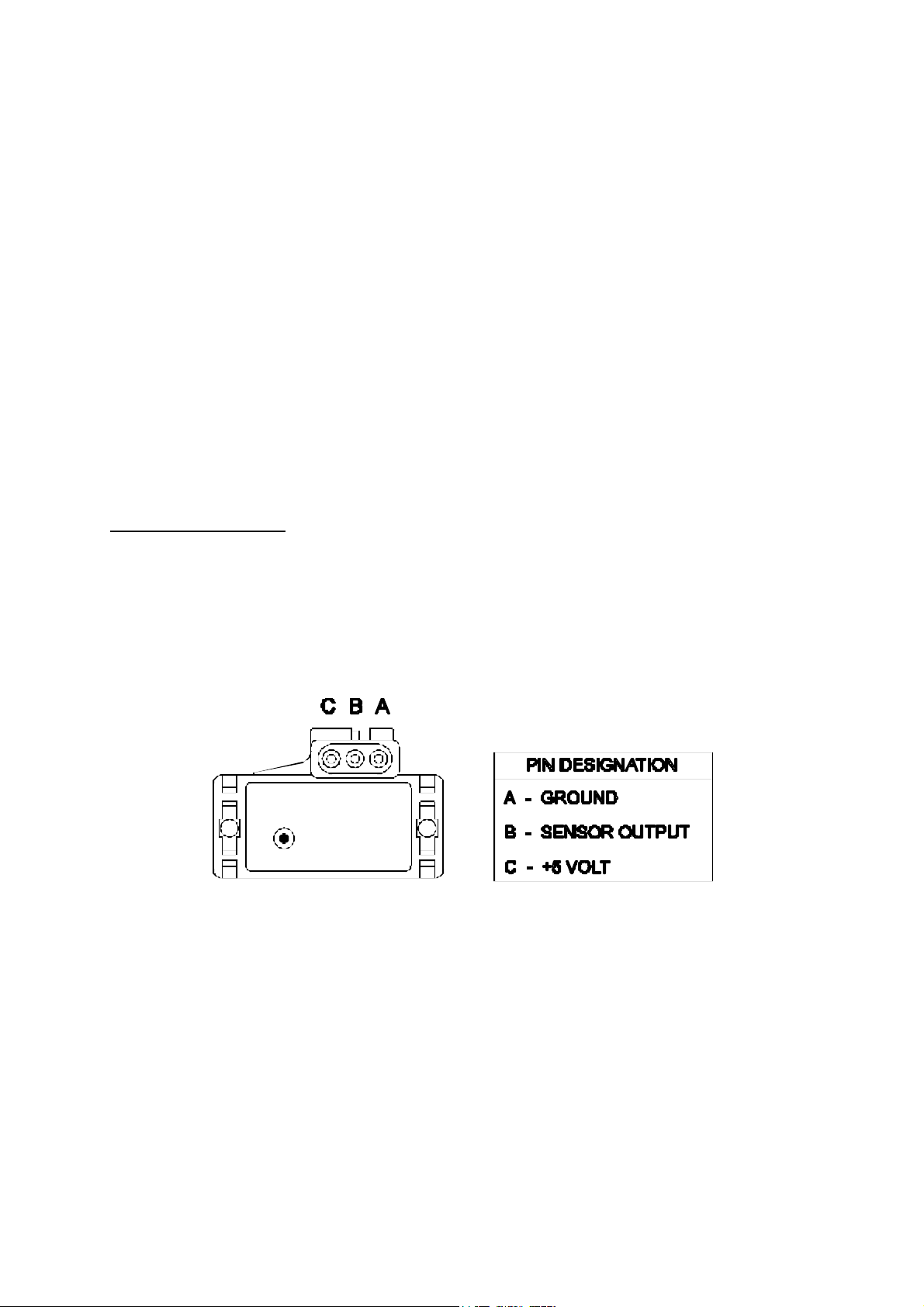
1.3.2. Coolant Temperature Sensor
The coolant temp erature is used to determine t he fuel mixture corrections requir ed when not
at op erating temp erature.
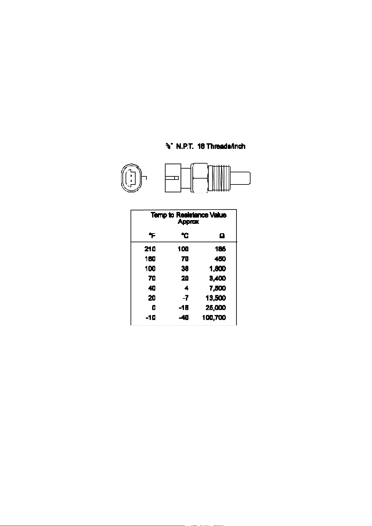
The coolant temp erature sensor has a solid brass t emp erat ure sensing tip . Refer to the diagram
below for technical details of the sensor. The coolant sensor supplied is an industry standard
component and some engines may already have provision for this type of sensor.
The coolant temperature sensor is designed to screw into a threaded hole and protrude into the
engine coolant stream. For air-cooled engines, the sensor can be embedded directly into the
engine block or used to sense oil temperature.
Locate a suitable p osition on the en gine which will allow the hole and t hread t o be machined,
12
Page 18
and which gives access to the coolant stream. The sensor should be mounted after the engine
and before the thermostat in the coolant circuit. Since most engines have existing temperature
sensor holes, it is often p ossible to mount the Haltech sensor in one of these holes. A thread
adapter is sometimes necessary. In some engines only one temperature sensor hole exists and
is used for the dashboard gauge sender. It is usually possible to install a tee-piece to allow
both the dashboard sender and the Haltech sender to share access to t he same t hreaded hole.
If it is necessary t o drain t he coolant from the vehic le t o fit the t emp erature sensor t hen the
factory manual for the engine should be consulted for the correct p rocedure to restore the
coolant and purge the cooling sy stem of air.
13
Page 19
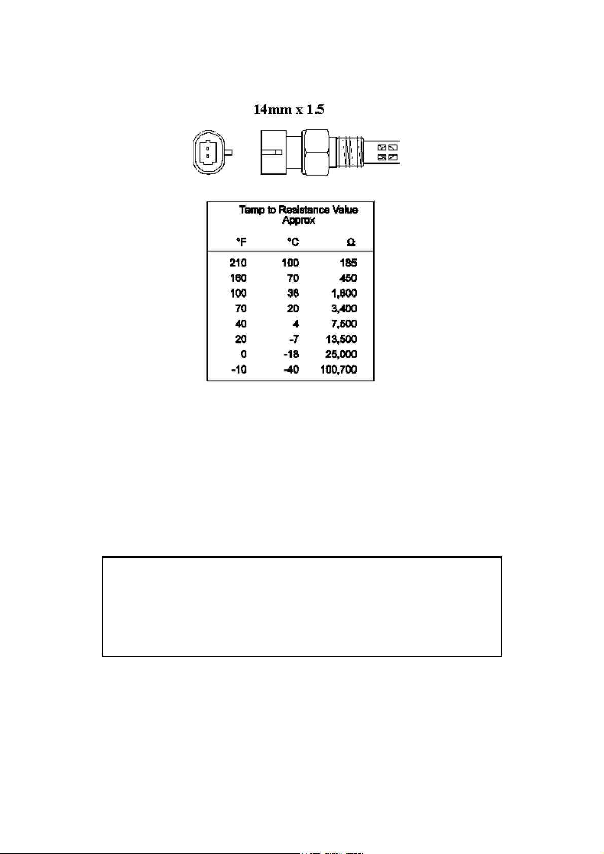
1.3.3. Inlet Air Temperature Sensor
The air t emp erat ure sensor is used to compensate for changes in air density due to air
temperat ure. Cold air is denser than warm air and t herefore requires a great er volume of fuel
to maint ain the same air/fuel ratio. This effect is most not iceable in forced induction engines.
The Haltech F10 will automat ical ly comp ensat e using the signal received from the a ir
temperature sensor.
The sensor should be mounted to provide the best representation of the actual temperature of
the air enterin g the combust ion cha mber, i.e. aft er any turbo or supercharger, and intercooler,
and as close to the head as p ossible. T he sensor needs to be in the moving air stream to give
fast response times and reduce heat-soak effects.
Note: The Haltech air t emp erature sensor will read temperat ures up to 120° C
and temperatures above this will be int erpret ed as a fault condition. The air
temperat ure aft er some turbos and sup erchargers can exceed t his. If this occurs
with your engine you should consider fitting an intercooler to reduce air
temperat ure and increase char ge density . If t his is not possible then the air
temperature sensor should be p laced upstream of t he turbo or supercharger t o
monit or ambient air temp erature.
Once a suitable position has been located for the air temperature sensor a hole should be
drilled and tapped t o accept the sensor. Remove the manifold or inlet tract from the en gine
before machining the sensor mount. Do not allow any metal particles to enter the inlet
manifold of the engine as these will be drawn int o the engine and damage it. Wash all
components before reassembly.
14
Page 20
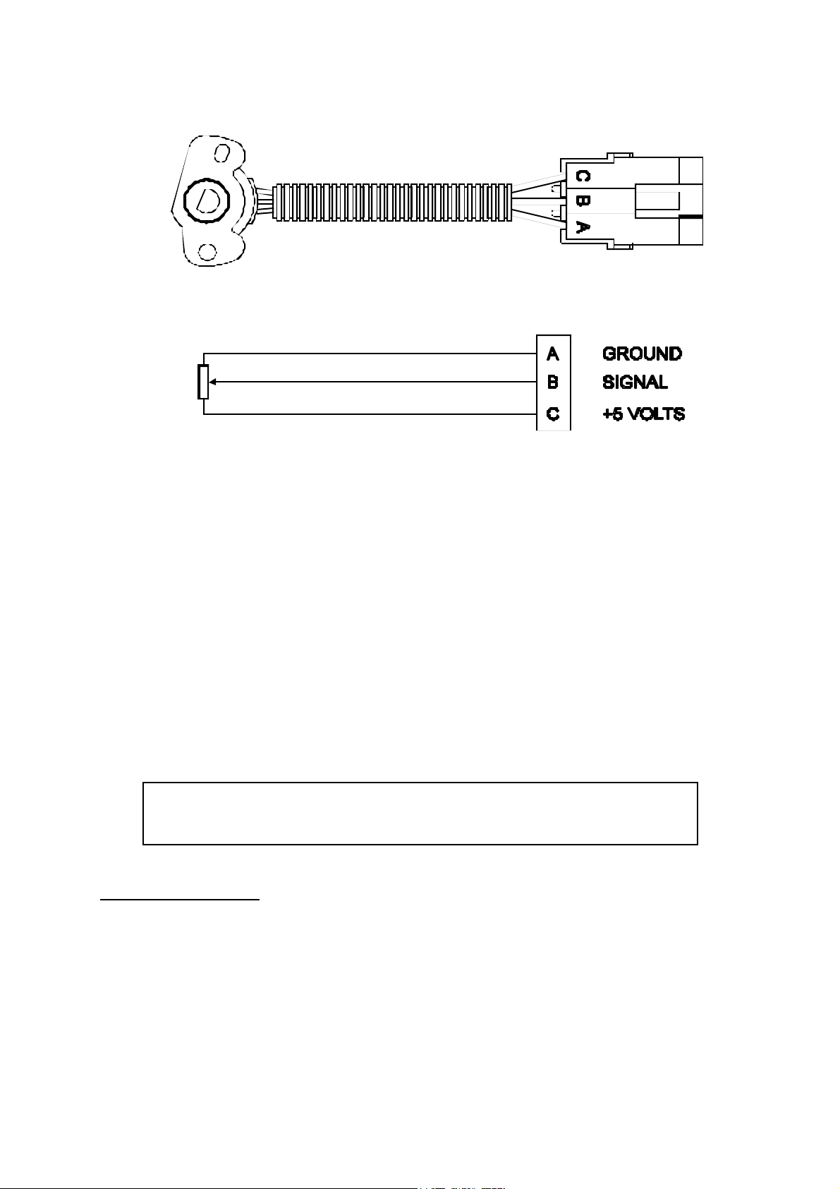
1.3.4. The Throttle Position Sensor (TPS)
The throttle position sensor is mounted to the throttle butterfly shaft to measure its rotation. A
TPS is common on many late model engines and the Haltech sensor should attach with little
or no modification. The throttle shaft must protrude from the side of the throttle body. This
may require the machining of the throttle body or the manufacture of a new throttle shaft. The
inner mechanism of the sensor rotates with the shaft. If the shaft is round then file a flat
surface on the shaft so that it will p ass through the sensor assembly . The TPS should be
mounted against the side of the throttle body, using two screws, such that the throttle shaft
and t he sensor mechanism can rotate freely. The absolute range of sensor movement is not
important as the sensor can be calibr at ed using the programmin g software.
Your engine may have a Throttle position sensor already fitted and it is often possible to make
use of this TPS. The Haltech supplied TPS has a resistance value ranging from 0 to 10kΩ.
The resistance value of t he installed TPS does not have to be the same since the ECU uses a
throttle calibration function to determine the position of the throttle based on the signal
receiv ed from the TPS. Be sure to wire t he TPS so that the ECU sees a closed valu e when the
throttle is closed, the Engine data page field “throttle position” should read “closed” or “0%”
when the t hrott le is closed.
Note: M ake sure that the axis of rotation of the shaft is exactly aligned with the
axis of rotation of the sensor. Also, do not use the TPS as a throttle stop. In
either case, t he TPS will be damaged.
F10A and F10A-8 Only
1.3.5. Mount Optional Exhaust Gas Oxygen Sensor
The optional exhaust gas oxygen sensor must be mounted in the exhaust pipe near the exh aust
header or e xtractors, usually aft er the collector. The sensor uses the exhaust gas to detect if
the engine is lean or rich. M any late model engines already have provision for an exhaust gas
oxygen sensor and the sensor provided should fit any standard exhaust mount. Some exh aust
systems have the sensor mount up to around half a meter (2 feet) down stream from the
exh aust headers.
If the exhaust system does not have an existing sensor mount then a new mount will have to
15
Page 21

be welded to the exh aust system.
When rout ing the elect rical conn ect ions to the exhaust gas oxygen sensor do not allow the
harness to t ouch the exhaust p ip e as t he heat will damage them.
See Chapter 15 [15.3] for more information on exhaust gas oxygen sensors.
1.3.6. Route Wiring Harness and Connect Sensors
Lay the main wiring harness out in the engine bay with the sensors mounted to ascertain the
best fit for the harness. Pass the wiring loom through a hole in the engine bay firewall and
into t he passenger compartment where the ECU will be mounted. Either use an existing hole
or cut a new hole to suit. Use a rubber grommet or similar device to p rotect the harness from
being damaged by rubbing on the sharp edge of the hole.
WARN IN G:
DO NO T ALLOW TH E HARN ESS TO TOUCH HO T EXHAUS T
PARTS INCLUDIN G MAN IFOLDS OR TURBO C HARGERS .
TRY TO RO UT E TH E M AIN H A RN ES S AWAY FRO M HIGH
VOLT AG E IGNIT IO N LEADS . UNDER NO CIRCUMS TANCES RUN
ANY WIRING PARALLEL TO, OR IN CONTACT WITH THE
IGNITION LEADS .
Note: Be neat. Run the harness in a tidy fashion. Try to run the harness along
paths used by original wiring. Use nylon cable ties to secure the harness in
place, but do not stress the wiring or connectors.
Once the harness is fit ted, connect all the sensors to their app ropriat e p lugs.
1.3.7. Power Relays
There are two relays used with the Haltech F10, the Main Power Relay (with a grey wire) and
the Fuel Pump Relay (two orange wires). These relays are identical parts so it is not important
which relay go es in what connector.
16
Page 22
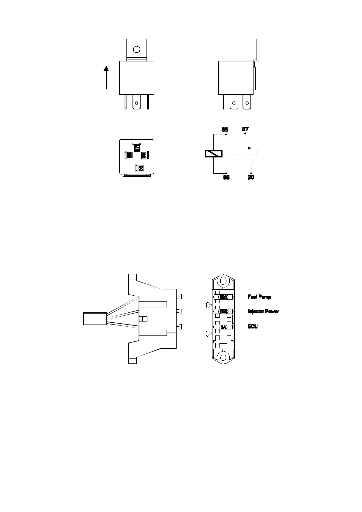
These relays should be mounted on the firewall or an inner guard. Do not mount the relays
such that they could catch and collect splashed water. Residual water inside the relay housing
will cause t hem to fai l. Mount them with the tab upwards as shown in the diagram.
1.3.8. Fuse Block Assembly
The fuse block assembly holds the fuses that protect the various components of the Haltech
F10 system.
The fuse block is supplied from the factory with fuses installed. The fuse ratings are shown in
the diagram and should not be changed as these have been selected for best protection.
Altering the fuse ratings could cause severe damage to the F10 system.
The fuse block should be positioned so that it can be easily accessed in case of fuse f ailure.
Do not mount the fuse block where it could be exposed to water. M ount via the two screws
holes in t he block. Ensure that vibration will not cause t he screws to vibrate loose.
Connect the Fuse Block assembly to the M ain Harness.
17
Page 23

1.3.9. Electronic Control Unit (ECU)
The Haltech F10 is not designed to be waterproof. It is desirable that the ECU be given as
much protection from the environment as possible. It is recommended that the ECU be
mounted inside the passenger compartment, either on the firewall, under the dashboard or
under the passenger seat.
The ECU has four mounting holes that allow it to be mounted to most flat surfaces. In
extreme cases of vibration, the ECU should be mounted on rubber anti-vibration pads. When
mounting the ECU remember that the communications connector on the loom should remain
accessibl e for ease of programmin g.
18
Page 24
1.3.10. Flying Leads
Locate and conn ect the following flying leads.
Black (Ground)
Locate a good chassis ground point and connect the black wire.
Re d
(Battery Supply +12V) Locate a source of continuous +12 volts and connect the red
wire. Connecting direct to the positive battery terminal is suggested.
Grey
(Ignition Switched +12V) The grey wire is used to control the operation of the Haltech
F10 power relay. It needs to be connected so that it sees 12V only when the ignition
switch is on and during cranking. This wire does not draw a large amount of current (<
0.5A). Do not connect to the accessory outputs of the ignit ion swit ch.
Green
(Aux In) The green wire is used as the Aux In channel. This is used if you wish to use
the Aux Inp ut for Torque Converter control, a turbo timer, etc (Refer Chapter 16
PWM Outputs, 72).
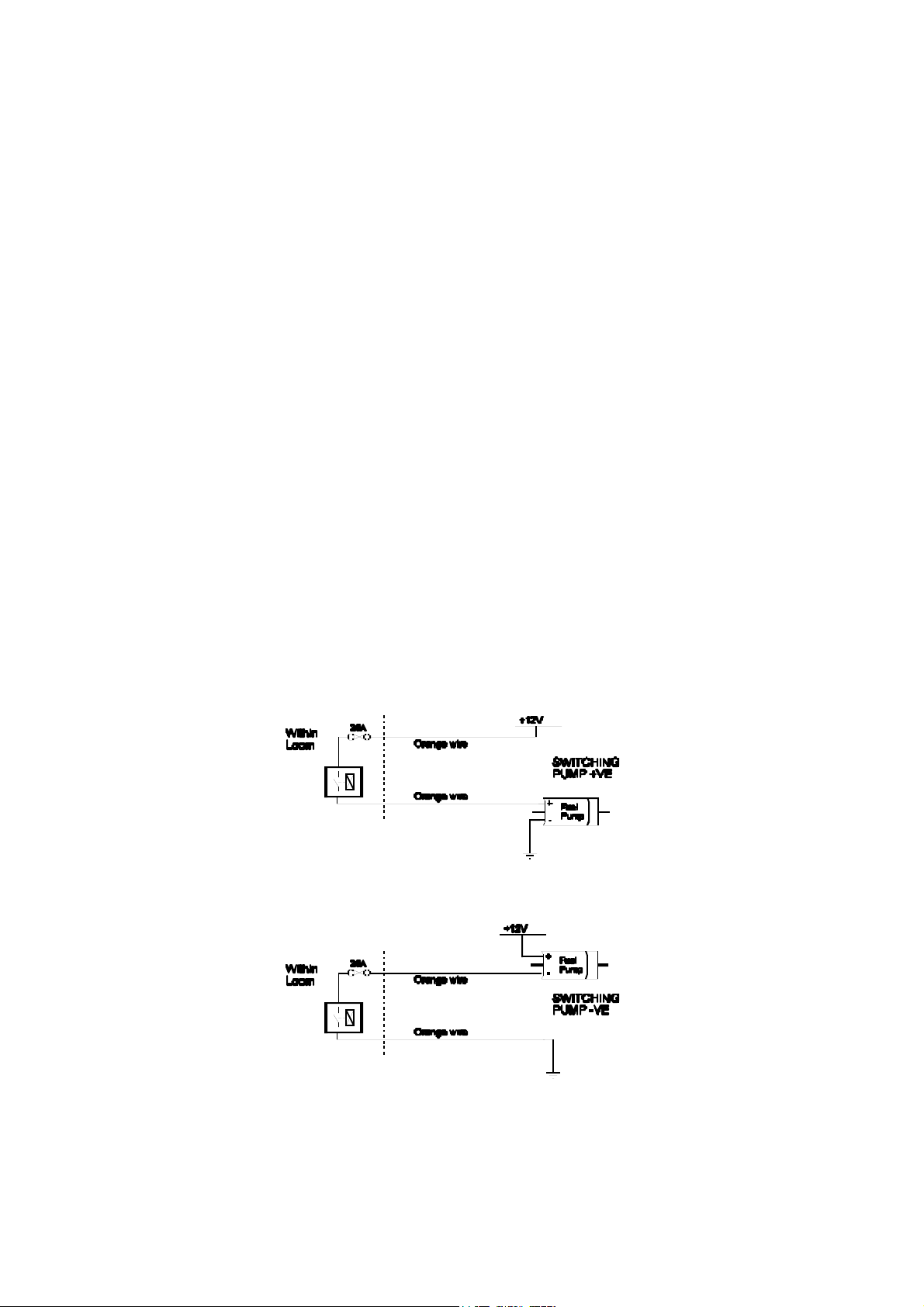
Orange
The two orange wires are used to op erate the fuel p ump. When t he Halt ech F10 ECU
wants t o op erate the fuel p ump it will close t he fuel p ump relay connecting the two
orange wires together. The diagrams show two examples of wiring the fuel p ump. Do
not add extra relays to the fuel pump circuit.
Ex ampl e 1: Connecting to the p ositive si de of the fuel pump.
Ex ampl e 2: Connecting to the n egative side of the fuel pu mp.
Regardless of which e xample is used bot h will operate correctly . Note t hat the orange wires
are connected internally within the loom when the relay is closed. As a result it does not
matter which orange wire is used to connect to the fuel pump.
19
Page 25

F10A and F10A-8 Only
1.3.11. Install and connect Optional Idle Speed Motor
If y ou are not using the Idle Speed Cont rol, tie the loom connector back neatly in t he engine
bay . If t he engine has a suitable Id le Sp eed Motor then you may connect it to the wiring loo m,
otherwise y ou can inst all a Haltech supp lied idle air cont rol mot or. For details on how t o
install and plumb the Idle Sp eed Motor, see Chapter 14.
F10A and F10A-8 Only
1.3.12. Install and connect any Optional Outputs
If you are planning to use any of the Programmable Op tional Outputs, install and connect
them now. Dep ending on what opt ions y ou are using, the wirin g will b e different .
(Refer SECTION 4 F10 Inputs & Outputs, 61)
1.3.13 Connect the Trigger Sensor
The F10 requires a trigger signal on each spark event in the engine rotation ie. A 4-stroke V8
will have 4 sp ark events per engine rot at ion (or 8 sp ark events p er cam rot ation). The trigger
signal can be one of the following:
Coil Negative:
The F10 can use the switching voltage at the negative terminal of the ignition coil as a
trigger signal in what is called a “coil negative” trigger set-up. To wire the F10 for
this trigger set-up; connect the trigger wire in the Haltech loom to the negative
terminal of the ignition coil.
Tacho Output:
Some popular ignition systems have a tacho output signal which can be used to trigger
the F10. It is necessary to use this output if the ignition system used is a Capacitive
Discharge Ignition system with a multiple spark function.
Hall Effect and Optical Triggers:
The F10 can also accept a signal from Hall Effect and Op tical triggers sy stems. T hese
trigger dev ices genera lly 3 have connections each - ground, p ower and the signal. The
trigger connector on the Main Harness has six pins. These pins and their connections
are shown in the diagram below.
20
Page 26

PIN FUNCTION
A GROUND
B MAIN TRIGGER
C N/A
D N/A
E N/A
F 13.8 V DC
For more information on the F10 trigger system; (Refer Appendix D Trigger Interface,
92).
1.3.14 Connect the ECU
The ECU can now be connected and tested. Be sure to engage the clip on the main connector,
this will mak e sure the main connector p art s mate correctly and redu ces the m echanical strain
on the connector bodies. The system can now be tested as described in the following chapters.
21
Page 27

CHAPTER 2 GETTING ONLINE
Now that your Haltech F10 is installed with all the sensors in place the system can be
connected to t he programm in g comp uter. T his will allow the readings from all the sensors to
be displayed on the screen and checked for correct operation.
To connect the PC to t he Halt ech F10 ECU you will need the p rogrammin g cable and
programmin g disk supplied.
2.1 Connecting the Haltech F10 to a Computer
The p rogramming cable supplied with t he Halt ech F10 is a standard seria l link extension
cable. One end of the cable will plug into t he Main Harness PC Interface connector (near the
main connector). The other end should plug into the mating connector at the back of y our
computer. The plug on the computer may be marked "Serial", "Mouse" or "COM". Almost all
laptops will have this plug. If t here is no 9 pin plug which it will connect to, check to see if
there is a 25 p in D-type p lug av ail able (some desk top computers will have this). If this is t he
case, an ap p ropriate cable can be supp lied on request . Alt ernatively , most electronic retailers
will have a 25-p in to 9-pin converter.
Any time you wish to communicate with the F10 ECU it needs to be supplied with power.
This usually involves just turning on the ignition switch. If at any stage power is not on, or the
programmin g cab le is disconnected while attempting to communicate, the programming
software will display t he message RECONNECT HALTECH. To rectify this, reconnect
power and/or the p rogramming cable.
2.2 Ope rating the Software
2.2.1 Computer Requirements
The comp uter required to program the Haltech F10 can be any IBM-PC compatible p ersonal
computer from the XT onwards (i.e. the AT, 386, 486 or Pentium computers). The
requirements are fairly modest. The computer must have at least 640K of RAM (with about
590kb free for executable programs), one 3.5" disk drive and a CGA, EGA, or VGA screen.
(Virtually all reasonably modern laptops running MS-DOS (version 5.00 or higher) will fit
this description).
2.2.2 Installing the Software
The Programming Disk supplied with the Haltech F10 has an installation program that allows
you to install the software onto the PC’s Hard Disk. M ost modern PCs have a hard disk. If
your PC does not have a hard disk, the F10 Program can run directly from the disk supplied.
Installing the soft ware on the Hard Disk will sp eed up t he program and avoid hav in g to fiddl e
around with floppy disks. The installation program need only be run once.
22
Page 28

If you do not have a Hard Disk, go to the section titled Running the Software from the
Fl oppy Dri ve .
To install the software follow these steps.
Boot up Computer
Turn your PCs power on and boot up M S-DOS as instructed by the computers Users Manual.
If a shell program or menu utility runs automatically when you boot y our computer, exit it
now. You should see something like this:
C:\>_
This is the ‘DOS Prompt’. It is DOS’ way of indicating that it is waiting for a command. The
C: indicates that the C drive is the drive currently selected. If you do not have a hard disk,
your p romp t will p robably look like this :
A:\>_
Select the Drive
To run the INSTALL program, you must insert the supplied disk in the disk drive. If the drive
is t he A drive, then it must be currently selected. T o select the A drive (or B drive if it is the
required drive) type :
The yyyy key is the Enter Key. On some keyboards it may be called the Return key. You should
now see the prompt :
A:\>_ or B:\>_
Run the INSTALL Program
To run the Install program type :
The Install program will now run. Follow the instructions given. The program will suggest
that the software will be placed in t he HALTECH direct ory . You can change t he dest ination
directory, but it is not recommended that you do unless you understand how directories work.
When it is finished, t he installation p rogram will t ell y ou if the installation is successful. If it
was not, consult the trouble shooting section of this manual.
The F10 Program is now ready to run.
Dy or %y
LQVWDOOy
23
Page 29

2.2.3 Running the Software from the Hard Disk
Boot your computer up as described earlier. If your computer is already on, make sure the C
drive is currently selected. To change to the HALTECH directory type :
or, if you used a different destination directory, type that path.
To start the program type :
)y
The F10 p rogram will now run. The next section is on running the software from a floppy
drive. You can skip this section and go straight to the section entitled Azerty Keyboards.
F'?KDOWHFKy
2.2.4 Running the Software from the Floppy Disk
To run the software from a floppy drive, boot your computer up as described earlier. Insert the
Programming disk in the disk drive. If t he driv e is t he A drive, then it must be currently
selected. To select the A drive (or B drive if it is the required drive) type :
You should now see the prompt :
A:\>_ or B:\>_
To start the F10 program typ e :
Dy or %y
The F10 program will now run.
)y
2.2.5 Azerty Keyboards
M ost countries use a keyboard where t he first six letter key s across the top row are :
This is called a Qwerty keyboard. Some countries use an alternative, which is called an
Azerty keyboard, where the Q and W keys are swapped with the A and Z keys respectively. If
you have an Azerty keyboard, y ou need to run the software slightly differently. When you
would normally type:
TZHUW\
)y
24
Page 30

to run the programmin g software (not the installation software), you need to instead type :
The /A tells t he program y ou have an Azerty key board. The program will adjust accordin gly.
)Dy
2.3 The ONLINE and OFFLIN E Modes
On the F10 system title page, the software asks whether t o op erate in ONLINE or OFFLINE
mode. The OFFLINE mode is very useful to familiarise yourself with the Haltech software,
but cannot be used to make lasting adjustments to the fuel maps except by modifying maps
then saving those maps and re-loading them to the ECU in the on-line mode. Also lasting
changes to the main, fuel and M ain Set-up p ages cannot be made in the OFFLINE mode. Do
not att empt to make lasting changes to the ECU unless there is a special reason for doing so.
If you wish to exp eriment and familiarise yourself with the software press N for OFFLINE
mode, but if the ECU is installed and power is available then we suggest the ONLINE mode
be selected. Press Y to select ONLINE mode.
2.4 Using the System ONLINE
In the ONLINE mode there is a two-way flow of information between the ECU and the
programmin g computer. The communication cable must be installed and power must be
available t o the ECU before the sy stem can communicate. T he ONLINE mode will be used
most frequently. While using the system ONLINE, you can view engine information directly
and make adjustments. Any changes or modifications made on the computer are instantaneous
and will be imm ediately recorded in the ECU. When the p rogrammin g cable is remov ed and
the ignition switched off, the ECU will retain all of its memory. The maps do not need to be
saved, but keeping a copy on disk is always good practice and is recommended. (See 9.1)
Note: If p ower is removed or the communication cable is disconnected or
interfered with, the following message will be displayed on the computer
screen.
RECONNECT HALTECH
If this message app ears check all connections and ensure that the communications cable is not
being interfered with. Also be sure that the Haltech F10 unit is receiving power. (i.e.. ignition
switch is turned "on".)
2.5 The Main Menu
When y ou select ONLINE or OFFLINE mode the Halt ech M AIN M ENU bar app ears. T his
menu bar allows access to submenus giving access to maps, file storage/retrieval, engine data
and options.
25
Page 31

2.6 How to Quit
Throughout the p rogram you can exit from any application by using the menu bars or hot
tT
keys. Pressing
while holding down the
tT
tTtT
in any page will p rompt you to exit the p rogram (i.e.. p ressing
key). If you wish to exit, p ress
tttt
at the p rompt.
<<<<
TTTT
2.7 Checking the Engine Data
The engine data option can only be used when the system is ONLINE. This function allows
all of the engine data variables to be displayed on the screen
This is a very useful function for analysing the engine sensors. To bring up the engine data
tH
press
pressing
Do not attempt to start the engine if the Engine Main Set-up page has not been completed.
Before continuin g check to see if all the sensors are operat in g corr ectly by viewing the engine
data page.
tH
tHtH
from any application. Otherwise it can be accessed throu gh the menu bar by
s2
s2
s2s2
and then
for Engine Data.
((((
26
Page 32

CHAPTER 3 ECU SETUP
3.1 ECU Setup
The F10 ECU can be used to control fuel delivery to many different types of engines and
requires specific information about the engine that it is to control. The F10 software has a
series of set-up pages that allow t he user to p rogram the F10 with these settings, these are:
Main-Setup
Fuel Setup
3.1.1 Navigating the Set-up pages
The F10 Set-up p ages are made up of a series of f ields t hat define the charact erist ics of the
engine that the F10 is to control. These fields can be navigated as follows:
and
Use the Up and Down arrow keys (
Selection typ e, or Text type. The Selection typ e fields give you a number of valid entries for
that field. For example, the valid number of cylinders can be set to 1, 2, 3, 4, 5, 6, 8, 10 or 12.
oooo
) to move between fields. The fields are either
pppp
The Tab and Enter keys (
of t he Tab key will disp lay t he next selection. The Shift and Tab keys together will step
backwards through the selections. Once the desired selection is displayed, the Enter key is
pressed to program that selection. Text Fields require you to enter either text or numbers.
Once the field is selected, the new text can be typed in, with the Enter key to finish. An
example is the Rev Limit. This field can be set between 2000 and 16000 rpm. If you want the
rev limit to occur at 7000rpm, then you would need to select this field using
typ e y
y
yy
.
vvvv
and
) keys are used to change this type of field. Each st roke
yyyy
or
oooo
and then
pppp
3.1.2 Main Set-up
To access t he M ain Setup page press Alt – S to open the Set-up menu then scroll t o the M ain
Set-up menu item and press enter.
Cylinders
The number of engine cylinders needs to be entered here. This parameter is used to
determine the en gine speed.
The valid values for this parameter are: 1,2,3,4,5,6,8,10,12 and 16
Load S ensing
The F10 can use either the manifold pressure or the throttle p osit ion as a means of
determining the engine load. M ost engines op erate using man ifold p ressure to sense
engine load. If your engine employs any form of supercharging, y ou must run in
manifold p ressure mode. Only wild cams, motorbikes or heavily port ed rotaries
require throttle mode - i.e. engines whose vacuum signal is small, or fluctuates greatly.
If you are unsure what to use, contact your Haltech dealer.
The valid values for this parameter are: Throttle and M anifold
27
Page 33

MAP Sensor
The F10 needs to know the type of Manifold Absolute Pressure (M AP) sensor being
used. Enter the correct description here to match. If using throttle p osition mode, set
this parameter to a 1 Bar sensor.
The valid values for this parameter are: 1 BAR, 2 BAR and 3 BAR
RPM Limit
The F10 can limit the maximum rpm at which t he engine will operate. Above this
level the F10 comp let ely cuts fuel or ignition (see be low) to the engine. When the
engine speed drops below the RPM Limit the F10 will resume normal fuel or ignition
delivery. This is known as hard limiting. If the RPM Limit is not needed then set t his
value abov e t he highest operating point of the engin e.
The valid values for this parameter are: 2,000rpm – 16,000rpm
Units
The Haltech F10 programming software can display parameters in either Metric or US
units.
The valid valu es for this paramet er are: M etric, US
RPM Mode
The F10 fuel and ignition maps may be arranged either in 500 rpm increments to
10,500 rpm, or in 1000 rpm increments to 16,000 rpm. Changing settings alters the
way the ECU reads t he M aps, and will chan ge the t uning of the en gine dram atically .
Do not change this setting once tuned unless necessary.
The valid values for this parameter are: 10,500rpm – 16,000rpm
Road S peed Value
This paramet er is a multip lier t hat allows the user to calibrat e t he road-speed input by
comp aring the road-speed value on t he Engine Dat a Page with that of the vehicles
sp eedometer. To calibrate the road-sp eed inp ut, modify this value until the road-sp eed
value on the engine data page matched that on the vehicle speedometer.
The valid values for this parameter are: 100 – 60,000
F10 Type
This field is only accessible by Haltech but serves as an indication of which of the 4
F10 variants is connected.
The valid values for this parameter are: F10, F10A, F10-8, and F10A-8
3.1.2 Fuel Setup
To access t he Fuel Setup page press Alt – S to open the Set-up menu then scroll t o the Fuel
Set-up menu item and press enter.
Ign / By
Ignition Divide By is the number of ignition p ulses t hat will be counted until the next
injection pulse (remember the trigger wire for the F10 should ideally have one trigger
event for each sp ark event). For almost all mult ip oint sy stems, injection should occur
once per revolution and so Ignition Divide By should be set to half the number of
cylinders. If the sy stem is operating in Batch Fire mode, or is a rotary, then a value of
1 is suggested.
28
Page 34

The valid values for this parameter are: 1, 2, 3, 4, 5 and 6
Decel Cut-Off
A common fuel saving feature in original equipment computers is a fuel cut-off on
decelerat ion. This will cut fuel delivery to the engine while coasting down hills with a
closed throttle. This feature can be enabled or disabled on the F10. It is better, when
first tuning, to disable this function.
The valid valu es for this paramet er are: Enab le and Disable
Inje ction Mode
Depending on the ECU settings the F10 splits its four (F10 and F10A) or eight (F10-8
and F10A-8) injector driver outp uts into two banks (see chapter 13, 13.1). INJ1 and
INJ2 comprise the first bank. INJ3 and INJ4 form Bank 2. The fuel can be injected in
three different modes.
Multipoint injection f ires all the inj ectors t ogether. This is t he most common set-up
and will normally be used on engines with mult ip oint injection manifo lds (one in ject or
per cylinder).
Batch-fire injection is usually used in throttle body or non-turbo rotary set-ups and
fires the two banks of injectors alternately. On eight and twelve injector fuel rails, with
high-f low injectors, t his may also help reduce fuel pressure oscillations caused by all
injectors p ulsing together.
Staged injection is usually used on high boost turbo engines. Injector Bank 1 fires all
the time, just as in a multip oint set-up. Beyond a set boost pressure, the second bank
of injectors is enabled. These "staged" inje ctors are normally upstream of the primary
injectors, addin g to t heir fuel flow. The p oint at which the F10 switches in the
secondary injectors is set via the Staging Bar Number field. Staging permits high fuelflow cap ability, but maintains accuracy and cont rollability at light load and idl e.
(Refer C.3 Injector Staging, 90).
WHEN FINISHED SETTING THE INJECTION MODE, SEE
(INPUT/OUTPUT PAGE) TO S ET THE INJ 1 - 4 DRIVERS TO THE
THIS IS IMPORTANT AS THE ECU WILL NOT OPERATE
CORRECTLY IF THE INJ 1-4 DRIVERS HAVE NOT BEEN
CONFIGURED P ROP ERLY. AT WORS T, SO ME INJ ECTORS MAY
NOT FIRE OR THE INJECTOR DRIVERS MAY DESTRUCT AFTER
THE F10 AND F10A ARE NOT CAPABLE OF DRIVING 8 LOW
IMPEDANCE INJECTORS. THES E ECU DO NOT HAVE THE
WARN IN G:
CHAPTER 13.1
CORRECT STATE: ENABLED OR DISABLED:
A PERIOD O F TIM E.
F10 AND F10A ONLY
EXTRA INJECTOR DRIVERS MENTIONED ABOVE.
29
Page 35

Post Start Temp Limit
This field sets the temp erature at which the post start correction map is either enabled
or disabled. The following field “Above/Below” allows the user to enable the Post
map above or below the temperature set in Post Start Temp limit (this is p art icularly
useful for engine, which when hot require extra fuel due to vapour lock. From when
the mot or is st arted to when t he engine temperature reaches the Post Start Temp limit,
the Post Start correction map will app ly correction to the injection times.
The valid values for this parameter are: 0°C – 127°C (Above and Below)
Post Start Time Limit
This field sets the time for which the post start correction map adds corrections to the
fuel from t he post start map. Post Start is the p eriod of time from when the motor is
st arted to t he Post Start Time limit.
The valid values for this parameter are: 1s – 120s
Staging Bar Number
This field sets t he point at which the staged injectors are en abled (Ref er C.3 Injector
Staging, 90). If t he injection mode is not "Staged Injection" then t his field will not
affect injection.
The valid values for this parameter are: 1-16
Ze ro Throttl e Map
This feature allows t he user to enable or disable a sp ecia l fuel map t hat is used only
when the throttle is closed. This feature should be used for engines that produce
constant vacuum while cruising but irregular vacuum when idling. Typ ical engine
configurations that fall into this category are multiple throttle body set-ups and wild
cams. The zero throttle M ap can allow a very quick and simp le adjustment of the idle
fuel settings. This option can be disabled if not required.
The valid valu es for this paramet er are: Enab le and Disable
Throttle Pump Deadband
This field defines the p ercentage change in throt t le p osition t hat must occur before the
throttle pump is act ivated. This fe at ure allows for “ jit t er” in the throttle that would
otherwise over-fuel the engine.
The valid values for this parameter are: 1% - 20%
Ful l Throttle Map
This feature allows t he user to enable or disable a sp ecia l fuel map t hat is used only
when the throttle is wide open on normally aspirated engines. With some manifold and
or t hrott le designs, p ressures in the manifold can reach close to atmospheric pressure
before full throttle is applied. This effect can make tuning difficult around full throttle.
This map allows the full load settings to be easily set without interfering with lighter
load settings. The throttle position above which this M ap is used is set by the Full
Throttle Threshold field.
The valid valu es for this paramet er are: Enab le and Disable
Ful l Throttle Threshold
See the Full Throttle Map field above for information on this field.
The valid values for this parameter are: 70% - 100%
30
Page 36

Barometric Lock
If y ou wish to lock the baromet ric value t hat is stored by the ECU t o a set value and
override the start-up barometric correction, enable this option. Normally, unless y ou
are using throttle position as a load reference or have another good reason to do so,
leave this option Disabled. Configuring barometric compensation successfully
requires an in depth knowledge of your engine and the environment in which it will b e
op erating. (Refer 8.5 Barometric Correction, 48)
The valid valu es for this paramet er are: Enab le and Disable
Barometric Pressure Lock at xxxx (mBars)
This field allows the user to set the barometric pressure value to which the ECU
corrections will be locked. T he default is 1013mBars ( = 1 Atmosphere @ sea level).
Again, unless y ou have sufficient knowledge about your engine characteristics and the
environment it is operat ing in, leave this field as it is. (Refer 8.5 Barometric
Correction, 48)
The valid values for this parameter are: 523mbar – 1046mbar
Disable Injector Outputs
Allows y ou turn off all inject or outp uts. Setting the value t o YES will cut all injector
output which allows an easy way to check the trigger when cranking without having to
locate the injector fuse and remove it. Normally this field should be set to NO to allow
the inject ors to fire.
The valid values for this parameter are: Yes and No
Over-boost Fuel Cut
This field enables or disab les a f eat ure which will cause the fuel to be cut when the
manifold p ressure exceeds a set p ressure. If this field is enabled t he followin g fields
become visible:
Over Boost Limit
This is manifold pressure at which t he fuel is cut .
Over Boost Restore
This is the manifold pressure at which the fuel supply is restored.
The “Over Boost Limit” must exceed t he “Over Boost Rest ore” pressure by 12 kPa
(2.3psi) to eliminat e boost spikes.
3.1.3 Trigger Set-up
To access t he Trigger Set-up p age press Alt – S to op en the Set-up menu then scroll t o the
Trigger Set-up menu item and press enter.
The following Trigger Set-up p age descrip tion out lines t he basic operat ion of each ind ividua l
field, the table below give app lication information.
Switch 1 – Pull-Up 1
This switch adds a 6.2kΩ pull to +5V at the input to the trigger circuit.
Switch 2 – Pull-Up 2
This switch adds a 2.2kΩ pull to +5V at the input to the trigger circuit after a series
inp ut impedance.
31
Page 37

Switch 3 – Pull to Ground
This switch adds a 4.7kΩ pull to ground opp osing the Pull-Up 2 resistor.
Switch 4 – Filter Capacitor 1
This switch adds a 0.1uF filter capacitor to the inp ut of the trigger circuit.
Switch 5 – Filter Capacitor 2
This switch adds a 0.001uF filter capacitor to the inp ut of the trigger circuit after series
impedance.
Switch 6 – Resistor Bypass
This switch applies a short circuit across a 4.7kΩ series resistance on the inp ut of the
trigger circuit.
S wi tch 7 – Inpu t Impedance
This switch allows the user t o set t he inp ut protect ion imp edance to either low ore
high. High is used in coil negative applications where low is used for Hall Effect or
optical digital trigger applications.
Switch 8 – Input Threshold
This switch controls the threshold volt age at which the trigger cir cuit will switch state.
Typical Applications
Sof tware Switches
Trigger Type 1 2 3 4 5 6 7 8
Haltech S1/S3,S2/S4 Hall
Effect Sensor
Ignition Coil Negative
terminal
Driven 12V square wav e
(some tacho output
signals)
2222 3333 2222 2222 3333 3333
2222 2222 3333 3333 3333 3333
2222 2222 3333 3333 3333 3333
LOW 3.4V
HIGH 3.4V
HIGH 3.4V
3333= O n 2222 = Off
32
Page 38

CHAPTER 4 ADJUSTING HALTECH MAPS
This Chapter describes the fuel map s that are the heart of the F10s ability to accurately
deliver fuel to the engine.
The following instructions assume that the user has the software running ONLINE on a PC,
with the ECU powered and connected via the supp lied programming cable. It is also
assumed that the user is familiar wit h the ECU Set-up described p reviously.
4.1 What are maps?
The inject ion times data required t o fuel t he engine prop erly at different engin e load sp eed
temperature etc.. are stored in the F10 ECU of numbers called a look-up table. The F10
determines t he engine's load and sp eed, and uses t hese t wo p arameters as an inde x to the
table. This table is called the Fuel M ap. For instance, at an engine sp eed of 4000 rpm and at
-20kPa, the relevant number in the table may be 4.35. If the engine app roximates -20kPa at
4000 rpm, then the computer will extract the value of 4.35ms from the table as the base
injection time. This value is then adjusted to compensate for numerous conditions, such as
temperat ure or acceleration, and then the ECU holds the injectors open for that time on the
next injection.
It is possible to p rogram the F10 by directly chan gin g the valu e of e ach nu mber by
programmin g in the numerical mode (Refer 4.5.6 Numeric Mode, 37), but this can be
extrem ely difficult, so t he Halt ech allows y ou to change the numbers by manip ulating
graphics in maps p resented as bar graphs. (This is much simpler and allows you to visualise
the map)
Since it is diff icult to interp ret all the t able's values at once, the p rogramming software
divides t he map by engine sp eed into a series of rpm ran ges
point is represent ed by a vertical bar. When y ou view a ran ge from the Fue l M ap , you see a
bar chart of injection time versus load for all the load points in the table at that speed.
There are other tables in the F10, such as those used for temperature corrections. They are
indexed by only one parameter, and so are not divided into ranges. These tables are also
called maps.
. Within the r an ge, each load
4.2 What is mapping the Engine?
Mapping the engine is filling the look-up tables with the correct values for your engine. This
is done by adjusting the heights of the bars within the maps. Bars may be adjusted one at a
time, or in group s. The Haltech p rogramming soft ware has been designed to make en gine
mapp ing as simp le and intuitive as p ossible.
4.3 Using the Software
In order to make the software easy to use, the program presents y ou with a menus bar at the
top of the display . The menu bar is accessed through simple combinations of key strokes.
Once the ap p ropriate menu has been accessed a sub-m enu ap p ears giv in g cho ices on
33
Page 39

available p age heading. To incr ease efficiency there are also a nu mber of hot-keys that allow
you movement between pages without accessing the menu bar.
4.4 Accessing the fuel maps
To access all t he fuel and comp ensation map s press sP
From the M aps Menu select the appropriate map using the cursor keys to scroll up or down
the list and when t he desired map title is highli ghted p ress Ent er. (Some map s such as the
base fuel map have sub-menus for the different ranges if the maps.)
sP
To view the base Fuel M ap s specifica lly , press
and press
Fuel map, each ran ge can b e accessed by p ressing the
next, previous range and jump to a p articular range. See below for an example map:
then select the desired range from the sub-menu and press
y
y
yy
sP
sPsP
sP
sPsP
then select “fuel map” from the menu
1111,3
, this opens the Maps M enu.
. While in the
yyyy
3
33
and
keys to move to the
----
OOfffflliinnee MMooddee:: FFuueell mmaapp:: 22550000rrppmm ((RRaannggee 66)),, HHiigghhlliigghhtteedd BBaarr -- BBaarr 1166 aanndd HHeeiigghhtt –– 44..009966 –– aass ddeessiiggnnaatteedd
uuppppeerr lleefftt ccoorrnnee rr
OOnnlliinnee MMooddee:: FFuueell mmaapp:: 22550000rrppmm ((RRaannggee 66)),, HHiigghhlliigghhtteedd BBaarr -- BBaarr 1166 aanndd HHiigghhtt –– 44..009966 –– aass ddeessiiggnnaatteedd uuppppeerr
lleefftt ccoorrnneerr
34
Page 40

4.5 Navigating the Map
For all maps whether single or multi ranged navigating the map is done in the same way
(with multi-ranged maps the same navigation between ranges is the same as choosing
another map.) Once a map is displayed on the screen by following the instructions above
the bar heights can be adjusted to adjust the fuel delivered.
The height of the Bars is adjusted by using the up and down arrows keys, the PgUp and
PgDn keys (
or decreasing the height of the bars increases or decreases the amount of fuel contributed to
the total fuel by that bar of t he displayed map . (See the command summary at the end of
this section for a full list of key functions Refer 4.7 Command Summary for Maps, 40).
The active bar (the bar that is affected by the up and down cursors) is highlighted on the
comp uter screen to distinguish it from t he remainin g bars in the map . To change the active
bar, use the left and right arrow keys (r
saving fun ctions programmed to make mapp ing the engine simpler.
) or a combination of these keys with the Shift and Ctrl keys. Increasing
r qqqq). The Haltech software ahs a number of time
rr
Note: When two keys are displayed together, such as sU
the second key must be pressed while the first key is held down. In this case,
the
key would be held down while the
ssss
sU
sUsU
key is p ressed.
UUUU
, this means that
4.5.1 Current Location
Pressing
that is currently being used. This bar is easily identified by an arrow directly above it
pointing down. As the engine sp eed and load ch an ges, the arrow moves with it . The Home
key is useful for finding the engine's operation point very quickly.
will t ake you to the range at which t he engine is running, and highlight the bar
4.5.2 All Ranges
Across t he ranges, the curv e of the fuel m ap does not chan ge gre at ly . Usually the shap e
remains much the same, and the height chan ges accord in g to the volumetric efficiency of the
engine. In order for all the fuel ranges to initially be set up quickly, the Haltech F10 system
sU
allows y ou to program a ll rpm r an ges simu ltaneously with the same data.
Ranges on, and the words All Ranges appears under the title.
When t he All Ranges function is active, a bar adjusted on one graph is copied to the same bar
on all the ranges. If you use this option, you can set the shape of the map at any range, and all
other ranges will be identical at every bar you adjusted. This feature enables all grap hs t o be
given an initial shape that should run the engine, albeit rather roughly. Once you have used
sU
the All Ranges option for a starting point, press
opt ion and tailor each map individua lly .
This option is only available on the Base Fuel and Ignition Maps.
sU
sUsU
once more to exit the All Ranges
sU
sUsU
turns All
4.5.3 Selecting Groups of Bars
35
Page 41

Groups of adjacent bars may be highlighted and adjusted together.
t
t while using the left or right arrow keys, rrrr qqqq, and you will highl i ght a group of
Hold
tt
bars. This group will now act in unison when increasing or decreasing the height of the Bars.
To de-select t he highlighted Bars use the
s
s and arrow keys together.
ss
4.5.4 Percentage Changes
Pressing Alt -P will p rompt y ou to enter a p ercentage chan ge to the select ed bars. An entry of
"20" will incr ease e ach bar by 20%, while an entry of "-15" will decrease the bars by 15%.
This change only affects the highlighted bar(s).
4.5.5 Linearise
When a group of bars is selected (more than two), this function can be used to set the values
between the end points. Highlight the bars between two load points that are known to be
sO
correct and p ress
between the t wo end p oints t o form a straight line. This feature facilitates fast programmin g
and the smoothing of maps.
sO. The p rogramming software will aut omatically adjust all the bars
sOsO
36
Page 42

4.5.6 Numeric Mode
Pressing Alt -N will take y ou into numerical mode, displaying the map as a spreadsheet . This
mode is available if required, but graphical mapping is normally exercised as it is much easier
to use. Numeric mode al lows you to ent er the precise inject ion valu es across all t he rev and
load ranges as seen in the diagram below:
In numerical mode only a fraction of the entire map is shown on the screen but the whole
display can be accessed. To navigate the map use the cursor keys to move the highlighted
cell, to change t he value of a cell, hi ghlight that cell, typ e the value required and then press
the enter/return key. The values in the table must be a multiple of 0.016ms, if a different
value is ent ered the p rogram will round to the nearest valid value.
key.
To exit from Numeric M ode and go back to using the maps press the
}}}}
4.5.7 Bar Increments
The Up and Down arrows,
determined amount, usually the smallest possible increment. PgUp and PgDn change the bars
also by a pre-determined amount. These increments (the value of the keystroke) can be
changed by the user. sL
be changed.
Normally, the bars are altered by adding or subtracting a fixed amount. The adjustment keys
may instead apply a percentage change on each k eystroke.
Screen will switch t o percent age increm ents, tI
sO
sO will sp ace out increment s evenly between the Up /Down Arrows field and the Ctrl
sOsO
PgUp /PgDn field. The result of this op eration will be disp layed once the field is refr eshed,
this can be done by highlighting the field.
sL will br in g y ou to a screen where the increments themselves c an
sLsL
pppp oooo, normally change the bar height in the maps by a pre-
sS
sS on the Bar Increment
sSsS
tI will return y ou to fixed increments.
tItI
37
Page 43

4.6 Duty Cycles
Fuel is delivered to the engine by firing the injectors in sync with the engine, allowing fuel to
flow during the period that the injector is open. The period of time the injector is open is
called the injector p ulsewidth. As rpm increases it is possible for consecut ive pulses of the
injectors t o meet so t hat the inject ors are effectively never switched off. This is referred t o as
100% duty cycle.
When 100% duty cy cle is reached the fuel flow from the injectors has reached its maximum.
Increasing engine speed or load will result in a lean out condition.
WARN IN G:
LEANING OUT AN ENGINE WILL CAUSE DAMAGE TO THE
ENGINE IN MOST CASES.
CARE S HOULD BE TAKEN THAT THE ENGINE CANNOT REV
ABO V E T H E PO INT WH EN 100 % D UT Y CYC LE IS REAC H ED AS
THERE IS A DANGER THAT DAMAGE WILL BE CAUSED TO THE
EN GIN E
The table and graph below show the point at which the inject ors will reach 100% duty cycle.
It is not common for this to happen but the potential for damage under these circumstances is
high, so care should be taken to check this factor.
Maximum Injection Time (in milliseconds[ms]) =
(120,000 x IgnDivideBy)
(Rpm x No. Cylinders)
eg. M aximum injection time for a four cylinder, on ign/by 2 red-lining at 6000rpm is:
(120,000 x 2)/(6000 x 4) = 10,
The maximum injection time at 6000rp m on this engine is 10ms. If the injection time needs to
be gr eater than this, then your fuel system cannot meet the demands of the engine. You will
need t o increase the fuel supp ly, by increasing injector size, fuel p ressure, or adding extra
injectors. (Refer Appendix C Fuel Systems & Staging, 89). As a general rule of thumb,
injectors should not run beyond 85% duty cycle.
38
Page 44

Injector Duty Cycle appears on the Engine Data Page and on Data-logs for you to monitor the
approach to maximum fuel flow.
39
Page 45

4.7 Command Summary for Maps
rrrr , qqqq - move left/right highlighted bar(s)
pppp , oooo - increase/decr ease high li ghted bar(s)
, - increase/decr ease high li ghted bar(s)
u
u ,
uu
u
u - increase/decrease highlight ed bar(s)
uu
t
t ,
tt
t
t - increase/decr ease highlight ed bar(s)
tt
tq
tq ,
tqtq
tr
tr - select (highlight) next bar
trtr
sq
sq ,
sqsq
sr
sr - de-select end bar
srsr
s3
s3 - enter Percentage change to highlighted bars
s3s3
s/
s/ - Linearise between end points of highlighted bars or linearly
s/s/
interp olat e the increment values in in crement set -up
s,
s, - set Increments
s,s,
s1
s1 - enter Numeric mode
s1s1
s5
s5 - toggle All Ranges mode
s5s5
1111 - move to Next range
3333 - move to Previous range
----- jump to range of value entered
- go to current engine range/bar
v
v - sw it ch es op tion in s et -up p ages
vv
40
Page 46

CHAPTER 5 STARTING THE ENGINE
There are a few things that need to be done before the engine should be started. M ake sure
that the ECU is powered (ignition on) and the Haltech Software is ONLINE. Go to the
Engine Dat a Page to check t hat t he ECU is communicat in g properly , and that the sensors are
readin g corr ect ly . Check that the ECU Set-up: M ain Set-up and Fuel Set-up are correct.
5.1 Calibrating the Throttle Position Sensor
The throttle p osition sensor (TPS) must be calibrated so that the ECU closed throttle (0%) and
wide op en throttle (100%). Set t he idle throttle op ening using the idle adjust screw. If the
required opening for idle is not known, make an estimate but keep in mind that this may be
the reason for poor idle later on, and further adjustment may be needed. Choose the "calibrate
throttle" option from the op tions menu and follow the instructions on the screen.
5.2 Checking the trigger
It is a good idea to check that the F10 is receiv in g a reliable tri gger sign al. Disabl e t he
injector outputs found in the Fuel Set-up page to cut all fuel delivery to the injectors. This
will p revent the engine from starting. The engine should then be cranked over on the starter
and the rpm displayed on the engine data page should read about 100 to 300 rp m. If the
trigger is op erating correctly t hen enable the in jector out p ut again on t he Fuel Set-up p age. (If
the rp m reads “ 0” or is errat ic; Refer Appendix D Trigger Interface, 92).
5.3 Determining Engine Fuel Needs
You should now be ready to start the engine. At this stage, you should not be using the Zero
Throttle M ap. Check that it is disabled in the Fuel Set-up.
Go to the Fuel maps and display the 0 rpm range. During cranking, the pointer will appear
across this page, until the engine sp eed picks up and lifts into the 500 and 1000 rpm ranges.
Press the
If you are using manifold pressure as the load sensor, the engine will be close to atmospheric
pressure during cranking. If you are using throttle position, then the F10 will be using bar 1
while cranking and idling. Once the engine is tuned, you should not need to apply any throttle
to get the engine to fire. When crankin g the engine watch for the indicat or arrow over the
bars. T his will tell y ou what bar t he F10 is using to ca lculate the fuel. The bars around the
position that the arrow indicat es are the Bars that will need to be adjusted t o get the en gine to
run.
If t he engine is not firing at all, check that t here is spark. Also check that the sp ark plugs are
clean and are not wet. It is unwise to crank on the starter motor for extended periods. The
engine should fire and run within the first few seconds of cranking.
key t o jump t o the current load point immediately .
Note: The bar that is indicated by the arrow is the bar t hat the ECU is
referencing for its fuel needs whilst the bar that is highlighted is the bar that
you are adjust ing.
41
Page 47

If t he engine misfires and blows bl ack smoke then the mixture is rich and t he bars n eed to be
lowered. If t he engine will not fire or f ires but will not continue t o run t hen the mi xture could
be lean and the bars need to be increased.
5.3.1 Tuning for Idle
The idle mixture is very sensitive to correct bar height. Idle injection times are usually around
1.5 to 2.5 ms. If the injection time at idle is much lower than this, it may become difficult to
set accurate idle and cruise air:fuel rat ios.
If the engine is hunting at idle, then the map is probably too lean, particularly at the 500 rpm
point. Watch the movement of the map arrow carefully. The map arrow should remain stable
while the engine is idling. If the arrow is moving excessively in a MAP based system, then it
may be necessary to use the Zero Throttle Map.
Remember that the F10 interpolates against both rpm and load. If the engine is idling at 800
rpm, then the injection time is computed as 60% of the value from the 1000 rpm range, and
40% of the value from the 500 rpm range, so both ranges would have to be adjusted to get the
correct mixture. Similarly, if the idle mixture is reacting p oorly to changes of the bar indicated
by the map p ointer, t hen try adjusting the adjacent bars. Wait for the engine to heat to
operating temperature before performing further changes to maps.
5.3.2 Tuning with No Load
Using the throttle only, increase the engine speed to 1000 rpm. If the engine is at exactly 1000
rp m t hen only that range needs t o be adjust ed. Adjust for the crisp est engine response.
Engines will usua lly idle ri ch, then head t owards stoichiometric m ixture at higher sp eeds.
Repeat for 1500, 2000, 2500, 3000 etc. The engine should now start and fast-idle evenly. You
should also have the engine running at operating temperature before going further. Go to the
Engine Dat a Page at t his p oint and check all the sensor inputs are reading corr ectly , and t hat
the temp eratures have stabilised before cont inuing.
While free-revvin g at higher engine sp eeds, check the Engine Rp m readin g on the computer.
If it becomes errat ic, or fails to follow the act ual engine sp eed correctly , check the section in
Chapter 1 on setting the trigger. Also make sure that the information in the Set-up pages is
correct.
5.3.3 Loading the Engine
Once the engine has been tuned prop erly for no load conditions it is p ossible to begin loading
the engine. The best method of applying load to the engine is using a dynamometer. However,
if access to a dyno is not possible the engine can be tuned on the road.
42
Page 48

5.3.4 On the Dyno
Whether the vehicle is on a chassis dyno, or the engine on an engine dyno, the principles of
programmin g the Haltech F10 are the same. Take t he engine rp m up to 1000 and apply partial
load and adjust the 1000 rpm range. Return the engine to idle and on the 1000 rpm range
adjust the bars to draw a straight line from the idle point t hrough t he p art load sett ing tested.
Continue, adding more load, up to the full load settings. This should be a fairly good
approximation to the required curve. Repeat this for the 1500 range, 2000, 2500 etc. The
engine should be fairly drivable at this point.
Full load tuning should be app roached with caution. An engine at full load that is too lean
may begin to detonate and destroy pistons and crankshafts. Before loading the engine,
increase the h eight s of the right-most bars so t hat t hey are higher than the lin e projected by
drawing a straight line from the idle and free-rev settings and through the part-load settings.
WARN IN G:
RUN THE MAP RICH, AND LEAN IT TO THE CORRECT
MIXTURES . DO NOT RUN THE MAP LEAN AND ATTEMPT TO
ENRICH TO THE CORRECT MIXTURES .
5.3.5 On the Road
Tuning on the road is similar t o tuning on the dy namometer, but with hills, ac cel eration, gearratios and brakes providing the necessary retarding force. Although it is harder to maintain
constant load and sp eed, it is still possible to use the same procedure used on the dy no. It will
be necessary to have one person drive while another does the tuning.
Load t he engine by selecting an app rop riate gear and either drivin g up a constant grade hill,
applying the brake or handbrake.
WARN IN G:
BE VERY CAREFUL USING THE BRAKE TO LOAD THE ENGINE.
THE BRAKES CAN GET VERY HOT AND S UFFER FROM BRAKE
FADE (REDUCED BRAKING CAPABILITY) AND THE CARS
HANDLING M A Y B ECOME UNS TABLE. A LL ROAD T ES TING
SHOULD BE DONE AT LOW SPEED.
5.3.6 Fine Tuning the Engine
When fine-t uning the engine for the road, t he sa me p rincip les apply t o all engines. Under full
load at all rpm the fuel mixture should be rich. On non turbo cars an air to fuel ratio of around
12.5:1 to 13.5:1 is usually best (high p erformance turbo vehicles may go as low as 10.5).
When cruising ( light to medium load) the mixture should be as close to stoichiometric (best
mixture) as possible and decelerating cond itions may allow t he engine to be run lean t o save
fuel. This will result in a p articular shap e for the map. A typ ical map is shown adjacent . The
absolut e values will v ary greatly , but the shape should be similar.
43
Page 49

SECTION 2 Other Adjustable Features
CHAPTER 6 THROTTLE EFFECTS
6.1 Throttle Response
Where the procedures described in the previous chapter tune for constant load running, the
methods and features outlined in this section will imp rove t he throttle response of your
engine.
The manifold pressure sensor used with the F10 is very fast. It can respond much faster than
is required to track any sudden changes in load on your engine. However the pressure seen at
the sensor input does not change as quickly as that in the manifold due to the length of the
connecting pipe and some other factors. T he “lag” eff ect t hat occurs due to the connectin g
pip e can be limited by keeping the pipe as short as possible.
Sudden throttle movements which result in sudden manifold pressure changes will result in
poor fuelling of the engin e due to the pressure “lag” previously ment ioned. This results in a
lean fuel-air mi xture when the throttle is opened. Another problem which contributes to a
lean fuel-air mixture when the throttle is opened is the sudden change in pressure that forces
fuel out of atomisation and onto the manifold walls this fuel is not drawn into the cylinder
which result s in a lean fu el-air mixture.
To overcome any lean fuel-air mixtures during sudden throttle movement, the Haltech system
uses a t hrott le acce lerator p ump function or “Throttle-pump ”. T his funct ion delivers e xtra fuel
during sudden throttle movements. The effect of sudden throttle movements varies across
engine speed, the Throttle-Pump function offered in the F10 ECU allows for this.
6.1.1 Throttle-Pump software control
To access t he Throttle-Pump p age press Alt – O to open t he Options menu t hen scroll to t he
Throttle-Pump menu item and press enter.
Six sin gle bars will ap p ear on the screen. The two bars on the left are used when the engin e
speed is below 1500 rpm. The two bars in the middle operate between 1500 and 3000 rpm and
the two bars on the right are used above 3000 rp m. These bars set the amount of extra fuel
that will be added to t he current fuel value dur in g a sudden change in throttle. This extra fuel
is added progressively as the throttle movement continues.
The increase bars determine how much e xtra fuel t he engine gets when you op en the throttle.
Once the throttle movement st ops the extra fuel v alue decay s at a rat e set by t he sust ain bars.
The hei ghts of t he increase bars and the sustain bars are adjusted usin g the sa me k ey s that are
used for adjusting the fuel curve bars. The left and right arrow keys allow you to move from
one bar to the next.
The throttle p ump values should be set up after the fuel and maps are correctly tuned for
44
Page 50

steady load running. Attempting to smooth out engine transients before the fuel maps have
been optimised for steady state running may become confusing. The six throttle response bars
should be adjusted by trial and error to give optimum throttle response in each rev range.
Generally, you may not need much above 3000 rpm, but could expect much higher values
below 1500 rpm.
Note that throttle response can also be affected by poor manifold design. If you have designed
your own inlet manifold you may find that although the engine runs well at steady load it
leans out if the throttle is opened suddenly. This will occur if the fuel inject ors are p oorly
positioned and the fuel is wetting down the walls of t he inlet manifold rat her than remainin g
as a mist.
The final paramet er on the T hrott le Pump p age is the Coolant Factor. Generally , when the
engine is co ld, acce lerator p ump values need t o be incr eased slightly. The F10 therefore
applies a coolant correction to the throttle pump in the same way as it does to the base map.
The Coolant Factor may be set wit h values from 0 to 4. Setting it to 0 will negate al l coolant
correction to the throttle p ump. The default setting for this parameter is 0.5.
6.2 Zero Throttle Map
One problem that often occurs with performance engines is rough idling. The manifold
design, cam char act eristics, etc. can cause inst ability in t he air flow. T his makes fuel meterin g
difficult. In particular, the Map sensor often cannot correctly read the manifold pressure, as it
is either non existent, weak, or pulsing too much. In many cases though, once the engine has
some speed, the manifold pressure signal is useable.
The best method of mapping the engine is using the manifold pressure as the load. If in this
configuration idling is causing a problem, the Zero Throttle M ap should be tried. This Map
maps the fuel delivery at zero throttle below 2000 rpm. There are a few requirements that
need to be met before you can use this M ap. Firstly , your throttle position sensor must be
calibrated properly. Secondly, the Map relies on there being a consistent air flow at zero
throttle for a given engine sp eed. That means that devices such as idle sp eed motors that vary
the air flow at zero t hrottle will not allow t he Zero Throttle M ap to operat e correct ly .
6.3 Full Throttle Map
The manifold and throttle body design can also cause problems tuning at full throttle on
normally aspirat ed engines. In some cases, the manifold p ressure can rea ch close t o
atmospheric pressure before full throttle is reached. This means that bars close t o t he ful l lo ad
bar on the Fuel M aps can interfere with the full load bar due to the interpolation between the
two bars.
If you are experiencing difficulties maintaining air-fuel ratio at full throttle, it may be
necessary to use the Full Throttle Map to set the full throttle mixtures. The Full Throttle Map
is activated above the value set in the Full Throttle Threshold in the Fuel Set-up , and has one
programmable bar every 500 rpm up to 16000 rpm.
45
Page 51

CHAPTER 7 COLD STARTING AND RUNNING
The Haltech F10 has features to modify fuel delivery to aid in starting and running a cold
engine. The Cold Start Prime map gives a cold en gin e an initial burst of fuel just as the
engine begins cranking. The Coolant Correction Map modifies the normal fuel injection until
the engine rea ches norma l operating temperat ures.
7.1 Cold Cranking
At cold crank the air speed at the inlet manifold is very low. As a result a lot of fuel that
would normally travel in the air, sticks to the manifold walls and doesn't enter the engine. The
cylinder chamber temp eratures are also low which leads t o p oor combust ion. To overcome
these inefficiencies, it is necessary to p rime the engine with a lon g pulse of the injectors at t he
st art of cranking to ensure that the en gine has enou gh fu el in the cy linder to fire. T he F10
ECU has a “Fuel Prime M ap” to perform this function.
To access t he Fuel Prime Map press Alt – M to open the Maps menu then scroll t o the Fuel
Prime menu item and press enter.
The fuel prime is adjust able at al l en gine temperatures. This allows the durat ion of t he prime
pulse to be opt imised for crankin g across all temperatures. The cold prime map sp ecifies an
injection time based on engine coolant temperature. The heights of the bars define the time
that the injectors are open.
Over p riming the engine wil l cause it to flood and not start. To clear a flooded engine, open
the throttle fully and continuously crank the engine. Do not pump the throttle as this will only
worsen the problem.
7.2 Cold Engine Operation
Once started, an engine requires more fuel when it is cold than when it is hot. This is a result
of low manifold and combustion chamber t emp eratures where fuel sticks to the walls and
doesn't burn p roperly. The Haltech system corrects for this by using the Fuel Coolant Map to
supp ly the extra fuel requir ed at different temp eratures. T he F10 will automatically reduce
the amount of coolant correction applied to the engine as the throttle is opened and air speed
increases. The Fuel Coolant M ap should not be adjusted until the Fuel M aps are correctly
tuned at op erating temp erature.
To access t he Coolant M ap p ress Alt – M t o op en t he M aps menu then scroll to the Coolant
Map menu item and press enter.
Access the Fuel Coolant Map from the Fuel M ap s and Set-up M enu. The map defines the
percentage increase in fuel at any giv en engine temperature. The F10 is sup p lied with a
default cool ant map which may not need to be mod ified. Start the cold engine and adjust t he
Fuel Coolant M ap so that the engine idles evenly. You should not touch the throttle while
adjusting this map. Follow the arrow as the engine warms to provide good running mixtures
up to operating temperature, where there should be zero coolant correction.
46
Page 52

CHAPTER 8 CORRECTION FACTORS
Note: The following correction factors should not be altered unless you have a
detailed knowledge of your engine and the environment in which it operates.
Severe damage can be done to your engine if the correction factors are not set
properly.
The Haltech F10 has two further correction maps to compensate the fuel for changes in inlet
air temp erature and bat t ery volt age, and also two correct ion M aps to adjust ignition timing for
coolant and inlet air temperat ures.
WARN IN G:
MOS T US ERS S HO ULD NEV E R AD J US T THES E MAPS . THES E
MAPS ARE FACTORY S ET TO PROVIDE EXCELLENT
CORRECTION FOR ALMOST ALL ENGIN ES. THES E MAPS
SHOULD NOT BE ADJUSTED UNLESS THE USER HAS
EXPERIMENTALLY DERIVED DATA THAT THE CORRECTION
FACTORS COULD BE BETTER CUSTOMISED TO SUIT A
PARTICULAR ENGINE.
When t he F10 soft ware is run in the OFFLINE mode, t he software will load fact ory-set
correction maps unless other maps are loaded.
8.1 Air Temp Fuel Map
The mass of air entering the inlet manifold varies with t he temperature of t he air. T o
compensate for this, the F10 uses the Fuel Air Correction M ap. The values supplied in your
ECU have been mathematically determined to give the optimal correction for most engines.
The Fuel Air Correct ion M ap is accessed via t he Fuel M aps and Set-up Menu. Across the
bot t om of t he map display ed is t he inlet air t emp erature. An arrow ap pears showing which bar
the system is currently using.
The map displayed is split by a horiz ontal line. Bars above this line indicate a positive
correction making the mixture richer. Bars below t he line indi cat e a negative correction
makin g the mixture leaner.
A typical Fuel Versus Air Temp Map was loaded into y our F10 at the factory. You should not
modify it unless you experience trouble with variation in engine performance with air
temperat ure.
8.2 The Battery Voltage Map
The Haltech F10 uses intelligent fuel injection driver c ircuitry that compensates for changes
in battery voltage. This compensation can be insufficient for the full range of battery voltages
that a vehicle's elect rical syst em may experience. As t he battery voltage falls, the inject ors
will t ake longer to t urn on and so reduce t he effect ive op en t ime. To comp ensate, the F10
app lies the Battery Voltage Map t o increase the inje ct or on-time as t he vo lt age drops. This
map should not be altered unless the sy stem is connected to a fuel injector test bench that will
47
Page 53

allow the inje ct ors to be accurately flow tested over a ran ge of bat tery voltages and the
corrections calculat ed accordin gly .
8.5 Barometric Correction
Note:
The description that follows is targeted at advanced applications and
unless you wish to compensate for exhaust back pressure or are using the
throttle position as your load reference we suggest that you set the barometric
lock in the fuel set-up to “disabled” and bypass this section. If using a MAP
sensor for load sensing, b arometric compensation is automatic as map sensors
are man ifold absolute p ressure sensors and the readings co mp ensate for
barometric fluctuations. The only application using MAP sensors that would
require barometric compensation would be when the exhaust back pressure
must be taken into account. If using a MAP sensor we recommend that y ou set
“Barometric Lock” in the fuel set up p age to “disabled” (i.e. barom et ric
comp ensat ion is enabled). However p lease note that if you are using throt t le
position load sensing, instead of a M AP sensor, barometric compensation is
always required. Please note that the default map for barometric compensation
is flat and a barometric compensation map must be compiled. See the sample
map at the bottom of page 70. The barometric compensation map should be
comp iled as shown on Page 70 before any tuning takes p lace t o ensure p rop er
compensation.
Fluctuations in barometric pressure vary the density of the intake air of the engine. At lower
barometric pressure, the engine cannot breath in as much air, and therefore the amount of fuel
deliver ed t o the engine must be reduced. This is necessary when a large change in altit ude is
exp ect ed during a driv in g period (a Hill C limb event such as Pikes Peak in the USA is a good
examp le). The baromet ric correction on the F10 is a p owerful and therefore relatively
complicated feature and this section aims to describe the different methods it can be
implemented with. The above flowchart is an overview of the different barometric
compensation methods available with the F10.
The F10 begins with the basic id ea that t here are t hree ways t o comp ensate for barometric
pressure variations.
- The first is to use a pressure sensor to continually supply the F10 with
barometric p ressure data and t hen the F10 can adjust the injection t imes
based on this information.
- The second method takes a barometric pressure sample from the
environment when the car is first turned on and uses this value for the
remaind er of the t ime the car is operat ed.
- T he third method is to use a preset value for barometric p ressure,
irrespective of what is going on in the surrounding environment.
Method 3 is the most basic form of correction and will be our starting p oint. When the F10 is
manufactured it is configur ed with a value of 1013mBars as the constant barometric pressure.
NOTE: If y ou ever wish to return the F10 to the factory barometric pressure
settings then enable the Barometric Lock in the Fuel Set-up page and set the
Barometric Pressure Lock to 1013 mBars. These are the factory settings.
48
Page 54

Method 3
Method 3 requires you to access the Fuel Set-up page and adjust two fields: “ Barometric
Lock” and “Barometric Pressure Lock at”.
- Barometric Lock should be set to enabled, this tells the F10 that you are
going to lock a p articular valu e in as the measure barom et ric pressure.
- Barometric Pressure Lock at allows y ou to set a particular barometric
pressure value. This value should be the average barometric pressure in
which the engine will be operated.
Set the Barometric Pressure Lock at xxxx mBars, where xxxx is the pressure you require, for
example 1000mBars. This setting will force the F10 to assume that the environment alway s
operates at 1000mBars barometric pressure and will compensate the fuel for 1000mbar
regardless of the actual barometric pressure.
Note: that barometric pressure changes regularly and that Method 3 is only a
basic approach at barometric compensation.
Method 2
Note: M ethod 2 is used with engines that are using a MAP sensor to measure
load.
Method 2 uses a constant barometric pressure value which is measured by the MAP sensor
before the engine is started. As previously mentioned, the ECU switches the fuel p ump on at
st art up (fuel p ump prime). If t he engin e is not st arted, the fuel p ump will be switched off. At
this time, if t he thrott le p osition exceeds 96%, the measured manifold p ressure is stored as
barometric pressure since the manifold pressure in an engine that is not running with the
throttle wide op en is the same as the atmosp here. If at st art up the engine is cranked befor e
the fuel pump prime has finished the ECU cannot read the barometric pressure from the MAP
sensor as the engine will create a vacuum in the intake manifo ld. In this case, the F10 will use
the pressure value as set in M ethod 3. If you have not adjusted it from factory settings, this
will be 1013 mBars.
To complete M ethod 2 follow these steps:
1. Set the Barometric Lock in the Fuel Set-up page to “disabled”.
2. M ake sure the throttle p osition sensor is properly calibrated. It must exceed 96%
throttle for this to work. Also make sure that the MAP Sensor is set correctly in the
Main Set-up.
3. Switch the ignition off.
4. Apply full throttle.
5. Switch the ignition on but DO NOT crank the engine.
6. Wait till the fuel p ump prime finishes (about 5 seconds) then release the throttle.
The current baromet ric p ressure as read by the MAP Sensor will be programmed
49
Page 55

into t he ECU’s memory .
It is not necessary or advisable to perform this reset regularly. It should only be done if
the vehicle’s regular p lace of garage is moved or if p roblems are suspected in t he baromet ric
correction. For example, if an engine is tuned at sea level but is intended to be used mainly at
a higher altitude, then the reset should be p erformed once it reaches its new regular location.
After that, the automatic reading done at start up will be sufficient for the F10 to app ly
barometric compensation and Method 2 is complete.
Method 1
Method 1 is the most complex and allows continuous barometric pressure readings to be taken
and fuel injection times can be adjusted based on these readings. This can only be done if an
external 1 bar MAP sensor (left open to the atmosphere) is connected to the F10 ECU.
The connection differs depending on the method of load sensing: Throttle Position or M AP
sensor. For this reason, Method 1 has been broken into two smaller sections.
Sensing Engine Load by TPS
When measuring engine load by Throttle position a 1 Bar MAP Sensor (left open to
atmosphere) can be connected to either the MAP sensor inp ut or the Spare A\D inp ut on the
wiring loom.
- If the M AP sensor is connect ed to the M AP sensor input ensure that the
Spare Input function, in the Input/Output Set-up, is not set to “Baro.
Sensor”. T he F10 will automatically recognise t he 1 Bar M AP sensor and
no further configur ation is required.
- If t he MAP sensor is connect ed to the Spare A\D input ensure that the
Spare Input function, in the Input/Output Set-up, is set to “Baro. Sensor”.
The F10 will p erform barometric comp ensat ion using th Spare A\D.
Sensing Engine Load by MAP Sensor
When measuring engine load by M AP sensor a 1 Bar MAP Sensor (left open to atmosphere)
can be connect ed to either the MAP sensor inp ut or the Spare A\D input on the wiring loom.
Ensure t hat the Spare Input funct ion is set to “Baro. Sensor”. The F10 will perform
barometric compensation using th Spare A\D.
To access t he Inp ut/Outp ut Set-up p age press Alt – S to open the Set-up menu then scroll to
the Input/Output Set-up menu item and press enter.
Completing Method 1
The F10 software contains a barometric compensation map that allows the fuel delivery to be
reduced as the barometric pressure falls. As a final step to complete M ethod 1, you have the
ability t o adjust a dedicated barometric correction map . T he fuel can be trimmed ±50%.
When sensing load by Throttle Position, the Barometric Correction Map should look similar
50
Page 56

to the map below:
EEssttiimmaattee ooff bbaarroommeettrrii cc ccoorrrreeccttiioonn uussiinngg tthhrroottttllee ppoossiittiioonn llooaadd sseennssiinngg
When sensing load by MAP sensor the Barometric M ap Should be very close to zero fuel
reduction. In theory a M anifold Pressure tuned engine will not require any baromet ric
pressure compensation, but in practice it has been found that slight compensation is required.
The barometric compensation map should therefore be very close to a straight line at zero fuel
enrichment/reduction:
EEssttiimmaattee ooff bbaarroommeettrrii cc ccoorrrreeccttiioonn uussiinngg mmaanniiffoolldd pprreessssuurree llooaadd sseennssiinngg
51
Page 57

8.6 Post Start Enrichment
On some engines, in particular rotaries there is a problem with vapour-lock (fuel which due to
heating of the fuel rail has vaporised). The additional fuel at start up allows the vapour in the
fuel rail to be purged through the injectors and also allow enough fuel to be injected into the
motor to allow stable operation. Post start can also b e used to give extra enrichment when the
engine is co ld t o assist drivability.
To access t he Post Start M ap press Alt – M to open the Map s menu then scroll t o the Post Start M ap menu it em and p ress enter.
The Post-Start M ap has sixteen bars each of which rep resents a sixteent h of “Post Start Time
Limit”.
Two adjustable parameters associated with Post-Start must be set:
- “Post Start Temp Limit ” is the t emp erature t hreshold at which the Post
Start map is switched.
- “Above” or “Below” defines whether the map is enabled above or below
the temp erature t hreshold “Post Start Temp Limit ”, for example a rotary
engine could have the temperature setting of 60°C (to indicate that the
motor is warm or has been running) and the operation setting to “Above”.
This means that Post Start will op erate only when the coolant temperature
is above 60°C.
Note: When operation Above is selected, the enrichment only op erates at idle.
For below settings, though, the enrichment operates at all throttle positions.
52
Page 58

SECTION 3 Software Features
CHAPTER 9 FILE STORAGE AND RETRIEVAL
Once your Haltech F10 system is configured you should store the entire set of maps and the
Set-up to disk. In fact, it is wise to save maps regularly during tuning so that you can return
to a known map while you are experimenting in different areas. You can use the file storage
and retrieval t o enhance the flexibility of your race en gine by storing the optimum map s for
each ra ce t rack.
The File storage and retrieval functions can be accessed from the M ain M enu by pressing
sI
sI
sIsI
You can also save the engine maps and the set-up to comp uter disk.
9.1 Saving Maps and Set-up information
9.1.1 The Save Command
To store all the maps and set-up information to computer disk with the system running
ONLINE, press
app ear on t he screen.
You can save maps that you have generated OFFLINE to later be loaded into the ECU. You
can also save different versions of a map to save time while tuning track-side. You can even
have different maps for different circuits.
9.1.2 Giving Your Map a Filename
Choose a name to identify your saved file. If y ou choose the same name as a map that has
already been saved, the old f ile will be overwritten and rep laced with the file you are currently
saving with the same name. If you do not wish to erase any files already saved, choose a new
filename - one that does not appear on the screen.
The name you choose should not include any spaces or full stop s and can be up to eight
charact ers in length. The name must start with a letter from t he alphabet, not a number. For
the sake of your own memory, try to select a name t hat y ou will be able to reco gnise in six
months time.
As y ou perfect the maps for a particular application you might add a number to the end of the
name to indicate which map is most recent. For example you might ca ll the m ap s for a T urbo,
Turbo1, Turbo2, etc.
After y ou have chosen a name for t he maps, y ou must enter the name in t he space provided.
The system will p ause and ask if it is OK to cont inue with the save. If everything looks
correct, continue by pressing
by pressing
for files. This function allows y ou to load engine maps and set-up from computer disk.
then 6 at the Files sub-menu. The list of maps already stored will
. If you entered the name incorrectly, abort the Save function
<<<<
to re-enter a name.
5555
1111
sI
, or
53
Page 59

9.2 Loading Maps and Set-up
While the ECU sy stem is ONLINE, y ou can load p reviously saved map informat ion from
comp uter disk into your Haltech ECU. T he content s of the ECU are erased and rep lac ed wit h
the new maps you have chosen. If you are OFFLINE, you can load previously stored maps,
view and edit them, then save them for later use.
To load new complete maps and set-up information into the ECU, you must first be ONLINE.
then
sI
Press
ECU and replaces it wit h the set of map s stored on the disk you are loading int o the system.
Although the loading of the maps should not affect the running of the ECU, it is best that the
engine is not under load while maps are being loaded.
Select the name of the map y ou wish to load by using the arrow keys to highlight that name
and p ress return. If there are more files t hen will fit in the window, you can scroll down
through the extra files using the arrow keys. If y ou know the name of the file, you may type it
in. T he comp uter will then p ause t o ask if everything is OK before continuin g the load. If y ou
are ready to p roceed, p ress
approximately two minutes.
sI
sIsI
Note: Remember to save any maps currently in the ECU that you wish to retain
before loading new maps from a disk since this action will overwrite any maps
from the Files sub-menu. The load command erases the contents of the
OOOO
currently in the ECU.
. If there is an error, abort by p ressing
<<<<
. The lo ad will take
1111
9.3 Upgrading from F9
To make it easier to up grade from the F9 sy stems to the F10, there is a function under the File
menu called Convert F9 map. This feature converts all the maps but does not convert the Setup information which will have to be re-ent ered.
9.4 File Management
The ECU's map information is stored as a file on disk. You may think of these files as books
in library, where the filename is the title of the book. So that the books do not become
difficult to find as your library grows, there are a few features that help you to organise your
files.
9.4.1 Erasing Unwanted Maps
The Erase function in the Files sub-menu will delete old files fro m disk. Press (
Files sub-menu to enter this function. The list of maps stored on the disk will app ear. Use t he
Up and Down Arrows to select the map you wish to erase, or else type in the name of the
map, then press return ( y
to continue to erase, or else
<<<<
). The comp uter will pause to check that everything is OK. Press
y
yy
to abort.
1111
54
from the
(
((
Page 60

It is a good idea to erase old maps as soon as they become obsolete. This is p articularly true if
you are trying to build a library of maps. It can become difficult to remember lat er which
maps are current and which are obsolete.
9.4.2 Changing Directories
If files can be likened to books in the library, then directories are analogous to names on the
shelves. Directories can be used to group related files together.
sF
To change directories when load in g, saving or erasin g maps, press
now display all directories in square brackets. Select the directory you want using the Up and
Down arrows, and pressing Return. Directories can exist within other directories, so you may
sF. T he Files List will
sFsF
chan ge several times before reaching the directory you seek. Once y ou have found it, hit
The symbol [..] indicates the parent directory to the one you are in
}}}}.
55
Page 61

CHAPTER 10 PRINTING MAPS
10.1 The Print Function
You can p rint the maps and set-up information to a file or printers that accep t IBM emulation
mode, such as IBM compatible dot matrix p rinters (consult your printer manual). The Print
function should work with other IBM compatible printers, but some special characters such as
°, ±, etc. may not print correctly.
If you experience difficulties with printing directly to a printer, try printing to a text file and
use a third party text edit or to print this file.
To access t he Print Option press Alt – O to open the Opt ions menu t hen scroll to t he Print
ECU Information menu item and press enter.
The system will p resent y ou with options on which data y ou wish to print. There are four
opt ions. Their meanin g is as follows:
Set-up Information
This will p rint only the set -up pages (ie. Fuel and M ain pages).
Maps
This op t ion p rints all t he maps in the sy stem (Fuel, Coolant and Air temp erature) as
tables of text.
Output Options
This function will p rint the current settings and the status of the output options of t he
ECU. (Turbo Wastegate).
Print All Information
This will p rint all of the above information
The system will ask for a name to print at the top of the print ed outp ut. This allows y ou to
differentiate between print-outs if you have printed more than one set of maps. The name can
).
be up to ten characters in length. Type in the name and press Enter (
The system pauses to allow you to set up the printer. If you do not want to print you can
yyyy
leave the print function by pressing
start printing the printer must be ONLINE and must have power and paper. Once the printing
has started you can abort the printing by pressing
}}}}, pressing any other key starts the p rinting. Before y ou
}}}}.
56
Page 62

CHAPTER 11 DATA-LOG
11.1 The Data-log Option
Data logging records the Engine Data at a nominal rate of ten times per second while the ECU
is online. This data-log is useful for recording the sy stem's behaviour in any state of
operation. It aids trouble-shooting as all the ECU's working parameters are recorded faster
than they can be read on the Engine Data Page.
To access t he Dat a-log Option press Alt – O to open t he Options menu t hen scroll t o the Datalog menu item and press enter. This opens a Data-log submenu from where all data-log
options are selected.
11.1.1 Setting Up the Data-log Page
Before beginning a Data-log the data page can only disp lay eight parameters which are
selectable through a simple menu. To access the configuration menu press &
instructions online.
and follow the
&
&&
11.1.2 Creating a Data-log
You can choose to record the Data-log either in memory or directly to disk. To record to
in the Data-log sub-menu. T his will re cord en gine d ata continuously for
memory , p ress
about 30 seconds and will then stop automatically. To log data for more than 30 seconds at a
time, use logging to disk as described below.
Alternatively, you can Data-log directly to disk by pressing
software will ask the user to supply a filename for the dat a-log file. When d ata-lo ggin g to
disk, y ou are limited only to t he free space left on the disk. The Data-lo g consumes about
11kbytes p er minute, on the disk supp lied there is over 20 minutes of Data-log sp ace. The
disadvantage in Data-logging in this manner is that there may be small "gaps" in the Data-log
of a few seconds as blocks of information are written to disk, if Data-logging to hard disk,
these gap s are insi gnificant .
To stop the Dat a-log p ress the Sp ace B ar. If memory data-logging is used, the screen will
return to the Data-log sub-menu. If disk data-logging is used, there will be a moment's p ause
as the file is closed.
The M aps being used at the time of the Data-log should be saved to disk. It is advised to do
this before the Data-log is taken. Saving the M aps makes sure that all the engine information
(including the set-up pages) are saved to disk. If the Data-log is viewed OFFLINE at a latter
date, t he M aps will need to be loaded so that t he programmin g software knows the set-up of
the ECU and can calibrate the data p rop erly .
0000
in the Data-log sub-menu. The
''''
57
Page 63

11.1.3 Viewing the Data-log
Once the data-log has finished or has been terminated by the user, the logged information is
displayed on the data-log page.
At the bottom of the data-log page is a list of the command keys. They are described in detail
here:
pppp
- scroll up Data-log one line
oooo
- scroll down Data-log one line
- scroll up Data-log one page
- scroll down Data-log one page
- jump to start of Data-log
- jump to end of Data-log
JJJJ
- jump to page #
WWWW
- show statistics (max., min. & avg. of each param eter)
}}}}
- exit
If the power to the ECU is interrupted while a Data-log is running, the Data-log will stop until
the p ower resumes. This will save memory while i gnition is swit ched off.
11.1.4 Data-log File Management
Data-log files may be saved to disk, loaded and erased in exactly the same manner as maps.
From the Data-log sub-menu, you can do the following:
6666 - save Data-log to disk. This function is only relevant if you have previously
performed a Data-log to memory.
//// - load a Data-log from disk.
(((( - erase a Data-lo g from disk.
When saving a Data-log to disk, you should also save the Maps being used at the time of the
Data-log. It is advised to do this before the Data-log is taken. Saving the Maps makes sure
that all the engine information (including the set-up pages) are saved to disk.
Before loading a Data-log from disk, y ou should load the M aps that were saved with it so that
the p rogramming software knows the set-up of the ECU and can calibrate the data properly.
Do not load a Data-log when ONLINE to the ECU, or else the Maps you load will
overwrite the Maps in the ECU. If you want to view a sa ved Data-log, switch to
OFFLINE mo de, load the appropriate map, and then load the Data-log.
58
Page 64

11.1.5 Printing Data- logs
You can print Data-logs to a “.txt” file or any ASCII parallel p rinter, such as IBM compatible
dot matrix printers.
in the Data-log sub-menu or data-log page.
To print a Data-log, press
The soft ware will p rompt the user whether the data-log should be printed to the p rinter or to a
text file. Press )
to a dot matrix printer. If a dot matrix printer is not available, print the Data-log to a file and
then p rint the file from DOS or from a word p rocessor / editor. The text file can be load ed
into a sp readsheet.
The information in the Data-log is divided into pages of data. The total number of pages in the
current Data-log is disp lay ed. The software will ask for the numb ers of the first and last p ages
you want to print. If you want to print the entire Data-log, enter 1 for the first page, and the
number displayed as the last page.
to p rint to a file, or
)
))
3333
to print to a printer. The software is designed to print
3333
The system pauses to allow the user to set up the printer. To abort printing, p ress
enter the start and end page numbers press
printing commences, the printer must be ONLINE and have power and pap er. T abort
printing once it has started, p ress
}}}}.
, any other key begins the p rinting. Before
5555
}}}}. To re-
59
Page 65

CHAPTER 12 SOFTWAR E SETTINGS
12.1 The Program Set-up window
The Set-up window allows you to change the way the software works for y ou. If you alter any
of t he paramet ers on this page, the p rogramming software will reme mber the changes y ou
have made and they become the default settings. The next time you run the Haltech p rogram,
the settings will be as you left them.
To access t he Program Set-up window press Alt – S to open the Set-up menu then scroll to the
Program Set-up menu item and press enter. This opens the Program Set-up window.
12.1.1 The Display
The Haltech p rogramming software has been written t o suit a grap hical CGA, VGA or EGA
monit or. In most cases, the programm in g soft ware will det ect what sort of disp lay you have
and select the ap propriat e mode.
You can also choose to operate in colour or monochrome. Since many laptop computers are
not in colour, the monochrome setting should provide better contrast to read the screen.
12.1.2 Com Port
The p rogramming software can communicate wit h the Halt ech ECU through eit her COM 1 or
COM2. Select the com port you are using here.
12.2 Data Display Settings
To access t he Dat a p age Set-up window press Alt – O to open the Options menu then scroll to
the Data p age Set-up menu item and press enter. This opens the Program Set-up window.
The data page window will allow y ou to select the dat a which you wish to view in the dat a
windows at the base of the maps and in the engine data page. This is p articularly useful when
using the CGA video mode as the size of the map is reduced to allow all the engine data to be
viewed. By reducing the number of data parameters the size of the map is increased letting
small changes in bars more visible.
60
Page 66

SECTION 4 F10 Inputs & Outputs
CHAPTER 13 SOFTWARE ACCESS
13.1 The Input/Output Page
The Input/Output Page is where the F10 Aux In, Aux Out, Spare and Trim inputs and outputs
are configur ed.
F10A and F10A-8 only
The F10A and F10A-8 also have the extra injector driver controls in the Input/Output page.
To access t he Input/Output Set-up p age press Alt – S to open the Set-up menu then scroll to
the Input/Output Set-up menu item and press enter.
13.1.1 Trim Control and Spare A/D
The Trim Control and Spare Input Function fields can be programmed to broadly adjust fuel
and ignition for tuning and boost for street or race driving. The set-up is as follows:
Trim Control
The optional Trim unit can be used to control one of several parameters. This field
selects the controlled parameter. If there is nothing connected to the trim plug, the trim
will have no effect (except with boost control). The available functions are :
Fuel (Fine) ±12.5% adjustment of fuel.
Fuel (Coarse) ±50% adjustment of fuel.
Boost Control Boost trim for Wastegate control only.
Spare Input Function
The Spare input is an analogue input similar t o the Trim Control inp ut that can be
configured for one of several tasks. Its function is set by this field. The available
functions are :
General 0-5 volt input; no effect on ECU op eration.
Fuel (Fine ±12.5% adjustment of fuel.
Fuel (Coarse ±50% adjustment of fuel.
Baro Sensor Barometric Pressure Sensor.
Exhaust MAP Sensor Exhaust Pressure(does not affect ECU operation)
Aux RPM Limit Inp ut switch for activating Aux RPM
O2 Sensor Display only (does not affect ECU operation). The reading
2nd MAP Sensor This field is only accessible when the E xhaust M AP Sensor
limit. Limit may be above/below the primary RPM limit.
Useful for launching or allowing extra RPM momentarily
for overtaking.
appears on the Engine Data Page as mV.
is selected on the Spare Input Function. It tells the software
what sensor is being used (either 1 Bar, 2 Bar, or 3 Bar
sensor) and how to calibrate the reading.
61
Page 67

WARN IN G:
WHEN CONFIGURING YOUR SYSTEM TAKE CARE TO SET THE
SPARE INPUT FUNCTION CORRECTLY. IF THE SPARE INPUT
FUNCTION FIELD IS SET TO BARO. SENSOR EXTERNAL AND
THE BARO S ENSO R IS DIS CO N N ECTED THE EC U M AY P ERFO RM
INCORRECT BARO MET RIC CORRECTIO N. IF YOU ARE US IN G
AN EXTERNAL BARO. SENSOR AND REMOVE IT BE SURE TO
RECONFIGURE THE SPARE INPUT FUNCTION TO GENERAL.
13.1.2 Aux In and Aux Out
The Aux in and Aux out functions are usually used in conjunction with other outputs or
inp uts.
Aux In Function
The Auxiliary Input on the F10 can be configured for one of several functions. M ost
of these functions relate to the configuration of the system. The available functions
are:
Disabled No effect on ECU operation.
TCC Input This input is used in conjunction with
16.5 Torque Converter Clutch Lockup (TCC)
Turbo Timer This input is used in conjunction with
16.12 Turbo Timer (TT).
Aux Out Function
The Auxiliary Output on the F10 can be configured for one of several functions. They
are all output to the Aux Out pin (pin A) on p lug J7 in the wiring loom. The available
functions are:
Disabled No effect on ECU operation.
Staging Signal Logic output that indicates Staging
conditions. If Staging is selected, and the Staged injector
are firing, this si gnal will be high (5 volts), otherwise it will
be low (~ 0 volts).
13.1.3 Extra Injector Driver Control
The “INJ 1-4 Driver” fields allow you to enable and disable injector drivers depending on
their type and the configur ation you are using
62
Page 68

Number or Injectors
4 5 6 8 10 12 16
ΩΩ
Ω)
Disable
INJ 1-4
Low Im pe dance
Disable
INJ 1-4
Enable
INJ 1
Disable
INJ 2-4
Disable
INJ 1-4
Enable
INJ 1-3
Disable
INJ 4
Disable
INJ 1-4
Enable
INJ 1-4
Disable
INJ 1-4
Enable
INJ 1-4
Plus use
DB3
Driver
Box
Enable
INJ 1
Disable
INJ 2-4
Enable
INJ 1-4
Plus use
DB3
Driver
Box
Enable
INJ 1-2
Disable
INJ 3-4
Enable
INJ 1-4
Plus
use
DB3
Driver
Box
Enable
INJ 1-4
Inje ctor Im pedance ( Ω
Hi gh Impedance
Following is a summary extracted from the wiring diagram in Appendix G which should
provide a simple guide in how to physically connect different high impedance injector
configurations:
INJ1
INJ2
INJ3
INJ4
INJ1
INJ2
INJ3
4 Injectors
6 Injectors
Injector
Injector
Injector
Injector
Injector
Injector
Injector
Injector
Injector
Injector
INJ1
INJ2
INJ3
INJ4
5 Injectors
Injector
Injector
Injector
Injector
Injector
8 Injectors
Injector
INJ1
Injector
Injector
INJ2
Injector
Injector
INJ3
Injector
INJ4 Not Connected
INJ4
Injector
Injector
(For further information on Injectors and the F10 Injector drivers; Refer Appendix B
Fuel Injectors, 87).
63
Page 69

F10A and F10A-8 only
13.2 The Output Options Page
To access t he Output options p age press Alt – O to open the op t ions menu t hen scroll to the
Output Options menu item and press enter.
The Output Options page contains the controls for the F10 Idle Air Control and Closed Loop
Control options. Use the left and right arrow keys to highlight the function you wish to
modify, use the TAB key to cycle through the functions, and press ENTER to program the
change. A keystroke guide is available at the bottom of the screen.
(For more detail on Idle Control; Refer Chapter 14 Idle Speed Control, 65)
(For more detail on O2 Closed loop; Refer Chapter 15 Closed Loop Control, 69)
F10A and F10A-8 ONLY
13.3 The PWM Options Page
To access t he PWM Options p age press Alt – O to open the opt ions menu then scroll to the
PWM Options menu item and press enter. Use the left and right arrow key s to highlight the
function you wish to modify, use the TAB key to cy cle through the functions, and press
ENTER to program the change. A keystroke guide is available at the bottom of the screen.
(For more detail on PWM options; Refer Chapter 16 PWM Outputs, 72)
13.4 Enabling Options
Every option has an Enable flag at the top of its window. Toggling this flag allows you to
“enable” and “disable” the output. The remaining control for an option that is disabled will
not be changed. When a map is loaded from disk output functions are automatically disabled.
After loading a map, return to the Output Options Page and check the functions y ou want
enabled.
64
Page 70

F10A and F10A-8 ONLY
CHAPTER 14 IDLE SPEED CONTROL
14.1 Description
A bipolar stepper motor may be used to control the ingress of additional air to the engine
while the throttle is closed. This is useful for maintaining steady idle under changing load
conditions, e.g. as air conditioner compressors or headlights are switched on and off. The
st epper motor may also be p rogrammed to increase t he idle rev-rat e just aft er st arting, or
while the en gine is st ill cold.
14.2 Using the Idle Speed Motor
In order to use the idle air control function, you must have the following:
- a suitable idle sp eed stepp er motor∗∗∗∗; OR
- an idle air circuit by p assing the throttle plates;
- F10A programming software and cable.
∗∗∗∗NB: use only a bipolar stepp er motor with two separat e windings (four wire), each with at
least 30 ohms resistance. Your HaltechTM representative can supply you with a suitable motor.
Use of three- wire stepp er motors may damage the F10A ECU.
∗∗∗∗∗∗∗∗NB: If you wish to use a Bypass Air Control (BAC) valve to operate Idle Control, you must
carry out all of the same settings as what one would do for a normal stepp er motor. The only
difference is that you should disable Idle Speed in the first entry in the Idle Control software
and select BAC as one of the four PWM outputs instead. This will ensure that y ou are using a
BAC valve to do Idle Control and have turned the stepper motor output off. See Section 16
for more detail on the BAC option and PWM outputs.
The idle air circuit draws filtered air into the engine around the throttle plate, as suggested in
figur e 14-1. Normally this is done via an air bleed into the manifold. A valving arrangement is
used so that the idle speed mot or p inches off the air int o the engine. When the en gine is below
the desired idle speed, the st epper motor's p lunger retracts to allow more air to ent er the
engine. When the idle speed is too high, the plunger extends. If y our engine does not already
possess an idle air bypass circuit, a suitably machined aluminium block is available to mount
the idle speed motor. A balancing system or plenum arrangement should be used if employing
individual throttle bodies, so that all cylinders benefit equally from the additional air.
NOTE: You must ensure that the manifold's air by p ass ap erture is sufficiently
small so as to not over-rev the engine when stepper motor is fully retracted.
Fit t ing a lar ge idle air valve to a small capacity engine can lead to p oor idle
control and dangerously high engine rpm with no throttle control.
a suitable Bypass Air Control Valve∗∗∗∗∗∗∗∗
65
Page 71

Install the idle air cir cuit and the stepp er motor, and attach t he idle speed mot or to it s
connection on the F10A harness. Run the F10A programmin g soft ware ONLINE and go to
the Outp ut Options Page. Ignition will need to be switched on.
The idle sp eed motor is only adjust ed when the ECU det ermines that the engine is in an idle
condition; that is, throttle closed (0%), and engine speed and manifold pressure within limits
(see below).
Fig 14.1. The idle-air circuit.
There should be sufficient airflow around the
closed throttle p lates to p ermit the engine to
idle slowly even with no air passing through
the idle byp ass circuit . The throttle stop
should be adjusted to ensure this is the case.
Rememb er that the t hrottle p osition sensor
will need re- calibration if t he throttle limits
are altered.
14.3 Adjusting the Idle Speed Control
There are ten p arameters to be adjust ed in the idle sp eed cont rol.
Enable/Disable
The Idle Speed Control can be switched on or off.
Target Idle Speed
This is t he engine sp eed that t he ECU attempts to maintain at idle.
Cold Idle-Up RPM
This speed is added to the Target Speed when t he engin e t emp erature is cold.
Start RPM
For a period of around 20 seconds after the engine starts, you can specify an extra
increase in idle rp m. M ost factory cars will rev 200-300rp m above the cold idle-up
RPM for a small time when they are first turned on. Setting the Start RPM to 0 will
mean that t he engine will rev to the T arget Idle Speed + Cold Idle-Up RPM when
turned on and r esort back to the Tar get Idl e Sp eed when war m. If you set t he Start
RPM to 200RPM, then the engine will rev to the Target Idle Speed + Cold Idle-Up
RPM + 200RPM and resort back to the Target Idle Speed + Cold Idle-Up RPM after
20 seconds and then resort back to the Target Idle Speed when warm. Graphically, this
can be represent ed as:
66
Page 72

0
RPM
20sec
Engine Cold
5-10 mins
Engine Warm
Time
Target Idle RPM + Cold Idle-Up RPM + Start RPM
Target Idle RPM + Cold Idle-Up RPM
Target Idle RPM
Number of Steps
This field controls the number of steps that the idle control will operate over. If you
have a stepper motor that uses say 150 step s, y ou can either elect to op erate the stepper
motor over its entire range of steps by setting the value equal to the max number of
st eps t he motor will do which is 150 in this case, or you can restrict the number of
step s it can move through by making this field lower than 150. By restricting the
number of st eps y ou can change the time response of the Idle Control but can also
affect t he ability of the Idle Control t o maintain control of the engine. This is because
in extreme circu mstances the Idle Control m ay wish t o move t he stepp er motor
through a large number of turns, but the Number of Steps on the stepper motor may
restrict the number of turns the motor can physically be permitted to move through,
thus reducing the Idle Control’s ability to control the engine as it desires.
It is best to start with a smaller value around 100 and increase it until the stepp er motor
demonst rates t hat it is cap able of bringin g the engine t o the target idle RPM . If t he value is
too low, the stepp er motor will not op en enough to maintain a consistent idle, or if it is too
high, the stepp er mot or may act ually miss p ulses that are sent to it and t herefore it will not
op erate correctly.
Cold Temperature Limit
This is the temperature below which the engine is defined as being cold, and thus the
Cold Idle-Up and Cold Opening Steps would apply .
Cold Min Position
When t he engine is co ld, y ou can specify t he minimum p osition t he st epp er motor will
return to. This is useful in some applications where valves besides the Idle Air Control
M otor can switch extra air flow into the engine t hat would ot herwise confuse the Idle
Control into thinking the engine is behaving in a way which it is not. Start with a large
value around 80-90%% and reduce the value as you go. The idea is to move it down
unt il t he engine is idling at such a p oint where it is close to the target rp m. T he target
RPM is used to hold the idle once control of the engine has been established. Cold
M in Posit ion is used to restrict the p osition of the controlling valve so when the Idle
Control wishes to regain control of the engine and bring it down to the target RPM it
actually will be able to. If the values you are using are around 80-90%, the Idle
Control will p robably not be able t o regain control of t he engine and accurately bring
it down t o the target idle RPM . This is why y ou must start with a lar ge value for Co ld
Min Position and reduce it until the engine is idling happ ily at the target RPM.
67
Page 73

Hot Min Position
Exactly t he same as for when the en gine is cold, excep t the value is used for when the
engine is hot, that is the temperature is above the Cold Temperature Limit.
Cold Opening position (%)
This is the op ening position as a percentage of where the stepp er motor will ret urn t o
when it is about to attempt to gain control of the engine. When you hit the throttle the
engine wil l a cce lerate and when it start s to decelerate again, there will come a p oint
during the deceleration when the Idle Control should attempt to regain control of the
engine and brin g it to the target idle RPM . The value y ou set here will result in t he
stepp er motor assuming a certain position, say 40% out. It will wait here until the
decelerat in g engine comes within range and it feels it can take over control of the
engine and brin g it back t o idle. It will then assume control of the engine with t he
valve open at 40%. This may be too high which will result in the engine momentari ly
holding at t he RPM p roduced by the valve at 40% op ening. T his m eans t hat it will
take a longer period of time to move the engine back down to target idle.
On the other hand, 40% may be too low and when the engine is decelerating, the Idle
Control will try to regain control at a p oint where the valve is going to cause the
engine to go very close to stalling. The secret is t o st art with a large value and reduc e
it until it takes a normal amount of time for the idle control to regain control of the
decelerat in g engine and bring it ba ck to target idle. A normal amount of time is a hazy
description but it is somewhere in the vicinity of not too small so as to go close to
st alling the en gine and not too lar ge as to take many seconds to return to target idle.
Hot Opening Position (%)
Exactly t he same as for when the en gine is cold, excep t the value is used for when the
engine is hot, that is the temperature is above the Cold Temperature Limit.
68
Page 74

F10A and F10A-8 ONLY
CHAPTER 15 CLOSED LOOP CONTROL
15.1 Description
By fitting an oxygen sensor to the exhaust sy stem of an engine, the F10A is able to perform a
feedback correction to maintain a consistent air-fuel ratio around stoichiometric mix; i.e..
when exactly the correct amount of fuel is provided to consume all the oxygen of the air
drawn into the engine, without any unburnt fuel remaining after combustion. Using closed
loop fuel control adapts for small variations in fuel quality and day-to-day running, provides
better fuel economy and lower emissions.
Figure 15.1 Typical lambda sensor output.
An oxygen sensor (or lambda sensor) is placed in t he exhaust gas stream usually after the
collector but before the catalytic converter. The O2 sensor possesses an output voltage
charact erist ic similar to t hat in figur e 15-1. When t he exhaust gas is fre e from o xy gen (i. e..
mixture is rich), the sensor reads around 1 volt. When there is an excess of oxygen, the sensor
reads closer to 0 volts. Most oxy gen sensors' transfer curves change very suddenly around
st oichiomet ric mixtures.
The object in closed loop control is to measure the voltage of the oxygen sensor, determine
whether the engine is running lean or rich, and compensate accordin gly by adjust ing the
injection time. The ECU m ay overcorrect slightly, and then will p ull the mixture back t owards
the desired air-fuel ratio. This slight oscillation either side of stoichiometric mixture aids the
function of the catalytic converter.
15.2 Using Closed Loop Control
In order to use the closed loop fuel control function, you must have the following:
- an appropriate lambda sensor mounted in the exh aust stream;
- F10A programming software and cable.
Mounting and connection of the sensor is all that is required in installation. Check figure 15-2
for app rop riate wiring for d ifferent oxygen sensors. Run t he F10A p rogrammin g software
69
Page 75

ONLINE and go t o the Output Op t ions Page. Ignition will need to be switched on. Select
Closed Loop Control, and adjust the following parameters as necessary.
Note: The closed loop control will not work for the first 2 minutes after the
ECU is switched on; this allows sufficient t ime for the oxy gen sensor t o reach
op erating temp erature.
Lowe r RPM Li mi t
The engine must be running above this sp eed for the closed loop function to operate.
Normally this would be set a few hundred rpm above or below idle, depending on
whether you wish closed loop control to occur at idle speeds.
Upper Throttle Limit
It is generally undesirable to run an engine at stoichiometric air-fuel ratio when under
load. This paramet er is used t o determine when the driver is dem andin g sufficient
engine output to disengage the closed loop function. The smaller this number, the
earlier t he feedback control will drop out.
Engine Cycl es Be tween Corrections
The oxygen sensor does not respond immediately t o the exhaust gases of the
combust ion which has just taken place. T here is a gas transportation time from the
engine to the sensor, p lus the sensor reaction t ime it self. Consequently , the ECU
counts a number of engine cycles before accepting the reading from the oxygen
sensor. If the closed loop function is responding erratically, constantly overdriving to
the adjust ment limits, or if t here is insufficient oscillation in the air-fuel ratio for the
catalytic converter to op erate, increasing this parameter may help. If it is set too high,
the feedback loop will be noticeably slow to respond to change.
O2 Sensor Threshold Voltage
This is the sensor voltage by which the F10A determines whether the engine is lean or
rich; it is the target that is sought to be maintained. This is normally set to the voltage
that corresp onds to an air-fuel ratio of 14.7:1, the NGK heated 4-wire sensor threshold
voltage is around 600mV this value will vary for different sensors. It is also known as
the sensors reference voltage.
Maxi mum Fuel Increase
The closed loop al gorit hm will be p ermit ted t o increase the fuel injection time no
further t han this limit while attempting to enrich the mixture. The valid range for t his
limit is 5% to 12.5%.
Maxi mum Fuel Decrease
Again a range of 5% to 12.5% applies to this parameter which is the limit of correction
permit t ed to the base fuel injection time when lean in g the mix.
Note: It is preferable to keep the increase and decrease limits small (say around
5-10%). Excessive swinging of the air-fuel ratio can result in surging and poor
operation of the catalytic converter. The closed loop algor ithm should never be
used as means to correct bad mapping.
70
Page 76

Engine Cycles at Idle
Exh aust gas transportation time is much higher at idle, when the engine is br eathing
the least. If running the closed loop at idle, a longer time must be allowed to pass
before performing a feedback correction response.
O2 Sensor Threshold at Idle
It is unlikely that the engine will run at idle smoothly at the same air-fuel ratio as at
cruise. T ypically , a richer m i x is n ecessary . T his p arameter allows a different
threshold voltage to be targeted during closed loop correction at idle.
O2 Sensor Type
The type of sensor used should be selected here. Choose the sensor that best describes
the sensor y ou are using. It is also possible to attach a 5 Volt sensor, such as a UEGO
probe, to the F10A. Since these sensors are expensive, and have limited life, it is
unlikely that they would be used in general running of the car for closed loop feedback
control, but rather as an aid during tuning.
15.3 Using Different Oxygen Sensors
Almost any oxygen sensor can be used with the F10A. The sensor available from Haltech
an NGK heated four wire oxygen sensor or a Delco sensor these are the preferred sensors to
use due t o their t emp erature st ability and t he switch-like chara ct erist ic of their transfer
function. Other sensors such as three-wire and single-wire units may also be used, but be wary
of slow react ion times and p oor repeatabilit y with cheaper sensors. Wide-band oxygen sensors
may also be used, and can be particularly useful as a tuning tool, both via the engine data page
or in Data-logging. [When viewing O2 sensor voltage readings from a Data-log, remember to
allow for sensor resp onse time.]
TM
is
Figu re 15.2. Wiring d ifferent ox ygen sensors.
71
Page 77

F10A and F10A-8 ONLY
CHAPTER 16 PWM OUTPUTS
16.1 Description
The F10A has 4 dedicated PWM outp uts; each PWM can draw current through a device at 1A
continuously. Some outputs such as BAC control modulate the frequency and duty cycle of
the current to control valve positions.
Each channel employs a 4.0A peak / 1A hold current driver. This is suitable for driving most
relays, solenoids, and other low power devices. Do not connect any device which requires
more than 1A continuous current directly to the ECU - it will not operat e properly . If y ou are
switching hi gh current s, use a suitable relay, eit her mechanic al or solid state, and cont rol the
operation of the relay with the ECU.
The list below shows t he outp ut functions t hat are availab le on each output , including the
maximum number of outputs allowed:
Output Description PWM 1 – 4 Max #
Turbo Waste-gate
Bypass Air Control (BAC)
Dual Intake Valve
Torque Convertor Control
Thermofan
Intercooler Fan
Shift Light
Aux Fuel Pump
Stall Saver
St agin g Signal
Turbo Timer
•
•
•
•
•
•
•
•
•
•
•
2
1
Unrestricted
1
Unrestricted
Unrestricted
Unrestricted
Unrestricted
1
Unrestricted
1
16.2 Turbo Waste Gate Control (TWG)
16.2.1 Description
The wast e-gate of a turbo is operat ed when the man ifold pressure acting on t he diaphragm
within the waste-gate actuator overcomes the return spring allowing exhaust gas to bypass the
turbine. With electronic boost control, the object is to use a pulsating solenoid to bleed off the
manifold p ressure signal seen by t he waste gate unit so that it can see only a fraction of the
manifold pressure. The solenoid operates at constant frequency and the duty cycle is altered to
control the drop in pressure signal through the device.
72
Page 78

16.2.2 Using the Turbo Waste Gate Control
In order to use the Turbo Waste Gate Control function, you will need the following:
A suitable pressure solenoid valve (available from your Haltech Dealer);
Air hose and fittings;
F10A programming software and cable;
An overboost relief valve (strongly recommended).
The air circuit to the waste gate must be configured app ropriately, as in figure 16.2. Install the
solenoid valve securely, and power and signal from the output connector on the harness. The
wastegate should be re-set so that its operation point is very low, around 20kPa (3 p si).
Note: Be sure t o use air hose that is rat ed t o the p ressure t he engine is e xpected
to be boosted to. All fittings should be secured so that they will not disconnect
under high pressures.
Figure 16.2. Diagram of Turbo with Wastegate Control Solenoid.
A relief valve should be fitted to the manifold as a backup in case of an air hose failure and
uncontrolled boost.
Once the solenoid installation is complete run the F10A software in ONLINE mode. Select
the Turbo Wastegate Control Function on the app ropriate output channel, and set the
following parameters.
Period
This sets the period of oscillat ion of t he solenoid. M ost solenoids will operate at
around 30Hz, which corresponds to a p eriod of about 30ms. Enter the desired
oscillation p eriod in milliseconds here.
Use Map
This sets which map (map 1 or map 2) is used to perform waste gate control. The
reason for having two maps is so one map can be tuned for street driving and the other
for racing. The two turbo waste-gate maps are found in the Maps menu of the F10
software
73
Page 79

Boost Limit
If the manifold p ressure exceeds this limit, the solenoid valve will immediately be set
with a duty cycle value of 5%. This will allow the full manifold pressure to act on the
waste-gate actuator and force the waste-gate to op en. This value should be set slightly
high er than the desired boost pressure as a fail-safe in the event of an over-boost
condition.
Update Engine Data
This field allows the waste-gate duty cy cle to be displayed on the engine data page.
WARN IN G:
WE S T RO N GLY R EC O MM EN D THE US E OF TH E OVER- B O O S T
FUEL CUT FEATURE DESCRIBED IN THE FUEL SET-UP PAGE
INSTRUCTIONS (REFER 3.1.2 FUEL SETUP, 28).
16.2.3 Using the Boost Controller
The F10 has a “Trim Input” that can be used in conjunction with the Haltech
for boost control (Refer 13.1.1 Trim Control and Spare A/D, 61).
In normal operat ion the F10 uses the ap propriat e bar from the active T WG map (map 1 or
map 2) to drive the TWG solenoid. If the trim module is connected and set for “Boost
Control” the duty-cy cle used to drive the solenoid will be the multiplication of the TWG map
value and the trim position.
For examp le:
If the active TWG map value was 60% and the trim module was set to 40% the actual
duty-cycle driving the TWG solenoid will be 24%.
The use of two independent boost maps allows an engine to be set up for maximum boost
conditions, but driven safely at lower boost pressures without the need of re-loading maps.
The boost controller may be used by the driver to match the engine's power output to the
current demand: higher boost pressures for qualifying speeds, lower boost levels for engine
preservation or wet roads.
TM
Trim module
16.3 Bypass Air Control (BAC) Valve
16.3.1 Description
The BAC is a PWM output allowing you to use a valve to operate Idle Air Control.
Traditionally, Idle Air Control (IAC) motors have been used but require knowledge of either
how many steps they have or experimentally finding the correct op eration. BAC valves only
require a period (ms) setting as opposed to the number of steps, min steps in, max steps out,
etc as requir ed with stepp er motors. T he period in mi lliseconds is the operating frequency for
the p articular valve/solenoid. This frequency can be approximated but an accurate value will
help by giving the best resp onse times. Consult factory information on your
particular/solenoid valve if the operating frequency is unknown: a typical value is approx
10ms.
74
Page 80

The operation is fairly straightforward: each BAC solenoid/valve will have it s own operating
frequency. By continually operating the valve at this frequency, you can then vary the duty
cycle to move the valve in or out. The duty cy cle will therefore vary from 0 to 100% whilst
the operating frequency is maintained constant.
16.3.2 Using BAC Valves/Solenoids
The BAC settings are mostly done in the Idle Air Control section on the Output Options Page.
Firstly , set a PWM output to operate as BAC and set the op erating period. Then go to the
Output Options Page. Select the Idle Air Control. Note that the Idle Speed will be disabled
because y ou are usin g a BAC outp ut to do Idle Control and not an IAC Stepp er mot or. Go
through the settings as you would do if you were configuring Idle Control for a stepper motor.
A full description of the procedure is available in Section 14.2. Remember that you are using
a BAC valve/solenoid and not a stepp er motor so not all of the settings in 14.2 will relat e t o
BAC.
16.4 Dual Intake Valve Control (DIV)
Some late model engines p ossess two tuned intake manifolds. One intake tract remains shut at
lower rp m where t here is less airflow, then opens as airflow demands increase. T his p rovides
a broader torque curve. The DIV function controls the solenoid that operates this valve.
In order to use the DIV function, you will need the followin g:
- a two wire solenoid valve mounted in the air intake (already on the engine);
- F10 p rogrammin g soft ware and cable.
Wire the solenoid to the appropriate output, taking note of voltage polarity. (Some solenoids
are non-polar.) Run the F10 programming software in ONLINE mode and select the Dual
Intake Valve function on the appropriate channel. There are two values to be set.
Switch On RPM
This is the engine speed at which the solenoid is to be energised.
S witch Off RPM
This is the engine speed at which the solenoid is to be de-energised.
There are two ways in which this feature can be used:
The first app lication is to have two RPM ranges; one high and one low. In the lower range
the solenoid is disabled and in the upper range the solenoid is enabled. Using this application
the On RPM should be set to the lower RPM limit of the upp er range and the Off RPM should
be set to at least 200 RPM below On RPM, forcing hysteresis in the switching to prevent the
solenoid from oscillating.
The second application is to enable the solenoid for a range of RPM and to disable the
solenoid when the RPM falls outside this range. To do this the On RPM is set to the lower
RPM limit of the r ange and the Off RPM is set at t he upp er RPM limit , when the RPM is
lower than On RPM the solenoid is d isabled, when the RPM is greater than On RPM but less
than Off RPM t he solenoid is enabled, when the RPM is greater t han On RPM and Off RPM
then the solenoid is disabled.
75
Page 81

16.5 Torque Converter Clutch Lockup (TCC)
This function controls the clutch lockup solenoid on automatic transmissions. Locking the
torque converter reduces the amount of energy lost through the transmission, providing better
fuel economy.
The solenoid activat es whenever the road speed is great er than a p rogrammed value for a
given throttle position. The solenoid will only activate if t he engine temperature is high er than
46°C (118°F), and will be disengaged if the throttle position exceeds 70% or road speed falls
below 64kph. The TCC function also provides for a 4th gear/transmission over-temperature
switch input. This signal indicates that the transmission is hot, and engaged in top gear. When
this is t he case, the lockup solenoid is activated re gardl ess of road speed whenever t he throt t le
is more than 4% opened.
To use the TCC function, y ou must have the following:
A square wave sign al road speed indicator whose frequency is proportional to road
speed; (this may require a unit for signal conditioning, such as the Haltech
Access to the wiring of the torque converter lockup solenoid and 4th gear/overtemp
switch;
F10 p rogramming software and cab le.
Wire the TCC solenoid to the appropriate output line on the output connector, and, if it is
available, the 4t h gear /overtemp signal to the Aux. In line (the blue fly wire on t he F10 main
harness.) The 4th gear/overtemp signal must be a pull-to-ground sty le signal. If you are not
using this feature, leave the blue flywire disconnected, but insulate the end to ensure sure that
it will not short t o the bodywork.
To det ermine vehicle sp eed, a square wave signal must be applied t o the road speed input
connector. This connector possesses ground and 12 volt signals for powering a Hall effect or
opt ical sensor. A magnet ic or reluct or typ e signal is incomp atible, and y ou will need t o
convert the output from this style of pickup to a square wave. The Haltech
Adapter would perform satisfactory conditioning.
Once the wiring is complete, run the F10 software in ONLINE mode and go to the Main Setup page. T he paramet er Road Sp eed Value must be set with t he number of p ulses expected
per kilometre. If y ou are unsure of t he exact valu e for t his p arameter, enter an ap proximate
number and check a gainst t he vehicle's speedometer. Adjust the Road Sp eed Value until the
road sp eed disp layed on the Engine Data Page and the act ual veh icle speed agree.
Go to the Options page in the software, and select the Torque Converter Lockup function on
the app ropriate output. The map for the TCC function indexes t he vehicle road speed against
the throttle p osition. When, for any given throttle p osition, the road speed is greater than that
display ed in the map , the solenoid will be energised. T he road sp eed must then fall 8 kph
(5mph) for the clutch to be disengaged. This 8 kp h hysteresis should prevent solenoid
oscillation dur in g cru ising ne ar the cut -off point . The default map activat es the solenoid at 70
kph at smallest throttle opening, and increases the activation threshold to 160kph at 70%
throttle. Although this map may be customised as required, it is advisable to never engage the
lockup below 60 kph (40 mp h).
76
TM
RA7)
TM
RA7 Reluctor
Page 82

Note: When using the TCC function, the Aux. In & Aux. Out Function in
the input/output set-up page must be set for Torque Converter Control. When
using TCC, other functions that use the Aux. Input line cannot be used.
16.6 Electric Thermatic Fan Control (TF)
This function can be used to switch on a thermofan when t he engine temp erat ure exceeds a
certain value. T he fan will stay on unt il the engine t emp erature drops below a second value.
Note: The electric fan cannot be driven directly by the ECU. A relay must be
used to switch the high currents drawn by the fan.
To use this function, you must have the following:
An electric thermofan, fused and rel ay switched;
F10 p rogramming software and cab le.
Install the wiring for the thermofan to one of the Digital/PWM outputs as described in figure
16.6. Be sure that the relay contacts are rated high er than the current drawn by the thermofan.
Run the F10 p rogrammin g software and go to t he Options page. Select t he Thermofan
function on the appropriate output and set the two temp eratures as required.
Switch On Temperature
The temperature the engine coolant must exceed to switch the fan on.
Switch Off Temperature
The temp erature the engine coolant must drop below before t he fan will be swit ched
off. This parameter should be at least 5° lower than the Switch On temperature to
prevent the fan from switching in and out rep eatedly .
Figu re 16.6. Ex ample ci rcuit f or a Thermatic Fan.
77
Page 83

16.7 Electric Intercooler Fan Control (IF)
This function can be used to switch on an electric f an on t he intercooler when t he inlet air
temperat ure exceeds a c ert ain value. The fan will stay on until the temperat ure drop s below a
second value.
NB: The electric fan cannot be driven directly by the ECU. A relay must be used to switch the
high currents drawn by the fan.
To use this function, you must have the following:
An electric fan, fused and relay swit ched;
F10 p rogramming software and cab le.
Install the wiring for the intercooler fan to one of the Digital/PWM outputs. This should be
done as described in figure 16.7 for the intercooler fan. Be sure that the relay contacts are
rated high er than the current drawn by the fan.
Run the F10 p rogramming software and go to the Options p age. Select the Intercooler Fan
function on the appropriate output and set the two temp eratures as required.
Switch On Temperature
The inlet air temperature that must be exceeded to switch the fan on.
Switch Off Temperature
The temp erature t he inlet air must drop below before the fan will be switched off. This
parameter should be at least 5° lower than the Switch On temperature to p revent the
fan from switching in and out repeatedly.
Figu re 16.7. Ex ample ci rcuit f or an Intercool er Fan.
78
Page 84

16.8 Shift Light Illumination (SL)
The F10 can be used t o act ivate a shift light or a p iez o buzzer when engine sp eed exceeds t he
programmed activation sp eed.
To use the shift light function, you will need t he followin g:
A dashboard lamp or buzzer;
F10 p rogramming software and cab le.
The lamp or buzzer should be wired to +12V on one side, and the other to the ECU. The lamp
used must not draw more than 0.5 amp of current (i.e. a 6 Watt globe). Alternatively, a high
intensity LED may be used. If so, use a series resistor of 330 ohms to limit the current through
the LED to around 40mA.
Once the wiring has been inst alled, run the F10 programmin g software and go to the Op t ions
page. Select the Shift Light function on the appropriate output and set the value as desired.
16.9 Auxiliary Fuel Pump (AP)
Running two fuels pumps continuously, or else a single very large flow-rate pump (if one is
available) means excessive noise and h eating of the fuel. A st reet vehicle with very hi gh
potential outp ut will not need a lar ge fu el sup p ly at all times. The second pump would only be
activated when load demands require that t he extra flow be availab le.
Note: The extra fuel pump cannot be driven directly by the ECU. The ECU can
be made to drive a relay to power the pump.
To use the Auxiliary Fuel Pump funct ion, you must have the following:
A properly plumbed fuel pump, wired through a relay;
F10 p rogramming software and cab le.
The extra pump must be connected in parallel with the primary fuel pump. Figure 16.9
suggests a possible layout. The check valve is necessary to prevent fuel from being forced in
the wrong direction. Connect the power to the pump via a relay as shown. Either the p ositive
or negative side may be switched through the relay.
Run the F10 p rogrammin g software ONLINE and sele ct t he Auxiliary Fuel Pump function on
the app ropriate output. There are two p aramet ers that define when the Auxiliary Pump will be
switched on.
Loa d B a r
This is t he bar numb er on the fuel map s which must be e xceeded for the e xtra fuel
pump to be switched on. If you wish to switch t he extra fuel pump only by engine
speed, set this to 32.
Engi ne S pee d
The extra fue l p ump will turn on when the engine speed e xceeds this p aramet er. If you
wish to switch the pump only by load, set this p arameter high.
79
Page 85

Run Time
The auxiliary fuel p ump will switch on if the engine e xceeds the engine sp eed and/or
the load bar set above. It will then stay on, even after speed and load have dropp ed
below their respective l imits, for a p eriod of time sp ecified by Run Time. A minimu m
Run Time of 5 seconds is p ermitted.
The Auxiliary Fuel Pump will prime with t he main fuel pump , but will only run if the en gine
condition exceeds either limit. Since there may be a short delay from the time the fuel pump is
switched on to the time the extra fuel becomes availab le, the Load Bar and Engine Sp eed
settings above should be set below when that extra fuel is actually needed. The use of a good
qualit y check valve and fuel p ump will reduce t he delay t ime by maintaining p ressure in the
secondary line. Nevertheless, the extra fuel will not be instant ly available and care should
taken when decidin g the switch times. If these values are set t oo high, t he engine may be
momentarily starved of fuel when there is a sudden fuel demand.
Figu re 16.9. Ex ample ci rcuit f or Aux iliary Fu el Pump .
16.10 Anti-Stall Solenoid Control (AS)
A solenoid a ir valve in the manifo ld may be used to a llow extra air int o the en gine dur in g
cranking or extremely low rp m. This can aid in start ing the en gin e, or in preventing it from
st alling if en gine revs drop too low.
To use this function, you will need the followin g:
- a suitable solenoid air valve mounted to the manifold;
- F10 p rogrammin g soft ware and cable.
If the solenoid air va lve is too large, the en gine may stall because of its opening. The valve
should be of appropriate size to increase the idle speed by several hundred rpm. Wire the
solenoid through the outp ut connect or. Run the F10 programmin g software in ONLINE mode
and select the Anti-Stall function on the appropriate output.
There is only one parameter to be set with this function. That is the rp m below which the
valve will be opened. The default setting for this parameter is 500rpm.
80
Page 86

16.11 Staging Signal Function (SS)
This function uses an output to indicate when the engine is in the staging section of map, i.e..
when the load has increased beyond the Staging Load Bar set in the Fuel Set-up page. If
enabled, this sign al will op erate regardless of whether t he ECU is running in Staged Injector
Mode.
Note: The staging signal does not pulse with the other injectors. It switches on
and stays activated while the load is above the staging point.
There are no programmable parameters associated with this function.
16.12 Turbo Timer (TT)
Care should be taken to make sure the relays are wired correctly, and that an over-ride switch
has been fitted to allow the engine to be switched off manually while the turbo timer is active.
See figure 16.13 for the correct way to wire this output. The ECU detects if the ignition
switch has been turned off v ia t he Au xiliary Input. T herefore, t he Auxiliary Inp ut Function
must be selected as Turbo Timer in the Input/Output Set-up page.
There are three programmable p arameters. T he first two are the minimum Air Temp . and the
minimu m Coolant Temp. If the inlet air and t he cool ant t emp erat ures drop below their
respective values, the output will swit ch off. The last paramet er is t he Run T ime. This is the
maximum time the ECU will allow the engine to continue to run after the ignition switch has
been turned off. If either of the temperature conditions are meet before this time, the output
(and therefore, the engine) will switch off. The Run Time is set to the nearest half minute.
Figu re 16.13 – Ex ample of a Turbo Timer circu it.
Note: When using the Turbo Timer function, the Aux. In Function in the
Input/Output Set-up page must be set for Turbo Timer. When using TT, other
functions that use the Aux. Input line cannot be used.
81
Page 87

SECTION 5 Appendices
APPENDIX A TROUB LES HOOTING
This Appendix is devoted to trouble shooting p roblems that may occur during installation of
the F10 ECU. To use this Appendix, find the symptom or symptoms from the list below that
best match the p roblem and then follow the checklist for possible solutions.
A.1 Overview
Control Program Problems
• The Halt ech Progra mmin g Software will not load up
• The Halt ech Progra mmin g Software will not op erate in ONLINE mode.
• The Engine Data Page is displaying unusual sensor readings
Starting Problems
• Fuel Pump does not prime when ignition switched on.
• The engine makes no attempt to start
Idling Problems
• The engine will not idle when cold
• The engine idles too slow
• The engine idles too fast
• The engine surges at idle
Light Throttle and Cruising Problems
• Engin e will not run at li ght throttle
Full Power Problems
• Engine dies under full throttle
• Engine surges under full throttle
• Engin e lacks p ower at full t hrott le
Throttle Response Problems
• Poor throttle response
• Poor throttle response when cold
Cold running problems
• Engine runs poorly when cold
Fuel Economy problems
• Poor fuel economy - city cycle
• Poor fuel economy - Highway cycle
82
Page 88

A.2 Control Program Proble ms
Haltech Programming Software will not start up
The Haltech programming software should run on any computer that meets the requirements
in Chapter 2.2.1. If, after following the instructions in Chapter 2.2.1, the program will not run,
the most likely cause will be insufficient memory . If this is t he case, you must make more free
memory available before running the software.
Do not try running the Haltech software from within a shell program - always start from the
DOS prompt. If y ou are loading a number of T SR (Terminate and Stay Resident ) utilities
during boot-up, you may need to disable them before running the Haltech software. Refer to
your computer and DOS reference manuals on memory management.
Alternatively, y ou may make your Haltech disk “bootable” by p lacing it in floppy drive A:
and typing:
c:\> sys a:
We recommend that you make a backup of the original disk before try ing this. You should
then be able to restart y our computer with the disk in drive A:, and the Halt ech software will
load and run automatically.
If the software still does not run, and y ou see the message "Error ### at xxxx:xxxx", record
these numbers (or letters) and contact your Haltech dealer.
Haltech Programming Disk will not run ONLINE
If the Haltech ECU does not resp ond to the Programmin g soft ware requesting information,
then the message RECONNECT HALTECH will be disp layed. This sit uation will occur
under the following conditions
ECU is not powered up
Programming Cable is not connected
Incorrect COM p ort selected
Wrong Pro grammin g Disk (i.e. disk does not mat ch ECU)
Programming Cable is damaged
Serial port of programming computer is faulty.
If the disk is the wrong version or you suspect that the cable is faulty, contact your Haltech
dealer.
Engine Data Page Displays Unusual Readings
If the air temperature sensor, or coolant temperature sensor is showing a FAULT condition
then t he sensors are either not operating correctly or are disconnected. Using the wiring
diagram of the Haltech F10 Loom check that the sensor wires are not damaged. If the wiring
is OK then contact your Haltech dealer regardin g replacement of faulty sensor.
83
Page 89

If the Throttle Position Sensor is showing a fault condition then re-calibrate the throttle sensor
and check the wirin g
If the M anifold Absolute Pressure Sensor does not read near atmosp heric pressure with the
engine off, or if it shows a fault condition, then check that the sensor is connected correctly.
Check that you have the correct model sensor and that the Main Set-up page information has
been set correctly .
If the Engine Speed reading is erratic, the trigger is most likely picking up ignition noise from
incorrect p lugs or l eads, el ect rical noise from cool in g fans, st arter mot or, alt ernator or ot her
electrical devices in the vehicle. Ensure t hat the trigger sign al wire is p roperly shielded and
that the shield is grounded securely.
If the Engine Speed is steady but wrong, check that the Main Set-up page contains the correct
information regarding number of cylinders. Make sure the Multitooth trigger typ e is not
selected unless the engine has a multitooth wheel. If using a multitooth trigger, make sure the
number of teeth is correctly set for the number of teeth per cam
If engine parameters are all showing unusual variation, make sure that the ECU is grounded
properly. Also check the engine and chassis grounds to the battery .
revolution.
A.3 Starting problems
Fuel Pump doesn't prime when ignition switched on
The Haltech F10 will attempt to run the Fuel pump for about 2 seconds just after the ignition
is switched on. The fuel pump relay should be heard clicking in and out with the fuel pump. If
the relay clicks but the fuel pump doesn't work then check the wiring of the fuel pump and the
20A fuse in the fuse block.
Engine makes no attempt to start
Check the following:
ECU is operat ing (will co mmunicate ONLINE) durin g crank in g
Battery voltage and connections
Fuel Pump runs
Injector fuse is OK and injectors fire
Ignition system is operating properly and spark is available
Ignition t imin g is correct
If the engine is flooding, reduce the bars in the fuel map that are being used during cranking
in the fuel map , the coolant correction m ap and t he cold p rime map .
If t he engine is not receiving enough fuel and incr easing those bars does not help, check that
fuel p ressure is availab le and that t he injectors op erate p rop erly (are cleaned and flow-t ested).
84
Page 90

A.4 Idling Problems
If t he engine wil l not idle when cold but will when t he engine is warm then the coolant
correction map needs to be adjusted.
If the engine idles too fast or too slow, and y ou are using an Idle Air Control M otor, firstly
check t hat the Idle Speed Control is enab led, and then lower the target idle sett ing if
necessary. If not using the idle air control motor t hen adjust the idle using the idle adjust
screw on the t hrott le body . Check for any air leaks in the man ifold.
Check the ignition t imin g at idl e and ad just if necessary .
If the engine surges or hunts at idle then the mixtures and timing are wrong. Read just the fuel
maps near idle conditions.
In some circumstances it may be necessary to use the Zero Throttle Map.
A.5 Light thro ttle and Cruising Pro ble ms
If the engine falters under light load then the mixtures might be too lean, check the Fuel
Maps.
A.6 Full Powe r Problems
If the engine gasps under full throttle then the mixture may be too lean. If the engine bogs
down and blows smoke then the mixture is rich. Recheck the fuel maps.
If t he maps app ear to be correct then ensure that t he fuel pressure is not falling out of
regu lation by using a fuel pressure gauge. Flow test and clean the fuel injectors.
In some circumstances it may be necessary t o use the Full Throttle M ap .
A.7 Throttle Response Problems
Throttle response of the F10 is set using the three p airs of throttle pump settings. If the en gine
gasps and flat spots (misfires) when the throttle is suddenly opened then the throttle setting is
not high enough or is much too high. If the engine bogs down but continues to run then the
mixture is too rich. Experiment with the throttle pump settings to achieve the optimum.
The throttle p ump coolant factor affect s the throttle p ump only when coolant correction is
bein g app lied, i.e. before the engine has reached op erating temperat ure. Set the throttle p ump
increase and sustain figur es only when the engine is warm. Wait until the engine is cold again,
and the coolant correction map has been set for good stable running, before changing the
coolant factor.
85
Page 91

A.8 Cold R unning Problems
If t he engine idles poorly when cold then the coolant map may need adjusting. If the en gine is
hunting slightly when cold, then the coolant correction map is lean and fuel must be increased
in this map. Ignition advance also has an effect on the idle speed.
If t he engine is difficult t o drive when cold, part icularly with gear chan ges, try increasin g the
coolant correction factor for the t hrott le pump.
If an engine idles when warm, but fails to idle when cold without the throttle being opened
slightly may require idl e sp eed cont rol. The F10 can control an Idle Air Control motor that
will solve this problem.
A.9 Fuel Consumption
Poor fuel consumption is a result of an excessively rich mixture.
- If the fuel consumption in traffic is p oor but the highway consumption is
good, then the areas of the map used for acceler ating will need to be
reduced.
- The throttle p ump will waste fuel if its values are too high.
- Try using the engine deceleration fuel cut -off feature.
- If the city consumption is fair but highway cruising uses too much fuel
then lean out the light load bars on the 2000 rpm to 3000 rpm maps (This is
where most cruising takes place).
- The cold start map may supp ly too much fuel on war m-up if t his map is
rich at low t emperatures. T ry tuning for cold st art properly by leaving the
engine stand over-night and perform the cold start tuning in the morning at
a variet y of temperatures.
86
Page 92

APPENDIX B FUEL INJECTORS
This Appendix covers issues relevant to Injectors and their use with the F10 ECU.
B.1 Inje cto r I mpe da nce
Electrically , there are two different typ es of electronic fuel injectors:
Saturation
Saturation injectors have a high coil imp edance (> 12Ω) and are co mmon in avera ge
production cars. Saturation injectors, require a simple switch to operate. When a 16
ohm injector has 12V applied across its terminals, ultimately the current drawn is 0.75
amps (by Ohm's law), however the current in a coil cannot change instantly, when
power is app lied to this injector, the current builds in the coil over a p eriod of around
half a millisecond, until it reaches its maximum current or is “saturated” (0.75 A). The
coils remain in saturation until power is switched off at the end of injection.
Peak-and-Hold
Peak and Hold injectors generally have a low coi ls impedance (< 6Ω) and are mor e
common in mot or-sp ort app licat ions. In Peak-and-Hold inj ect ors the coil imp edance
is reduced in order to reduce the injector op ening time. If these injectors were allowed
to remain saturated high continuous currents would flow resulting in a great deal of
heat and wasted energy. A much smaller current is needed to hold the injector op en
than is needed to initially switch it on, because of this peak-and-hold injectors operate
in two modes as their name su ggests: a peak current for opening, and a hold current
for maintaining the fuel flow. These p eak-and-hold injectors are particularly good for
high rp m en gines needing lar ge fuel-flow rates.
Peak-and-hold injectors come with a wide variety of current requirements. M ost peak-
and-hold injectors need 2A to switch on with 0.5A hold current (2/0.5A peak-andhold), or are 4/1A peak-and-hold. Some very high performance injectors need as much
as 6A to switch on, especially under high fuel pressures.
B.2 The F10 Injector D rivers
The solid state devices within the F10 ECU that are used to switch the injectors are known as
the injector drivers.
- The F10 and F10A have 4 heavy-duty injector drivers.
- The F10-8 and F10A-8 have 8 heavy-duty injector drivers.
Each individu al driver limits its current draw to 4 amp s, and, upon reachin g that limit, clamp s
the current to just 1 amp.
The drivers used in the F10 are each capable of firing two saturat ion injectors. Individual
drivers are capable of firing one or two 2/0.5A peak-and-hold injectors. If using 4/1A p eakand-hold injectors, you should not employ more than one injector per driver. M ost high
current motors-port injectors can also be fired (one per driver) providing fuel pressures are not
87
Page 93

excessive (>5 Bar). Running two, high current, low impedance injectors from one driver can
result in difficulty obtaining stable air:fuel ratios when injection times are short (around idle
and light load).
In gener al, an in ject or driver will reliably fire two injectors with more than 2.5 ohms coil
resist ance. Coil resistance can be m easured wit h an ordin ary low-ohm resist ance met er. If you
are unsure which F10 model to choose contact your Haltech dealer for advice.
WARN IN G:
UNDER N O CIRCUMS TANCES S HOULD YOU MIX S ATURAT IO N
AND PEAK-AND-HOLD INJECTORS ON THE ONE DRIVER. THIS
WILL LEAD TO ERRATIC INJECTOR OPERATION.
B.3 Injector Driver Box
Should you need to drive more than 8 low impedance injectors or more than 16 high
impedance injectors an extra dr iver bo x can be installed t o meet t he requirement s. Your
Haltech dealer can help you obtain the driver box.
88
Page 94

APPENDIX C FUEL SYSTEMS & STAGING
Insufficient fuel f low can le ad to lean fuel mixtures resulting in high ch amber temperat ures
and detonation which could cause serious damage. For the safety of your engine, we urge you
to check your fuel sy stem's cap acit y and ensure that there will be suffi cient supp ly at all
times. A fuel pressure meter should be used during testing and tuning to ensure that fuel
pressure does not fall out of regulation, that is, the fuel pressure does not drop or oscillate.
This app endix offers guide lines to t esting your fuel system and suggests some solutions if
there are supply problems. If y ou find you need to modify y our fuel system and are unsure
what to do, contact a Haltech dealer for advice.
WARN IN G:
FUEL IS DANGEROUS. BEWARE OF FLAMES, CIGARETTES,
ELECTRICAL SPARKS, ETC.
C.1 Fuel Requirement
If y ou can estimate t he power outp ut of a gasoline engine, y ou can make a reasonab le guess at
the fuel flow requirement. A good estimate may be exp ressed in metric or imperial units as
follows:
Note: Every 100 hp needs around 50 lb/hr (8.0 US gal/hr) of fuel
(6.6 Imp gal/hr)
Every 100 kW needs around 670 cc/min (40 L/hr) of fuel
This assumes a brake specific fuel consumption of 0.50. The actual fuel flow necessary by
injectors and p ump are likely to exceed a figure derived this way. This is due to the
overheads in injector dead time and pumping return fuel to maintain regulation.
C.2 Injector Flow Capacity
If you have purchased second hand injectors, or have removed the current injectors while
doing work on the engine, we strongly recommend that you clean and flow test them. If you
have bought new injectors, it is worth flow testing them anyway if you do not know their flow
rate. Make sure that you test the injectors at the fuel pressure that your regulator is op erating.
Your total injector flow capability is given by the sum of the injector flow rates. Injector flow
rates are usually specified in either cc/min or lb/hr. Check that you have enough injector flow
to match the estimated power output comfortably. Keep in mind that y ou do not want to
exceed 85% duty cy cle injection “on” t ime. At high rp m, injector dead time can consume a
significant amount of available injection time.
If you find that your injector flow is insufficient, you can change to larger injectors, add extra
injectors, or increase fu el p ressure. Raising fu el p ressure to increase injector flow rate is not
recomm ended if the desired flow is more than 20% than the sy stem current ly achieves. Fuel
89
Page 95

flow is not in dir ect p rop ortion to fuel pressure. Increasin g fuel p ressure will increase in jector
dead time and reduce the flow rate of the pump.
C.3 Injector Staging
Another way of increasing injector flow, without compromising good drivability and fuel
economy is to employ staged injection. Injector staging allows the use of primary and
secondary injectors and is usually only used on high boost turbo or supercharged engines. The
ECU will fire only the primary set of injectors until a preset load point, where the ECU will
control both p rimary and secondary injectors.
The turn on point for the secondary injectors depends on injector size and engine
performance, but will usually occur just after t he pressure in t he intake manifold of t he engine
has reached atmospheric pressure. The staging point must occur before t he primary injectors
have reached 100% duty cycle, go to the highest speed range in the fuel map that the engine is
using, and make sure that the last bar for primary injection is not too high. If it is, you must
st age at a lower p ressure. (Refer 4.6 Duty Cycles, 38).
Adjust the bars around the staging p oint with extreme care to ensure that the engine does not
lean out as the secondary injectors come in. When the Haltech ECU begins to stage it begins
firing both sets of injectors at once and fires them with the same duration. This means that if
both primary and secondary injectors are of the same flow rate then the first staged bar should
theoretically be slightly more than half that of the last un-staged bar. Allow a safety margin by
using 60% of the last bar.
(Staging is enabled in the Fuel Set-up page; Refer 3.1.2 Fuel Setup, 28).
Once st aging is enabled, t he bars on t he Fuel M aps will change app earance. T he bars that
indicate both sets of injectors firing are a different colour to those corresp onding to primary
injectors firing alone.
When stagin g injectors, drivers 1 and 2 (INJ1 and INJ2) ar e t he primary drivers and driv ers 3
and 4 (INJ3 and INJ4) are the secondary drivers. Since the number of primary drivers is
halved, and since you may wish to employ higher power secondary injectors, ensure that you
have sufficient driver power to run the injectors properly.
(Refer Appendix B Fuel Injectors, 87)
C.4 Fuel Pump Capacity
You should ensure that your fuel pump is capable of supplying sufficient fuel to feed the
engine at maximum p ower. Wit h the en gine switched off (injectors closed) fe ed the return
line of the fuel pressure regulator to a measurin g container. In t he case of a turbo- or
supercharged engine, pressurise the manifold pressure port of the fuel pressure regulator to
the maximum boost of the engine. This is necessary as the flow rate of the p ump decreases
with output pressure. Power the p ump for one minute and calculate the hourly fuel flow rate
of the pump.
90
Page 96

Since the pressure regulator operates on a return sy stem, there should always be fuel being
returned to the tank, even when fuel flow to the engine has reached its maximum. If this fails
to happen, the fuel pressure will fall out of regulation. Therefore the fuel pump must be
capable of deliv erin g si gnifi cantly more fuel than the engine is goin g to use. As a guide, the
pump should flow 30% more fuel than consumed by the engine.
If you cannot achieve the required fuel flow from one pump, you can employ two pumps in
parallel.
If you choose to use a low pressure pump to augment the fuel flow of a high pressure pump,
place a ch eck valve after the low p ressure p ump and before the high p ressure p ump to p revent
an overpressure condition at the output of the low pressure pump.
C.5 Fuel Rails and Pressure Regulators
A long fuel r ail with narrow internal di amet er wi ll result in fu el p ressure oscillations in the
fuel rail. The internal rail diameter should be around 12mm (½"). Even so, oscillations may
occur, p articularly if the injectors are large. A fuel damper can help in removing these
oscillations. If running a multipoint set-up, batch fire injection will also reduce oscillation
amplitude. Oscillat ions may occur only within a cert ain rp m range, so a fuel p ressure meter
should be monitored across the range of the engine sp eed and load to detect such problems.
On V configur at ion engines, it may be more p ractical to employ two regulators, one on each
bank's rail. T he fuel from the pump can be split to the two rails, and the return line from the
two regulators can be joined. Since pressure regul ators work within certain flow limits, this
may also save having to p urchase an expensive high pressure / high f low regulator.
91
Page 97

APPENDIX D TRIGGER INTERFACE
The flexibility of the F10 trigger input circuitry comes from the ability to switch certain
components in and out of the circuit allowing the ECU to interpret a range of different inputs.
(Refer 3.1.3 Trigger Set-up, 31). This app endix describes some common app lication
information for the trigger system of the F10 ECU.
D.1 Hall Effect and Optical Trigger Pick-ups
Hall Effect and op t ical t ri gger sy stems are common in fact ory EFI installations and come in a
variety of forms. These systems generally have 3 wires: power, signal and ground, the power
supply voltage required varies between sensors.
The Haltech S1/S3 Hall Effect trigger sensor can be used to trigger the F10. The principle
behind its operation is quite simple, as a magnet passes the sensor the output state changes
from high to low. The orientation of the magnets determines the output signals from the
sensor.
Note: The S1/S3 sensor is a two channel sensor (primary channel and
secondary channel) the secondary channel is used produce a sy nchronisation
signal. This feature is not available on the F10 ECU. The following
instruct ions are app licable to Haltech ECU’s with ignition control as well as
the F10. If in the future the ECU is upgraded to an ECU with ignition control,
the trigger sy stem can be retained with a few additions
The S1/S3 Hall Effect Sensor
The original sensor, the S1, was modified to p roduce the S3 sensor. These two sensors
op erate ident ically in conjun ct ion with the F10 and will be referred t o from here on as t he
“S3” sensor. The S1/S3 sensor can be identified by a black cable gland. The S3 sensor has a
red band near the cable gland and the S1 sensor does not.
The S3 sensor operat es as follows:
As a Sout h Pole passes the sensor face the signal in both t he primary (PIN C) and secondary
(PIN D) channels are switched t o a low stat e. As a north p ole passes the sensor a low state
will only occur on the p rimary channel.
Note: magn ets should always be mounted in a non ferrous material such as
aluminium, stainless steel or titanium.
Many installers have successfully mounted the rare earth magnets in non-
ferrous surrounds such as modified aluminium and stainless steel bolts, and
installed the bolts into ferrous material.
92
Page 98

Using the sensor on the crank
After a suitable mounting location for the sensor has been found the engine should be
positioned at approximately 75° BTDC on cylinder no.1 compression. The magnet should
now be p laced in the alumin ium disk with the sout h pole facing towards the sensor, making
sure the magnet is in line with the sensor when the engine is in this position. This is now the
reference point for all the other magnets. The number of cylinders will determine the number
of magnets required and the angle of installation. The remainder of the magnets to be fitted
will al l have a north p ole facin g the sensor.
The adjust ment of t he air gap will be determin ed by the strength of the magnets used. This
should be tested once the wheel assembly has been installed. Checking the Engine Data page
for steady RPM is usually a good indication that the air-gap is accep t able.
Identifying the magnets poles
If you need to identify the magnet p oles this can be done easily with the use of a multimeter
and +12V power supply. Power the sensor with 12 volts (PIN B) and ground (PIN A), the
secondary trigger channel (PIN D) can be used to identify a south p ole. When a south pole is
placed in front of t he sensor face, the voltage measured between the secondary channel (PIN
D) and ground (PIN A) should be zero. When a north p ole or no magnet is p resent the
measured voltage will be +12V.
Fitting the magnets
We insist t hat only Halt ech rare earth magnets (p art number REM 1) be used for the p urpose
of triggering the sensor. Rare earth magnets p urchased from y our local electronics store may
be less expensive but they are not good enough! Haltech rare earth magnets are strong, stable
at reasonably hi gh temperat ures and have a lon g service life. There ar e some rare earth
magnets that are stronger magnetically, but these break down under excessive temperature, or
are too brittle for the engine bay environment and do not have a long service life. Ordinary
magnets i.e. not rare earth types, may not have the strength required for satisfactory triggering
at high sp eeds.
Halt ech (p art number REM 1) rare earth magnets are normally 5mm φ x 2mm deep, although
other sizes are available upon request.
The magn ets should be fitted in non-ferrous surrounds such as aluminium, stainless steel or
titanium. The trigger wheel is nor mally made of the chosen material but various users have
reported good results when the magnets are set in a suitable non-ferrous surround and the
surround is set into a ferrous material.
The magnets should be set flush with or slightly back from the surface of the trigger wheel or
surround. If set too far back the magnetic signal may be too weak. The magnets should be set
in p lace with a strong and durable fi xing comp ound such as high strength epoxy, Loctite stud
locking compound eg 603, or JBweld. Some users rely only on the fixing compound but to
ensure t hat the magnets remain in p lace but many prefer that t hey be retained by mechanica l
means such as peening, and this gives an added safety factor.
93
Page 99

WARN IN G:
RA R E EART H M AGN ETS AR E EAS ILY D AM AG ED AND T H E
PEEN IN G P RO C ES S (O R LO C ATIO N B Y G R UB S CREWS ETC )
SHOULD BE VERY CAREFULLY CARRIED OUT SO AS NOT TO
DAMAGE THE MAGNETS. IF DAMAGED THEY WILL NOT HAVE
S UFFICIENT MAGN ETIC S TRENGT H OR MAY FA I L
MAGN ET ICALLY O R PHYS ICALLY AFT ER A PERIOD O F TIM E.
IF INS TALLED CORRECTLY THE MAGNETS WILL HAVE A LONG
LIFE.
Note: In t he following examp les, for ease of ref erence, the ma gnets are shown
mounted on the circumference of a wheel with the Haltech Hall effect sensor
oriented to one side. If so mounted the magn ets need to be mounted with
sufficient st rength to resist centrifugal force. In pract ice t he magnets are often
mounted within the circumference of the wheel and the sensor is mounted so
that its base is p ointed towards the magnets in the face of the wheel.
Ty pica l se t-ups - S3
4 cylinder / 2 rotor engine
For a four cylinder 2 magnets are required in total, positioned exactly 180° apart.
Figu re 1: Typical 4 cylind er/ 2 rotor application
94
Page 100

6 Cylinder / 3 Rotor Engine
For a six cylinder 3 magnets are required in total, positioned exactly 120° apart.
Figu re 2: Typical 6 cylind er/ 3 rotor application
8 Cylinder
For an eight cylinder 4 magnets are required in total, positioned exactly 90° apart.
Figu re 3: Typical 8 cylind er application
95
 Loading...