

Page 1

E11/E8 INSTRUCTION MANUAL
Version 2.0 - 4 August, 2008
Page 2

Haltech E11/E8 Instruction Manual
Table of Contents
Introduction .............................................................................................................................................. 6
INSTALLATION AND WIRING GUIDE ......................................................................................................... 6
Before You Begin ..................................................................................................................................... 6
Tools and Materials that you will need .................................................................................................... 8
INSTALLATION GUIDE .................................................................................................................................. 9
Sensors and Device Pin Outs ................................................................................................................ 11
Manifold Absolute Pressure Sensor ...................................................................................................... 11
Coolant Temperature Sensor ................................................................................................................ 13
Inlet Air Temperature Sensor ................................................................................................................ 13
Throttle Position Sensor ........................................................................................................................ 14
Ignition Modules ..................................................................................................................................... 14
Power Relays ......................................................................................................................................... 16
Trigger Wiring (Crank and Cam Angle Sensors) .................................................................................. 16
Wiring Injectors ...................................................................................................................................... 19
Wiring Ignition ........................................................................................................................................ 19
SETUP GUIDE .............................................................................................................................................. 21
Powering Up for the first time ................................................................................................................ 24
Setup Menus .......................................................................................................................................... 25
Main Setup ............................................................................................................................................ 25
Trigger Setup ......................................................................................................................................... 31
Ignition Setup ......................................................................................................................................... 35
Setting the Base Timing ..................................................................................................................... 36
Fuel Setup .............................................................................................................................................. 40
Throttle Pumps ................................................................................................................................... 41
Sensor Setup ......................................................................................................................................... 47
Program Setup ....................................................................................................................................... 48
Options Menu ........................................................................................................................................ 49
Firmware Update ................................................................................................................................ 49
Auxiliary Output Options ....................................................................................................................... 52
Analogue Input Options ......................................................................................................................... 71
Digital Input Options ............................................................................................................................. 73
Timed Inputs ......................................................................................................................................... 73
STARTING YOUR ENGINE .......................................................................................................................... 75
TUNING GUIDE ............................................................................................................................................ 76
Introduction ............................................................................................................................................ 76
What are maps? .................................................................................................................................... 76
Mapping an Engine ................................................................................................................................ 76
Using Halwin for Tuning ........................................................................................................................ 76
Fuel Maps .............................................................................................................................................. 80
Ignition Maps ......................................................................................................................................... 84
Fuel Correction Maps ............................................................................................................................ 86
Staged Injection ..................................................................................................................................... 94
O2 Closed Loop Tuning ......................................................................................................................... 96
Ignition Correction Maps ...................................................................................................................... 100
Idle Control ......................................................................................................................................... 102
BAC Idle Control Tuning ................................................................................................................... 102
Stepper Motor Idle Control .............................................................................................................. 104
Turbo Wastegate Control .................................................................................................................... 107
Closed Loop Boost Control .................................................................................................................. 108
Variable Cam Timing Control .............................................................................................................. 111
Anti-Lag Output .................................................................................................................................... 114
Page: 2
Copyright © Haltech 2008
Page 3

Haltech E11/E8 Instruction Manual
HALWIN USER GUIDE .............................................................................................................................. 118
Halwin Menu Structure ........................................................................................................................ 118
Data Logging (PC) ............................................................................................................................... 134
Data Logging (On Board) .................................................................................................................... 142
Keystrokes Reference ......................................................................................................................... 145
Glossary ............................................................................................................................................... 149
Appendix A: Electronic Engine Management Overview ...................................................................... 150
Fuel Systems ................................................................................................................................... 151
Flow Estimation ................................................................................................................................ 151
Injector Flow Capacity ...................................................................................................................... 151
Fuel Pump Capacity ......................................................................................................................... 151
Fuel Rail and Pressure Regulators ................................................................................................... 152
Ignition Systems ............................................................................................................................... 152
Dumb Ignitors ................................................................................................................................... 152
Smart Ignitors ................................................................................................................................... 153
Falling edge and Rising edge Ignition Modules ................................................................................ 153
Appendix B: Trigger Sensors (Crank Sensors) ................................................................................... 155
Rotor Phasing .................................................................................................................................. 155
Trigger Interface ............................................................................................................................... 155
The Input Trigger .............................................................................................................................. 155
Trigger Devices ................................................................................................................................ 157
Standard Trigger .............................................................................................................................. 158
Multi-Tooth Trigger ........................................................................................................................... 159
Appendix C: Fault Finding ................................................................................................................... 162
Appendix D: E11v2 ECU Specifications .............................................................................................. 163
Typical Engine Configurations .......................................................................................................... 168
Copyright © Haltech 2008
Page: 3
Page 4

Haltech E11/E8 Instruction Manual
Page: 4
Copyright © Haltech 2008
Under copyright law, neither this manual nor its accompanying
software may be copied, translated or reduced to electronic
form, except as specified herein, without prior written consent
of Lockin Pty Ltd trading as Haltech. Copyright 2004
Lockin Pty Ltd
A.B.N. 68 061 744 303
also trading as Haltech
3 Centre Pl
Wetherill Park, 2164
Australia
Ph: (+61) (02) 9729 0999
Fax: (+61) (02) 9729 0900
sales@haltech.com.au
http://www.haltech.com
WARNING
This system is capable of controlling either “intelligent” ignitors which have in-built
dwell control (commonly found on early EFI engines with electronic ignition) or “dumb”
ignitors which contain no such control (modern ECU controlled ignition systems). This
allows standard ignitors to be used in many cases. Most standard ignitors are dumb
igniters.
It is very important to set the system up to match the type of ignitor used!.
In the ignition set-up page the set-up should be:
To control intelligent ignitors set up as “Constant Duty”
To control dumb ignitors set up as “Constant Charge”
If the wrong set-up damage to the ignition system will occur.
Burning out ignitors due to wrong set-up will not be regarded as Warranty!
Please ensure all power supplies are disconnected before commencing any wiring.
Failure to follow all the warnings and precautions in this manual can lead to damage to
engine components and may possibly void your warranty. Incorrect setup of the ECU can
also lead to damaged engine components.
Damaged components due to incorrect setup will not be regarded as warranty repairs.
Page 5

Haltech E11/E8 Instruction Manual
Copyright © Haltech 2008
Page: 5
LIMITED WARRANTY
Lockin Pty Ltd trading as Haltech warrants the HaltechTM Programmable Fuel
Injection System to be free from defects in material or workmanship for a period
of ninety days from the date of purchase.
Proof of purchase, in the form of a bill of sale or receipted invoice, which
indicates that the product is within the warranty period, must be presented to
obtain warranty service. Lockin Pty Ltd trading as Haltech suggests that the
purchaser retain the dealer’s dated bill of sale as evidence of the date of retail
purchase.
If the HaltechTM Programmable Fuel Injection System is found to be defective
as mentioned above, it will be replaced or repaired if returned prepaid along
with proof of purchase. This shall constitute the sole liability of Lockin Pty Ltd
trading as Haltech.
To the extent permitted by law, the foregoing is exclusive and in lieu of all other
warranties or representations, either expressed or implied, including any implied
warranty of merchantability or fitness. In no event shall Lockin Pty Ltd trading
as Haltech, be liable for special or consequential damages.
Page 6
Haltech E11/E8 Instruction Manual
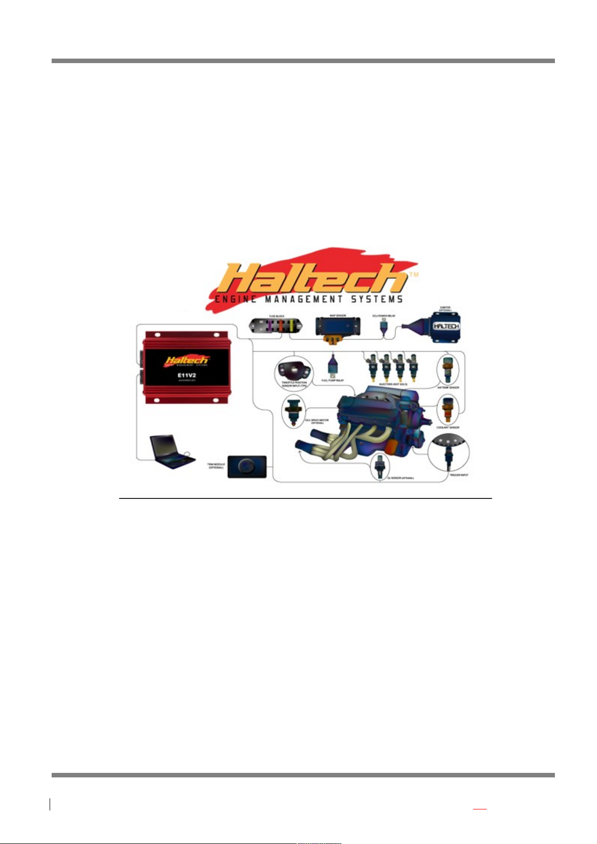
Introduction
Congratulations on purchasing a Haltech Engine Management System. This fully programmable product
opens the door to virtually limitless performance modification and tuning of your vehicle. Programmable
systems allow you to extract all the performance from your engine by delivering precisely the required
amount of fuel and ignition timing that your engine needs for optimum output under all operating
conditions.
This Installation and Wiring Guide will guide you through installing your Haltech ECU onto your vehicle.
This section accompanies the Setup Guide and Tuning Guide that you or your tuner will need to refer to
before completing your installation and configuration.
Before You Begin
IT IS BEST TO READ THIS ENTIRE MANUAL BEFORE STARTING.
At the very least, you should read Section One of the manual before you begin the wiring part of the
installation. The greater your knowledge of the operation of the Haltech system, the easier you will find it
to understand what you are doing, and why. Throughout the manual are Warnings and Notes that will
help your installation run smoothly and indicate the dangers that can exist for you the installer and the
Haltech ECU.
Read any additional material (if supplied) accompanying this manual that updates the document since it
was written.
You may need special parts or additional tools or test equipment in order to complete installation. Make
sure you have these items on hand before you begin to avoid frustration.
Don't do the minimum work possible. Carelessness in the early stages of installation can cause greater
problems later on. Carelessness will cost you money and frustration in finding and fixing unnecessary
problems. You have the opportunity to make sure your Haltech system's operation is extremely
dependable and easy to use by Doing it right the first time !. Another reason to exercise care during this
installation is make sure there is no Fuel leaks and no wiring un-insulated which can cause a spark or a
short and cause a fire or an explosion. Also make sure you follow the proper workshop precautions like
when working underneath a jacked-up car, make sure you use safety stands.
Page: 6
Copyright © Haltech 2008
Installation and Wiring Guide
Page 7

Haltech E11/E8 Instruction Manual
Electromagnetic interference (EMI) from unsuppressed spark plugs and high tension leads can cause the
ECU to fail. Please do not use them.
In hot climates, or with turbocharged engines, you may need to employ heat shielding to prevent heat
soak and damage to electrical and fuel parts. Use the coolest surfaces of the chassis as a heat sink for
components and shield any wiring that may be affected by heat.
We recommend having your system tuned by a Haltech Dealer or by a Workshop that has the proper
tuning equipment like exhaust gas analyser, fuel pressure meter, Dynamometer etc. Otherwise trying to
guess or tune by ear can lead to disastrous lean out conditions that could destroy your engine.
Note: In this manual, reference will be made to MAP (Manifold Absolute Pressure - as in MAP sensor) and
the fuel maps stored in the ECU. Both are common industry terms, with entirely different meanings.
Copyright © Haltech 2008
Page: 7
WARNING
Avoid open sparks, flames or operation of electrical devices near flammable
substances. Always disconnect the battery cables when doing electrical work on
your vehicle.
Do not charge the battery with a 24 Volt truck charger or reverse the polarity of
the battery or any charging unit. Do not charge the battery with the engine
running as this could expose the ECU to an unregulated power supply that could
destroy the ECU and other electrical equipment.
All fuel system components and wiring should be mounted away from heat
sources, shielded if necessary and well ventilated. Disconnect the Haltech ECU
from the electrical system whenever doing any arc welding on the vehicle by
unplugging the wiring harness connector from the ECU.
After completing the installation, make sure that there are no fuel leaks, and no
wiring left un-insulated in case a spark or short-circuit occurs and causes a fire.
Also make sure that you follow all proper workshop safety procedures. If you're
working underneath a jacked-up car, always use safety stands!
Page 8

Haltech E11/E8 Instruction Manual
Tools and Materials that you will need
Installation of this system can be easily carried out by professional mechanic(s) and most experienced
home mechanics if the following tools and components are available:
Voltmeter or Test Light
A selection of screwdrivers and spanners
Soldering Iron and solder
(It is recommended that all connections be soldered except where crimped terminations are used.
Soldering crimped terminations can cause the wire at the crimp to become weak. Most crimped
terminations have sufficient strength alone as long as the appropriate crimping tool has been used)
Wire Cutters and Pliers
Crimping Tool and assorted terminals
Drill with assorted drill bits
3/8" NPT Tap
14mm x 1.5 Tap
Electrical Tape or Heat Shrink tubing
Teflon pipe sealing tape
Nylon cable ties
Jeweller’s file (may be needed for mounting Throttle Position Sensor)
Mounting hardware for ECU and relays (mounts/bolts/screws)
Personal Computer (preferably a laptop or portable computer) running Windows 95/98, Windows 2000 or
Windows XP with an RS232 serial port. See section for the requirements of your PC.
A good quality Timing Light
Page: 8
Copyright © Haltech 2008
Page 9

Installation Guide
The installation guide will guide you through a typical installation. For details on the sensors and devices
mentioned here, see section on Devices and Pin Outs.
Flying Lead Loom Installation on bare engine
The following list outlines the procedure for installing the E11 ECU with a flying lead harness: Unpack your
ECU and identify the following components (some components may vary if you ordered a specific kit):
ECU
Main Wiring Harness
Coolant Temperature Sensor (purchased separately)
Air Temperature Sensor (purchased separately)
MAP Sensor (1, 2 or 3 Bar – purchased separately)
ECU Instruction Manual (which you are reading)
Programming Cable
Programming Disc with Programming Software
Fuse blocks and relays (on wiring harness)
Throttle Position Sensor (optional)
Idle Stepper motor (Optional)
Mounting Devices:
Locate a suitable location for the ECU. Ensure that the loom will reach the necessary parts of the engine
and mount the ECU.
Locate a suitable location for your Fuse block, fuel pump relay, ignition relay, injector relay, ECU relay and
any additional relays used for auxiliary devices (e.g. Thermofan, turbo timers, etc.). Mount all your relays.
Run the loom into the engine bay, but leave the ECU connector disconnected.
Inputs:
Connect the Throttle Position Sensor (TPS).
Connect the Coolant Temperature Sensor.
Connect the Air Temperature Sensor.
Connect the MAP sensor (optional).
Connect O2 sensor (optional).
Connect the crank angle sensor to Trigger (sometimes referred to as a crank trigger). Sometimes these
are driven off the cam, but still give a crank position. Leave the wiring in such a way so that changes to
sensor wiring can be made if required when setting up.
Connect any cam angle sensors if applicable to the Home input. Leave the wiring in such a way so that
changes to sensor wiring can be made if required when setting up.
Outputs:
When running the wiring for outputs, run any power and ground wiring back to the points where they will
be connected, but do not connect power or ground connections yet.
Run the injector wires within the loom to the fuel injectors (each injector shares a common +12V with the
Note: Installation of engine management systems is a complex exercise to be undertaken
only after careful planning and research into the application for which the product is to be
used. Damage to engine components is a distinct possibility if care is not taken during the
installation and setup of the Haltech Engine Management System. If you are unsure about
how to wire any components of your engine, please consult Haltech or an experienced
installer for advice.
Page 10

Haltech E11/E8 Instruction Manual
wires labelled “injector output” from the ECU providing the ground to switch the injector on and allow the
fuel to flow).
Connect your fuel pump back to the fuel pump relay.
Run the loom from all ignition outputs to ignition modules (often called ignitors or spark amplifiers) but
leave the ignition modules disconnected at this stage. See warning at beginning of manual. Connect
ignition modules to coils and run wiring for coil(s) power supply back to the relay.
Connect idle control motors if applicable.
Connect any other auxiliary devices such as thermo-fans or turbo wastegate solenoids.
Power & Ground:
Connect all ground connections to a central location, any unused black wires in the wire harness can be
grounded.
Connect power from the battery to the fuse block. Try to keep the wires from the battery to fuse block short
and ensure that this run of wire is well protected from damage to its insulation in case of a short circuit.
Connect power from the fuse block to each relay that supplies power to injectors, ignition, ECU and any
other auxiliary devices that require a switch 12V supply.
Ensure that the ignition modules and fuel injectors are disconnected at this stage.
Connect the ECU to the loom and connect a laptop computer to the D9 serial connector. Proceed to the
Setup Guide.
Page: 10
Copyright © Haltech 2008
IMPORTANT INSTALLATION NOTE !!
To avoid damage to ignition components, never connect the ignition modules
to the ECU until the ECU is configured. The same applies to the Fuel System,
never connect fuel injectors until the ECU is configured, otherwise the engine
may flood with fuel.
When wiring a Haltech ECU, it's extremely important that you have good
connections to the vehicle's electrical ground and battery power. If possible,
supply power to the fuel injectors, ECU and ignition system directly from the
positive terminal of the 12V Battery (via relays). Don't just look for any wire
that has 12 volts while the ignition is on, and assume that's good enough.
Trying to get power from unknown wires causes many problems and makes it
very hard to diagnose a fault. That wire may have a large voltage drop, or be
picking up electrical noise which can interfere with the ECU. Avoid running
wires next to starter motor cables or ignition coils and their wiring, including
high tension Leads. Also keep the ECU's wiring away from the antenna cables
of radio transmitting equipment (e.g. CB, UHF radios) and cables from high
powered car audio systems. All can cause ECU malfunctions.
When crimping cables, use a good crimp tool. After crimping each connector,
pull on the cable and connector and make sure that it doesn't come loose. If
you're soldering connections, make sure that you have a large enough
soldering iron to ensure that the joint gets hot enough and allows a good flow
of solder onto the wires. Some cheap or faulty irons just barely melt the
solder, which only sticks to the wire instead of making a good solder
connection. Properly insulate all connections.
Page 11
Haltech E11/E8 Instruction Manual
Sensors and Device Pin Outs
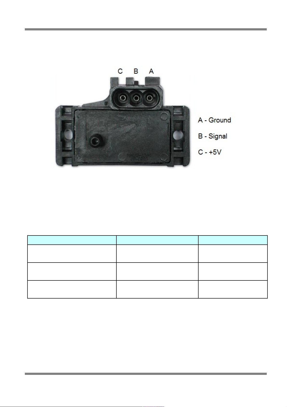
Manifold Absolute Pressure Sensor
Figure 1 - MAP Sensor
The MAP sensor is used to convert the manifold pressure into an electrical signal for the ECU to use. The
sensor works in absolute pressures, thus its calibration is not affected by changes in barometric pressure.
The vacuum and, in the case of forced air induction engines, the pressure under boost, is proportional to
the load under which the engine is operating and the ECU uses the electrical signal as a load reference.
There are three types of MAP sensors that can be used with the system. Which sensor is required
depends on the engine set-up.
Sensor Name Range of Operation Application
1 Bar Sensor (Part No. 039 4070)
(Green plug)
-100kPa to 0 kPa Normally Aspirated Engines
2 Bar Sensor (Part No. 886 3189)
(Orange plug)
-100kPa to 100kPa
(15 psi of boost, 1 atmosphere)
Turbo or Supercharged
Engines up to 100kPa boost
3 Bar Sensor (Part No. 749 3169)
(Orange plug)
-100kPa to 200kPa
(30 Psi of boost, 2 atmospheres)
Turbo or Supercharged
Engines up to 200kPa boost
Note: Make sure you have the correct MAP sensor for your engine. The first three digits of the part
number are stamped on the sensor housing.
The MAP sensor is usually mounted high on the engine bay firewall or inner guard using two screws and
with the hose nipple facing outwards. Connect the sensor to the inlet manifold via a short length of
vacuum hose and fasten with either hose clamps or nylon cable ties. Connect the sensor to the main
wiring harness using the appropriate plug. Avoid mounting the sensor below the level of the fuel injectors,
because fuel may collect in the vacuum hose and run down into the sensor. The sensor assembly is
weatherproof but it is good practice to mount the sensor in a protected position away from moisture and
heat.
Copyright © Haltech 2008
Page: 11
Page 12
Haltech E11/E8 Instruction Manual
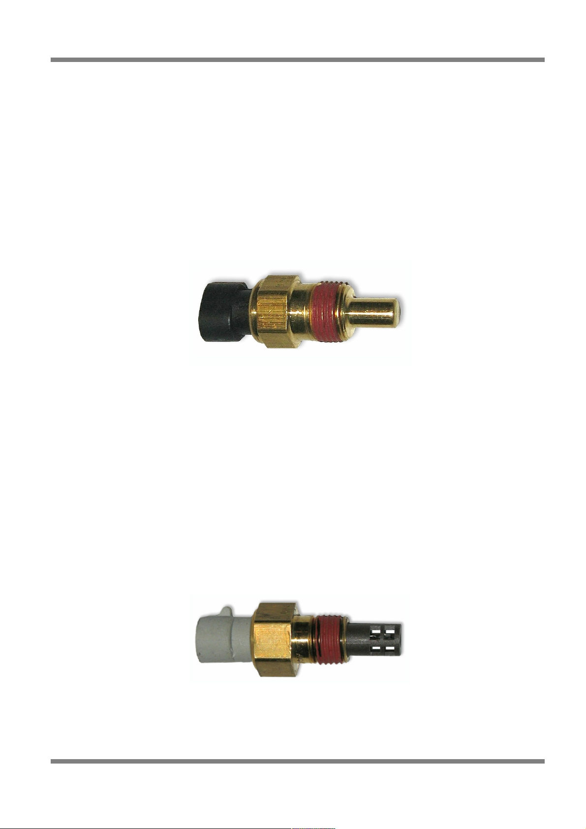
Coolant Temperature Sensor
The coolant temperature sensor has a solid brass temperature-sensing tip. Refer to the diagram for
physical details of the sensor at the back of this manual. The coolant sensor supplied is an industry
standard component and some engines may already have provision for this type of sensor.
The coolant temperature sensor is designed to screw into a threaded hole and protrude into the engine
coolant stream. For air-cooled engines, the sensor can be embedded directly into the engine block or
used to sense oil temperature.
Locate a suitable position on the engine which gives access to the coolant stream before you drill and tap
the thread. The sensor should be mounted before the thermostat in the coolant circuit. Since most
engines have existing temperature sensor holes, it is often possible to mount the Haltech sensor in one of
these holes. If necessary drain the coolant from the vehicle to fit the temperature sensor then consult the
factory manual on how to purge the cooling system of air and check the engine does not require toppingup with coolant after the engine has reached operating temperature.
Figure 2 - Coolant Temp Sensor
Inlet Air Temperature Sensor
The air temperature sensor is used to compensate for changes in air density due to air temperature. Cold
air has a higher density than warm air and therefore requires a greater volume of fuel to maintain the
same air/fuel ratio. This effect is most noticeable in forced induction engines. The Haltech ECU will
automatically compensate using the signal received from the air temperature sensor (once the air
temperature correction map is setup and enabled in the programming software).
The sensor should be mounted to provide the best representation of the actual temperature of the air
entering the combustion chamber, i.e. after any turbo or supercharger, and intercooler, and as close to the
head as possible. The sensor needs to be in the moving air stream to give fast response times and reduce
Heat-Soak effects. Be aware in some situations, mounting the sensor into the inlet manifold (especially at
the rear) may case Heat Soak problems.
Once a suitable position has been located for the air temperature sensor a hole should be drilled and
tapped to accept the sensor. Remove the manifold or inlet tract from the engine before this is done so you
don’t get any metal particles entering the inlet manifold, as these will be drawn into the engine and may
cause damage.
Figure 3 - Air Temp Sensor
Note: The Haltech air temperature sensor will read temperatures up to 120° C and temperatures above
this will be interpreted as a fault condition. The air temperature after some turbo and superchargers can
exceed this. If this occurs with your engine you should consider fitting an intercooler to reduce air
temperature and increase charge density.
Page: 12
Copyright © Haltech 2008
Page 13

Haltech E11/E8 Instruction Manual
Throttle Position Sensor
Figure 4 - Throttle Position Sensor
The throttle position sensor is mounted to the throttle butterfly shaft to measure its rotation. A TPS is
common on many late model engines and the Haltech sensor should attach with little or no modification.
The throttle shaft must protrude from the side of the throttle body. This may require the machining of the
throttle body or the manufacture of a new throttle shaft. The inner mechanism of the sensor rotates with
the shaft. If the shaft is round then file a flat surface on the shaft so that it will pass through the sensor
assembly. The TPS should be mounted against the side of the throttle body, using two screws, such that
the throttle shaft and the sensor mechanism can rotate freely. The absolute range of sensor movement is
not important as the sensor can be calibrated using the programming software.
Your engine may have a Throttle position sensor already fitted and it is often possible to make use of this
TPS. The Haltech supplied TPS has a resistance value ranging from 0 to 10kΩ. The resistance value of
the installed TPS does not have to be the same since the ECU uses a throttle calibration function to
determine the position of the throttle based on the signal received from the TPS. Be sure to wire the TPS
so that the ECU sees a lower value when at zero throttle than at full throttle.
Note: Make sure that the axis of rotation of the shaft is exactly aligned with the axis of rotation of the
sensor, otherwise some binding may occur. Also, do not use the TPS as a throttle stop. In either case, the
TPS will be damaged.
Ignition Modules
The Ignition Module should be mounted on a flat surface (eg. the firewall) to ensure proper heat
dissipation and to avoid stress on the wiring connections. It is also important to prevent the module
overheating by mounting it away from hot components such as exhaust manifolds and turbochargers.
Included with your ignition module, should be a wiring diagram for your ignition module. Follow the
directions on these instructions to connect your ignition module(s) to your main wiring harness. Locate the
ignition wires in the main loom. Using the supplied pins, crimp the pins onto the appropriate wires and
insert them into the appropriate locations in the ignitor plug, but do not connect it to the ignitor until the
ignition settings in the ECU are verified by connecting the ECU to a computer with Haltech programming
software.
Copyright © Haltech 2008
Page: 13
Page 14
Haltech E11/E8 Instruction Manual
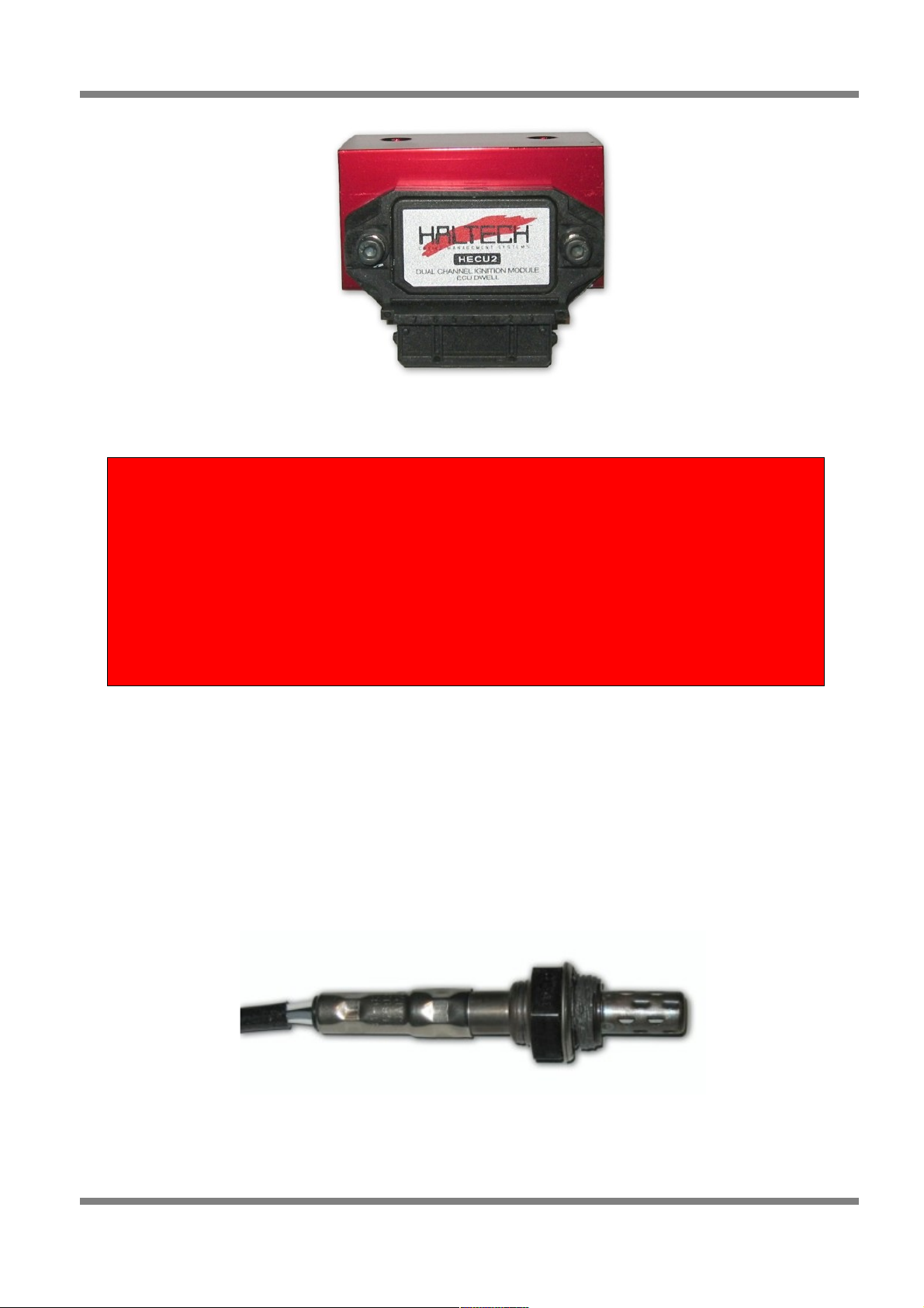
Figure 5 - Haltech Dual Channel Ignition Module
Exhaust Gas Oxygen Sensors (Optional)
The optional exhaust gas oxygen sensor must be mounted in the exhaust pipe near the exhaust header or
extractors, usually after the collector. The sensor uses the exhaust gas to detect if the engine is lean or
rich. Many late model engines already have provision for an exhaust gas oxygen sensor and the sensor
provided should fit any standard exhaust mount. Some exhaust systems have the sensor mount up to
around half a meter (2 feet) down stream from the exhaust headers.
If the exhaust system does not have an existing sensor mount then a new mount will have to be welded to
the exhaust system. When routing the electrical connections to the exhaust gas oxygen sensor do not
allow the harness to touch the exhaust pipe, as the heat will damage them.
Figure 6 - O2 Sensor
Page: 14
Copyright © Haltech 2008
Warning
If using “Intelligent” ignitors such as the old Bosch 008 ignition module
(rare), Constant Duty Cycle Mode should be selected in the Ignition Setup
Page. If using a “Dumb” ignitor (Most standard ignitors are dumb, as are
modern Haltech ignitors), the Constant Charge Mode should be selected in
the ignition setup page.
Do not connect the ignition sub-loom to the main wiring loom until after
you have configured the ECU by connecting it to a computer with Halwin
programming software.
Page 15
Haltech E11/E8 Instruction Manual
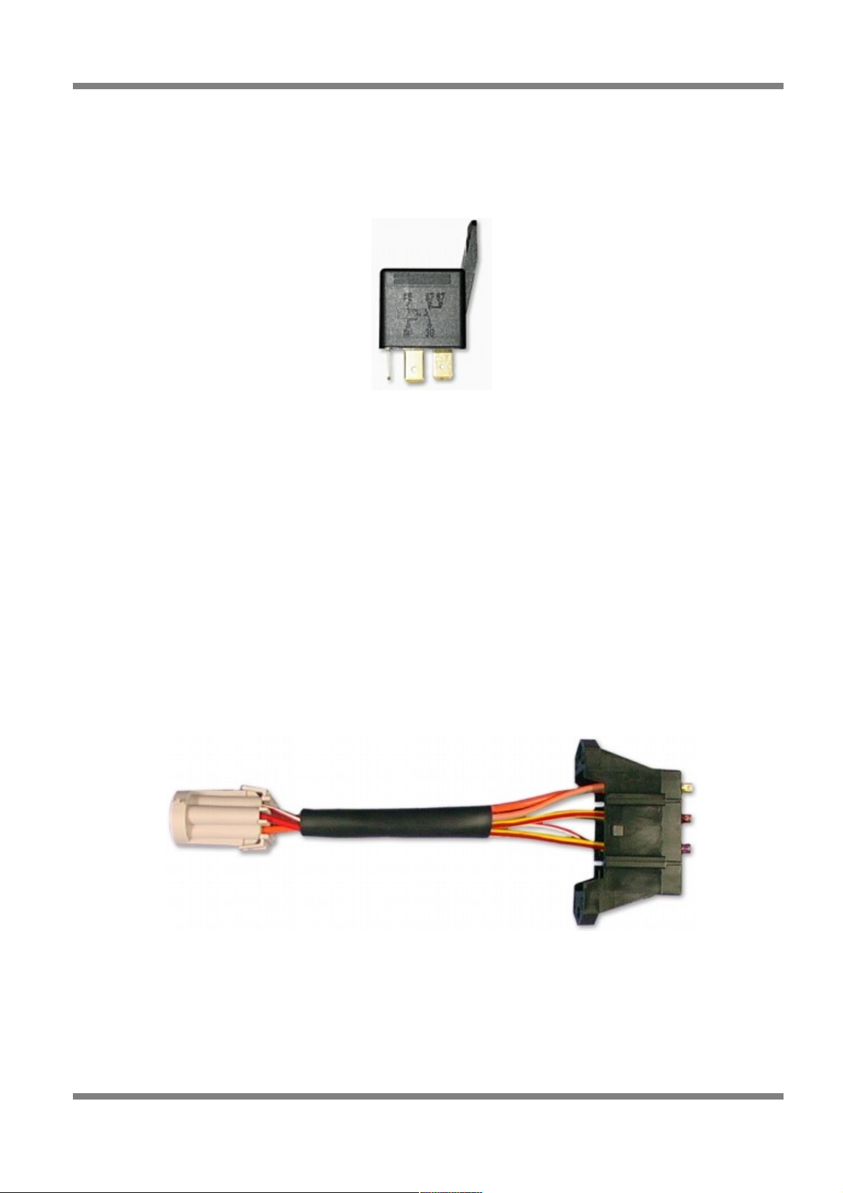
Power Relays
There are three relays used with the Haltech ECU, the main power relay, the ignition relay and the fuel
pump relay. These relays look almost identical, to determine which relay should go into which connector
the diagram on the side or top of the relay will need to be compared to the diagram in the Haltech wiring
diagram.
Figure 7 - Power Relay
These relays should be mounted on the firewall or an inner guard. Do not mount the relays such that they
could catch and collect splashed water. Residual water inside the relay housing will cause them to fail.
Mount them with the tab upwards as shown in the diagram.
Fuse Block Assembly
The fuse block assembly holds the fuses that protect the various components of the engine management
system.
The fuse block is supplied from the factory with fuses installed. The fuse ratings and connections are
shown in the wiring diagram at the end of the manual. The fuse ratings have been selected to protect the
Haltech ECU and the electrical systems that supply it. Fuse ratings should only be changed if the
expected normal load current exceeds the factory specification. Altering the fuse ratings could cause
severe damage to the system.
The fuse block should be positioned so that it can be accessed easily in case of fuse failure. Do not mount
the fuse block where it could be exposed to water. Mount the fuse block using the two screws holes in the
block ensuring that vibration will not cause the screws to vibrate loose.
Figure 8 - Fuse Block
Trigger Wiring (Crank and Cam Angle Sensors)
The most critical sensor on the engine is the engine speed sensor, without this sensor the ECU would not
know that the engine is moving and therefore it would never fire a spark nor inject any fuel.
The ECU gets information from the crankshaft and camshaft position sensors in the form of electrical
impulses over a period of time. When the ECU knows what pulses to expect it can compare this to what
pulses it receives and determine the engine speed and position at any point in time.
Copyright © Haltech 2008
Page: 15
Page 16
Haltech E11/E8 Instruction Manual
There are two main types of sensor used for this application;
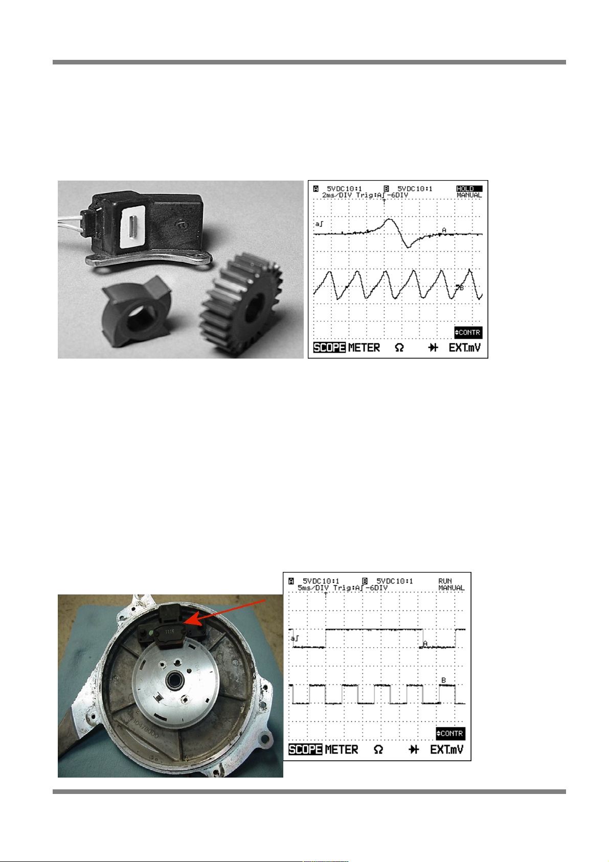
Reluctor Sensor Types
Variable Reluctance Transducers (VRT or simply reluctor) – this kind of sensor produces a sine wave
output. Generally a VRT sensor will have only 2 wires (a third wire may be present but its generally a
shield wire to help protect the signal from “noise”).
VRT sensors DO NOT require a power supply, they will have a signal wire and a ground wire only, the
way they work is almost the opposite of an electric motor with only one brush where the sensor has a
magnet inside with a coil of wire wrapped around it. As a ferrous material passes by the magnet the
magnetic field is disrupted and a voltage spike is created in the coiled wires surrounding the magnet
producing a sine wave. This signal is what is fed into the ECU. The ECU cannot interpret a sine wave
directly and must first process the sine wave into a digital signal before it is able to use this information.
The part of the ECU hardware that conditions the reluctor signal is called a reluctor adapter and it converts
the reluctor signals shown above to a square waveform similar to that of the Hall effect trigger. The
reluctor adapter and its tuning is dealt with in detail further later on.
Hall Effect Sensor Types
The second type of sensor found of crank and camshafts known as a Hall Effect (this includes optical
sensors) sensor. This style of sensor has a transistor and some electronics built into the sensor itself and
will generally require a power supply and ground of some sort. For this reason a hall effect sensor usually
has at least 3 wires. The output of this style of sensor is a digital square wave.
Page: 16
Copyright © Haltech 2008
Figure 9: Reluctor Style Sensor Figure 10: Reluctor Scope Trace
Figure 11: Hall Effect Sensor (Optical)
Page 17
Haltech E11/E8 Instruction Manual
Because the output from a hall effect sensor is already in digital form the ECU does not need to do any
signal conditioning to be able to use it.
When given the option a hall effect sensor is always the best option to put on an engine and it reduces the
amount of work required of the ECU.
In applications where either direct fire ignition or sequential fuel injection is required the ECU must have a
way of determining where it is in the firing order at any point in time and which cylinders are on
compression and which are on exhaust. The only way of determining this is to use a sensor connected to
the camshaft that sends a signal to the ECU when the engine is approaching cylinder 1 TDC on the
compression stroke.
Flying Leads
Locate and connect the following flying leads.
Black (Ground)
Locate a good chassis ground point or the negative terminal of the battery and connect the black wire.
Red
(Battery Supply +12V) Locate a source of continuous +12 volts and connect the red wire. Connecting
direct to the positive battery terminal is suggested.
Grey
(Ignition Switched +12V) The grey wire is used to control the operation of the Haltech ECU power relay. It
needs to be connected so that it sees 12V only when the ignition switch is on and during cranking. This
wire does not draw a large amount of current (< 0.5A). Do not connect to the accessory outputs of the
ignition switch.
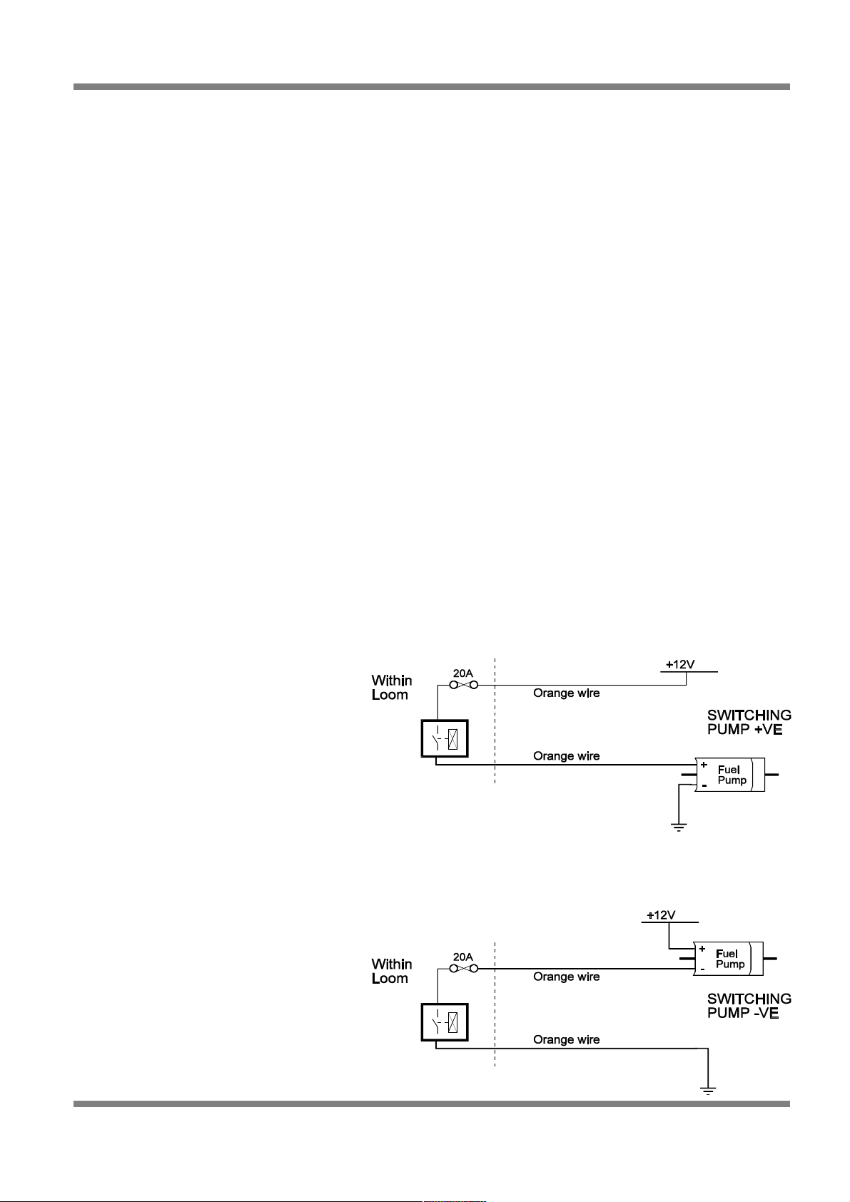
Orange
The two orange wires are used to operate the fuel pump. When the Haltech ECU wants to operate the fuel
pump it will close the fuel pump relay connecting the two orange wires together. The diagrams show two
examples of wiring the fuel pump. Do not add extra relays to the fuel pump circuit.
Figure 12 - Fuel Pump Wiring
It does not matter which example is used.
Both will operate correctly. Note that the
orange wires are connected internally
within the loom when the relay is closed.
As a result it does not matter which
orange wire is used to connect to the fuel
pump.
Copyright © Haltech 2008
Page: 17
Page 18

Haltech E11/E8 Instruction Manual
Wiring Injectors
When wiring fuel injectors all Injectors share a common +12V supply voltage with the ECU INJ output
supplying the ground for the injector when fuel delivery is required. It is also essential for the +12V supply
voltage to the injector to be the same +12V supply that goes to the ECU. If using the Haltech long flying
lead harness this is already preterminated, if you are wiring your own harness you will need to ensure you
make this connection.
When wiring E8 or E11 for sequential fuel injection, fuel injectors should be wired with inj1 output to
cylinder 1, inj2 output to cylinder 2 and so on, the injectors firing sequence will be set in the software via
the firing order found on the advanced tab of the main setup page. If semi-sequential injection mode is
used the injection sequence will always be Inj1, inj2, inj3 inj 4 etc regardless of the firing order set in the
software.
Wiring Ignition
See below for some tables describing typical ignition wiring layouts
On the E8 and E11v2 ECU’s an external ignition amplifier (otherwise known as an ignition module, an
ignitor or ignition power transistor) is required. Some Ignition coils have these modules built into the coil
itself, others do not. As a general rule of thumb any coil with only 2 wires does NOT have the ignition
module built into it, you will need an additional ignition amplifier on these coils. If in doubt of your ignition
module requirements call your Haltech representative or the manufacturer of the ignition system.
When wiring E8 or E11 for direct fire ignition, ignition outputs should be wired with ign1 output to cylinder
1, ign2 output to cylinder 2 and so on, the ignition firing sequence will be set in the software via the firing
order found on the advanced tab of the main setup page. If wasted spark ignition is used the ignition
sequence will always be Ign1, ign2, ign3 ign 4 etc regardless of the firing order set in the software.
Distributor Ignition
Distributor ignition output is always on IGN 1.
Twin Distributor Ignition
Ignition output will always appear on IGN 1 and IGN 2 channels. In the majority of cases, IGN 1 will be the
first output to fire.
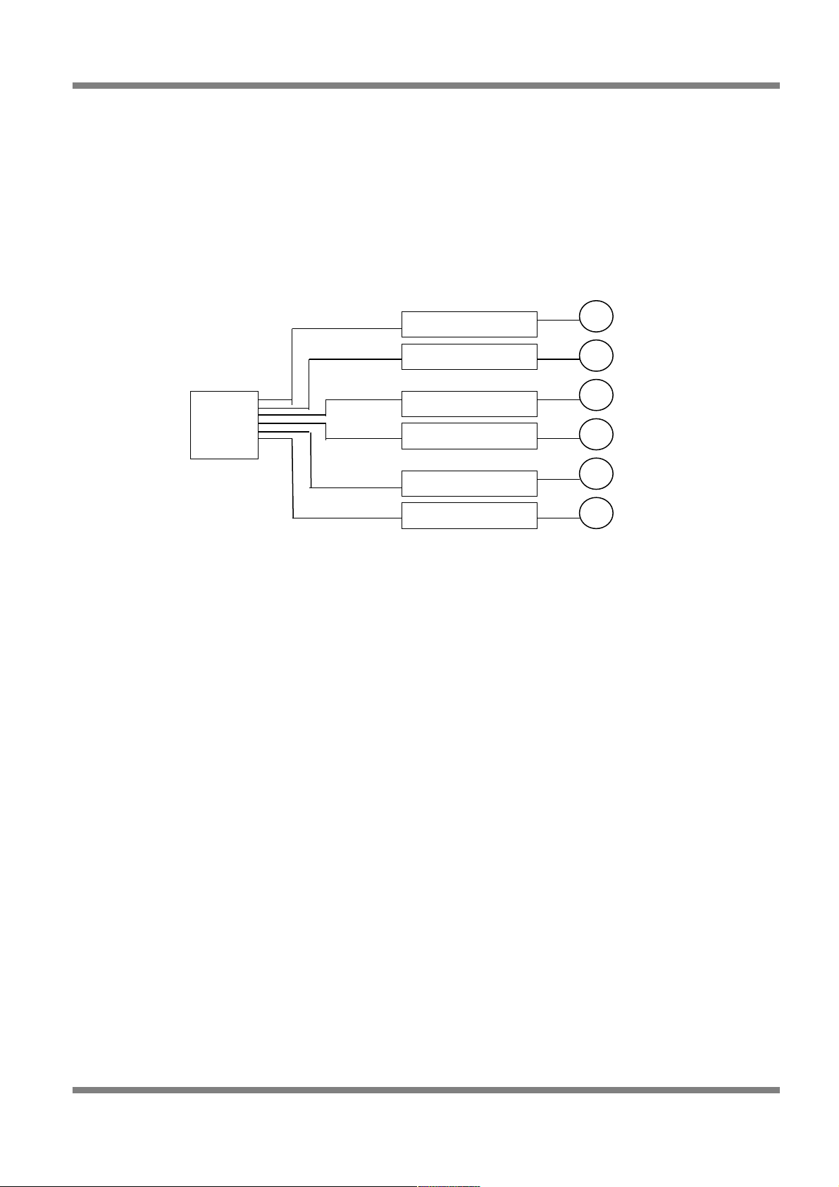
Waste Spark Ignition
When setup for waste spark ignitions, the order of the ignition outputs is simply in the order of the outputs.
IGN 1 will fire first, then IGN 2 will fire next etc until the last ignition channel is reached regardless of
engine firing order. The following example is for a 6-cylinder engine that fires 1-5-3-6-2-4.
Figure 13 - Waste Spark Ignition Configuration
Page: 18
Copyright © Haltech 2008
1
2
3
4
5
6
Ignitor
+ Coil
1
Ignitor
+ Coil
2
Ignitor
+ Coil
3
ECU
IGN1
IGN2
IGN3
Page 19
Haltech E11/E8 Instruction Manual
Direct Fire Multi-Coil Ignition (1 coil per cylinder)
Wire each ignition output to its corresponding coil with IGN1 output wired to cylinder 1’s coil/Ignitor, IGN2
output wired to cylinder 2’s coil/Ignitor etc. The firing order for ignition will be taken from the firing order
that is specified in the Main Setup in the programming software. Its important to note the difference in
wiring order between direct fire and wasted spark – in direct fire mode the ECU will fire the ignition outputs
according to the firing order entered into the software where as in wasted spark mode the ECU will
disregard what is in the software and fire the ignition outputs in the order of the Haltech ignition output (ie
IGN 1, IGN2, IGN3 etc.) Note: E8 ECU is only capable of driving 4 individual coil channels, and can
therefore only do direct fire on a 4 (or less) cylinder engine.
Figure 14 - Direct Fire Ignition Configuration
Copyright © Haltech 2008
Page: 19
1
2
3
4
5
6
ECU
IGN1
Ignitor + Coil 1
IGN2
Ignitor + Coil 2
IGN3
Ignitor + Coil 3
IGN4
Ignitor + Coil 4
IGN5
IGN6
Ignitor + Coil 5
Ignitor + Coil 6
Page 20

Haltech E11/E8 Instruction Manual
This section will guide you through setting up the software and calibrating the necessary values to enable
you to start your engine and achieve a steady idle. By the end of this section, the vehicle will not be ready
to be driven, but will be ready to be tuned which is described in the Tuning Guide in section 3.
This setup guide assumes basic knowledge of automotive fuel, ignition and triggering systems. If you find
settings or concepts that are confusing or difficult to understand, please refer to the appendices of this
manual for more background information on these topics.
It is assumed that you are competent with operating your personal computer and are familiar with the
basic concepts of the Windows operating system environment. The Halwin software and this manual have
made every possible attempt to keep the setup procedure simple. This section will cover only the bare
minimum information required to operate the Halwin software package for the setup procedure outlined.
For more details on the advanced features, make sure that you read section – The Halwin User Guide.
Halwin Programming Software
Computer Requirements
The programming software requires a PC running Windows 95 release 2, Windows 98, Windows 2000,
Windows Millennium or Windows XP with the following specifications.
Minimum Requirements:
233MHz processor
VGA colour display 800x600 (preferably 1024x768)
4Mb of memory
10 MB of free Disk space
Installing Halwin
Installing Halwin onto your PC is performed similar to any other Windows software package. Installation is
outlined below to ensure correct installation:
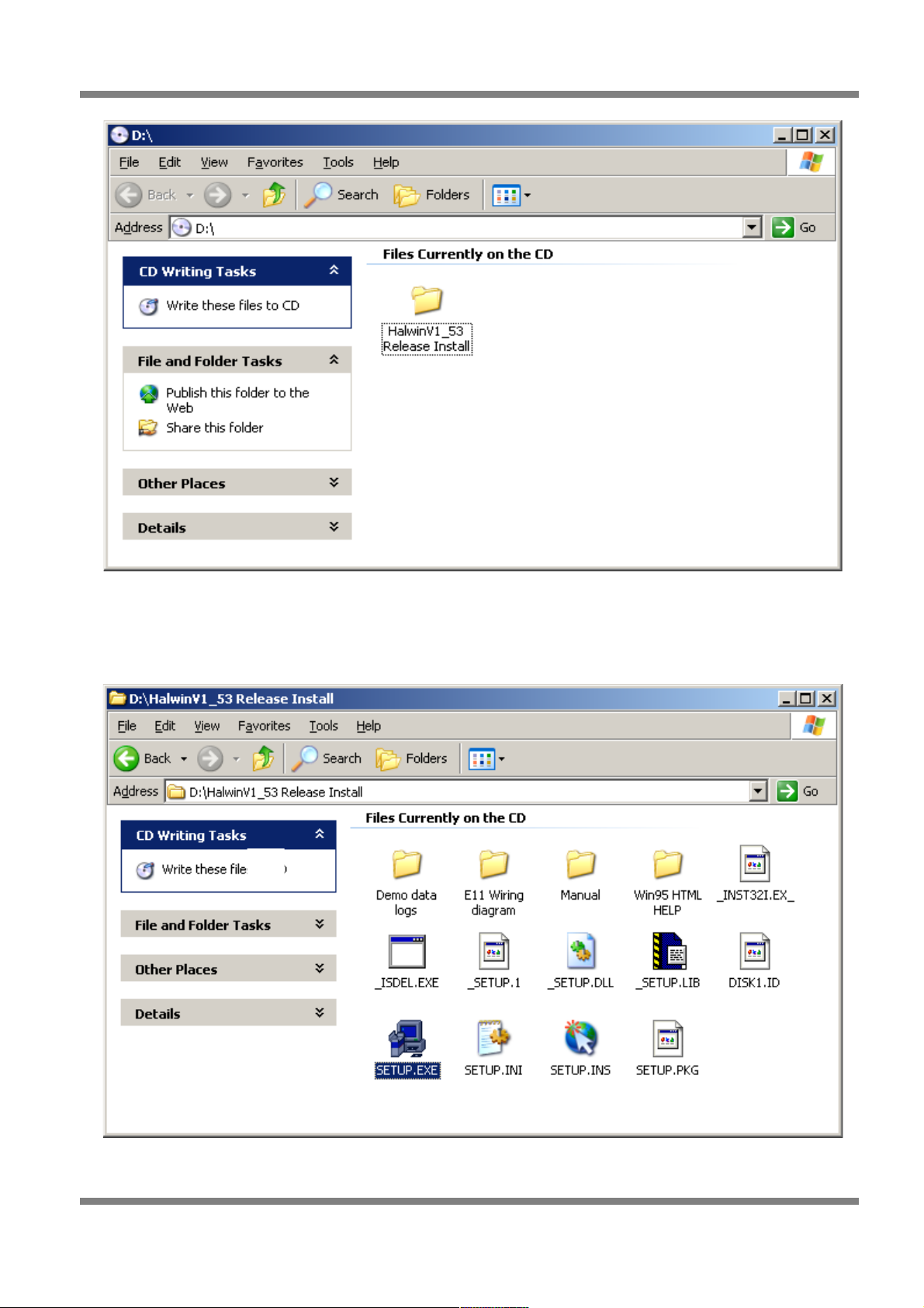
Insert the CD-ROM into your PC’s CD-ROM drive.
Run the executable file “SETUP.EXE” from the CD-ROM drive. Continue at step 3. Otherwise, skip ahead
to step 6. (Note: on some later Software versions, the disk may auto-run setup.exe)
Double click on the “My Computer” icon on the desktop.
Page: 20
Copyright © Haltech 2008
Setup Guide
Note: Haltech will NOT provide support on operating your PC
Page 21
Haltech E11/E8 Instruction Manual
Figure 15 - Halwin Software Installation
Double click on the CD-ROM icon to open the CD-ROM. If the setup software does not automatically
open, then double click on the “SETUP.EXE” icon to start the setup software.
Figure 16 - Halwin Software Installation
Copyright © Haltech 2008
Page: 21
Page 22
Haltech E11/E8 Instruction Manual
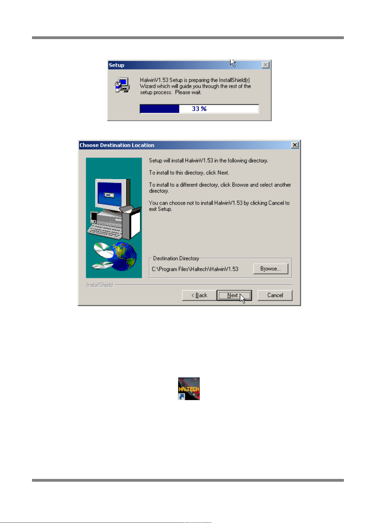
After double clicking on the ‘SETUP.EXE’ icon, the following screens will appear.
Figure 17 - Halwin Software Installation
Figure 18 - Halwin Software Installation
Click on ‘Next >’ to continue and follow the instructions given to you on the windows that appear.
When prompted for which type of installation to perform, choose ‘Typical’ if you are unsure.
Starting Halwin
After installing the software, an icon should appear on your desktop similar to the one shown in the picture
below.
Figure 19 - Halwin Icon
Double click on the icon to start Halwin.
Page: 22
Copyright © Haltech 2008
Page 23
Haltech E11/E8 Instruction Manual
Powering Up for the first time
Going Online with the Software
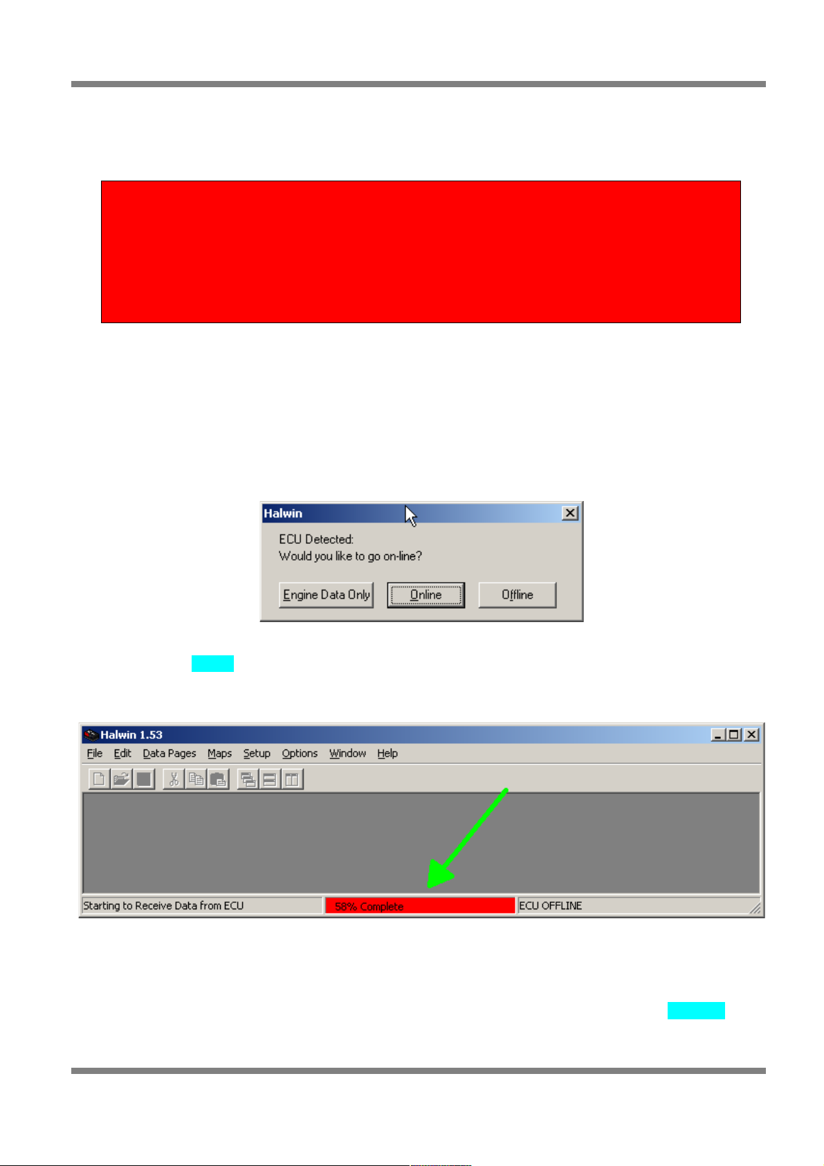
With your programming cable (RS232) attached to your ECU and the other end connected to your laptop,
power up the ECU by turning your key to IGN. Start the programming software on your PC. The following
window will appear on the screen when the software detects the ECU connected and able to communicate
with the software. If you do not get this window displayed, then check your ECU power and serial
connection. If you are using a USB/Serial adaptor ensure that the adaptor is emulating the same port that
you have selected for communications in the program setup tab of Halwin (default is COM1 in Halwin).
Figure 20 - Halwin Online Prompt
Select the option Online. This will load the map from the ECU into the programming software. The status
indicator will show how much of the map has been loaded.
Figure 21 - Halwin loading map
After the map has been loaded into the ECU, the status indicator will show that the ECU is ‘ONLINE’.
When Online, all changes made to the maps will be sent to the ECU. When operating the software Online,
some caution is required as some changes are applied immediately in real time.
Copyright © Haltech 2008
Page: 23
WARNING
Now is the time to double check that your ignition modules and fuel
injectors are not connected to the ECU. Powering up the ECU with the
wrong configuration can lead to damage to your ignition modules and/or
ignition coils or excessive fuel deposited in your engine if you leave these
devices connected.
Page 24
Haltech E11/E8 Instruction Manual
Figure 22 - Halwin Online
Setup Menus
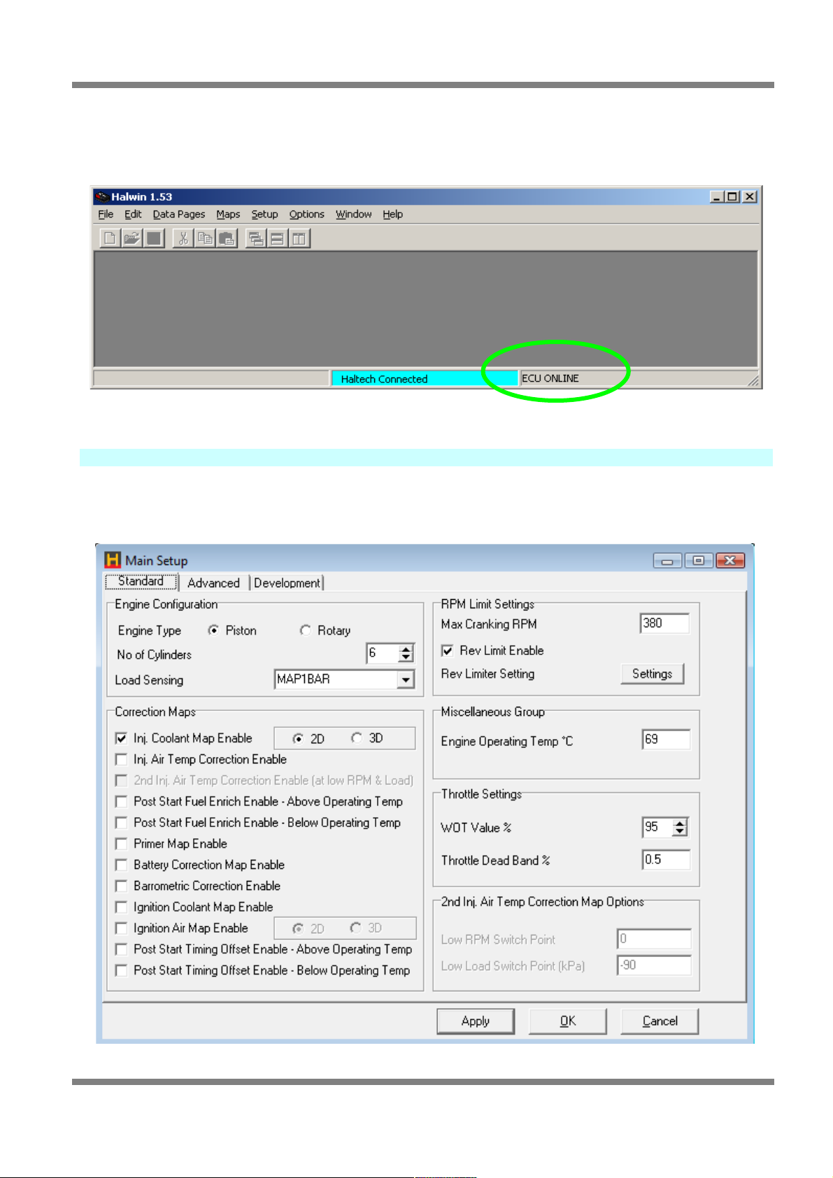
Main Setup
If the map for your engine is unavailable for your vehicle, then you will need to create your own settings by
following through the settings below.
Figure 23 - Main Setup
Page: 24
Copyright © Haltech 2008
Page 25
Haltech E11/E8 Instruction Manual
Engine Config Group
• Engine Type – Select your Engine type, Piston (reciprocating) engine or Rotary engine.
• No of Cylinders - Set this field to the number of cylinders your engine contains if you are
configuring for a piston engine
• No of Rotors – Set this field to the number of Rotors when configured for a Rotary engine Type.
• Load Sensing - Set this to match the load sensing method you are using. Most engines will
operate using manifold pressure to sense engine load. If your engine employs any form of
supercharging or Turbo charging, select a suitable MAP sensor range. Engines with wild cams,
most motorbikes, multi-throttle bodies or heavily ported rotaries will require a TPS as the load
sensing. If you are unsure what to use, contact your Haltech dealer.
Correction Maps Group
Click on the checkboxes on the left to place a tick next to the correction maps that you wish to have
enabled. To disable a map, click on the checkbox to clear the tick. Choices are Inj Coolant Map, Inj Air
Temp Correction Enable, Post Start Enrich Enable, Primer Map Enable, Post Start Type, Battery
Correction Map Enable, Barometric Correction Enable, Ignition Coolant Map Enable. Ignition Air Map
Enable and Post Start Timing Offset.
RPM Group
• Max Cranking RPM - When the engine RPM is below this value, the engine is considered to be
cranking under the starter motor power. When the RPM exceeds this value, the engine is
considered to be started and running. This allows the ECU to determine what is Cranking and what
is Running.
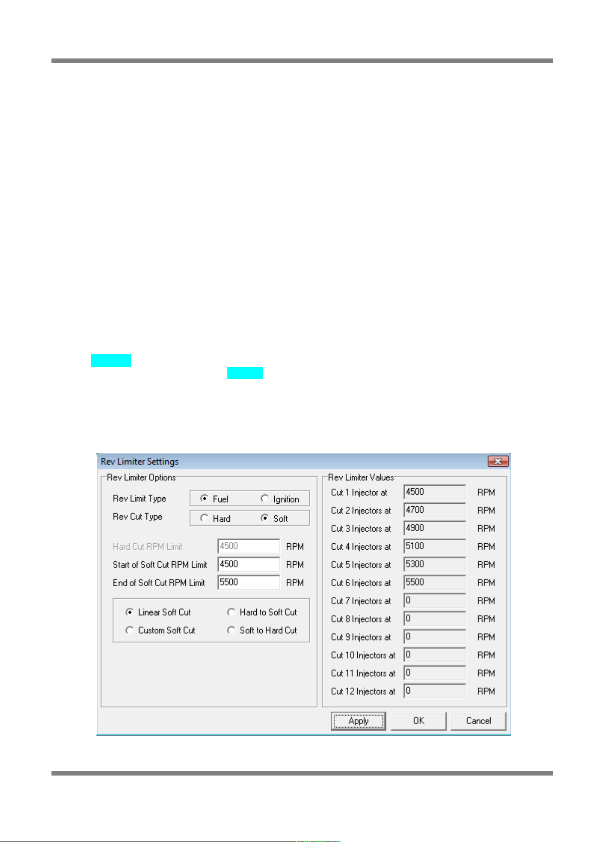
• Rev Limit Enable - Click on this checkbox if you want to enable the Rev Limiter.
Rev Limiter Options Group
Figure 24 - Rev Limiter Settings
Copyright © Haltech 2008
Page: 25
Page 26

Haltech E11/E8 Instruction Manual
• Rev Limit Type – Select which output the Rev Limiter will use - Fuel or Ignition.
Note: Be careful when using “Ignition” for Rev Limiting on vehicles with
Catalytic Converters. Unburned fuel can overheat and damage the
converter.
• Rev Cut Type – The method for cut-out to Ignition or Fuel can be either Hard or Soft. Hard cut is
an instant stop to Fuel or Ignition and Soft Cut is a progressive or gradual cut (see figure xx).
Selecting Hard Cut with Fuel as the Rev Limit Type, the injection time will be set to Zero if the
RPM exceeds the value set in the RPM Limit field. If Ignition is used as the Rev Limit Type, then
spark charge Time will go to Zero when RPM exceeds the value in the RPM Limit field. When
using Soft cut, you can choose the type of sequence or aggressiveness of the cut by selecting
Linear, Hard to Soft, Soft to Hard or a Custom style.
Figure 25 - Soft Cut Rev Limiter
Miscellaneous Group
• Engine Operating Temp - When the coolant temperature is below this temperature, the engine is
considered to be cold. Features such as injector primes that depend upon operating temperature
will use this temperature to decide if the engine is at operating temperature.
Throttle Group
• WOT Value % - Wide Open Throttle (WOT) value. When using Full Throttle Maps, this threshold
defines over what percentage a full throttle map will work at. Example: if you set WOT value say
95% and WOT Map is enabled (Setup/Fuel Setup/Maps Group), when the Throttle position
exceeds 95% the Full Throttle Map will take effect.
• Throttle pump Dead Band - Some Throttle Position Sensors (TPS) may have some residual
noise. When watching the Engine Data page you may notice the TPS value move slightly even
when no physical throttle movement is present. In some cases having a worn throttle shaft or
multiple throttle bodies, engine vibration may cause throttle movement which can trigger a Throttle
Pump Correction (causes an unexpected rich fuel mixture at idle or at a light load). If you think this
Page: 26
Copyright © Haltech 2008
4900 5000 5100 5200 5300 5400 5500 5600
Soft to
Hard
Linear
Hard to
Soft
Page 27
Haltech E11/E8 Instruction Manual
is causing a problem, then increase the Dead Band value slightly higher than the jitter or
fluctuation value read from the TPS Engine Data Page reading. Typical values are around 0.5% to
2%.
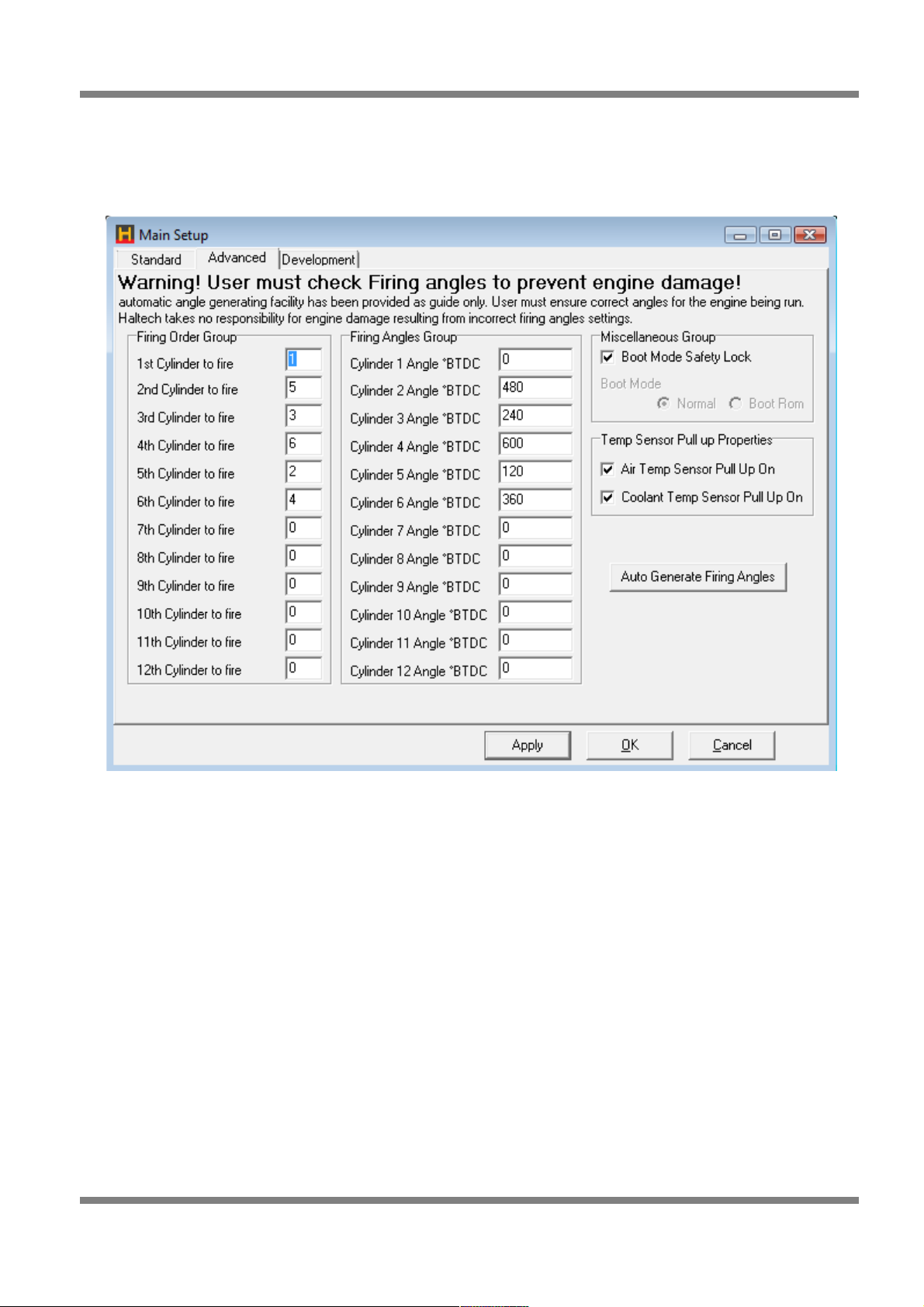
Main Setup - Advanced Tab
Figure 26 - Advanced Setup Window
Copyright © Haltech 2008
Page: 27
Page 28
Haltech E11/E8 Instruction Manual
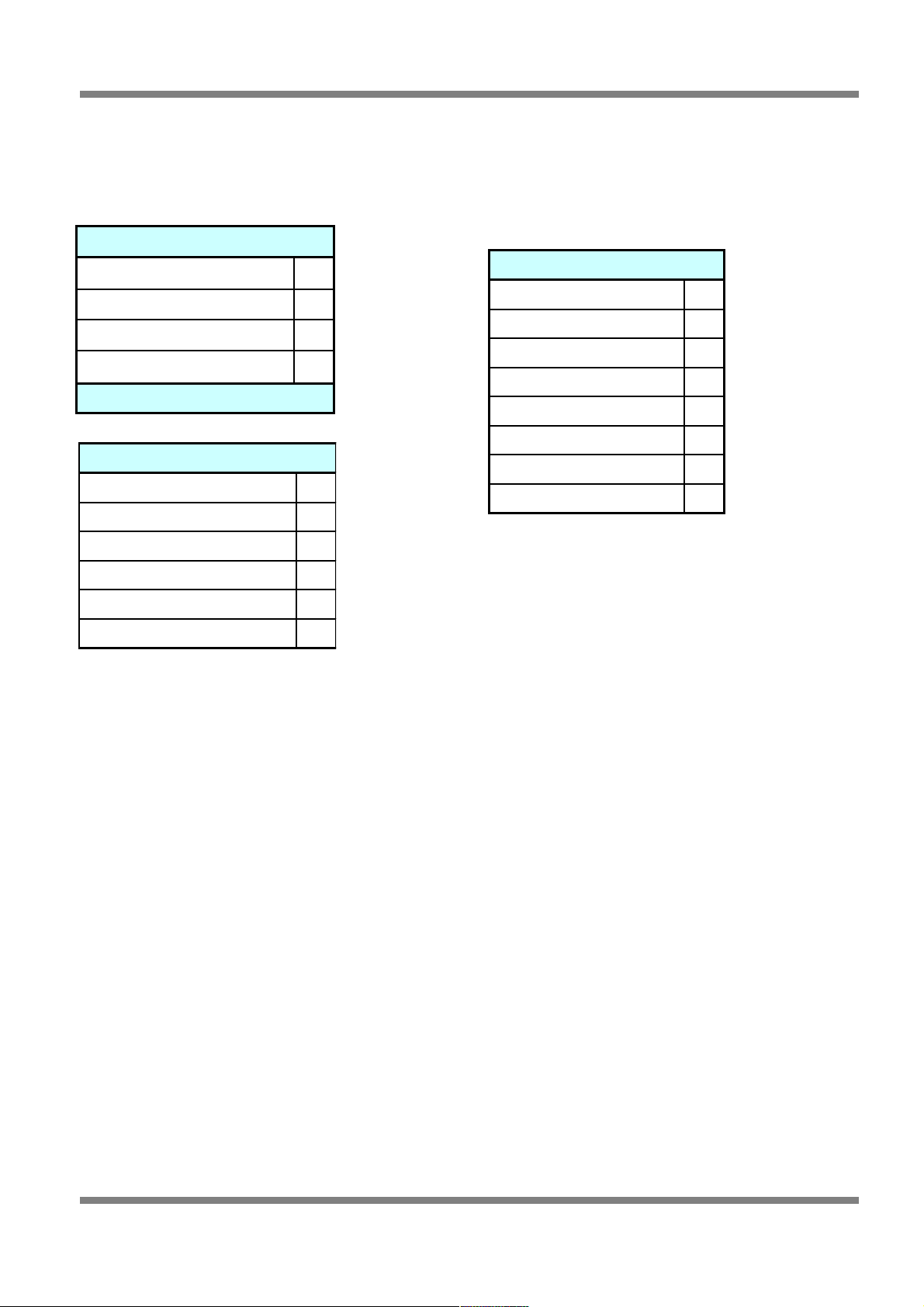
Firing Order
The firing order table is filled out with respect to cylinder number 1. Here are some examples of common
engine firing orders:
4 Cylinder 4 stroke Piston
1st Cylinder to fire 1
2nd Cylinder to fire 3
3rd Cylinder to fire 4
4th Cylinder to fire 2
8 Cylinder 4 stroke Piston
1st Cylinder to fire 1
2nd Cylinder to fire 8
3rd Cylinder to fire 4
4th Cylinder to fire 3
5th Cylinder to fire 6
6th Cylinder to fire 5
7th Cylinder to fire 7
8th Cylinder to fire 2
Firing Angles
To cater for ‘odd fire’ engines, certain triggers make use of the firing angles. To configure the firing angles,
type in the angle at which the cylinder fires with respect to cylinder number 1. This means that Cylinder 1
Angle will always be zero.
Example:
If you have an ‘even fire’ 4 cylinder engine with firing order 1-3-4-2, then the angles will be:
Cylinder 1 Angle = 0 Since the angles are with respect to cylinder 1, the definition means that
this angle must be zero.
Cylinder 3 Angle = 180 With an even fire engine, all angles between all cylinders are always
evenly spaced. Therefore, for a 4 cylinder engine will have 720/4=180
degrees between cylinder events. Since cylinder 3 is the next to fire, it will
be 180 away from cylinder 1.
Cylinder 4 Angle = 360 Cylinder 4 will fire 180 degrees after cylinder 3, therefore it fires 360
degrees after cylinder 1.
Cylinder 2 Angle = 540 Cylinder 2 fires 180 degrees after cylinder 4, therefore it fires 540 degrees
after cylinder 1.
For even fire engine applications (most engines) the cylinder firing angle does not need to be calculated
by hand, simply press the “auto generate firing angles” button on the setup page and the correct firing
angles will be generated. It is only in the case of an odd fire crankshaft that the firing angles need to be
hand generated (ie where the angle between each cylinders TDC is not constant).
Page: 28
Copyright © Haltech 2008
6 Cylinder 4 stroke Piston
1st Cylinder to fire 1
2nd Cylinder to fire 5
3rd Cylinder to fire 3
4th Cylinder to fire 6
5th Cylinder to fire 2
6th Cylinder to fire 4
Page 29
Haltech E11/E8 Instruction Manual
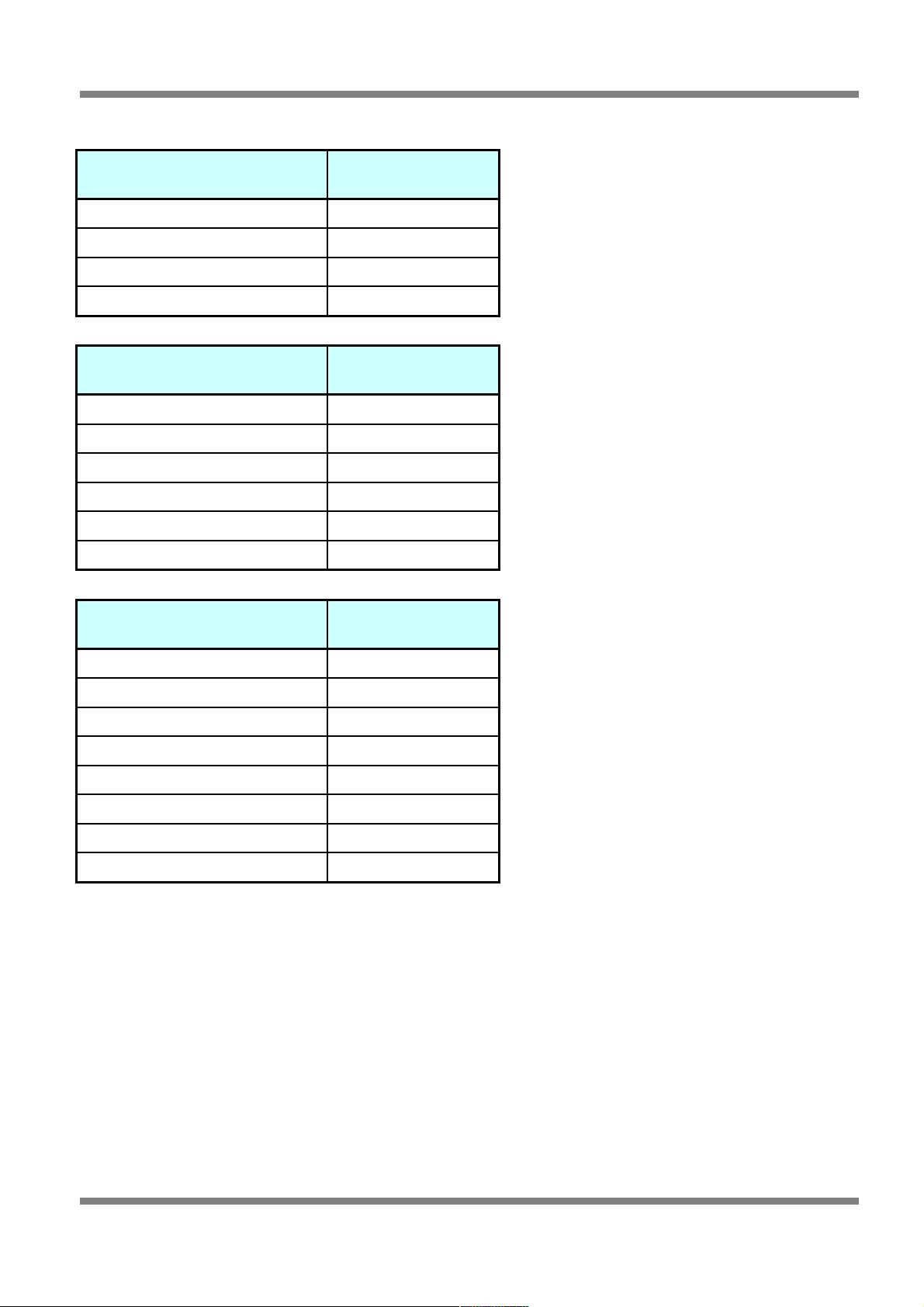
Listed below are typical cylinders angles for typical firing order, piston engines.
4 Cylinder 4 stroke Piston firing
order 1-3-4-2
Cylinder Angle
Cylinder 1 Angle 0
Cylinder 2 Angle 540
Cylinder 3 Angle 180
Cylinder 4 Angle 360
6 Cylinder 4 stroke Piston firing
order 1-5-3-6-2-4
Cylinder Angle
Cylinder 1 Angle 0
Cylinder 2 Angle 480
Cylinder 3 Angle 240
Cylinder 4 Angle 600
Cylinder 5 Angle 120
Cylinder 6 Angle 360
8 Cylinder 4 stroke Piston firing
order 1-8-4-3-6-5-7-2
Cylinder Angle
Cylinder 1 Angle 0
Cylinder 2 Angle 630
Cylinder 3 Angle 270
Cylinder 4 Angle 180
Cylinder 5 Angle 450
Cylinder 6 Angle 360
Cylinder 7 Angle 540
Cylinder 8 Angle 90
Copyright © Haltech 2008
Page: 29
Page 30
Haltech E11/E8 Instruction Manual
The Trigger and Ignition setup pages are the most Important part of any Installation!.
Getting these settings wrong or not understanding them will lead you into problems. The ECU has no idea
what is connected to it or what it supposed to see. This is why the settings must be properly set to suit the
application. The other issue is making sure the ECU can interface to the sensor(s) which different types of
signals like Hall Effect signals and Reluctor (Magnetic sensor). Interfacing to these signals may require
the use of external signal conditioners such as the Haltech RA10.
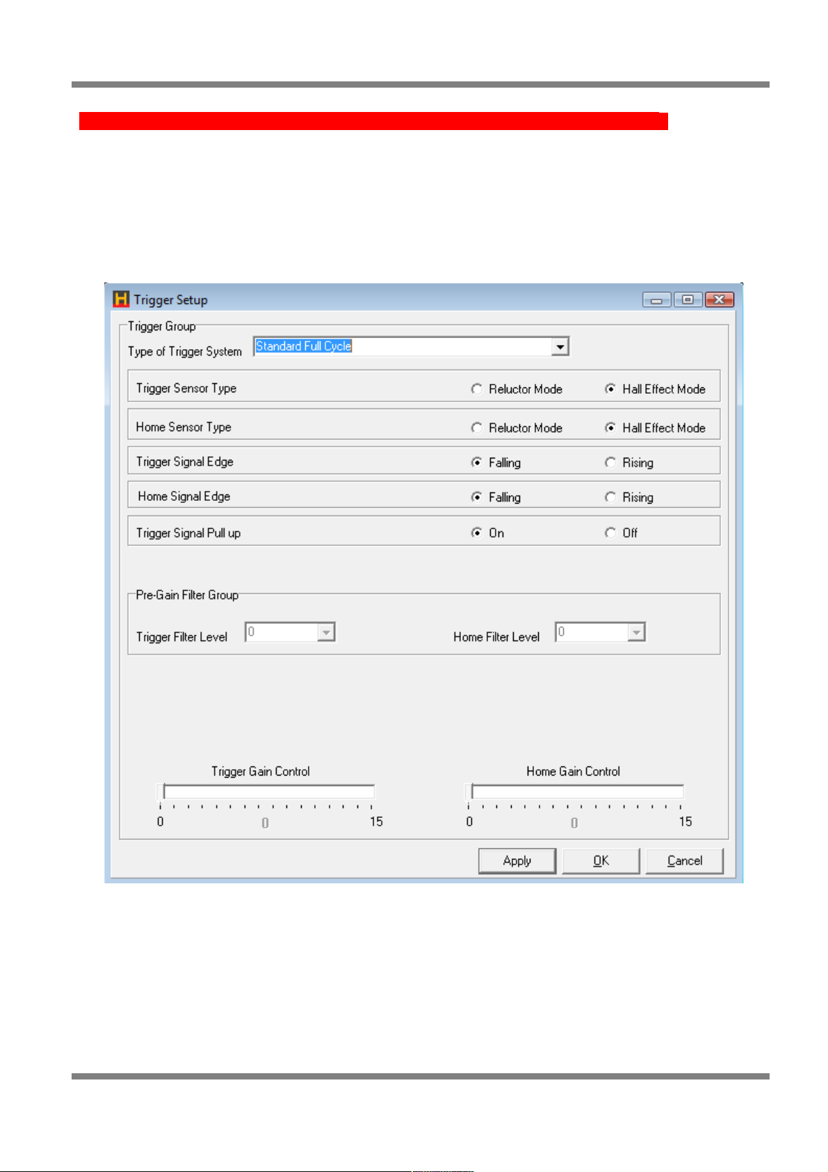
Trigger Setup
Figure 27 - Trigger Setup Screen
Trigger Group
• Type of Trigger System - Select the type of trigger that your engine uses from the options in the
drop down menu.
Page: 30
Copyright © Haltech 2008
Page 31

Haltech E11/E8 Instruction Manual
Trigger System
Type
Fuel Mode
Supported
Ignition Mode
Supported
Description
Standard No Home Multipoint
Batch
Distributor Used for engines that run a standard trigger that
provides a single pulse for each cylinders
ignition event. i.e. A standard trigger for a 8Cylinder engine will have 8 pulses, each with an
edge that is always the same angle with respect
to TDC of the next cylinder to reach TDC.
Standard Half
Cycle
Multipoint
Batch
SemiSequential
Distributor
Twin
Distributor
Waste Spark
Used for standard trigger engines that provide a
Home signal on the crank. This provides
enough information to do waste spark ignition
and semi-sequential fuel injection.
Twin distributor mode is only possible for 8
cylinder engines and 12 cylinder engines (where
supported) with this trigger.
Standard Full Cycle Multipoint
Batch
SemiSequential
Sequential
Distributor
Twin
Distributor
Waste Spark
Direct Fire
Used for standard trigger engines that provide a
Home signal on the cam (720 degrees of engine
rotation for 4-stroke engines).
Nissan Type 1 Multipoint
Batch
SemiSequential
Sequential
Distributor
Twin
Distributor
Waste Spark
Direct Fire
Nissan triggers are optical triggers with a wheel
with two tracks. One with large slots and
another with 360 small slots.
Type 1 Nissan triggers have one unique slot
and all remaining slots are the same size. The
typical slot patterns for home window teeth are
2,2,2,8 for FJ20 engines or 2,2,2,2,2,8 for RB30
engines.
Nissan Type 2 Multipoint
Batch
SemiSequential
Sequential
Distributor
Twin
Distributor
Waste Spark
Direct Fire
Type 2 Nissan triggers come with 2 unique
windows. A typical pattern is 4,8,12,8 that can
be found on most CA18 engines. Early RB
series engines use this pattern also with six
windows.
Nissan Type 3 Multipoint
Batch
SemiSequential
Sequential
Distributor
Twin
Distributor
Waste Spark
Direct Fire
Type 3 Nissan triggers come with all unique
window sizes. A typical pattern is 4,8,12,16 and
is commonly found on SR20 and late RB series
engines.
Choosing Type 1,2 or 3 will work with the ECU
with a correctly setup ‘Home Window’
parameter. However choosing the correct type
may assist in faster starting with less cranking.
Multi Tooth 24+1,
Full Sync
Multipoint
Batch
SemiSequential
Sequential
Distributor
Twin
Distributor
Waste Spark
Direct Fire
These are typically magnetic pickups with 24
teeth trigger with a single tooth home.
These are commonly found on Toyota and
Honda engines.
Multipoint
Batch
SemiSequential
Copyright © Haltech 2008
Page: 31
Page 32

Haltech E11/E8 Instruction Manual
Motronic 60-2 Distributor
Waste Spark
These are typically magnetic pickups that are
located on the crank. This style of pickup looks
as if it should have 60 evenly spaced teeth
however there are 2 teeth missing leaving only
58 teeth with a gap the width of 2 teeth at one
location.
These are commonly found on European cars
such as Audi, BMW, Porsche and Volkswagon.
Motronic 36-1 Multipoint
Batch
SemiSequential
Distributor
Waste Spark
These are commonly found on Ford engines.
Typically magnetic pickups that are located on
the crank. This style of pickup looks as if it
should have 36 evenly spaced teeth however
there is 1 tooth missing leaving only 35 teeth
with a gap the width of 1 tooth at one location.
Motronic 36-2 Multipoint
Batch
SemiSequential
Distributor
Waste Spark
These are sometimes found on Toyota engines.
Typically magnetic pickups that are located on
the crank. This style of pickup looks as if it
should have 36 evenly spaced teeth however
there are 2 teeth missing leaving only 34 teeth
with a gap the width of 2 teeth at one location.
Motronic 60-2 +
Cam home
Multipoint
Batch
SemiSequential
Sequential
Distributor
Waste Spark
Direct Fire
With the addition of the Home signal on the
cam, this trigger enables the support of full
sequential injection and direct fire multi-coil
ignition.
These are commonly found on European cars
such as Audi, BMW, Porsche and Volkswagon.
Motronic 36-1 +
Cam home
Multipoint
Batch
SemiSequential
Sequential
Distributor
Waste Spark
Direct Fire
With the addition of the Home signal on the
cam, this trigger enables the support of full
sequential injection and direct fire multi-coil
ignition.
These are commonly found on Ford engines.
Motronic 36-2 +
Cam home
Multipoint
Batch
SemiSequential
Sequential
Distributor
Waste Spark
Direct Fire
With the addition of the Home signal on the
cam, this trigger enables the support of full
sequential injection and direct fire multi-coil
ignition.
These are sometimes found on Toyota engines.
Subaru Multipoint
Batch
Semisequential
Sequential
Distributor
Twin
Distributor
Waste Spark
Direct fire
coils
For Subaru 4 cylinder EJ series engines.
Distributor
Page: 32
Copyright © Haltech 2008
Page 33

Haltech E11/E8 Instruction Manual
Subaru MY01
Multipoint
Batch
Semisequential
Sequential
Twin
Distributor
Waste Spark
Direct fire
coils
For Subaru 4 cylinder EJ20 series engines in
2001 and later WRX and Forrester GT.
Rotary Triggers Fuel Mode
Supported
Ignition Mode
Supported
Description
2 or 3 pulse Trig
Rotary
Multipoint
Batch
Sequential
Distributor
(with toggle)
Waste Spark
Direct Fire
For rotary engines that have standard trigger
style trigger adapted to them.
2 or 3 pulse Trig
Rotary No Home
Multipoint
Batch
Distributor For rotary engines that have standard trigger
style trigger adapted to them and no Home
Signal.
Multi Tooth Rotary Multipoint
Batch
Sequential
Distributor
(with toggle)
Waste Spark
Direct Fire
The factory trigger for a Mazda rotary engine will
be a 24 tooth magnetic trigger with a Home
signal for every rotation of the crank.
Figure 28 - Trigger Type Options
• Trigger Sensor Type - If your Trigger Input Signal is a magnetic pickup type, then you will need to
use the internal reluctor by setting ‘Reluctor Mode’. Otherwise, if you have a Hall effect sensor type
that produces a digital square wave output, then select ‘Hall Effect Mode’. Optical triggers also
produce a square wave output and the input type should also be ‘Hall Effect Mode’. Generally a
“hall effect” trigger type will require power and ground, a reluctor style sensor does not require
power.
• Home Sensor Type - If your Home Input Signal is a magnetic pickup type, then you will need to
use the internal reluctor by setting ‘Reluctor Mode’. Otherwise, if you have a Hall effect sensor type
that produces a digital square wave output, then select ‘Hall Effect Mode’. Optical triggers also
produce a square wave output and the input type should also be ‘Hall Effect Mode’.
• Trigger Signal Edge - The trigger signal from a crank or cam angle sensor will always be
converted to a square wave signal. As a square wave, there will always be a rising and falling edge
to every pulse received. Depending on the sensor, one of the edges may move with respect to the
actual crank position as engine RPM changes. Set this parameter to select the edge that does not
move with respect to the crank at all engine speeds. Set this edge to ‘Rising’ when using the
internal reluctor as a starting point.
• Home Signal Edge - Similarly with the home signal, one of the edges associated with this signal
will have a fixed position with respect to the crank position, while the other edge may move slightly
with RPM. Choose the edge that does not move with respect to the crank position when RPM is
changed. Set this edge to ‘Rising’ when using the internal reluctor as a starting point.
• Trigger Signal Pull Up - By default, this option should be left in the ‘On’ state. When using Hall
effect input triggers from certain factory trigger systems however, it is sometimes required to turn
this option ‘Off’. Leave this feature in its default state unless you are sure that this needs to be
turned off.
Copyright © Haltech 2008
Page: 33
Page 34

Haltech E11/E8 Instruction Manual
• The Following Filter and Gain settings are only available in Reluctor Mode
The ECU needs to see a clean Trigger signal before it can start controlling the engine. If you are
having problems you have the option of adjusting the signal quality. In cases where the signal is
too weak and or not enough signal strength, you can use the Gain settings to boost the signal. In
some cases a high Gain setting may amplify noise, the same applies to the Filter Level adjustment
if there is interference from Spark Noise the Filter Level may need to be used, ( too high value
may cause problems at high RPM). Experiment until you get a stable RPM reading and check the
readings from Trigger Diagnostic Data Page (Under Data Pages Menu).
Typical triggering symptoms are… if a Home signal has false triggered, it will cause
synchronising problems and loose track of the start of the Engine cycle, a missing Trigger signal
may loose count of which cylinder is to fire next. The end result can lead to a engine misfiring,
running rough, backfiring hard to start or not starting at all.
If you cannot get satisfactory results with the Filter/Trigger settings, contact your Haltech
dealer and enquire about an external Reluctor Adaptor.
• Trigger Filter Level – This filter setting allows you to clean up the Trigger signal before its
processed by the ECU. You have the option of selecting a number from 0 to 2, 0 = no filter, 1 = low
filter, 2 = high filter.
• Home Filter Level – This filter setting allows you to clean up the Home signal before its processed
by the ECU. You have the option of selecting a number from 0 to 2, 0 = no filter, 1 = low filter, 2 =
high filter.
• Trigger Gain Control – This Gain setting allows you to amplify the Trigger signal, the gain of the
input stage to this reluctor can be set using this slider control. Start with low values and gradually
increase the gain until you get a steady trigger signal throughout the rev range that you intend to
operate your engine.
• Home Gain Control - When the internal reluctor adaptor is used to process the Home Input signal,
the gain of the input stage to this reluctor can be set using this slider control. Start with low values
and gradually increase the gain until you get a steady Home signal throughout the rev range that
you intend to operate your engine. An unsteady Home Signal can lead to drastic changes in timing
on multi-tooth triggers so check this with a timing light with Ignition Timing Lock turned on while
you rev the engine.
Page: 34
Copyright © Haltech 2008
Page 35

Haltech E11/E8 Instruction Manual
Ignition Setup
Figure 29 - Ignition Setup Page
Timing Group
• Lock Timing - When this setting is checked, the ignition advance is fixed to the value described in
Lock Degrees BTDC.
• Lock Degrees BTDC - The ignition advance angle used when Lock Timing is enabled.
• Trigger Angle BTDC - This is the angle between the trigger input and the corresponding piston’s
(or rotor’s) TDC. For multi-tooth triggers such as those found on Toyota’s, Honda’s and Mazda’s,
the trigger point is the tooth defined by the Tooth Offset that is described below. The trigger angle
must be between the largest intended advance angle and the angle between trigger events.
E.g. If the largest ignition advance angle you wanted to use was 32 degrees on a 4 cylinder engine, then
your trigger angle must be between 32 to 180 degrees. Angle between triggers for a 4 cylinder is 720/4 =
180 degrees. For more information on how to set the tooth offset and trigger angle correctly please refer to
the quickstart guide you received with your ECU.
• Tooth Offset - The tooth offset is the number of teeth from the Home signal to the tooth that is
chosen to be the trigger tooth. The trigger tooth should be chosen so that the trigger angle can be
dialled into the range described below. If this field is grey and not able to be changed, then ignore
this parameter, as it does not apply for the given trigger.
Setting the Base Timing
Copyright © Haltech 2008
Page: 35
Note: Setting the base timing correctly is the most imporatant step in getting the Haltech
ECU to operate correctly. If the base timing is not set correctly none of the software
settings will be correct. This is the most important step in the setup procedure.
Page 36

Haltech E11/E8 Instruction Manual
Tooth Offset and Trigger Angle Relationship
Tooth offset and trigger angle are closely related and are best explained visually so see below for a visual
representation off the tooth offset.
The tooth offset is the number of teeth between the home event and the tooth that is chosen to be the
trigger tooth. In the example above the home event is the missing tooth.
The trigger angle is the angle between the trigger tooth and TDC therefore the tooth offset plus the trigger
angle equals the angle between the home event and TDC.
As can be seen above the trigger angle is simply the angle before top dead centre (TDC) at which the
trigger event occurs (when the tooth selected to be the trigger tooth passes by the sensor). In the case of
a multi tooth trigger without a missing tooth (such as a Toyota 24 trigger) the home home event comes
from a separate single tooth sensor usually located on the camshaft.
When using a custom trigger of any sort the sensor must produce at least one trigger event for each
ignition event and each trigger must occur a constant angle BTDC (in other words the teeth must all be
evenly spaced and the number of teeth an even multiple of the number of cylinders the engine has).
The trigger angle value must be greater than the maximum advance you wish to run, so if the maximum
advance you wish to run is 40 deg, the Trigger Angle value needs to be at least 40 deg (its wise to have at
least 10 degrees margin). If the Trigger Angle value is set too low, the ignition timing will not be able to
achieve the full advance set in the ignition map/s.
By selecting the correct trigger tooth in the tooth offset field this should always be possible.
Setting the tooth offset and trigger angle on an engine where the location of the crankshaft position sensor
and camshaft position sensor is unknown is very easy and requires only a timing light. The following
procedures outlines how to achieve this:
Go to the fuel setup page and disable the fuel injectors (at this stage it is not desired that the engine
attempts to start), to reduce stress on started motor it is also advisable to remove the spark plugs to help
the engine crank more freely when setting base timing (be careful when doing this as spark from ignition
coils have been known to cause severe injury and even death on some occasions).
Page: 36
Copyright © Haltech 2008
Figure 30: Trigger Angle and Tooth Offset Visually Outlined
Page 37

Haltech E11/E8 Instruction Manual
Set lock timing to ON and lock timing angle to 10 degrees. Crank engine, using a timing light connected to
ignition lead for number 1 cylinder adjust the tooth offset and trigger angle until timing reads 10 degrees
as viewed with a timing light on crank pulley. Tooth offset gives large changes to timing, trigger angle is
used to fine tune timing to exactly 10 degrees (any angle can be used as the lock timing angle. In this
example 10 degrees was used. It is however possible to set the lock timing to zero degrees (or any other
positive number) and adjust tooth offset and trigger angle until the crank pulley shows this value when
viewed with a timing light).
• Nissan Home Window - Nissan trigger requires the detection of a particular sized window to
establish the ‘Home’ position of the engine. Some Nissan triggers have several uniquely sized
windows that can be used for this purpose. This parameter selects which of the unique windows to
use. If this field is grey and not able to be changed, then ignore this parameter, as it does not apply
for the given trigger.
• Constant Charge Time - The time used to charge the ignition coils when Constant Charge mode
is selected. See Appendix D for more details on ignition systems.
• Spark Break Time - This is the minimum time between when the spark edge occurs and the next
charging edge is allowed to occur. This time will depend on how quickly the coil can discharge to
fire the spark. This threshold is only used when charging time is limited. This is only applicable in
Constant Charge Mode. The default value is 600 µs.
Copyright © Haltech 2008
Page: 37
Figure 31: Ignition Setup Page
Page 38

Haltech E11/E8 Instruction Manual
Ignition Mode Group
• Spark Mode - This mode must be set to the type of ignition system that is to be used on the
engine.
For Piston Engines
Trigger Injection Mode
Standard Trigger Full Cycle, with home on the CAM
24 +1 Multi-Tooth trigger (Honda, Toyota)
Nissan Trigger
Motronic with home signal on the CAM
Subaru
Subaru MY01
Direct Fire Multi Coil
Standard Trigger Full
Standard Trigger Half Cycle with home on the crank
24 +1 Multi-Tooth trigger (Honda, Toyota)
Nissan Trigger
Motronic
Subaru
Subaru MY01
Waste-Spark
All triggers Distributor
For Rotary Engines
Trigger Injection Mode
Standard Trigger with crank home
24 +2 Multi-Tooth trigger
Direct Fire
Wasted Spark Leading ignition
Distributor (with toggle)
Standard Trigger with no home Distributor (without toggle)
Figure 32 - Ignition Trigger Modes
Ignition Spark Edge
The ignition spark edge determines the polarity of the waveform used to drive the ignition module. Falling
edge ignition will use a zero voltage output at idle, a +12V signal for charging, and a falling edge to zero
volts to fire the spark. Most factory ignition systems use falling edge. This is the default setting.
Figure 33 - Ignition Spark Edge Falling
Page: 38
Copyright © Haltech 2008
Note: Take care when setting the ignition spark edge, incorrect settings will damage the
ignition system.
Waveform
Naturally Low
Time
Voltage
+12V
Signal Rises to
12V to Charge
Coils
Page 39

Haltech E11/E8 Instruction Manual
Rising Edge Triggered - Some Honda and CDI style ignition modules are known to be rising edge
triggered. These modules expect to see a naturally high signal. When the voltage falls to 0V, the module
charges the coil. When the voltage returns to 12V, the spark is fired.
Figure 34 - Ignition Spark Edge Rising
Trailing Spark Edge
This parameter is only available when in rotary mode. This parameter is the same as Ignition Spark Edge,
but applies only to the trailing spark. The leading spark for a rotary engine is setup with Ignition Spark
Edge. This feature allows for different ignition systems to be used on the leading and trailing coils.
Dwell Mode
This mode must be set to the type of ignition module that it to be used on the engine, almost every ignition
system that comes from a modern vehicle (i.e. an engine that has EFI as standard) uses constant a
constant charge ignition system.
Trailing Dwell Mode
This parameter is only available when in rotary mode. This parameter is the same as Dwell Mode, but
applies only to the trailing spark. The leading spark for a rotary engine is setup with Dwell Mode. This
feature allows for different ignition systems to be used on the leading and trailing coils.
Ignition Map Selection
This selects which map to use. If an external input is used to select the map, then this setting is ignored.
Ignition Trims
Allows ignition to br trimmed either as an overall trim, or as an individual cylinder trim.
Zero Throttle Map Enable
Allows for a seperate ignition map to be enabled when the engine's throttle is closed.
Copyright © Haltech 2008
Page: 39
Waveform
Voltage
+12V
GND
Ignition Signal Pulls
to Ground to Charge
Coils
Naturally High
Note: Take care when setting the ignition spark edge, incorrect settings will damage the
ignition system.
Page 40

Haltech E11/E8 Instruction Manual
Fuel Setup
Figure 35 - Fuel Setup Page
Decel Cut Parameter Group
Deceleration cut is a feature that stops the fuel injectors from injecting fuel when the throttle position is
zero and the engine speed is above the Decel Cut RPM. To ensure that the transition to fuel cut is
smooth, the ignition timing is retarded slightly before the fuel is cut. Likewise, when the fuel is restored,
the injectors resume normal injection and the ignition timing advances back to normal.
• Decel Cut Enable - This check box enables deceleration fuel cut. This feature is primarily used to
save fuel when on a deceleration condition.
• Decel Cut RPM - Fuel is not cut when the engine speed falls below this RPM. Set this RPM to be
above your idle RPM otherwise your engine will stall at idle.
• Decel Cut Temp - Fuel is not cut when the coolant temperature is below this temperature value.
This is useful for cars with an idle up mechanism based on coolant temp that sets the idle speed
above the RPM used for decel fuel cut. This is common in early EFI vehicles with ‘wax pellet’ style
cold idle up.
Page: 40
Copyright © Haltech 2008
Page 41

Haltech E11/E8 Instruction Manual
• Decel Cut Delay - This is the time in seconds that the ECU will wait before starting the decel cut
phase, after seeing a zero throttle condition. This delay stops any unwanted fuel cutting or ignition
changes between gear changes or momentary zero throttle conditions.
• Max Decel Cut Retard - The amount of ignition retard used to smooth the transitions to fuel cut.
• Decel Cut Enrich - Upon restore of deceleration cut, the intake manifold walls will be completely
dry. This enrichment factor will eliminate any lean conditions upon fuel being restored.
The following example assumes a constant load so that injection times and advance does not vary. Of
course this is not realistic since load will change with movements in TPS. The example aims to simply
demonstrate the timing interaction of fuel and ignition in the event of a deceleration cut condition.
Figure 36 - Decel Cut Cut Illustrated
Maps Group
• WOT Map Enrich - Click on the check box to enable the use of the WOT map. When the throttle
position exceeds the WOT value. When the WOT map is used and the WOT condition is met, the
injection values are taken from this map and the base fuel map values are ignored.
• Zero Throttle Map Enable - Similar to the WOT map described above, but for a zero throttle
condition. This can help some cars achieve a stable idle.
• Fuel Map Select - This selects which map to use. If an external input is used to select the map,
then this setting is ignored.
Throttle Pumps
Throttle pumps aid in improving engine response when the throttle on a conventional fuel injected vehicle
is opened rapidly. The throttle pumps work by adding additional injection pulses (asynchronous
enrichment) and enriching the current fuelling pulses (synchronous enrichment) when it sees a change in
throttle position. The throttle pump setup allows the tuning of:
* How much enrichment is needed for a given RPM, throttle position and TPS rate of change.
* The biasing of the enrichment between asynchronous and synchronous types according to a given RPM.
* The speed at which the synchronous enrichment decays.
Copyright © Haltech 2008
Page: 41
TPS
Ignition Advance
Injection
Time
Injection
Time
Advance
TPS %
Decel
Cut
Decel
Cut
Restore
ignition
Page 42

Haltech E11/E8 Instruction Manual
Note the rate of change of throttle position is how far the throttle moves over a 10ms time frame. A fast
throttle movement could have a TPS rate of change of 15% this means that in a time frame of 10ms the
throttle position moved 15%. A slow throttle movement could have a TPS rate of change of 1%, which
means that in a time frame of 10ms the throttle position only moved 1%.
Figure 37 – Throttle Pump Setup Screen
Throttle Pump Settings:
• Max Asynchronous Pulses This is the maximum number of extra injector pulses that can happen
per injector output during an enrichment event.
Range: 0 – 10 pulses.
Default: 5.
• Throttle Deadband A rate of change of throttle position greater than this value will trigger an
enrichment event.
Range: 0.0 – 10.0 %.
Default: 0.5 %.
• Delay Between Enrich Events The minimum time between asynchronous enrichment
events. This is to stop excess fuelling when constantly pumping the throttle.
Range: 0.00 – 2.00 sec.
Default: 0.80 sec.
Page: 42
Copyright © Haltech 2008
Page 43

Haltech E11/E8 Instruction Manual
• Overall Trim The trim value scales the fuel enrichment. 0% makes no changes to the fuel
enrichment. 100% will add an extra 100% fuel to the enrichment.
Range: 0.0 – 300.0 %.
Default: 100.0 %.
Throttle Pump Maps
Enrichment Sensitivity Map
This map allows for the tuning of the amount of enrichment needed according to a given RPM and
throttle position. In general more enrichment is needed at a low throttle position because a change will
cause a larger in rush of air than at a higher throttle position. At a low RPM more enrichment is needed
because of low air speeds and the atomisation of fuel is poor. This becomes less of a problem as the
engine goes up in RPM and airflow increases. The value in this map represents the enrichment needed at
the maximum TPS rate of change. This map is the first to be tuned but also make sure that the right hand
side of the TPS Rate Of Change Sensitivity Map equates to the maximum TPS rate of change
achievable with a sensitivity value of 100%.
TPS Rate Of Change Sensitivity Map
With the Enrichment Sensitivity Map tuned for a maximum TPS rate of change slower throttle
movements can be scaled accordingly with the TPS Rate Of Change Sensitivity Map. The right hand
side of the map should contain the maximum TPS Rate of change in its axis value and 100% in its map
value. For slower throttle movements (lower TPS rate of change values) a smaller percentage value can
be put in the map.
Percentage Asynchronous Enrichment Map
This map determines what percentage of the fuel enrichment goes to the asynchronous type of
enrichment. 0% in the map means that all of the fuel enrichment will be delivered synchronously (ie no
additional fuel pulses will be added, the entire throttle pump enricment will solely by extending the normal
injection pulse). 100% in the maps means that all of the fuel enrichment will be delivered asynchronously
(ie the normal injection pulse remains the same and all the enrichment fuel is added through extra pulses
following the main injection pulse (these are called the asynchronous pulses)). Note that if the enrichment
value exceeds 9.5ms (the maximum size of an asynchronous pulse) the rest will be delivered
synchronously. In General at a low RPM, when the injection events are further apart, the asynchronous
fuel enrichment helps deliver the extra fuel over a longer period. At a high RPM asynchronous enrichment
is not needed because regular injection events are more frequent.
Synchronous Enrichment Decay Map
This map determines how fast the synchronous enrichment (ie the enrichment added by extending
the normal injection pulse) decays back to zero (no additional enrichment). The units entered in are
milliseconds per engine cycle. E.g. a value of 0.5 will mean that the enrichment will decay 0.5ms every
engine cycle. The bigger the value the faster it will decay.
Coolant Correction Map
This map applies a correction factor to the fuel enrichment based on the coolant temperature. E.g.
100% gives 100% extra fuel enrichment.
Shortcut Keys For Mini Maps
• Page Up Increments map value.
• Page Down Decrements map value.
• L Used to linearise between two points.
• V Used to change the value in a cell or multiple selected cells.
Other : Ctrl T Opens throttle pump setup page without having to open fuel setup.
Copyright © Haltech 2008
Page: 43
Page 44

Haltech E11/E8 Instruction Manual
Throttle Pump Map Enable - Click on this check box to enable throttle pumps enrichment.
• Injectors Enable - Click on this check box to enable the injectors. This feature is often used when
setting up ignition timing.
• Injector Current Setup – Haltech ECUs have intelligent injector control circuitry that allows for
many different makes and models of injectors to be run without the need for resistor packs. For this
circuitry to control each injector correctly the ECU must have the injector current control
programmed by the user for the injectors being used. To determine how much current each injector
requires it is very simple. Current can be calculated using Ohms Law (V = I / R), in an automotive
electrical system the supply voltage is assumed at 12V. Using Ohms law R is simply the resistance
of the injector. So to determine the peak current required for an injector simply take 12 divide by
Injector Resistance (measure injector resistance between the two electrical connectors on the
injector). For example, an injector with 4 Ohm resistance has a peak injector current draw of
12 / 4 = 3 Amps
Figure 38 – Injector Current Control Setup Screen
• Injection Mode - Choose the mode of injection to run for your engine.
• Sequential mode - Is the preferred mode wherever possible, which fires each injector
individually in reference to the intake valve opening time, a crankshaft reference signal is
required. Injection timing is tuned using the end of injection map found in the fuel maps menu.
• Semi-Sequential - fires half the required fuel on the intake stroke and the remaining half on
the opposing half of the stroke. This is the preferred mode when only a crank signal reference
is available (ie no camshaft signal is required).
• Batch mode - Injection fires the injectors in two even groups. This is aimed at reducing fuel
rail pressure fluctuations. This mode of injection does not require any home (camshaft) signal
to operate. The angle of injection is not defined, and the injection angle map is not used. The
frequency of injection is defined by the Ignition Divide By parameter. Batch mode is not to be
used on engines with odd numbers of cylinders or 6 cylinder engines. Ignition divide by should
be set to number of cylinders / 4.
Page: 44
Copyright © Haltech 2008
Page 45

Haltech E11/E8 Instruction Manual
• Multipoint mode - Injection is the most basic form of injection that fires all injectors
simultaneously. This mode of injection does not require any home or reference signal to
operate. The angle of injection is not defined, and the injection angle map is not used. The
frequency of injection is defined by the Ignition Divide By parameter.
For Piston Engines
Trigger Injection Mode
Standard Trigger Full Cycle, with home on the CAM
24 +1 Multi-Tooth trigger (Honda, Toyota)
Nissan Trigger
Motronic with home signal on the CAM
Subaru
Subaru MY01
Sequential
Standard Trigger Full Cycle, with home on the CAM
Standard Trigger Half Cycle, with home on the crank
24 +1 Multi-Tooth trigger (Honda, Toyota)
Nissan Trigger
Motronic
Subaru
Subaru MY01
Semi-Sequential
Standard Trigger
24 +1 Multi-Tooth trigger (Honda, Toyota)
Nissan Trigger
Subaru
Subaru MY01
Batch
All triggers Multipoint
For Rotary Engines
Trigger Injection Mode
Standard Trigger with crank home
24 +2 Multi-Tooth trigger
Sequential
Standard Trigger with no home Multipoint
• Ignition Divide By - This parameter is only used in batch and multipoint injection modes. The
value of ignition divide by will determine the number of injections per engine cycle. E.g. If the
engine is a 4 stroke 4 cylinder, then an ignition divide by of 2 will enable 1 injection for every 2
ignition events. This is the equivalent of one injection per crank rev. If you are unsure what to set
this to, then leave the value set to the default of half the number of cylinders.
Copyright © Haltech 2008
Page: 45
Page 46

Haltech E11/E8 Instruction Manual
The following table is a recommended setting for Ignition Divide By values for various fuel injection
modes and typical piston engines.
Number of
Cylinders
Mode of Injection Ignition Divide By Injections per rev (per
cylinder)
4 Multipoint
2
1
6 Multipoint
3
1
8 Multipoint
4
1
4 Batch
1
1
6 Batch
NA
NA*
8 Batch
2
1
*Note: 6 cylinder batch injection is not suggested.
• Fuel Scale factor - The Fuel Scale Factor is the overall scaling factor for the fuel injection times.
The allowable range is from 0% to 220%. A value of 100 is typical.
• Injection Angle - When sequential or semi-sequential injection is selected, the angle of injection
with respect to the combustion process can be programmed (fuel correction maps - end of injection
map). The angle in the maps can be used to determine when the start angle of an injection pulse,
or the angle at which the injection pulse will finish. By default, leave this set to End of Injection.
• Staged Injection Setup - See section Staged Injection for more details on how to setup staged
injection.
• Injector Trims - Injector trims allows you to adjust the fuel delivery between each individual
injector to account for any minor differences between injectors or fuel rail design. The trims allow a
maximum of ±12.5% of injection time.
• Closed Loop Oxygen Sensor - Closed loop O2 control is used to improve economy, reduce
emissions and assist catalytic converter operation if you vehicle has one fitted. See section in the
tuning guide for more information on tuning the O2 parameters.
Over Boost Cut Out
• Enable - Click on this check box to enable over boost cut off. This is only applicable to forced
induction vehicles.
• Over Boost Cut - Fuel is cut when this boost pressure is reached.
• Over Boost Restore - Fuel is restored when the boost level falls back to this safe level. This value
must be set to the less than the Over Boost Cut value.
Fuel Pump Settings
• Invert Fuel Pump Output - Click on this check box to invert the output of the fuel pump control
wire, when this option is selected the fuel pump control output will be at ground when the pump is
not running and open circuit to run the pump. Rarely is this setting used.
• Fuel Pump Prime – Sets the time period the fuel pump primes for when the ignition first switched
to the on position.
Page: 46
Copyright © Haltech 2008
Page 47

Haltech E11/E8 Instruction Manual
Sensor Setup
The Haltech Halwin software allows the user to calibrate sensor inputs to their own calibration, this is
useful when using a vehicles OEM sensors or when haltech sensors cannot be used for some other
reason.
Calibrating The Throttle
The throttle sensor must be calibrated so that the ECU knows the start and stop positions of the sensor.
Always calibrate the throttle even if a map is supplied as the throttle calibration can vary between even
identical models of cars.
Before you begin, ensure that the closed throttle position is in a position that you wish to leave it in. If you
change the closed throttle position, re-calibrate your throttle. Usually, the throttle is set to ensure a slow
idle when the throttle is closed. If the required opening for idle is not known, make an estimate but keep in
mind that this may be the reason for poor idle later on, and further adjustment may be needed. Choose
the "calibrate throttle" option from the options menu and follow the instructions on the screen.
Figure 39 - Throttle Position Sensor Calibration
The calibration process begins by pressing the Set button as shown in Figure 39 above.
The dialog will ask you to set the minimum throttle opening. It is a good idea to give the throttle a quick
press to see if it returns to the same position consistently without sticking. After you are happy that the
throttle is returning consistently to the same zero position, press the Set button once more.
The dialog will then ask you to hold the throttle at full throttle. Whilst holding the throttle all the way down,
press the Set button again on the dialog.
If the calibration process was smooth, commit the new calibration to the ECU by pressing the OK button.
Sensor Filtering
Allows for the TPS and MAP sensor inputs to be filtered. This can help on applications where there is
severe noise in the electrical system causing the TPS or MAP sensor to become unstable. If this occurs
throttle pumps can be falsely triggered causing the engine to run poorly.
The lower the number in the filter level the less filtering that is applied, the higher the number the more
filtering applied.
Figure 40 - Sensor Input Filtering
Copyright © Haltech 2008
Page: 47
Page 48

Haltech E11/E8 Instruction Manual
Program Setup
Program Setup allows the Halwin software to be customised for your preferences. No settings in this
dialog affect the operation of the vehicle. Currently, program setup allows the selection of which serial
communications port to use and for selection of Imperial and Metric units.
Configuration Text
The tuning of a map is dependent upon many factors that are outside the control of the ECU. In order to
ensure that the map will suit a certain vehicle, these items must be checked manually. To assist in
keeping track of the conditions under which the map was tuned, the Configuration Text allows some
description of the engine and vehicle.
The text that is entered in this dialog is entirely optional, but it is highly recommended that this text be filled
out as completely as possible to assist yourself and others when the map is next opened.
Figure 41 - Engine Configuration Text Page
Page: 48
Copyright © Haltech 2008
Page 49

Haltech E11/E8 Instruction Manual
Options Menu
Firmware Update
This option should not be used unless you are instructed to update your firmware to fix a problem, or you
have purchased an upgrade that required firmware to be updated. Under no circumstances should
firmware be updated to a more recent firmware just for the sake of using the latest firmware.
Updating your ECU’s firmware
Turn on your ECU, but do not start your engine. Start your laptop with Halwin software and go online.
Check your firmware version and note the version information.
Figure 42 - Firmware Version Information
Before going any further, save the map that is currently in the ECU, this map will later be re-loaded into
the ECU after the update is complete.
Select the Firmware Update option. After you have selected the Firmware Update option, you will be
presented with the following dialog window:
Figure 43 - Firmware Update
Click on the button to the right of the filename to select the binary firmware file (this file will have a .bin file
extension) that you will use to update your ECU.
Make sure that your engine is not running. After the correct file appears in the ‘Firmware File’ field, press
the Next button. The ECU will reboot before Halwin begins to write to the ECU. As the firmware is being
written, a status message will inform you of what percentage of firmware writing is complete.
Copyright © Haltech 2008
Page: 49
Warning: Before updating firmware, ensure that the ECU is turned on, but
the engine is not running. The outputs from the ECU should change to a
non-connected safe state , however, it is good practice to unplug the 34
pin connector on your ECU before beginning a firmware update operation.
Page 50

Haltech E11/E8 Instruction Manual
Figure 44 - Firmware Update 46% Complete
When the status reaches, 100% wait for the dialog to present an OK button. Press OK to complete the
firmware update. You should now reset your ECU by turning the ignition off then back on. The new
firmware should now be loaded into the ECU. The process is not yet finished.
Check your firmware information again to ensure that the firmware has indeed been updated to the correct
version.
In most circumstances where the firmware is updated the software should also be updated (see Installing
Halwin guide earlier in this chapter for more information on installing Halwin). It is essential that the
firmware being used is being used with the software it was designed for.
Once the firmware has been updated within the ECU and the new version of Halwin loaded onto the
laptop used for tuning the default map from the new software must be loaded into the ECU. This step
enables the new features that the firmware update contains.
Once the default map from the new version of Halwin has been loaded the map that was orginally in the
ECU (this is the map that was saved at the beginning of the firmware update procedure) can be loaded
back into the ECU. A quick summary off this procedure is as follows:
1. Save the current map in the ECU with previous version of Halwin.
2. Install the new version of software Halwin (e.g. Halwin_1.89).
3. Disconnect the 34pin connector of the ECU, or disconnect the ignition modules.
4. Open the new version of Halwin (e.g. Halwin_1.89).
5. Load in the new firmware (E11s2v11B35_H185.BIN).
6. Load in the new default map (default.map).
7. (Located at C:\Program files\Haltech\HalwinV1.89\default.map) (use “defult_e8.map for E8 ECU's)
8. Now load in your previously saved map, from the older version of Halwin into the ECU.
If the firmware update fails, cancel the current firmware update. After cancelling successfully, shut down
the Halwin software and turn off your ECU.
Turn on the ECU, restart the Halwin software and go online. The ECU is now in “boot-mode”, while in this
mode it will not run the engine. To get out of boot-mode attempt to update the firmware once again.
Page: 50
Copyright © Haltech 2008
Page 51

Haltech E11/E8 Instruction Manual
If the firmware update continues to fail please contact your Haltech dealer.
Firmware Version Information
In order to assist in supporting our product, the firmware information may be necessary in order to
diagnose any support issues that may arise. In addition to this purpose, the firmware information is also a
useful way to verify that a firmware update operation has been successfully performed.
Figure 45 - Firmware Version Information
The convention for version numbers is as follows:
Series Number - This number will be incremented when a significant change to the product is made. Any
changes to the map structure or format will result in a new series of firmware.
Version Number - This number will be incremented when a new feature is added or improvement is made
to the firmware.
Variant Number - The variant number is used to distinguish mainstream firmware from specialised
firmware used for special applications. Variant 1 is the normal variant number for general release
firmware. Factory boot mode firmware has the variant number of zero.
Build Number - This number is incremented whenever a version of firmware is released. An increase in
build number indicates a bug fix or minor revision to the operation of the ECU.
Stepper Motor Control
• Idle Control - This section refers only to 4 wire stepper motor idle control. For this meathod of idle
control the 2 wires labelled IDLE 1 – IDLE 4 are to be used. These wires can only be used to
control a 4 wire stepper motor style idle speed controller. An idle speed controller with only 2 or 3
wires is a solenoid valve and programmed as a BAC (bypass air control) valve using PWM signals,
this method of idle control is described in the Auxiliary Output Setup section . Refer to the tuning
guide section for a description of how to program both types of idle speed controller.
• Oil Metering Pump Control - Some rotary engines have an oil pump for lubrication that can be
controlled electronically to vary the amount of oil injected into the engine. If your rotary engine has
this feature, enable this option. The Feedback Min and Feedback Max values should not need to
change from the factory calibrated values. Setup an ‘Analog Input’ and connect the feedback from
the oil metering pump controller to this input. See analog inputs section for details on setting up
analogue inputs.
Check the Oil Metering Pump map in the maps menu. The preset factory map will be adequate for
most vehicles.
Copyright © Haltech 2008
Page: 51
Page 52

Haltech E11/E8 Instruction Manual
Auxiliary Output Options
The Auxiliary output options page allows all spare ignition or injection outputs that are not used for ignition
or injection duties, to be configured for auxiliary devices such as tachometer output signals and turbo
wastegate solenoids. If the output is used by an ignition or fuel channel, then any auxiliary function
configured for that channel will be ignored.
In addition to the ignition and injection outputs, there are 4 dedicated PWM channels that can produce
PWM signals (pulsed width modulated wave forms) for BAC valves or switched style discrete outputs for
thermo fans and on/off type devices. Engine control outputs such as Ignition and Injection always take
precedence over auxiliary type outputs. All outputs are “pull to ground” style outputs which means when
the output is in the “on” state it is grounded. Each output driver is capable of sinking a maximum of
900mA, anything drawing more current than this will need to be coupled to the ECU via a relay.
Figure 46 - Auxiliary Output Options Page
PWM Output Types
PWM outputs are pulsed waveforms or varying duty and frequency. These are available on all channels,
each output is capable of driving a maximum of 800mA, if more output current is required to drive the
device connected to that output a relay is required.
All channels can be setup and disabled whilst keeping the setup information if required. In order to setup a
channel, you must first enable that channel. After selecting a function for the channel, you may need to
edit the parameters for the selected function. Edit these parameters by clicking on the Edit button. The
Page: 52
Copyright © Haltech 2008
Page 53
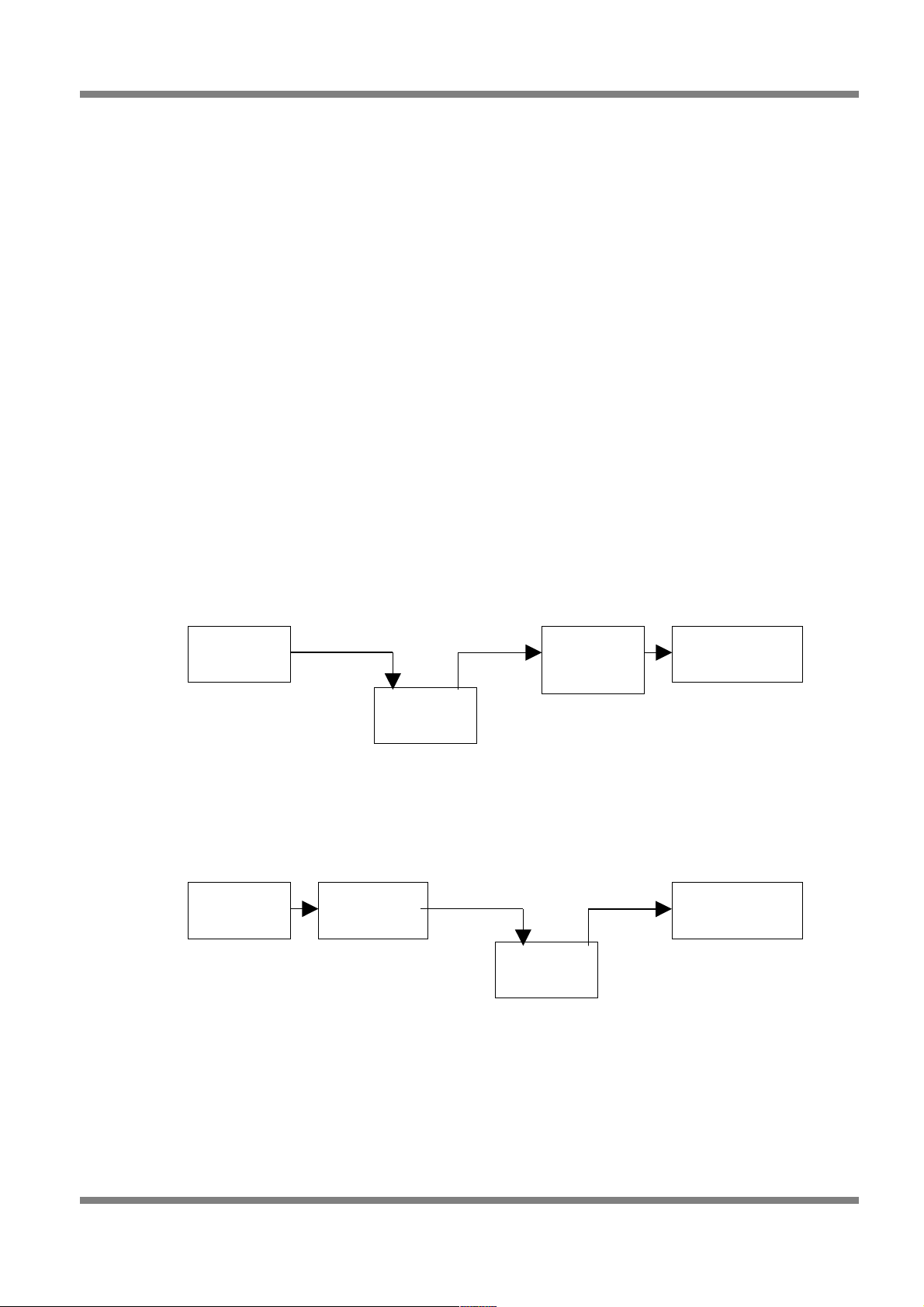
Haltech E11/E8 Instruction Manual
Edit panel contains the parameters required to be setup for each output function. Included in every set of
parameters is the ability to invert the output of the signal. Inverting the output signal does not allow the
output to drive a +12V signal, the output from the driver will still be a ground output when switched on –
inverting the output swaps the “off” and “on” signals – so what would be “on” in normal mode is “off” in
inverted mode.
Discrete Output Types
These output types are on/off style outputs. These types are available on all channels, each output is
capable of driving a maximum of 800mA, if more output current is required to drive the device connected
to that output a relay is required.
Air-Conditioning Control
The air conditioning control can perform two tasks.
Air conditioning control can be used to assist in turning off the air con compressor when under high loads.
This allows more power to be used to drive the wheels.
The air con control output can also be used to trigger increased idle speed to accommodate the extra load
from the air-con compressor.
The air-conditioning control requires input from either the air conditioning switch, or from the output of the
thermostat that drives the air conditioner compressor clutch.
If this output is used for task 1 only, then it is possible to intercept the output from the switch and connect
the output of the ECU to the air-con switch wire.
Figure 47 - AC Control Wiring Without Idle-up
If the idle control needs to be altered when the air-con compressor clutch is engaged, then the ECU must
be connected between the air-con thermostat output and the compressor clutch to ensure that the output
of the ECU has a direct relationship with the compressor clutch.
Figure 48 - AC Control Wiring With Idle-up
The A/C output control is disabled when engine speed is below the cranking RPM. This is to reduce the
load when cranking and to help prevent stalling if engine RPM falls too low.
• TPS Threshold - AC output is disabled when TPS is above this value. This removes the air
conditioning compressor load from the engine under high driver demand.
Copyright © Haltech 2008
Page: 53
Aux OutAux In
Air Con
Switch
ECU
Aux In
Air Con
Switch
Air Con
Thermostat
ECU
Air Con
Thermost
Aux Out
Compressor
Clutch
Compressor
Clutch
Page 54

Haltech E11/E8 Instruction Manual
• RPM Threshold - A/C output is disabled when the engine speed exceeds this RPM. This is to
prevent over revving the air con compressor on some high performance engines.
• Time Interval (s) - In order to prevent the A/C compressor from making rapid transitions with rapid
changes in throttle, the minimum time interval between on and off transitions can be specified
here.
See the Digital Inputs section for information on how to setup the input required for Air Conditioning
control to function.
Alternator Control (Mazda)
Some Mazda alternators require a PWM actuated signal to maintain a steady output voltage. This feature
allows the ECU to control the PWM output to achieve the desired alternator output voltage
Actual alternator control values from a NB Mazda Miata MX5:
Figure 49
• Frequency – The frequency required to control the given alternator.
• Start Duty Cycle – This duty cycle will be run when the engine is cranking, this is also the duty
cycle that the controller starts the control process at.
• Gain – Controls the sensitivity of the control system, the larger the gain the larger the change in
duty when there is an error between the actual battery voltage and the desired battery voltage.
• Target Voltage – Sets the target output voltage of the system.
• Min Duty – The minimum duty cycle the control system will output.
• Max Duty - The minimum duty cycle the control system will output.
Aux Fuel Pump
Running two fuels pumps continuously, or a single very large flow-rate pump means excessive noise and
heating of the fuel. A street vehicle with very high potential output will not need a large fuel supply at all
times. The second pump would only be activated when load demands require that the extra flow be
available.
Page: 54
Copyright © Haltech 2008
Note: The extra fuel pump cannot be driven directly by the ECU. The ECU can
be made to drive a relay to power the pump.
Page 55

Haltech E11/E8 Instruction Manual
The extra pump must be connected in parallel with the primary fuel pump. The Figure below suggests a
possible layout. The check valve is necessary to prevent fuel from being forced in the wrong direction.
Connect the power to the pump via a relay as shown. Either the positive or negative side may be switched
through the relay.
Figure 50
There are two parameters that define when the Auxiliary Pump will be switched on:
• Load Threshold - The load at which the pump will switch on.
• RPM Threshold - The RPM at which the pump will switch on.
• Time - The minimum time between successive on or off transitions.
Figure 51
BAC Idle Control - BAC idle control uses a valve to allow air to bypass the throttle plate to control idle
speed. The motor used is a solenoid style motor that moves according to the current flowing through the
BAC motor. This is similar to a voice coil in an audio speaker. BAC valve idle control is used to hold
steady the RPM when off the throttle. This method of controlling RPM at idle is done by looking at the
difference between the target idle RPM and the current RPM and adjusting the BAC valve’s output duty
cycle until the difference is zero.
See tuning section for setting up and tuning the BAC valve idle control.
BAC Hi - BAC high is a form of BAC idle control that is used for 3-wire BAC valves with two coils. These
valves are sprung so that when no coils are energised, the BAC valve sits at 50% open. Two PWM signals
are used to move the coils. One signal moves the valve from 0% to 50% open, while the other signal
moves the valve from 50% to 100% open. The BAC Hi output moves the valve from 50% to 100%. When
the target position for the valve is between 50% and 100%, this output will provide a signal from 0% to
100% duty. All idle control tuning and setup is done with the BAC Hi output. Refer to tuning section below
for details on how to tune your idle control.
Copyright © Haltech 2008
Page: 55
Page 56

Haltech E11/E8 Instruction Manual
BAC Low - The BAC low output is used to control the BAC valve when the target opening is 0% to 50%
open. When the valve target position is 0%, the output duty is 100%. When the target is 50% open, the
output duty is zero to allow the spring to return the valve to its default position.
BAC Inverted - For 3-wire BAC valves that do not have a spring to return the valve to the centre position,
use BAC and BAC Inverted to control the valve. Connect the BAC output to the coil that pulls the BAC
valve open. Connect the BAC Inverted output to the coil that pulls the BAC valve closed. The BAC
Inverted signal is a complementary signal to the BAC signal. If the BAC output is set to 70% duty, then the
BAC Inverted signal is set to 30% duty. All idle control tuning and setup is done with the BAC output.
Refer to tuning section for details on how to tune your idle control.
Battery Light
This feature allows a warning light to be connected to alarm the vehicle operator that the vehicle battery
voltage is below a certain voltage. The prescribed warning voltage level can be set in the edit menu of the
battery light setup.
Boost Control Closed Loop
Closed loop boost control allows the user to set a predefined boost level in the “closed loop boost control”
map. The ECU will then adjust the control duty cycle of the boost control solenoid to adjust the actual
boost level until the actual boost level equals the desired boost level.
Figure 52
Refer to section tuning for details on how to setup and tune closed loop boost control.
Page: 56
Copyright © Haltech 2008
Page 57

Haltech E11/E8 Instruction Manual
Boost Control Open Loop
Open loop boost control allows the user to set a predefined duty cycle for the boost control solenoid to run
at, this duty cycle is set in the “wastegate control map”. The ECU will run the boost control solenoid at the
desired duty cycle regardless of the actual boost the engine is creating.
Figure 53
Refer to tuning section for details on how to setup and tune open loop boost control.
Dual Intake Valve Control
Some late model engines possess two tuned intake manifolds seperated by a set of butterly valves. One
intake tract remains shut at lower rpm where there is less airflow, then opens as airflow demands
increase. This provides a broader torque curve. The DIV function controls the solenoid that operates this
valve.
• On RPM - The RPM above which the solenoid is energised.
• Off RPM - The RPM below which the solenoid is not energised.
The Toyota TVIS system requires the solenoid to be energised at low RPM to close the secondary intakes
and de-energised to open the secondary intakes. To achieve this logic, select the output to be inverted
within the output options window.
Figure 54
ECU Diagnostics Light
This feature allows a warning light to be illuminated when certain sensor conditions are met. This output is
useful for determining if a sensor has failed or been disconnected, it is also useful for setting a warning
light if engine temperature goes above safe levels. To access the diagnostics limits for each sensor go to
the setup menu -> sensor setup -> sensor diagnostics.
Engine Control Relay
This feature allows the 12-volt supply to the engine to be disconnected when the ECU is not powered up.
There are no parameters for this feature. The engine control relay should be wired as shown in the figure
below. The ECU is not capable of supplying power to the relay or the components it drives but can sink
the current required to energise the primary winding of the relay (ie the ECU is only capable of switching
Copyright © Haltech 2008
Page: 57
Page 58

Haltech E11/E8 Instruction Manual
the relay on not powering the engine or its components).
Figure 55 - Engine Control Relay Wiring
Extra Injector
Select extra injector output for additional staged injection. You can select as many extra injectors as the
number of free timed channels allows. The additional injector will pulse at the same time as injector 1. The
injection mode is defined by the staged injection setup found in the fuel setup page. See section fuel
setup page.
Generic Switching Outputs
The generic switch outputs can be used to drive a relay, device or warning light for any application based
on a generic ECU input. All generic switch outputs are simply on/off switches with the exception of the
generic load PWM map, this output is a fully mappable 32x32 load RPM map.
The generic switch options are as follows:
Generic Air Temperature Switch – Allows the output to be switched on and off again at the users
desired air temperatures as measured by the air temperature sensor.
Figure 56 - Genericl Air Temp Switch
Generic Coolant Temperature Switch - Allows the output to be switched on and off again at the users
desired coolant temperatures as measured by the coolant temperature sensor.
Page: 58
Copyright © Haltech 2008
12V 12V 12V
To Engine
OR
ECU Output
ECU Output To Engine
Page 59

Haltech E11/E8 Instruction Manual
Figure 57 - Generic Coolant Temp Switch
Generic Engine Time Switch – Allows the output to be switched on after a prescribed period of time after
the engine has started.
Figure 58 - Generic Engine Time Switch
Generic Load Switch – Allows the output to be switched on and off again at prescribed engine load, as
measured by the engines load sensor (MAP sensor or TPS).
Figure 59 - Generic Load Switch
Generic Load PWM Map – Allows various duty cycles to be output based on the engine load and RPM,
this map is a full 32x32 load cell map and can be found in the “maps” menu. The frequency set in the
PWM output is the frequency at which the solenoid is to be pulsed at, typically between 30 – 300 hz
depending on application.
Copyright © Haltech 2008
Page: 59
Page 60

Haltech E11/E8 Instruction Manual
Figure 60 - Generic Load PWM Map Output
Generic Road Speed Switch - The output to be switched on once the programmed road speed has been
reached and remain on until the vehicle drops below the programmed road speed.
Figure 61 - Generic Road Speed Switch
Generic RPM Switch – Output is switched only once the programmed engine RPM is reached and
remains on until the engine RPM drops below the programmed engine RPM..
Figure 62 - Generic RPM Switch
Generic TPS Switch - Output is switched on after the programmed throttle position has been reached
and remains on until the throttle position returns to a value below the programmed value.
Figure 63 - Generic TPS Switch
Page: 60
Copyright © Haltech 2008
Page 61

Haltech E11/E8 Instruction Manual
Ignition Bypass
Bypass signal compatible with some General Motors ignition systems. This function allows the ignition
system to provide the spark at 10° BTDC at cranking speeds (below 500rpm). This aids starting, once the
engine is running the bypass signal allows the ECU to have full timing control. This feature is only used on
bypass line equipt GM ignition systems.
Intercooler Fan
To assist in the operation of the intercooler, a fan can be setup to blow cool air through the intercooler.
The intake air temperature activates this fan.
Figure 0-64 - Intercooler Fan Switch
• Turn On Temp - The intercooler fan operates when air temperature exceeds this temperature.
• Turn Off Temp -The intercooler fan stops when air temperature falls below this temperature.
Intercooler Spray
To assist in the operation of the intercooler, a water spray can be setup to spray water onto the
intercooler. The intake air temperature activates this spray.
• Turn On Temp - The intercooler spray operates when air temperature exceeds this temperature.
• Turn Off Temp - The intercooler spray stops when air temperature falls below this temperature.
Intercooler spray advanced
The advanced intercooler spray requires the “intercooler spray input” to be setup and enabled. All of the
conditions in the intercooler spray advanced page must be met for the output to switch on. This output is
often used to control a CO2 intercooler cooling kit or even a methanol injection system.
Figure 65 - Advanced Intercooler Spray Output
Copyright © Haltech 2008
Page: 61
Page 62

Haltech E11/E8 Instruction Manual
Intercooler spray armed
When the “Intercooler Spray Input” is set to a “momentary switch” this output alerts the user to what state
the input button is in (this feature is commonly used when connected to the factory mitsibishi evo 9 dash).
Nitrous Activation Signal
This function controls the operation of a NOS system. It does not control the delivery of the Nitrous Oxide,
but simply turns the system on or off in certain conditions, a relay is required to trigger the NOS solenoids
the ECU output is used to trigger the relay only. The NOS system must control the delivery of the nitrous
oxide and must also provide extra fuel delivery. A switch connected to the Auxiliary Input enables the
function. Once enabled, if the conditions stated below are met, the NOS system will be activated. The
Auxiliary Input Function in the Identification must be set to NOS Switch for the function to operate
correctly.
Figure 66 - Nitrous Control Output
There are eight adjustable parameters in the nitrous activation setup:
• Max Load - If the load exceeds this value, the NOS system will be turned off. This is used for turbo
engines where the NOS system is used to help boost the turbo. Once on boost, the NOS can be
turned off. Normally aspirated engines, on the other hand, can use NOS at full load, in this case
the max load value should be set to 150kpa (ie the nitrous is always enabled). The max load value
is an absolute pressure value in kpa.
• Max RPM - If RPM exceeds this value the NOS output will be switched off.
• Min RPM - If the RPM is below this value the NOS system will not be activated.
• Min Throttle - The NOS system will be turned on above this value.
• Min Coolant Temp - The NOS system will not be activated unless the engine coolant temperature
is above this value.
• Min Time – Engine running time after which NOS can be activated.
• Ign. Retard - Amount of ignition retard when NOS is active.
• % Fuel Enrich - The percentage of fuel enrichment when NOS is activated. This is only a minor
Page: 62
Copyright © Haltech 2008
Page 63

Haltech E11/E8 Instruction Manual
correction to the mixtures in case there is a minor lean out. You must supply sufficient fuel for the
NOS system by other means also to ensure that you have sufficient fuel.
Shift Light
Shift lights can be setup for any RPM from 0 – 16000RPM. You can setup more than one shift light on
separate outputs.
Figure 67 - Shift Light Output
On RPM - Output turns on when this RPM is exceeded
Off RPM- Output turns off when engine speed falls below this value
Staging Signal
This function uses an output to indicate when the engine is in the staging section of map, i.e.. When the
load has increased beyond the Staging Load Bar in the Fuel Setup page. There are no parameters to
setup for this output. This output will not activate if staged fuel is not enabled.
Stall Saver
A solenoid air valve in the manifold may be used to allow extra air into the engine during cranking or
extremely low rpm. This can aid in starting the engine, or in preventing it from stalling if engine revs drop
too low. If the solenoid air valve is too large, the engine may stall because of its opening. The valve should
be of appropriate size to increase the idle speed by several hundred rpm. Wire the solenoid through the
output connector. There is only one parameter to be set with this function.
• On RPM - This is the rpm below which the valve will be opened. The default setting for this
parameter is 500rpm.
Tacho Output
The tacho output can be used to drive electronically controlled tachometers. The duty cycle of the
waveform is fixed with a varying frequency that changes according to the RPM.
Copyright © Haltech 2008
Page: 63
Note: The staging signal does not pulse with the other injectors. It switches on and
stays activated while the load is above the staging point. The pulsed outputs can be
configured using the Extra Injector output type.
Page 64

Haltech E11/E8 Instruction Manual
Figure 68 - Tacho output
• Tacho Duty - Duty cycle used to drive the tachometer.
• Tacho Pulses Per Rev - The number of pulses per engine revolution that the tachometer expects.
On a 4-stroke piston engine, this is typically the number of cylinders divided by two.
PWM output #1 is suggested to be used as the tacho output as PWM 1 is the only output that has a
programmable signal pullup required for some factory tachometers. The PWM 1 “pullup” controls the
voltage level of the ouput signal, ie enabling the 12v pullup outputs a 0-12V square wave, the 8V pullup
outputs a 0-8V square wave etc.
Figure 69 - PWM Output 1 Pullup Options
Test
The test output is used to fault find wiring to test if an output is properly connected. The test output allows
the user to control the output in real time from the front end at the touch of a keystroke.
Thermo Fan
The thermo fan output function is used to run thermal cooling fans that circulate air through your radiator
when coolant temperatures exceed the programmed value. You can setup more than one thermofan on
separate outputs.
After selecting the Thermofan option, the temperatures must be programmed to select when the fan turns
on and off. When wiring up a thermofan please use a relay to switch the fan power as the ECU itself if not
capable of running the fan. The ECU output is only rated to switch a relay on and not the high current
required by the fan itself.
Page: 64
Copyright © Haltech 2008
Page 65

Haltech E11/E8 Instruction Manual
Figure 70 - Thermofan Output
• Coolant Temp High - Thermo fan turns on at this temperature
• Coolant Temp Low - Thermo fan turns off at this temperature. Must be set lower than the Coolant
Temp High parameter.
• Auto Activate with A/C – When an input is correctly configured as A/C Request the thermofan
can also be automatically be activated and deactivaed when the Air Conditioning is switched on
and off.
Thermofan (duty)
The thermo fan (duty) output function is used on certain thermal cooling fans that have intelligent control
logic built into their control relays. Thermofans such these will vary their fan speed based on engine
temperature, generally as the engine temperature increases so does the fan speed. This type of thermo
fan control is often controlled by intelligent relay circuitry. The control output from the ECU varies output
duty cycle with temperature, this in turn varies the speed of the fan. This form of fan control is found in
some late model vehicles including some Mitsibishi Lancer EVOs.
Figure 71 - Thermofan (duty) Output
Torque Converter Lockup Control (TCC)
This function controls the clutch lockup solenoid on automatic transmissions that support this feature.
Locking the torque converter reduces the amount of energy lost through the transmission, providing better
fuel economy.
The solenoid activates whenever the road speed is greater than a programmed value for a given throttle
position. With the default settings, the solenoid will only activate if the engine temperature is higher than
46°C (118°F), and will be disengaged if the throttle position exceeds 70% or road speed falls below
64kph. The TCC function also provides for a 4th gear/transmission over-temperature switch input. This
signal indicates that the transmission is hot, and engaged in top gear. When this is the case, the lockup
solenoid is activated regardless of road speed whenever the throttle is more than 4% opened.
Copyright © Haltech 2008
Page: 65
Page 66

Haltech E11/E8 Instruction Manual
To use the TCC function, you must have the following:
A square wave signal road speed indicator whose frequency is proportional to road speed. (This may
require a reluctor adaptor for signal conditioning.)
Access to the wiring of the torque converter lockup solenoid and 4th gear/over-temp switch
Wire the TCC solenoid to the appropriate output line on the output connector, and, if it is available, the 4th
gear/over-temp signal to the appropriately configured Input. The 4th gear/over-temp signal must be a pullto-ground style signal.
To determine vehicle speed, a square wave signal must be applied to the road speed input connector.
This connector possesses ground and 12 volt signals for powering a Hall effect or optical sensor. A
magnetic or reluctor type signal is incompatible, and you will need to convert the output from this style of
pickup to a square wave.
Once the wiring is complete, run the ECU software in ONLINE mode and Options->Output Options page.
The parameter Road Speed Value must be set with the number of pulses expected per kilometre. If you
are unsure of the exact value for this parameter, enter an approximate number and check against the
vehicle's speedometer. Adjust the Road Speed Value until the road speed displayed on the Engine Data
Page and the actual vehicle speed agree.
Figure 72 - Torque Converter Control Output
• Road Speed - The TCC output activates when the road speed exceeds this value.
• TPS - The TCC output activates when the TPS is less than this value.
• Coolant Temp - The TCC output activates when the coolant temperature exceeds this value.
When all the above conditions are met, the TCC output activates and locks the torque converter. It is
advisable to never engage the lockup below 60 kph (40 mph).
Turbo Timer
The turbo timer is used to help cool the turbo bearing by running the engine at idle for a short period after
driving. If the engine is switch back to the ignition position whilst the car is running off the turbo timer, then
all the timers get reset.
Care should be taken to make sure the relays are wired correctly, and that an over-ride switch has been
fitted to allow the engine to be switched off manually while the turbo timer is active. See the figure below
for the correct way to wire this output. The ECU detects if the ignition switch has been turned off via the
Auxiliary Input. Therefore, the Auxiliary Input Function must be selected as Turbo Timer Input in the Digital
Inputs page.
Page: 66
Copyright © Haltech 2008
Page 67

Haltech E11/E8 Instruction Manual
Figure 73 - Turbo Timer Output Wiring
Figure 74 - Turbo Timer Output Setup Parameters
• Air Temp - The turbo timer keeps the engine on while the air temperature is above this
temperature.
• Coolant Temp - The turbo timer keeps the engine on while the coolant temperature is above this
temperature.
• Max Time - The turbo timer will turn the engine off when this time is exceeded after the ignition is
turned off.
• Rev Limit - The engine speed is limited to this RPM when the turbo timer is operating with the
ignition off.
VANOS Advance and VANOS Retard
This feature allows the operation of the variable valve timing system developed by BMW called VANOS.
This feature acts to control two solenoids on the camshaft, one solenoid advances the camshaft, the other
retards the camshaft timing. For control of the VANOS system two PWM outputs and two digital timed
inputs must be used for each camshaft controlled. One PWM will control the advance solenoid, the other
PWM will control the retard solenoid, one digital timed input will read the fixed 8 pulse signal (VANOS Ref
signal) on the camshaft, the other digital timed input will read the variable (moving) 8 pulse signal (VANOS
Inlet Cam signal) on the camshaft.
• VCT Frequency - The frequency that the VANOS solenoid should operate at, typically xxx hertz.
Copyright © Haltech 2008
Page: 67
Page 68

Haltech E11/E8 Instruction Manual
• Propional Co-eff - The speed at which the control system updates, typically between 10 – 50
depending on how quickly the system needs to react.
• Minimum Coolant Temp - The temperature at which the VANOS system will begin its operation,
below this temperature the camshafts will remain in the fully retarded position.
• Deadband - The degree of accuracy required, a deadband of 3 and the system would control the
camshaft position within 3 degrees of the target position. A deadband of 1 and the system would
control the camshaft to within 1 degree of the target position. A value too high leads to poor
accuracy, too low and the system may oscillate trying to achieve too stringent a result.
Refer to tuning guide section for details on how to tune variable cam timing.
VCT Control Output
This feature allows the operation of the variable valve timing associated with some modern engines. This
feature is designed to controlling continuously variable valve timing. There are multiple control outputs
available as each camshaft to be controlled requires its own VCT control output wire.
For each VCT control output a VCT control input is required (setup in timed input functions), this input
comes from the camshaft position sensor on the camshaft that is being controlled (most commonly the
intake camshaft is variable and the exhaust cam remains static), in which case the exhaust cam sensor
would be used as the ECUs “home” signal and the intake cam sensor is setup as the VCT control input.
Figure 75 - Variable Cam Timing Control Ouput
Page: 68
Copyright © Haltech 2008
Page 69

Haltech E11/E8 Instruction Manual
When setting up Variable Cam Control for the first time default values may need to be added into the
“PID settings” These can be accessed by clicking on the “Adjust PID settings” button. Default values
should be set as follows:
Figure 76 - Variable Cam Timing Advanced PID Settings
Refer to tuning guide section for detailed instruction on how to setup and tune variable cam timing.
VTEC (Load and RPM switch)
This feature allows the operation of the variable valve timing associated with some engines. This feature
acts purely to control a switching solenoid and is not capable of controlling continuously variable valve
timing.
Figure 77 - VTEC Output
• On RPM - The VTEC output activates when the engine speed exceeds this RPM.
• On Load - The VTEC output activates when the engine load exceeds this value.
• Off RPM – The VTEC output de-activates when the engine speed exceeds this RPM
• Off Load – The VTEC output de-activates when the engine load exceeds this value.
Both Load and RPM conditions must be met before the VTEC output becomes active.
Copyright © Haltech 2008
Page: 69
Page 70

Haltech E11/E8 Instruction Manual
Water Injection Activation
To help improve the detonation resistance of an engine, water injection is sometimes used. The water
helps to cool the intake charge and increase the resistance to detonation when it forms a vapour in the
combustion chamber. The water injection is activated by the following parameters.
Figure 78 - Water Injection Control Output
• Load - The water injection enables when the load rises above this value.
• RPM - The water injection enables when the engine speed rises above this RPM.
• Air Temp - The water injection enables when the air temperature rises above this temperature.
The water injection output activates when all the above parameter conditions are met.
Page: 70
Copyright © Haltech 2008
Page 71

Haltech E11/E8 Instruction Manual
Analogue Input Options
• Fuel Trim - With the optional trim module attached to an analogue input, the injection times can be
adjusted with the trim module. Typically the trim module is used when firing up engines for the first
time to make quick adjustments to fuel. The trim can be setup for Coarse (±50%), Medium (±25%)
and Fine (±12.5%) adjustment. Trims can also be dash mounted for changes to mixtures on the fly
whilst driving if desired.
• Ignition Trim - With the optional trim module attached to an analogue input, the ignition advance
can be adjusted with the trim module. Typically, ignition timing is only altered when tuning to allow
for rapid changes to ignition advance. The trim can be setup for Coarse (±12.5°), Medium (±10°)
and Fine (±5°).
• Turbo Wastegate Trim - With the optional trim module attached to an analogue input, the
wastegate duty cycle can be adjusted with the trim module. With the trim set to minimum, the boost
level is restored to standard with the boost solenoid de-activated. As the trim is increased to
maximum, the programmed boost from the maps is used to control boost.
• External Baro – Allows an external barometric pressure sensor (most commonly this is a 1 bar
MAP sensor) to be added to the ECU, this is rarely used as the ECU has a barometric pressure
sensor built in also.
• Wideband O2 Input - With the 5V output from a wide band A/F meter attached to this input, the A/
F ratios can be viewed and data logged against the other engine parameters to aid in tuning and
verification of the maps.
• Manual Idle - With the optional trim module attached to this analogue input, the idle control output
can be controlled by this trim. With the trim set to minimum, the stepper motor will position itself
according to the position described by Min Stepper Open Position in the idle control panel. The
maximum position will be the minimum position plus the Stepper Motor Range.
• Rotary Oil Metering Feedback - This output is used exclusively for rotary engines that have an
oil-metering pump for lubrication of the rotor. The oil-metering pump has a position sensor that is
connected to this analogue input for feedback on its position. The Feedback Min must be set with
the minimum raw count from the analogue input when the stepper motor is in the most closed
position. The Feedback Max value must be set with the largest raw count value from the analogue
input when the stepper motor is in the most open position.
• External MAP Sensor – This input enables an additional MAP sensor to be added to the system
for comparison to the MAP sensor used for measuring load. This input is most commonly used in
applications where pressure drop across a device is being datalogged. An example where this
input is used is measuring the pressure drop across an intercooler, where the MAP sensor used to
determine engine load is compared to an additional MAP sensor setup as the “external MAP
sensor” and plumbed before the intercooler. The difference between the two readings is the
pressure drop in the system. Similar methods can be used to determine throttle body efficiencies
etc.
Copyright © Haltech 2008
Page: 71
Page 72

Haltech E11/E8 Instruction Manual
• Fuel Pressure Sensor – This input enables the ECU the display and datalog fuel pressure via a
fuel pressure sensor.
• Oil Pressure Sensor – This input enables the ECU the display and datalog engine oil pressure via
an oil pressure sensor.
• Closed Loop Boost Trim - With the optional trim module attached to an analogue input, boost
levels can be trimmed down from the value set in the closed loop boost control map to a maximum
of the amount set in the closed loop boost control trim input. With the trim turned all the way
clockwise boost levels will be equal to the values found in the closed loop boost control map, with
the trim turned all the way anti-clockwise the boost is reduced by the amount set in the trim input.
• EGT Input – This input allows an Exhaust Gas Temperature input to be entered into the ECU, this
input requires the EGT thermocouple to be amplified externally (EGTs and amplifiers can be
purchased through haltech). EGT can then be used to trim fueling requirements through the fuel
correction maps.
• Air Conditioning Request - The ECU can intercept the air conditioning control to control when it
is allowed to operate and to allow for any idle up requirements when air conditioning loads the
engine. This input is connected to the switch that request air-conditioning function, or the output
from the air conditioner thermostat control box, depending on the required function. See section
for details on how to setup air conditioning control.
• Nitrous Enable - If the nitrous activation system requires an external input to arm the system, then
select this function on the digital inputs. See tuning section for details on how to setup nitrous
control.
• Auxiliary Rev Limit - To help some cars ‘launch’ from a standing start, an auxiliary rev limit can be
set via an external input. This limits the power available from the engine that helps to minimise
wheel spin. Typically, the auxiliary rev limit is set when the car is stationary and the engine is
revved up to that limit. When the clutch is released, then car is moved using only the limited engine
power until sufficient traction is gained, at which time the auxiliary rev limit is released.
• Datalog activation – To activate on board datalogging the channels need to be setup in the
datalogging setup menu and the input needs to be enabled. When the input is grounded on-board
datalogging is activated.
• Map Selection - The ECU has two sets of separate fuel and ignition maps that can be
programmed. These can be tuned differently for different fuels or different conditions. E.g. Use
fuel/ignition maps 1 for pump fuel and use fuel/ignition maps 2 for racing fuel. A switch can be
connected to this digital input to select between the fuel maps only, the ignition maps only or both.
Click on the Edit button to select which maps you wish to control with this input.
• Turbo Timer Input - When turbo timer is setup, the ECU requires an input to determine when the
ignition is turned off to start the turbo timer. See auxilary output options section on the Turbo
Timer output for more details on how to wire the turbo timer system.
• Anti-Lag Enable - When turbo anti-lag is setup to require an external input to arm the anti-lag
function, select this input function and connect your enable switch to this input. See section on
anti-lag for details on how to setup anti-lag.
Page: 72
Copyright © Haltech 2008
Page 73

Haltech E11/E8 Instruction Manual
• Transmission Overheat – Some factory vehicles are fitted with a transmission overheat switch
that alerts the user to the fact that the transmission temperature is high.
• Anti-Lag Rally Application Switch - When “antilag rally mode” is selected and the “switch” is
required this input needs to be setup. The switch is “on” when grounded. See tuning section for
more details of setting up and tuning antilag rally mode.
• Anti-Lag Launch Application Switch - When “antilag launch mode” is selected this input needs
to be setup. The switch is “on” when grounded. See tuning section for more details of setting up
and tuning antilag launch mode.
Digital Input Options
The ECU has inputs capable of accepting on/off type of input information such as from a switch. The
active state of these inputs is when the input is connected to GND. The inactive state is when the input is
not connected to GND. The input active state can be inverted by selecting an option in the ‘Edit’ dialog, so
that connecting an input to GND results in an inactive state and disconnecting the input results in an active
state.
Timed Inputs
These inputs are capable of accepting pulsed input information such as for a road speed sensor. These
inputs measure the time periods between the pulses and can process this information to provide
quantities such as Road Speed.
Input Type
Aux Input 1 Digital Only (on/off)
Pulsed Digital Input 3 Digital or Pulsed input
Pulsed Digital Input 4 Digital or Pulsed input
Pulsed Digital Input 5 Digital or Pulsed input
• Flatshift – With this input setup on a clutch activated switch the ECU will retard timing preventing
the engine from accellerating at its normal rate. This allows for the driver to remain at full throttle
without over-revving the engine. The amount if ignition retard required can be setup in the edit
menu of the aux input when enabled.
• Road Speed Input - To detect the road speed at which the vehicle is travelling, connect a square
wave pulse signal to this input that has a frequency that is proportional to speed of the vehicle. To
calibrate the road speed, click on the Edit button and set the field that specifies the number of
pulses per km.
• VCT Input – Continuous variable cam timing generally requires two camshaft inputs, one input is a
static input that does not vary with camshaft position (this input is wired to the ECU home input).
The other input measures the camshafts true position and therefore varies as the camshaft
position is changed, this signal is the VCT input and is required to be a digital 0-5V square wave
pulse signal. If the factory sensor is a reluctor style sensor (sine wave) an external reluctor adaptor
such as the haltech RA10 is required.
Copyright © Haltech 2008
Page: 73
Page 74

Haltech E11/E8 Instruction Manual
• VANOS Ref Signal - For control of BMWs VANOS system two signal inputs are required. The
VANOS ref signal reads the fixed 8 pulse signal on the camshaft.
• VANOS Inlet Cam Signal - the VANOS Inlet Cam digital timed input can be connected to read the
variable (moving) 8 pulse signal on the camshaft of a VANOS equipt engine.
• Intercooler Spray Input – When using intercooler spray advanced this input is required to be
enabled before the intercooler spray will activate.
Data Logging - See Datlogging section for Details.
Page: 74
Copyright © Haltech 2008
Page 75

Haltech E11/E8 Instruction Manual
Starting Your Engine
If your engine is a freshly built engine, make sure that you prime the engine oil system by cranking it with
no spark plugs and the injectors disconnected. Crank until the engine oil pressure turns off any warning
lights and oil pressure gauges (if fitted) read sufficient oil pressure.
Disable Injectors - To avoid accumulating unburnt fuel in your engine, make sure you disable your
injectors before you crank the engine when setting up.
Check for RPM - With your trigger set-up correctly, cranking the engine should produce and RPM figure
in the 80 – 300 RPM range depending on your engine. Make sure that the RPM reading is stable while
cranking. If the RPM signal shows “0” or the signal is erratic check the wiring for the trigger is correct.
Calibrating Ignition Timing - Now is the time to triple-check your ignition settings in the software. If the
settings are correct, turn off power to your ignition system and connect your ignition system to the ECU. It
is a good idea to check your ignition coil temperatures periodically on a newly wired system. If you find
that a coil is getting hot, then turn off the ignition power immediately and double check your wiring and
ignition settings.
Setup the ignition lock timing to a value that corresponds to an easy to read timing mark on your crank
pulley. Select a value that will allow you to easily start the engine too. Typically, engines will be clearly
marked at 10 degrees BTDC, which will also allow for easy starting.
Your injectors should still be disabled at this point.
Crank your engine while someone is watching the timing with a timing light. Check for consistent ignition
pulses while watching at what engine position the spark occurs. Adjust the Trigger Angle and/or Tooth
Offset to adjust the timing to correspond to the Lock Timing value that you have set. Typically you should
select a tooth offset that gives you a trigger angle between 50-100 degrees.
Once this is set, your ECU is now calibrated for ignition timing. Using the timing light, attach to each spark
lead and check that every spark plug is firing a spark.
Enabling Injectors - With the ignition system now calibrated and firing, enable the fuel injectors. If you
have purchased the optional trim module, now is a good time to setup the trim module to allow you to trim
±50% fuel (See section for instructions on how to setup Trim Modules). With fuel enabled, crank your
engine and adjust fuel until the engine starts. Adjust your fuel trim and fuel maps at the idle range and
load until the engine idles smoothly. Typical engine idle RPM will be 1000 RPM at about –60 to –80 kPa of
vacuum. Check that your ignition timing is still accurate and firing at the angle that is set in the Lock
Timing parameter. For more detailed information on setting the base timing see Setup Guide section
'Setting the Base Timing'.
You are now ready to tune your engine. Proceed to the Tuning Guide.
If your engine fails to start, go to Appendix C for the faultfinding guide.
Copyright © Haltech 2008
Page: 75
Page 76

Haltech E11/E8 Instruction Manual
Tuning Guide
Introduction
Before you begin this section of the manual, make sure that you are able to start your engine and achieve
a steady idle. This section of the manual will guide you through the tuning of your fuel, ignition and
correction maps for your vehicle. The Halwin software controls for tuning maps will be covered in this
section in detail.
This Tuning Guide assumes basic knowledge of automotive fuel, ignition and triggering systems. If you
find settings or concepts that are confusing or difficult to understand, please refer to the appendices of this
manual for more background information on these topics.
What are maps?
The injection times needed by the engine at different conditions are stored by the ECU in a table of
numbers called a look-up table. The ECU determines the engine's load and speed, and uses these two
parameters as an index to the table. This table is called the Fuel Map. For instance, at an engine speed of
4000 rpm and at –20kPa, the relevant number in the table may be 4.35. If the engine approximates
-20kPa at 4000 rpm, then the computer will extract the value of 4.35ms from the table as the base
injection time. This value is then adjusted to compensate for numerous conditions, such as temperature.
The ECU then holds the injectors open for that time on the next injection.
The Ignition Maps work in a similar way, except that it is the ignition advance that is stored in the look-up
table instead of the injection time.
Mapping an Engine
Mapping the engine involves filling the look-up tables with the correct values for your engine. Adjusting the
heights of the bars within the maps does this. Bars may be adjusted one at a time, or in groups. The
Haltech programming software has been designed to make engine mapping as simple and intuitive as
possible
Using Halwin for Tuning
When referring to mappable points along the load axis, the convention is to refer to them as load ‘Bars’.
The convention for referring to mappable points along the RPM axis is to use the term RPM ‘Ranges’.
Halwin 3D Maps
The 3D maps form the basis of the engine tuning process. From the basic 3D Fuel and Ignition maps, the
ECU accesses the base fuel and ignition timing requirements for the engine for a give load and RPM. The
E11 ECU allows for two base fuel maps, and two base ignition maps.
Figure 79
3D Graphic Mode
To access the 3D maps, select Maps from the menu bar until the menu opens and drops down another
selection of options. From these options, select one of the Fuel Delivery or Ignition maps. Clicking on one
of these maps will reveal a second panel that will allow you to select the 3D view for the selected map.
Page: 76
Copyright © Haltech 2008
Injection
Time
(Height)
RPM
(Ranges)
Load
(Bars)
Page 77

Haltech E11/E8 Instruction Manual
Figure 80 - 3D Maps
With the 3D map opened, you should see a screen similar to the one below
Figure 81 - 3D Maps
Copyright © Haltech 2008
Page: 77
Page 78

Haltech E11/E8 Instruction Manual
The axes of the map are Load and RPM. The height of the map represents the base injection time in
milliseconds. The selected bar appears in yellow. The current engine load and RPM is indicated by the
‘Home Pointer’ arrow that hovers over the nearest corresponding bar.
2D Map Mode
Figure 82 - 2D Maps
Basic Software Keys
To modify the fuel and ignition maps the following keys will be the most commonly used commands to
change a map value. A more detailed guide can be found below in the software setup section.
Current selected bar - The yellow bar shows the bar that is currently selected. Pressing the up/down
arrow keys will raise and lower the height of this bar.
Home Pointer - The green pointer shows the bar nearest to the current engine speed and load. Hitting the
‘Home’ or 'spacebar' key will select the bar the engine is currently operating at.
Left/Right Arrows - These keys moves the bar selector so that you can work on all the bars individually.
‘n’ key - Shows the next RPM slice of the map. For example, if you are currently displaying the 2D slice
representing the 500 rpm range, then pressing ‘n’ will move the display to show the next increment which
will typically be the 1000 rpm range.
‘p’ key - Shows the previous slice of the 3D map.
Up/Down Arrow - Increase or decrease the height of the bar. Pressing Ctrl-Up/Ctrl-Dn will reduce the size
of the increment to the finest resolution. Pressing Shift-Up/Shift-Dn will increase the size of the increment.
PgUp/PgDn - This increases or decreases the height of the bar in larger increments than the arrow keys.
CTRL Arrow – selects multiple load bars in the map.
ALT Arrow – deselects load bars that have been selected.
Page: 78
Copyright © Haltech 2008
Page 79

Haltech E11/E8 Instruction Manual
Numeric Mode
To view the map data in its most basic form, the numeric values can be displayed and edited in table form.
The highlighted green pointers to the right of the 2D map are the “Home” markers that indicates the value
closest to the current engine operating parameters.
Figure 83 - Text View Maps
The values from this table can be copied and pasted into Microsoft Excel if required.
Variable Load and RPM Points
To modify the variable load and RPM values for the given bar or range, select your map and display in
Numeric Mode as described above. Edit from the menu bar and un-check the option Lock Variable Points.
This will unlock the first row and column to allow you to change the load and RPM at which the given bar
or range represents.By default the spacing for load values is evenly spaced load over 32 bars, for the
given 1 Bar, 2 Bar or 3 Bar sensor. The default spacing for RPM ranges is 500rpm over the 32 bars to
give ranges from 0 RPM to 15500 RPM. When modifying the variable load and range values, make sure
that all values are always ascending as you move across the bars, or down the ranges.
Figure 84 - Unlocking the load points
Copyright © Haltech 2008
Page: 79
Page 80

Haltech E11/E8 Instruction Manual
Halwin 2D Maps
There are other tables in the ECU, such as those used for temperature corrections. They are indexed by
only one parameter, and so are not divided into ranges. These tables are also called maps. An example of
this is the 3D coolant temperature map as shown below.
Figure 85 - 2D Temperature Correction Map
Fuel Maps
The E11 ECU has two base fuel maps from which the injection is calculated (fuel map 1 and fuel map 2).
These maps contain the base injection time for the given load and RPM at which the engine is operating.
The base fuel map has the greatest influence on the air/fuel (A/F) mixtures. The base map that is used
can be selected from the Main Setup page. The selection can also be made from an auxiliary input. See
auxilary inputs section for details on setting up dual mapping using an auxiliary input.
Tuning Your Base Maps
To tune your base fuel map:
Setup your A/F ratio measuring equipment to measure the A/F for the engine that is to be tuned.
Check which base fuel map is used and select the appropriate map in the front-end software to tune.
Ensure that all correction maps such as coolant temp and air temp corrections are turned off or set to zero
correction at this stage.
Confirm base timing is correct with timing light (for more information see setup guide section of manual).
Ensure that the ignition timing is set conservatively to ensure that it does not ping if a momentary lean
condition is experienced.
Page: 80
Copyright © Haltech 2008
WARNING
Driving a vehicle over time, on poorly tuned maps can lead to engine damage
over that period. In order to ensure that your fuel maps are correct, a wide-band
Air/Fuel ratio meter must be used at some stage to measure the Air/Fuel ratio
over all engine loads and speeds at which you intend to operate the vehicle.
Page 81

Haltech E11/E8 Instruction Manual
Warm the engine up to operating temperature.
Adjust the idle control or throttle stops to enable the engine to idle at the desired engine speed.
While watching the A/F meter, adjust your idle mixtures as lean as possible whilst ensuring that you can
maintain a steady idle without any misfiring.
While leaving the engine un-loaded, rev the engine in neutral through the rev range over which the engine
will be operated. Set all the mixtures close to 14.7:1 in the non-loaded part of the load range.
With the aid of a dynamometer or an alternative method of applying load, step through the load range for
each given RPM range and adjust your A/F ratio to suit. See the following sections for more details on
tuning the various ranges of the base maps.
Tuning for Idle
The idle mixture is very sensitive to correct bar height. Idle injection times are usually around 1.5 to 2.5
ms. If the injection time at idle is much lower than this, it may become difficult to set accurate idle and
cruise air/fuel ratios.
If the engine is hunting at idle, then the map is probably too lean, particularly at the 500 rpm point. Watch
the movement of the map arrow carefully. The map arrow should remain stable while the engine is idling.
If the arrow is moving excessively in a MAP based system, then it may be necessary to use the Zero
Throttle Map.
Remember that the ECU interpolates against both rpm and load. If the engine is idling at 800 rpm, then
the injection time is computed as 60% of the value from the 1000 rpm range, and 40% of the value from
the 500 rpm range, so both ranges would have to be adjusted to get the correct mixture. Similarly, if the
idle mixture is reacting poorly to changes of the bar indicated by the map pointer, then try adjusting the
adjacent bars. Wait for the engine to heat to operating temperature before performing further changes to
maps.
Tuning With No Load
Using the throttle only, increase the engine speed to 1000 rpm. If the engine is at exactly 1000 rpm then
only that range needs to be adjusted. Adjust for the crispest engine response. Engines will usually idle
rich, then head towards stoichiometric mixture at higher speeds. Repeat for 1500, 2000, 2500, 3000 rpm
etc. The engine should now start and fast idle evenly. You should also have the engine running at
operating temperature before doing any tuning of the base maps. Go to the Engine Data Page at this point
and check all the sensor inputs are reading correctly, and that the temperatures have stabilised before
continuing.
While free revving at higher engine speeds, check the engine speed on the computer. If it becomes
erratic, or fails to follow the actual engine speed correctly, check Section 2 on setting the trigger.
Applying Load to the Engine
Once the engine has been tuned properly for no load conditions it is possible to begin loading the engine.
The best method of applying load to the engine is using a dynamometer. However, if access to a dyno is
not possible the engine can be tuned on the road.
On the Dyno
Whether the vehicle is on a chassis dyno, or the engine on an engine dyno, the principles of programming
the Haltech ECU are the same. Take the engine rpm up to 1000 and apply partial load and adjust the
1000 rpm range. Return the engine to idle and on the 1000 rpm range adjust the bars to draw a straight
line from the idle point through the part load setting tested. Continue, adding more load, up to the full load
settings. This should be a fairly good approximation to the required curve. Repeat this for the 1500 range,
2000, 2500 etc. The engine should be fairly drivable at this point.
Copyright © Haltech 2008
Page: 81
WARNING
To avoid engine damage, an engine should always be tuned rich then slowly leaned
out until the desired AFR is reached.
Page 82

Haltech E11/E8 Instruction Manual
Full load tuning should be approached with caution. An engine at full load that is too lean may begin to
detonate and cause damage to engine components. Before loading the engine, increase the heights of
the right-most bars so that they are higher than the line projected by drawing a straight line from the idle
and free-rev settings and through the part-load settings.
On the Road
Tuning on the road is similar to tuning on the dynamometer, but with hills, acceleration, gear-ratios and
brakes providing the necessary retarding force. Although it is harder to maintain constant load and speed,
it is still possible to use the same procedure used on the dyno. It will be necessary to have one person
drive while another does the tuning.
Load the engine by selecting an appropriate gear and either driving up a constant grade hill, applying the
brake or handbrake.
Fine Tuning the Engine
When fine-tuning the engine for the road, the same principles apply to all engines. Under full load at all
rpm the fuel mixture should be rich. On naturally aspirated cars, an air to fuel ratio of around 12.5:1 to
13.5:1 is usually best. On forced induction vehicles (turbo or supercharged), the air to fuel ratio may go as
rich as 10.5 but should not be leaner than approximately 12.5. Forced induction vehicles may make more
power with leaner mixtures, but the excessive combustion chamber heat may cause damage to engine
components.
When cruising (light to medium load) the mixture should be as close to stoichiometric (best mixture) as
possible and decelerating conditions may allow the engine to be run lean to save fuel. This will result in a
particular shape for the map.
Note: All maps for all engines should be smooth. A map with a "lumpy" curve is most likely wrong. If,
when you have finished tuning, the map does have lumps in it, try to make it visually smooth.
Using the Haltech Quicktune Feature
The Haltech Quicktune feature can be used only if the ECU has a calibrated wideband O2 Sensor input
setup. The calibrated wideband O2 input will be the output of an external wideband O2 sensor product
such as the Haltech wideband O2 controller, other wideband controllers that have a 0-5V calibrated output
are also acceptable (INNOVATE, FJO, AFX, M&W Ignitions, TECH-EDGE and many other Wideband O2
controllers have this capability).
Once an auxilary input has been correctly setup and calibrated with a wideband O2 sensor input (go to the
setup menu -> sensor setup -> calibrate sensors -> wideband O2 controoler, to adjust the wireband O2
sensor calibration) the target air to fuel ratio table can be setup. This map is found in the maps menu
under target AFR map:
Page: 82
Copyright © Haltech 2008
WARNING
Be very careful using the brake to load the engine. The brakes can get very hot
and suffer from brake fade (reduced braking capability) and vehicle control may
become unpredictable. All road testing should be done at low speed.
Road tuning should only be performed on a closed track or private road.
Page 83

Haltech E11/E8 Instruction Manual
Figure 86 - Target AFR Map
With a correctly configured wideband O2 sensor input and the target AFR map set to the desired air to
fuel ratio the quicktune feature is ready to be used. To use the quicktune feature open the fuel map, with
the fuel map open pressing the “Q” key on the keyboard activates quicktune and adjusts the fuel map
value for the current load point the engine is operating at. The ECU does this by comparing the actual
AFR as measured by the wideband O2 sensor to the desired AFR as set in the target AFR map, the
difference between these two values is added or subtracted from the value in the fuel map until the
desired AFR is reached.
It is important to note that when the Q button is pressed the ECU only makes an adjustment to the load
and RPM point the engine is actually operating at regardless of the number of mapping points you may
have selected. For this reason best results are achieved when the RPM and load points are in the middle
of a map cell when the Q key is pressed.
Tapping the Q button multiple times in quick succession will yield poor results as the system relies on
accurate feedback from the wideband O2 sensor.
Pressing the 'W' key copies the calculated quicktune map value into the next load bar to the right of the
adjusted load bar and the same two corresponding bars in the next RPM range.
Copyright © Haltech 2008
Page: 83
Page 84

Haltech E11/E8 Instruction Manual
Ignition Maps
The E11 ECU has two ignition maps from which the ignition advance angle is calculated. These maps
define the base ignition timing for the given load and RPM at which the engine is operating. The default
ignition map that is used can be selected from the Ignition Setup page.
Figure 87 - Ignition Setup Page
The selection can also be made from an auxiliary input. See auxiliary inputs section for details on setting
up dual mapping using an auxiliary input.
Make sure that your base fuel maps are fully tuned before attempting any mapping of ignition advance.
Incorrect fuel requirements can cause pinging or detonation that is unrelated to incorrect or too much
ignition advance.
If you have access to a dynamometer, use it to apply load to the engine and increase the advance from a
conservative value until peak torque is attained for every load and RPM point. Avoid sustaining an engine
under high load and engine speeds for any length of time.
It is good practice when tuning the high load bars to load the engine briefly before backing off and tuning
the map while off load, then re-applying the load and comparing. Avoid holding the engine on high load
whilst tuning to keep engine stress and heat to a minimum.
The process for tuning the load points and RPM ranges are very similar to tuning for fuel. Instead of
aiming for good mixtures however, you should be aiming for maximum torque for the given load and
Page: 84
Copyright © Haltech 2008
WARNING
Driving a vehicle over time, on poorly tuned maps can lead to engine damage
over that period. Before adjusting ignition, ensure that your fuel maps provide a
safe operating Air/Fuel ratio. When adjusting ignition, always ensure that the
engine does not detonate or ping over all the engine speeds and loads at which
you intend to operate the vehicle.
Page 85

Haltech E11/E8 Instruction Manual
engine speed. You will achieve maximum power by aiming for maximum torque at all engine speeds.
Tuning For Idle
Typical idle speeds usually sit between 500 RPM and 1000 RPM. In order to assist the idle control
mechanism to achieve a steady engine speed, it is advisable to ensure that the ignition advance at the idle
loads between 500 and 1000 RPM are similar if not the same. It can be helpful to actually have the
advance of the 500 RPM range to be slightly higher than the advance at 1000 RPM so that as engine
speed dips, the increase in ignition advance tries to raise the engine speed. This will help the engine to
find a stable equilibrium.
Ignition Quickmap
To save time when tuning the ignition maps the ignition quickmap feature can be used to build a base
ignition map before fine tuning on a dyno or the road. This feature can be found under the options menu.
The ignition quickmap has 6 user definable fields to be filled out that will set the basis for the base map to
be built up upon, they are as follows:
Figure 88 - Ignition Quickmap
• Ignition advance at idle – Total ignition advance at idle.
• Ignition advance at peak torque (atmo)(deg) – Total ignition advance when the engine is at peak
torque and manifold pressure is equal to atmospheric pressure (wide open throttle naturally aspirated).
• Peak torque RPM – The RPM at which peak torque occurs, this value is used to determine at which
RPM point to use the 'ignition advance at peak torque' value.
• Additional ignition advance at light load (deg) – Addition ignition advance on top of the
atmospheric (wide open throttle) advance to be added when the engine is at light load.
• Ignition retard per load point under boost (deg) – Ignition retard per load bar in the ignition map
when an engine comes into positive pressure. Take care when setting this value as it the pressure
variation in pressure between load points is dependant heavily on the MAP sensor used (ie a 2 bar
MAP sensor has a load point every 6.4kpa whereas a 3 bar MAP sensor has a load point every
9.7kpa).
• Additional advance at maximum RPM – Additional ignition advance above the peak torque advance
at the engines maximum RPM (maximum RPM is based on the value set in the rev limiter setup).
Copyright © Haltech 2008
Page: 85
Page 86

Haltech E11/E8 Instruction Manual
Fuel Correction Maps
Air Temperature Correction
This map compensates for the change in density of the intake air charge when the intake air temperature
changes. Colder air is more dense which requires more fuel to be added in order to maintain a steady
combustible mixture.
The Fuel Air Correction Map is accessed via the Fuel Maps and Set-up Menu. Across the bottom of the
map displayed is the inlet air temperature. An arrow appears showing the closest bar that the system is
using. A horizontal line splits the map displayed. Bars above this line indicate a positive correction making
the mixture richer. Bars below the line indicate a negative correction making the mixture leaner.
Figure 89 - 2D Air Temperature Compensation Map
Coolant Temperature Correction
An engine requires more fuel when it is cold than when it is hot. This is a result of low manifold and incylinder temperatures where fuel sticks to the walls and doesn't atomise properly. The Haltech system
corrects for this by using the Coolant Temp Map to define the relation between engine temperature and
extra fuel required. The ECU will automatically reduce the amount of coolant correction applied to the
engine as the throttle is opened and air speed increases. The Fuel Coolant Map should not be adjusted
until the Fuel Maps are correctly tuned at operating temperature.
Access the Fuel Coolant Map from the Maps Menu. The map defines the percentage increase in fuel at
any given engine temperature. The ECU is supplied with a default coolant map that may not need to be
modified. If the coolant map requires modification, the changes should be done ONLINE and while the
engine is warming. Start the cold engine and adjust the Fuel Coolant Map so that the engine idles evenly.
You should not touch the throttle while adjusting this map. Follow the arrow as the engine warms to
provide good running mixtures up to operating temperature, where there should be zero coolant
correction.
Page: 86
Copyright © Haltech 2008
Page 87

Haltech E11/E8 Instruction Manual
Figure 90 - Coolant Temperature Correction Map
Battery Voltage
The Haltech ECU uses intelligent fuel injection driver circuitry that compensates for changes in battery
voltage. As the battery voltage falls, the injectors will take longer to turn on and so reduce the effective
open time. To compensate, the ECU applies the Battery Voltage Map to increase the injector ‘on’ time as
the voltage drops. This map can also be considered as an injector dead time map.
Figure 91 - Battery Correction Map (Injector Dead Time)
This map should not be used to compensate for a deficient electrical charging system on a vehicle.
Copyright © Haltech 2008
Page: 87
Page 88

Haltech E11/E8 Instruction Manual
Prime
To aid in starting a cold engine, the prime map defines how much fuel to inject on the first cycle on
injections for each cylinder or rotor. The fuel injection opening times in this map are much larger than what
can be programmed in the base fuel maps. An A/F meter will not be very helpful in setting up this map
since the time that this map is used is so short. A process of trial and error is the easiest way to set this
map up. Simply increase the values in this map for the given temperature until the engine can be started
easily.
Figure 92 - Fuel Prime Map
Over priming the engine will cause it to flood and not start. To clear a flooded engine, open the throttle
fully and continuously crank the engine. Do not pump the throttle, as this will only worsen the problem.
Post Start
On some motors, in particular rotaries there may be a problem with vapour-lock (fuel which due to heating
of the fuel rail has vaporised). The additional fuel at start up allows the vapour in the fuel rail to be purged
through the injectors and also allow enough fuel to be injected into the motor to allow stable operation.
Post start can also be used to give extra enrichment when the engine is cold to assist drivability. When
used for this purpose, try to do the majority of your compensation using the coolant temp map and only
use the post start map after the coolant temp map is properly programmed.
The Post Start Map is accessed via the Maps menu. It covers a time of 128 seconds with each bar
corresponding to 4 seconds of time. The time starts after the RPM exceeds the Max Crank RPM.
In the Main Setup, a post start correction above the operating temperature, and below the operating
temperature are available. The operating temperature is also defined in the Main setup.
Seperate maps are available for both above the operating temperature and below the operating
temperature in the fuel correction maps page.
Page: 88
Copyright © Haltech 2008
Page 89

Haltech E11/E8 Instruction Manual
Figure 93 - Post Start Fuel Map
Barometric Pressure
If you are using MAP for load sensing on your engine, then it is unlikely that you will need to worry about
Barometric compensation for fluctuations in ambient barometric pressure. If you are using TPS for load
sensing, Zero Throttle maps or Full throttle maps, then read on to learn how to configure Barometric
Pressure compensation maps.
Fluctuations in barometric pressure vary the density of the intake air of the engine. At lower barometric
pressure, the air density is lower (there is less oxygen in the air), and therefore the amount of fuel
delivered to the engine must be reduced. This is necessary when a large change in altitude is expected
during a driving period (a Hill Climb event such as Pikes Peak in the USA is a good example).
The ECU has an on board Barometric Pressure sensor that is used to measure the ambient air pressure.
To compensate for the fluctuations in atmospheric conditions, the Barometric Correction map allows
correction to your injection times of up to ±50%.
Zero Throttle
One problem that often occurs with performance engines is rough idling. The manifold design, cam
characteristics, etc. can cause instability in the airflow. This makes fuel metering difficult. In particular, the
Map sensor often cannot correctly read the manifold pressure, as it is non-existent, weak, or pulsing too
much. In many cases though, once the engine has some speed, the manifold pressure signal is useable.
The best method of mapping the engine is using the manifold pressure as the load. If in this configuration
idling is causing a problem, the Zero Throttle Map should be tried. This Map maps the fuel delivery at zero
throttle below 2000 rpm. There are a few requirements that need to be met before you can use this Map.
Firstly, your throttle position sensor must be calibrated properly. Secondly, the Map relies on there being a
consistent airflow at zero throttle for a given engine speed. That means that devices such as idle speed
motors that vary the airflow at zero throttle will not allow the Zero Throttle Map to operate correctly.
Full Throttle
The manifold and throttle body design can also cause problems tuning at full throttle on normally aspirated
engines. In some cases, the manifold pressure can reach close to atmospheric pressure before full throttle
is reached. This means that bars close to the full load bar on the Fuel Maps can interfere with the full load
Copyright © Haltech 2008
Page: 89
Page 90

Haltech E11/E8 Instruction Manual
bar due to the interpolation between the two bars.
If you are experiencing difficulties maintaining air to fuel ratio at full throttle, it may be necessary to use the
Full Throttle Map to set the full throttle mixtures. The Full Throttle Map is activated above the value set in
the Full Throttle Threshold in the Fuel Set-up, and has one programmable bar every 500 rpm up to 15500
rpm.
Figure 94 - Barometric Pressure Correction Map
Throttle Pump Maps
The manifold pressure sensor used with the ECU is very fast. It can respond much faster than is required
to track any sudden changes in load on your engine. However, the manifold pressure seen at the sensor
input may not change as quickly as what is seen by the inlets to the combustion chamber, due partly to
the length of the connecting pipe. This delay can be reduced by keeping the length of vacuum hose
between the inlet manifold and the pressure sensor as short as possible. Even with very short vacuum
hose lengths there may still be a lag between a transient pressure occurring and the pressure reaching
the sensor.
Further, when the throttle is cracked open, the sudden change in pressure forces fuel out of atomisation
and onto the manifold walls, so it fails to enter the combustion chamber properly atomised, and the engine
hesitates. This can be corrected by adjustment of the Throttle Pump parameters.
To overcome any lean out during sudden throttle movement, the Haltech system uses a throttle
accelerator pump function. This function delivers extra fuel during sudden throttle movements. The
Throttle Pump is accessed from the Maps Menu.
The throttle pump values should be set up after the fuel and maps are correctly tuned for steady load
running. Attempting to smooth out engine transients before the fuel maps have been optimised for steady
state running may become confusing. The throttle pumps should be adjusted by trial and error to give
optimum throttle response in each rev range. Generally, you may not need much above 3000 rpm, but
could expect much higher values below 1500 rpm.
Note that throttle response can also be affected by poor manifold design. If you have designed your own
inlet manifold you may find that although the engine runs well at steady load it leans out if the throttle is
opened suddenly. This will occur if the fuel injectors are poorly positioned and the fuel is wetting down the
walls of the inlet manifold rather than remaining as a mist.
Page: 90
Copyright © Haltech 2008
Page 91

Haltech E11/E8 Instruction Manual
The throttle pump setup allows the tuning of:
How much enrichment is needed for a given RPM, throttle position and TPS rate of change.
The biasing of the enrichment between asynchronous* and synchronous* according to a given RPM.
The speed at which the synchronous enrichment decays.
Note the rate of change of throttle position is how far the throttle moves over a 10ms time frame. A fast
throttle movement could have a TPS rate of change of 15% this means that in a time frame of 10ms the
throttle position moved 15%. A slow throttle movement could have a TPS rate of change of 1%, which
means that in a time frame of 10ms the throttle position only moved 1%.
Figure 95 – Throttle Pump Setup Screen
• asynchronous enrichment (addition injection pulses) is where the ECU adds additional injection pulses
after the initial fuel injection event. Synchronous enrichment invloves the ECU extending the original
injection pulse – best results are achieved by using a combination of both synchronous and
asynchronous enrichment.
Throttle Pump Settings
• Max Asynchronous Pulses This is the maximum number of extra injector pulses that can happen
per injector output during an enrichment event.
Range: 0 – 10 pulses.
Default: 5.
• Throttle Deadband A rate of change of throttle position greater than this value will trigger an
enrichment event.
Copyright © Haltech 2008
Page: 91
Page 92

Haltech E11/E8 Instruction Manual
Range: 0.0 – 10.0 %.
Default: 0.5 %.
• Delay Between Enrich Events The minimum time between asynchronous enrichment
events. This is to stop excess fuelling when constantly pumping the throttle.
Range: 0.00 – 2.00 sec.
Default: 0.80 sec.
• Overall Trim The trim value scales the fuel enrichment. 0% makes no changes to the fuel
enrichment. 100% will add an extra 100% fuel to the enrichment.
Range: 0.0 – 300.0 %.
Default: 100.0 %.
Throttle Pump Maps
Enrichment Sensitivity Map
This map allows for the tuning of the amount of enrichment needed according to a given RPM and
throttle position. In general more enrichment is needed at a low throttle position because a change will
cause a larger in rush of air than at a higher throttle position. At a low RPM more enrichment is needed
because of low air speeds and the atomisation of fuel is poor. This becomes less of a problem as the
engine goes up in RPM and airflow increases. The value in this map represents the enrichment needed at
the maximum TPS rate of change. This map is the first to be tuned but also make sure that the right hand
side of the TPS Rate Of Change Sensitivity Map equates to the maximum TPS rate of change achievable
with a sensitivity value of 100%.
TPS Rate Of Change Sensitivity Map
With the Enrichment Sensitivity Map tuned for a maximum TPS rate of change slower throttle
movements can be scaled accordingly with the TPS Rate Of Change Sensitivity Map. The right hand side
of the map should contain the maximum TPS Rate of change in its axis value and 100% in its map value.
For slower throttle movements (lower TPS rate of change values) a smaller percentage value can be put
in the map.
Percentage Asynchronous Enrichment Map
This map determines what percentage of the fuel enrichment goes to the asynchronous type of
enrichment. 0% in the map means that all of the fuel enrichment will be delivered synchronously. 100% in
the maps means that all of the fuel enrichment will be delivered asynchronously. Note that if the
enrichment value exceeds 9.5ms (the maximum size of an asynchronous pulse) the rest will be delivered
synchronously. In General at a low RPM, when the injection events are further apart, the asynchronous
fuel enrichment helps deliver the extra fuel straight away. At a high RPM asynchronous enrichment is not
needed because regular injection events are more frequent.
Synchronous Enrichment Decay Map
This map determines how fast the synchronous enrichment decays back to zero. The units
entered in are milliseconds per engine cycle. E.g. a value of 0.5 will mean that the enrichment will decay
0.5ms every engine cycle. The bigger the value the faster it will decay.
Coolant Correction Map
This map applies a correction factor to the fuel enrichment based on the coolant temperature. E.g.
100% gives 100% extra fuel enrichment.
Shortcut Keys - For Mini Maps
• Page Up Increments map value.
• Page Down Decrements map value.
Page: 92
Copyright © Haltech 2008
Page 93

Haltech E11/E8 Instruction Manual
• L Used to linearise between two points.
• V Used to change the value in a cell or multiple selected cells.
Other
• Ctrl T Opens throttle pump setup page without having to open fuel setup.
Injector Phasing Map – for Sequential Fuel Injection
The timing (or phasing) of sequential or semi-sequential injections is set via the Injector Phasing Map.
If the Injection Angle field is set to ‘End of Injection’, then this map sets the End of Injection angle, in
degrees BTDC compression, against the engine speed. This allows the injection to be completed before
the inlet valve opens. The ECU then times the start of injection, based on the trigger, so that the injection
is completed by the specified engine angle. If the ECU calculates that there is insufficient time to complete
injection before the specified End of Injection time, then injection will continue past this time.
If the Injection Angle field is set to ‘Beginning of Injection’, then this map defines the angle at which the
injection will begin BTDC compression. This mode is not often used, as the varying pulse width of the
injections will not ensure that the injection pulse finishes before the valve closes. This could lead to fuel
sitting in the manifold without any airflow to keep the fuel in suspension.
Engines with conservative cam profiles will notice very little difference between the injector phase angle
settings.
For 4-stroke engines, the typical usable range for injection angle is from 180 to 540 degrees BTDC.
For rotary engines, the typical usable range for injection angle is from 90 to 270 degrees BTDC. Any
angles greater than 360 degrees will be interpreted as 360 degrees BTDC.
Figure 96 - Sequential Injection End of Injection Map
Copyright © Haltech 2008
Page: 93
Page 94

Haltech E11/E8 Instruction Manual
Staged Injection
Figure 97 - Staged Injection Setup
Staged injection operates differently depending upon if the engine type is piston or rotary. When a rotary
engine is selected and Staged injection is enabled, a second fuel channel for each rotor is automatically
configured. Staged injection is much more common on rotary engines.
When using staged injection on a piston engine, you must configure Extra Injector outputs in the Auxiliary
Outputs to designate how many secondary injectors are available and on which outputs they appear
Staged Injection Modes
Primary Hold Mode
To minimise any step effect when the staged injectors begin, a Primary Hold Mode for staged injection is
available.
In Primary Hold Mode, the primary injectors hold at the current pulse width when the staging bar is
exceeded. The secondary injectors then begin to fire. However, when secondary injectors begin injection,
they cannot begin to inject smoothly from zero injection time due to the injector dead time of the
secondary injectors. This means that when the secondary injectors start, they must start from around 1ms
of injection time to overcome the effects of the injector dead time.
The Staged Dis-enrichment field is the amount of injection time that the primary injectors are reduced
when the secondaries begin. This is to compensate for the injector dead time of the secondary injectors.
Figure 98
Common Mode
In Common Mode, the pulse width of the primary injectors increase up to the staging bar as normal. When
the staging bar is exceeded, the secondary injectors begin to operate and both the primary and secondary
injectors begin to pulse at the same pulse width.
Page: 94
Copyright © Haltech 2008
Load
Primary Injectors
Load
Secondary Injectors
Injection
Time
Injection
Time
Staging Bar
Staging Bar
Dis-Enrichment
Page 95

Haltech E11/E8 Instruction Manual
Figure 99
Staged Injection Angle Split Map
This map only applies to Staged injection for rotary engines. When piston mode is used, the auxiliary
injectors are pulsed at a fixed angle.
When staged fuel injection is enabled, the secondary injectors are often mounted further up the intake
manifold tract. In order to tune the injection timing of the secondary injectors, it is desirable to fire them
slightly ahead of the primary injectors. This map defines the timing split between the primary and
secondary injectors. That is, a split angle of zero degrees will fire the secondary injectors at the same
angle as the primary injectors. A value of 10 degrees in this map will cause the secondary injectors to fire
10 degrees after the primary injectors have fired.
Staged Injection Map
The Staged Injection Map is a 32 bar map that goes across RPM. The bars in this map are additional load
bars that are used in the interpolation on the way down from loads above the staging bar to loads below
the staging bar.
Figure 100
When setting up for staged injection, there is a discrete point at which the injection times must cross over
when the secondary set of injectors turn on. In order to maintain steady mixtures, an additional load bar
must be inserted for every RPM range, at the point where the staging injectors start. This is to allow the
linear interpolation to calculate the correct fuel requirements when crossing the staging bar from low to
high loads and when crossing from high to low loads.
Copyright © Haltech 2008
Page: 95
Injection
Time
Load
RPM
Staged Injection
Map
Staging Bar
Load
Secondary Injectors
Injection
Time
Load
Primary Injectors
Injection
Time
Staging Bar
Staging Bar
Page 96

Haltech E11/E8 Instruction Manual
Figure 101
O2 Closed Loop Tuning
Narrow Band Sensors
By fitting an oxygen sensor to the exhaust system of an engine, the ECU is able to perform corrections
based on feedback from the O2 sensor to maintain a consistent air-fuel ratio around the stoichiometric
mixture. The stoichiometric mixture is when exact amount of fuel is provided to consume all the oxygen of
the air drawn into the engine, without any unburnt fuel remaining after combustion. Using closed loop fuel
control adapts for small variations in fuel quality and day-to-day running, provides better fuel economy and
lower emissions. Closed loop control does not compensate for poor tuning however, and only allows for
small mixture changes that are already close to the correct target mixture.
Figure 102 - Narrow Band O2 Sensor Output
A Typical lambda sensor output
An oxygen sensor (or lambda sensor) is placed in the exhaust gas stream usually after the collector but
before the catalytic converter. The O2 sensor possesses an output voltage characteristic similar to that in
the diagram above. When the exhaust gas is free from oxygen (i.e.. mixture is rich), the sensor reads
around 1 volt. When there is an excess of oxygen, the sensor reads closer to 0 volts. Most oxygen
sensors' transfer curves change very suddenly around stoichiometric mixtures.
The object in closed loop control is to measure the voltage of the oxygen sensor, determine whether the
engine is running lean or rich, and compensate accordingly by adjusting the injection time. The ECU may
overcorrect slightly, and then will pull the mixture back towards the desired air-fuel ratio. This slight
oscillation either side of stoichiometric mixture aids the function of the catalytic converter.
The characteristic of most narrow band sensors only enables accurate measurement about the
stoichiometric mixture point. As a result, O2 closed loop is only useful under cruise and light load
conditions where a stoichiometric mixture is desirable. Most narrow band O2 closed loop systems actively
Page: 96
Copyright © Haltech 2008
Staging Bar
-100
-90
-80
-70
-60
-50
-40
Extra bar from
staged injection
map
-100
-90
-80
-70
-60
-50
-40
Staging Bar
With Staged Injection Map
Without Staged Injection Map
Rich spot between
–70 and –60 load
points
Page 97

Haltech E11/E8 Instruction Manual
detect only the cruise and light load conditions and only uses O2 closed loop correction under these
conditions. It is not recommended to use O2 closed loop when under high loads and engine speeds where
mixtures should be richer than stoichiometric to ensure cool operation of the engine and higher margins
against detonation.
Closed loop operation is always disabled whenever there are other corrections operating such as throttle
pump corrections, or deceleration cut enrichments. Closed loop control is also disabled until the Engine
Operating Temperature threshold is exceeded.
In addition to above criteria, O2 closed loop operation will not operate under the following conditions:
Throttle pump enrichment is active.
Engine is not above the operating temp threshold as defined in the Main Setup.
Deceleration Fuel cut is performing cut or enrichment operations.
Figure 103 - Fuel Setup Page
Settings
• Low RPM Limit - The minimum RPM at which O
2
control will happen. If this value is greater than
‘Idle RPM Below’ value then O2 control at idle will be disabled.
• High RPM Limit - The maximum RPM at which O
2
control will happen. Having O2 control off at RPM
greater than this value will help to steady mixtures at high RPM, which are more sensitive to
fluctuations.
• Max Enrich Incr % - Maximum percentage increase in fuel that is allowed by the O
2
controller. (Max
25%).
• Max Enrich Decr % - Maximum percentage decrease in fuel that is allowed by the O
2
controller.
(Max 25%).
• Target Volt (mV) - This value is what the O
2
controller will try to target when at idle. Some engines
require slightly richer mixtures to have a stable idle. With most sensors, this can be achieved by
setting the target idle voltage slightly higher. The Haltech Wideband allows the user to enter in a
target AFR instead.
• Target Volt @ Idle (mV) - This value is what O
2
controller will try to target. This is usually set to the
Copyright © Haltech 2008
Page: 97
Page 98

Haltech E11/E8 Instruction Manual
stoichiometric voltage of the O2 sensor that is being used. Typically for a narrowband this is 600mV.
The Haltech Wideband allows the user to enter in a target AFR instead.
• Load Select - Choose if TPS or MAP sensor or both will disable O
2
control. If set to both only one
them has to fail for O2 control to be disabled.
• Throttle Limit (%) - If load select is TPS or both, any throttle position above this percentage disables
O2 control.
• MAP Limit (kPa) - If load select is MAP or both, any MAP senor reading above this value disables
O2 control.
• Operating Temp °C - O
2
control will only work above this coolant temperature.
• Sample Rate - The rate at which the controller will read the O
2
sensor and calculate the correction.
• Proportional / Integral Settings - Values are used to alter the gains and response of the controller.
• Idle RPM Below - When the engine speed is below this value and there is zero throttle then the O2
Target Idle Voltage is used. To disable the use of this parameter then set it lower than the ‘Low RPM
Limit’ value.
• O2 Sensor Type - Select the type of O
2
sensor that is being used.
• O2 Warm-up Time (sec) - A cold O
2
sensor voltage reading is always low. Set this value so that the
sensor has enough time to reach operating temperatures.
• Delay till Control (sec) - This setting will delay when the closed loop O
2
control will start when all the
conditions are met. This helps the controller stop cutting in and out when on the border of one of the
conditions that need to be satisfied.
Setup of Closed Loop O2 Control
The following steps will guide you through methods to setup and tune your closed loop O
2
Setup Using a Narrowband Sensor
• Ensure that your Fuel and Ignition maps are well tuned and warm your engine up to operating
temperature.
• Tick the ‘O2 Closed Loop Enable’ checkbox and enter in values for the closed loop O
2
control. Check
all the settings of the controller, the above values are a good place to start.
• Enter in the target voltage into the ‘Target Volt (mV)’ field and if being used the ‘Target Volt @ Idle
(mV)’.
• Reset the ‘Integral’ to zero.
• Adjust the ‘Integral’ until there is an oscillation at a frequency of 1 Hz (1 second to complete a cycle).
A good way to check for this is to display the O2 Correction in the trace view in the ‘Data Log Page
(Custom Engine Data)’.
Setup Using a Wideband Sensor
• Ensure that your Fuel and Ignition maps are well tuned and warm your engine up to operating
temperature.
• Tick the ‘O2 Closed Loop Enable’ checkbox and enter in values for the closed loop O
2
control.
Check all the settings of the controller, the above values are a good place to start.
• Enter in the target voltage into the ‘Target AFR’ field and if being used the ‘Target AFR @ Idle’.
• Reset ‘Proportional’ and ‘Integral’ to zero.
Page: 98
Copyright © Haltech 2008
Page 99

Haltech E11/E8 Instruction Manual
• Increase the ‘Proportional’ value until the correction starts to oscillate. Bring the value back down
to make it stop. A good way to check for this is to display the O2 Correction in the trace view in the
‘Data Log Page (Custom Engine Data)’.
• Repeat Step 5 for the ‘Integral’ value.
3D O2 Correction
If a calibrated wideband O2 sensor input is used with closed loop O2 control it is possible to have the ECU
target different air to fuel ratios based on the engine RPM and Load conditions. The target AFR for each
given load and RPM point is set in the 'target AFR map' found in the maps menu. To use this function the
'enable 3D target AFR map' checkbox must be ticked.
The 3D O2 correction map is not a replacement for correct engine calibration and relies on the base tune
being close to the desired levels of fuel delivery.
Copyright © Haltech 2008
Page: 99
Page 100

Haltech E11/E8 Instruction Manual
Ignition Correction Maps
Air Temperature Correction
As the air temperature of the intake charge increases, so does the susceptibility of the engine to pinging
or detonating. This Map allows up to 10° advance or retard of the spark timing based on the inlet air
temperature. Normally this Map would not need to be used, but in some cases such as high inlet air
temperatures on turbo/supercharged engine, retarding the spark may help preserve the engine.
Figure 104 - Ignition Air Temperature Correction Map
Coolant Temperature Correction
The Ignition Coolant Temp Map allows up to 10° advance or retard of the spark timing based on engine
coolant temperature. This Map should only be used if there is a need to adjust the timing for low or high
temperatures.
Page: 100
Copyright © Haltech 2008
 Loading...