

Page 1

E6GMX Manual
Warnings
1. The E6GMX ECU must only
applications with a pin-to-pin compatibility. Please contact
Haltech for an application list if required. The use of this ECU
in any other application will not be supported by Haltech in any
way and will void all warranty.
2. The E6GMX has various configurable inputs and outputs that
are predetermined by the ECU’s factory harness, such as
Thermo fan and Air conditioning control. These features can be
changed in the E6GMX at the users choice, but caution must be
taken, as the wiring of the factory harness will need to be
changed. Failure to check the wiring prior to changing an ECU
input or output may lead to damage of the ECU, harness or other
components. Damage due to incorrect wiring or software
settings will not be regarded as warranty.
be used in the intended GM
3. This system is capable of controlling either “intelligent” igniters
which have in-built dwell control or “dumb” igniters which rely
on the ECU to control dwell. This allows standard igniter s to be
used in many cases. Most standard igniters are dumb igniters.
However, it is very important to set the system up to match the
type of ignitor used. In the ignition set-up page the set-up should
be:
To control intelligent igniters set up as “Constant Duty”
To control dumb igniters set up as “Constant Charge”
If the wrong set-up is used the system will not function correctly
and it is possible that the igniters may burn out as a result.
Burning out of igniters due to incorrect set-up will not be
regarded as warranty.
i
Page 2

E6GMX Manual
Contents
INTRODUCTION....................................................................................................................7
SECTION 1 GETTING STARTED ...............................................................................11
CHAPTER 1 Haltech ECU Installation...............................................................................11
1.1 The ECU and Associated Hardware...........................................................................11
1.2 Installation Guide.......................................................................................................11
1.2.1 Electronic Control Unit (ECU) ........................................................................... 11
1.2.2 Install and connect the Supplementary Wiring Harness ..................................... 11
1.2.3 Install and Connect any Optional Outputs ..........................................................12
1.2.4 Connect the ECU.................................................................................................12
CHAPTER 2 Installing The Software.................................................................................. 13
2.1 Computer Requirements............................................................................................. 13
2.2 Operating the Software...............................................................................................13
2.2.1 Installing the Software ........................................................................................ 13
2.2.2 Running the Software..........................................................................................15
CHAPTER 3 Operating the Software ..................................................................................16
3.1 The Menu Structure.................................................................................................... 16
3.1.1 The File Menu.....................................................................................................16
3.1.1.1 Load From File.............................................................................................17
3.1.1.2 Save To File .................................................................................................17
3.1.1.3 Load E6K Fuel and Ignition Maps............................................................... 18
3.1.1.4 Quit...............................................................................................................18
3.1.2 The Map Menu.................................................................................................... 19
3.1.2.1 Fuel Maps.....................................................................................................19
3.1.2.2 Ignition Maps ............................................................................................... 20
3.1.2.3 Fuel Correction Maps...................................................................................21
3.1.2.4 Ignition Correction Maps............................................................................. 21
3.1.3 The Set-up Menu................................................................................................. 22
3.1.4 The Options Menu............................................................................................... 22
3.1.5 Data Page Menu.................................................................................................. 22
3.1.6 Password Protection............................................................................................23
3.2 Online and Offline Operation..................................................................................... 24
3.2.1 Going Online....................................................................................................... 24
3.2.2 The Engine Data and Gauge Page.......................................................................25
3.3 Hot Key Summary...................................................................................................... 26
CHAPTER 4 Configuring the ECU..................................................................................... 27
4.1 Using the ECU Set-up Pages...................................................................................... 27
4.2 The ECU Set-up Pages...............................................................................................27
4.2.1 Main Set-up Page................................................................................................ 27
4.2.2 Fuel Set-up Page..................................................................................................29
4.2.3 Ignition Set-up P age............................................................................................ 32
4.2.4 Trigger Setup.......................................................................................................34
4.2.5 The In/Out Set-up Page....................................................................................... 35
Haltech Maps 38
4.3 What are Maps?..........................................................................................................38
4.4 What is Mapping the Engine?.................................................................................... 39
ii
Page 3

E6GMX Manual
4.4.1 Adjusting Bar Height In a 2D Map..................................................................... 39
4.4.2 All Ranges........................................................................................................... 40
4.4.3 Percentage Changes.............................................................................................40
4.4.4 Linearise.............................................................................................................. 41
4.4.5 Numeric Mode.....................................................................................................43
4.4.6 3D View ..............................................................................................................44
4.5 The Haltech Maps ......................................................................................................45
4.5.1 Fuel Map – 3-Dimensional.................................................................................. 45
4.5.2 Ignition Map – 3-Dimensional............................................................................ 45
4.5.3 Fuel Correction Map ...........................................................................................45
4.5.3.1 Coolant Temperature Correction..................................................................46
4.5.3.2 Air Temperature Correction......................................................................... 46
4.5.3.3 Battery Voltage Correction.......................................................................... 46
4.5.3.4 Fuel Priming Map.........................................................................................46
4.5.3.5 Post Start Map..............................................................................................46
4.5.3.6 Barometric Pressure Map............................................................................. 46
4.5.4 Ignition Correction Maps.................................................................................... 47
4.5.4.1 Coolant Temperature Correction..................................................................47
4.5.4.2 Air Temperature Correction......................................................................... 47
4.5.4.3 Coolant Temperature cranking map............................................................. 47
4.5.5 Zero Throttle Map...............................................................................................47
4.5.6 Full Throttle Map ................................................................................................ 47
4.5.7 Turbo Waste-gate Maps...................................................................................... 48
4.5.8 Torque Converter Control Map...........................................................................48
4.6 Dual Maps.................................................................................................................. 48
4.6.1 Editing Dual Maps .............................................................................................. 49
SECTION2 TUNING THE ENGINE ............................................................................50
CHAPTER 5 Starting the Engine.........................................................................................50
5.1 Calibrating the Throttle Position Sensor ....................................................................50
5.2 Checking the Trigger.................................................................................................. 50
5.3 Checking the Base Timing......................................................................................... 50
5.4 Determining Ignition Timing..................................................................................... 51
5.5 Determining Engine Fuel Needs................................................................................ 51
5.5.1 Starting using the Manifold Pressure Load Sensing ........................................... 52
5.5.2 Starting using the Throttle Position Load Sensing..............................................52
5.5.3 Useful Software Mapping features...................................................................... 52
5.5.4 Tuning for Idle .................................................................................................... 53
5.5.5 Tuning with No Load..........................................................................................53
5.5.6 Loading the Engine .............................................................................................53
5.5.6.1 On the Dyno................................................................................................. 53
5.5.6.2 On the Road.................................................................................................. 54
5.5.7 Fine Tuning the Engine....................................................................................... 54
CHAPTER 6 Throttle Effects .............................................................................................. 55
6.1 Throttle Response....................................................................................................... 55
6.2 Zero Throttle Map......................................................................................................56
6.3 Full Throttle Map ....................................................................................................... 56
CHAPTER 7 Cold Starting and Running............................................................................. 57
7.1 Cold Cranking............................................................................................................ 57
7.2 Fuel Correction Versus Coolant Temperature ........................................................... 57
iii
Page 4

E6GMX Manual
CHAPTER 8 Correction Factors..........................................................................................58
8.1 Fuel Ve rsus Air Temp Map ........................................................................................ 58
8.2 The Battery Voltage Map........................................................................................... 58
8.3 The Ignition Coolant Map.......................................................................................... 58
8.4 The Ignition Inlet Air Temperature Map....................................................................59
8.5 Barometric Correction................................................................................................59
8.5.1 Barometric Correction - Method 1...................................................................... 60
8.5.2 Barometric Correction - Method 2...................................................................... 60
8.5.3 Barometric Correction - Method 3...................................................................... 61
8.6 Post Start Enrichment.................................................................................................62
SECTION 3 SOFTWARE FEATURES......................................................................... 63
CHAPTER 9 Data logging................................................................................................... 63
9.1 The Data log Option................................................................................................... 63
9.1.1 Creating a Data log.............................................................................................. 63
9.1.2 Selecting the Data Channels................................................................................64
9.1.3 Logging the Data................................................................................................. 64
9.1.4 Displaying The Data............................................................................................65
9.1.4.1 Displaying Channels ....................................................................................66
9.1.4.2 Changing scales on a View ..........................................................................67
9.1.4.3 Viewing Multiple Datasets...........................................................................67
9.1.4.4 Removing A Dataset ....................................................................................67
9.1.4.5 Data Values.................................................................................................. 68
9.1.4.6 Zooming....................................................................................................... 68
9.1.4.7 Changing the Trace Width ...........................................................................69
SECTION4 INPUTS & OUTPUTS............................................................................... 70
CHAPTER 10 Output Options Set-Up.................................................................................72
10.1 Idle Speed Control and O
Closed Loop Control..................................................... 72
2
10.1.1 Idle Control ....................................................................................................... 72
10.1.2 O2 Closed Loop Fuel Control...........................................................................74
10.2 The PWM Options Page........................................................................................... 76
CHAPTER 11 Digital Outputs & PWM Outputs.................................................................77
11.1 Turbo Waste Gate Control (TWG)...........................................................................78
11.2 Bypass Air Control (BAC) Valve ............................................................................78
11.3 Dual Intake Valve Control (DIV).............................................................................79
11.4 Torque Converter Clutch Lockup (TCC)................................................................ 79
11.5 Electric Thermo Fan Control (TF).......................................................................... 79
11.6 Electric Intercooler Fan Control (IF)...................................................................... 80
11.7 Shift Light Illumination (SL) .................................................................................. 81
11.8 Auxiliary Fuel Pump (AP)...................................................................................... 81
11.9 Anti-Stall Solenoid Control (AS).............................................................................81
11.10 Turbo Timer (TT)...................................................................................................82
11.11 NOS Switch............................................................................................................ 82
11.12 Anti-Lag Switch.....................................................................................................83
11.13 Air Conditioning .................................................................................................... 84
11.14 Engine Control Relay............................................................................................. 84
11.15 VTEC ..................................................................................................................... 85
11.16 BAC2...................................................................................................................... 85
11.17 BAC/BAC2 Slave (Bipolar idle valves).................................................................86
iv
Page 5

E6GMX Manual
11.18 TPS Switc h.............................................................................................................86
SECTION 5 APPENDICES ............................................................................................88
Appendix A Troubleshooting ........................................................................................... 88
Appendix B Ignition and Injection outputs ......................................................................92
Appendix C Injectors......................................................................................................100
Appendix D Fuel Systems ..............................................................................................102
Appendix E Trigger Interface......................................................................................... 106
Appendix F Ha ltech E6GMX Specifications................................................................. 110
Appendix G ECU PINOUTS.......................................................................................... 115
PLUG 1..................................................................................................................................115
PLUG 2 (E6GM ONLY)...................................................................................................... 116
Under copyright law, neither this manual nor its
accompanying software may be copied, translated or
reduced to electronic form, except as specified
herein, without prior written consent of Lockin Pty
Ltd trading as Haltech.
Copyright 2004 Lockin P/L
A.B.N 68 061 744 303
Also trading as HALTECH
10 Bay Road
Taren Point, NSW 2229
Australia
Ph: (+61) (02) 9525 2400
Fax: (+61) (02) 9525 2991
Sales-au@haltech.com
www.haltech.com
Windows is a registered trademark of Microsoft
Corporation. IBM is a registered trademark of
International Business Machines Corporation
v
Page 6

E6GMX Manual
Print Version: 3.03 .......................................................................................Date: 28 June 2004
This manual should accompany:
IBM compatible PC software .................................................................... HalwinX V1.0
Firmware Series............................................................................................................. 11
Firmware........................................................................................................................11
vi
Page 7

E6GMX Manual
Introduction
Congratulations on your decision to choose a Haltech Engine Management System. Haltech
EFI systems ha ve been successfully insta lled on t housands of vehicles, from power offshore
boats to twin-turbo Ferraris, from pylon ra cing aircraft to jet skis and snowmobiles. Over the
past decade, many motor-sport enthusiasts have discovered that the Haltech computer is easy
to use and performs well by enabling users to precisely control ignition timing and fuel
de liv e ry . P r e c ise ignit io n a nd mix t ur e c o nt r o l le a ds to ex c e lle n t driv a bilit y an d fu e l ec onomy,
something that is often lacking in high-performance carburettor engines.
Haltech users have discovered that the flexibility of the Haltech Electronic Control Unit
(ECU) and PC based programming software leads to the easiest possible installation on
everything from traditional pushrod V8s to high performance turbocharged racing
motorcycles. We are proud of the fact that some of the most respected professional racers and
super-car builders in the world use Haltech equipment for the same reasons that Haltech is
popular with motor-sports enthusiasts: it is flexible and friendly; is installed easily; and you
can tune your Haltech simply, without having to make the project a major research effort.
Installation Overview
The Haltech E6GM system utilises a special-purpose programmable microcomputer
designed for engine management. The E6GM system is designed to plug directly into your
existing GM wiring harness, making installation easy. The standard ECU is removed and
replaced with the Haltech E6GM ECU, and you're ready to start re-tuning your engine.
Also included in the system is a special short wiring harness that connects into the back of
the ECU (for access to communications port and special inputs), plus programming software
and cable for you to tune the system includes the ECU, engine sensors, and a special wiring
harness to connect them, plus programming software and cable for you to tune the system.
With the Haltech system installed, you tune it by connecting the ECU to an IBM
compatible PC via the supplied communications cable. The Haltech Programming software
allows you to configure and modify the ignition and fueling data stored in the ECU: it's as
simple as adjusting the heights of the bar graphs displayed on your PC screen. Collectively,
the bar graphs form the "Maps" that instruct the ECU how to inject fuel and when to fire
the spark under different conditions. The programming software has been designed to be
functional, "friendly" and
intuitively easy to use.
When the time comes to start your engine, the base fuel map already loaded in the system
could get you going immediately. If not, a little alteration with some assistance from this
manual should get your vehicle running. You then work on fine tuning your maps to suit your
engine exactly. An air:fi z el ratio m eter and a dyno make tuning easiest, but many people use the
traditional method of "seat of the pants" feel and tuning by ear, possibly checking spark plug
colour as an indi cation of fuel mi xture. Whichever method you use, you will find that the ability
to instantly change mixtures by the stroke of a key, or the twist of a knob, will make tuning
your Haltech system far easier than tuning a carburetor or mecha nical inje ct ion
system,and with much better results.
7
Page 8

E6GMX Manual
Before You Begin...
1) IT IS BEST TO READ THIS ENTIRE MANUAL BEFORE STARTING.
The greater your knowledge of the ope ration of the Haltec h system, the ea sier you will find it
to understand what you are doing, and why. Throughout the manual are Warnings a nd Notes
th a t will h e lp your installation run smoothly and indicate the dangers that can exist for you the
installer and the Haltech ECU.
2) Read any additional material accompanying this manual that updates the document since it
was written .
3) You may need special parts, additional tools or test equipment in order to complete the
installa tion. Make sure you have t hese items on hand be fore you begin to avoid frustration.
Contact your Haltech dealer if you have difficulty.
4) Don't do the minimum work possible. Carelessness in the early stages of installation can
cause you major headaches later on, be it in a few days or a few months time. Carelessness
will c os t you money and frustration in finding and fixing unnecessary problems. You have the
opportunity to make sure your Haltech system's operation is extremely dependable and easy
to use by doing it right the first time.
WARNING:
AVOID OPEN SPARKS, FLAMES, OR OPERATION OF
ELECTRICAL DEVICES NEAR FLAMMABLE SUBSTANCES.
ALWAYS DISCONNECT THE BATTERY CABLES WHEN DOING
ELECTRICAL WORK ON YOUR VEHICLE.
DO NO T CHARGE THE BATTERY WITH A 24VOLT TRUCK
CHARGER OR REVERSE THE POLARITY OF THE BATTERY OR
ANY CHARGING UNIT
DO NO T CHANGE THE BATTERY WITH THE ENGINE RUNNING
AS THIS COULD EXPOSE THE ECU TO AN UNREGULATED
POWER SUPPLY THAT COULD DESTROY THE ECU AND OTHER
ELECTRICAL EQUIPMENT.
ALL F U EL SYSTEM COMPONENTS AND WIRING SHOULD BE
MOUNTED AWAY FROM HEAT SOURCES, SHIELDED IF
NECESSARY AND WELL VENTED.
MAKE SURE THERE ARE NO LEAKS IN THE FUEL SYSTEM AND
THAT ALL CONNECTIONS ARE SECURE.
DISCONNECT THE HALTECH ECU FROM THE ELECTRICAL
SYSTEM WHENEVER DOING ANY ARC WELDING ON THE
VEHICLE BY UNPLUGGING THE WIRING HARNESS CONNECTOR
FROM THE ECU.
8
Page 9

E6GMX Manual
5) Electromagnetic interference (EMI) from unsuppressed spark plugs and leads can cause the
ECU to fail. Please do not use them.
6) In hot c limate s, or with turbocharged engine s, you may need t o employ he at shielding to
prevent heat soak and damage to electrical and fuel parts. Use the coolest surfaces of the
chassis as a heat sink for components and use thermally conductive brackets where
appropriate.
7) W e rec ommend having your system tuned by professionals. An exhaust gas analyser and
fuel pressure meter make tuning easier and help avoid potentially disastrous lean out
conditions that could destroy your engine. Should you wish t o tune this unit yourself, make
sure you have some reliable means of determining if your engine is running lean. Haltech
offer the Haltuner for this very application. The Haltuner is an inexpensive air-fuel ratio
indicator tha t gives a full-sca le deflection from rich to lean over a displa y of 30 bar segments.
It is compatible with all Oxygen Sensors that output a 0-1V and can be configured upon
request for other sensor ranges. If used in conjunction with a Haltech Oxygen Sensor, the
Haltuner will provide air-fuel indication for a range of 11.5:1 to 17:1.
Note: In this manual, reference will be made to MAP
Pressure - as in MAP sensor) and the fuel maps stored in the ECU. Both are
common industry terms, with entirely different meanings.
(Manifold Absolute
9
Page 10

E6GMX Manual
How It Works
While the technology involved with electronic fuel injection is complex, the underlying
principles of its operation are really quite straightforward. The object of any fuel delivery
system of a gasoline engine is t o dete rmine the amount of air being drawn by the engine, a nd
supply the appropriate quantity of fuel to "burn" all the oxygen in that mass of air.
A carburett or uses generally only one pa rameter t o dete rmine fuel mete ring: air spee d. Higher
air speeds through the ca rburett or result in larger pressure drops across the venturis, resulting
in more fuel being drawn through the jets.
Electronic fuel injection is based on the use of solenoid-actuated injectors. These devices
employ a coil attached to a valve. When the coil is energised, the valve opens and fuel is
allowed to flow. As long as the pressure difference between the fuel and the air in front of the
injector nozzle is held constant, the rate of fuel flow will remain the same. By accurately
controlling the length of time the injector remains open, precise quantities of fuel can be
delivered to the engine.
Since there is no convenient means of directly measuring the amount of air entering the
engine to determine the amount of fuel to deliver, the injection opening time can be calculated
using a number of engine operating conditions. The ECU uses a table that breaks t he engine 's
operation into a series of rpm ranges, each range has a series of points that represents the
different loads on the engine, using either the position of the thrott le or the manifold pressure
as a load reference.
The ranges in this table form a map of the volumetric efficiency for the engine. Our standing
assumption, therefore, is that for any combination of engine speed and load, we have a direct
reference to the amount of air that is being drawn into the engine by means of this map.
The ECU uses a digital microcomputer to measure engine speed and load, and uses them to
access the base fuel map. The base fuel map is a look-up table of injector opening times
stored in non-volatile memory i.e. when power is switched off, the contents of the memory
are retained. By using the programming software, the contents of this memory can be changed
so that you can match injector opening times to the injectors you are using, and to suit the
requirements of your engine.
Corrections for air temperature and barometric pressure are applied to the base fuel value,
since these variables affect the density of air. Extra injection time is also added, when
necessary, for transient throttle movement and the temperature of the engine. Once these
corrections have been applied the ECU knows the amount of fuel the engine requires.
Injection pulses usually occur one or more times per engine cycle. The ECU uses a trigger
signal locked to engine speed in order to determine when to inject. When it receives an
appropriate trigger, the ECU applies a magnetising current to the injector coils for precisely as
long as the final computed injection time, providing an extremely accurate delivery of fuel
that will exactly suit the engine's needs.
The ignition timing is determined in a similar way to the fuel needs. The ECU has a table
configured for ignition instead of fuel and applies corrections in a similar way.
10
Page 11

E6GMX Manual
SECTION 1 Getting Started
CHAPTER 1 HALTECH ECU INSTALLATION
1.1 The ECU and Associated Hardware
The Haltech E6GMX system comprises the following components
Haltech Electronic Control Unit (ECU)
Supplementry wiring Harness
Haltech E6GMX system Instruction Manual
Programming Cable
Programming Disk
Optional Items
Fuel Mixture / Ignition Timing Trim Control
Replacement Manifold Pressure Sensor (MAP)
1.2 Installation Guide
1.2.1 Electronic Control Unit (ECU)
The ECU is not designed to be waterproof. It is desirable that the ECU be given as much
protection from the environment as possible. It is recommended that the ECU be mounted
inside the passenger compartment, either on the firewall, under the dashboard or under the
passenger seat.
The ECU has four mounting holes that allow it to be mounted to most flat surfaces. In
extreme ca ses of vibration, the E CU should be mounted on rubbe r anti-vibration pads. When
mounting the ECU re member that the communic ations connector on the loom should remain
accessible for ease of programming.
Unplug the Delco ECU and plug in the Haltech ECU.
1.2.2 Install and connect the Supplementary Wiring Harness
This small harness connects into the back of the ECU. It provides connection to functions
that are not available on the standard main connector. These are the two trim inputs (fuel and
ignition), two general-purpose Pulse Width Modulation (PWM) outputs (PWM3 &
PWM4) and t he communica tions port. The harness is only about a foot long and can
be removed once tuning is complete, and t he communications port, PWM’s and trims are no
longer required.
11
Page 12

E6GMX Manual
1.2.3 Install and Connect any Optional Outputs
If you are planning to use any of the Programmable Optional Outputs, install and connect
them now. Depending on what options you are using, the wiring will be d if fe r e n t . F or d e t a ils
on wiring your particular options, refer to CHAPTER 11 Digital Output s & P WM Outputs,
p77.
1.2.4 Connect the ECU
The ECU can now be connected, be sure to engage the clip on the main connector. The
system can now be tested as described in the following chapters.
12
Page 13

E6GMX Manual
CHAPTER 2 INSTALLING THE SOFTWARE
Now that your ECU is installed the programming software must be installed so that tuning
can begin.
This Chapter will explain how to install and run HalwinX, the Haltech Programming
Software.
2.1 Computer Requirements
HalwinX requires a PC running Windows 95 release 2, Windows 98, Windows 2000,
Windows Millennium or Windows XP with the following specifications.
Minimum Requirements:
233MHz processor
VGA colour display 800x600 (preferably 1024x768)
4 MB of memory
10 MB of free Disk space
Recommended:
PIII 500MHz processor
VGA colour display 1024x768
16 MB of memory
10 MB of free Disk space
2.2 Operating the Software
2.2.1 Installing the Software
Installing Halwin onto your PC is performed similar to any other Windows software package.
Installation is outlined below to ensure correct installation :
1. Insert the CD-ROM into your PC’s CD-ROM drive.
2. Double click on the “My Computer” icon on the desktop.
13
Page 14

E6GMX Manual
3. Double click on the CD-ROM icon to open the CD-ROM. If the setup software does
not automatically open, then double click on the “SETUP.EXE” icon to start the setup
software.
14
Page 15

E6GMX Manual
4. After double clicking on the ‘SETUP.EXE’ icon, the following screens will appear.
5. Click on ‘Next > ’ to cont inue and follow the instructions given t o you on the windows
that appear.
6. When prompted for which t ype of installation to perform, choose ‘Typica l’ if you are
unsure.
2.2.2 Running the Software
After installing the software, an icon should appear on your desktop similar to the one shown
in the picture below.
Double click on the icon to start Halwin.
15
Page 16

E6GMX Manual
CHAPTER 3 OPERATING THE SOFTWARE
Once the ECU is installed, the programming software allows the user to change the settings
currently stored in the ECU. The ECU re quires information about the engine it is to operate
such as:
- Number of cylinders: it needs this to calculate engine speed, ignition timing and fuel
quantity
- The injection mode to be used
- Output options required
This information is called set-up information.
The ECU also re quires information about the amount of fuel or ignition timing it must supply
based on various engine-operating conditions. An example of t his is the amount of fuel the
engine requires based on the current intake air temperature, this information is stored in a
“Map”. As the intake air temperature changes so do the fuel requirements of the engine, so
the ECU has da ta for the amount of fuel injected for various different temperatures, this set of
data is known as a “Map”. These ideas of data storage are discussed further in CHAPTER 4
Configuring the ECU, p27 and 0 Haltech Maps, p38
3.1 The Menu Structure
All of t he windows, maps and settings can be accessed via the menu shown at the top of the
Halwin software screen. These menus can be accessed in the usual methods with the mouse or
by keyboard
To access the menus via keyboard press and hold ALT and t hen P ress the key c orresponding
to the first letter of the menu title which you wish to access F, M, S or O. Th is will c a u se a
menu to a ppear from which a series of menu item are available. To choose a menu item use
the up and down cursor keys:
↑↑↑↑, ↓↓↓↓
When the desired menu item is highlighted:
Press Enter
When a key combination like:
Press and Hold ALT and then Press F
Is requir ed it will be abbreviated in the manual to ALT-F.
The following describes the individual Menus and their contents.
3.1.1 The File Menu
To open the File menu Press ALT-F or alternatively use the mouse to select the File menu.
The file menu contains the following items:
- Load From File
- Load E6K/F10/E6GM Fuel and Ignition Maps
- Save to File
- Quit (Ctrl Q)
16
Page 17

E6GMX Manual
3.1.1.1 Load From File
Load From File allows the user to load a file that contains all the “set-up” and “map” data the
ECU requires to run a particular engine. This file has been saved during a previous tuning
session when the programming PC was connected to the ECU. When the ECU is “Offline”,
the Load Map function can be used to load the information from an E6GMX map file
(denoted by t he .6XM file ext ension) into t he front-end software to view it s cont ents. If the
ECU is “Online” using the Load Map function will cause the ECU to be loaded with the
information sto red in the file and all information previously stored in the ECU will be lost.
NOTE:
When using the load function be aware that when the ECU is online all “set-
up” and “map” data currently stored in the ECU will be overwritten.
To choose the desired map simply select the de sired file from the dialog and press enter. This
is illus trated below,
The se lec te d file name w ill be d ispla ye d in t he hor izont al b lac k ba r be low t he te xt “ Ope ning
File”:
Press Enter
Wh e n t he E C U is “On lin e ” t he c e n t r a l Sta t u s B a r w ill t ur n re d a n d in d ic a t e t he lo a d st a t u s o f
the map.
3.1.1.2 Save To File
The ECU programming software allows the user to save all the information in the ECU to a
file on the programming PC. This allows the user to save a map and continue tuning and
then, if required, revert to a previous map.
17
Page 18

E6GMX Manual
NOTE:
When the save function is used it saves the current map loaded in the
programming software. If the ECU is “Offline” the map available in the
programming software may not be the map that is stored in the ECU.
When you choose t he “ Save To File” menu item a file dialog similar t o the L oad map will be
displa yed. In this case you navigate to the directory of your choosing and type in the file name
of your choice.
3.1.1.3 Load E6K Fuel and Ignition Maps
This option allows the user to import all the fuel and ignition maps from an E6K into the
E6GMX user map. To select this the user selects File -> Load E6K Fuel and Ignition Maps.
The following form shall be displayed to the user,
The user selects the maps they wish to import by select ing the appropriate items by clicking
on them. In the example shown above all items have been selected. Once the user has selected
the items nee ded, the user clicks on the Import File button. This brings up the file dialog box
an d t he u ser sele ct s t he d esir ed E6K file. Ple as e no t t ha t menu sett ings will not b e impo rte d.
They will need to be configured manually.
3.1.1.4 Quit
Quit allows the user to leave the programming software and return to the operating system.
The user can also quit the software using the quit “Hot-Key”:
Press CRTL-Q
18
Page 19

E6GMX Manual
3.1.2 The Map Menu
The map menu allows access to the maps contained in the ECU. The following is a
description of the map menu and is not a complete description of the maps, for more
information on all the maps availa ble and their func tion re fer to CHAPTER 5 Haltec h Maps,
p46.
To open the map menu Press ALT-M.
The map menu contains the following items:
- Fuel Map CTRL-F – 2D View, CTRL – ALT - F – 3D View
- Ignition Map CTRL-I – 2D View, CTRL – ALT – I – 3D View
- Fuel Correction Maps
- Ignition Correction Maps
- Zero Throttle Map
- Full Throttle Map
- Waste-gate Map 1
- Waste-gate Map 2
- Torque Converter Map
3.1.2.1 Fuel Maps
The Fuel Map is constructed of individual ranges containing Injector Pulse Width against
Engine Load as shown below.
19
Page 20

E6GMX Manual
The individual ranges represent different engine speeds; in the example above the map shown
is from the 2000rpm range.
The Fu e l ma p me nu it e m will o p e n a s ub - me nu wh ic h a llow s access to all the fuel map ranges
from 0 –8500rpm. The keys:
N for Next and
P for previous
Allow the user to cycle through all the available rpm ranges and allows access to the rpm
ranges not accessible via the sub-menu.
The 3D view is shown below,
To go through the load ranges the user uses the left and right arrow keys. To cycle through the
RPM range the user uses the up and down arrow keys. To select multiple bars the user presses
the Ctrl arrow keys to select the bars they wish to tune. To change the bars the user can use
“a” and “s” to change the fine increments and Pg-Up and Pg-Down for the rest of the
increments.
3.1.2.2 Ignition Maps
The ignition maps menu item allows access to the ignition maps in the same way as the fuel
maps.
20
Page 21

E6GMX Manual
3.1.2.3 Fuel Correction Maps
Fuel correction maps allow the ECU to calculate corrections to the amount of fuel injected
based on the information received from the engine sensors.
The fuel correction maps menu item will open a sub-menu that allows access the fuel
correction maps:
- Coolant Temperature
- Air Temperature
- Battery Voltage
- Coolant Temperature Prime
- Post Start
- Barometric Pressure
- Gas Temperature (used for Gas (LPG or similar) fuel vehicles)
- Gas Pressure (used for Gas (LPG or similar) fuel vehicles)
3.1.2.4 Ignition Correction Maps
Ignit ion correction maps allow the ECU to calculate c orrections to the ignition timing based
on the information received from the engine sensors.
The ignitio n c orr ec tion map s men u ite m will op en a sub- men u tha t allo ws access the ignition
correction maps:
- Coolant Temperature
- Air Temperature
- Coolant Cranking
These will be described in furthe r detail later.
21
Page 22

E6GMX Manual
3.1.3 The Set-up Menu
The set-up menu allows access to the ECU set-up pages (which contain most of the
information about the engine that the ECU is to control) and the program set-up page.
The set-up menu contains:
- Main Set-up CTRL-M
- Fuel Set-up
- Ignition Set-up
- Trigger Setup
- In/Out Set-up
- Throttle Setup
- ComPort Setup
- Screen Colour
- Set Password
3.1.4 The Options Menu
The options menu allows access to the option pages. The options set-up pages allow the user
to modify the setting for idle control, closed loop O2 Control and the 4 PWM channe ls and
any available digital outputs.
The options menu contains:
- Idle Speed Control
- Closed Loop O
- PWM and Digital Output options
- Throttle Pump
- Log Data (CTRL – D)
- View Data Log
Further description of the contents of the options menu is distributed throughout the manual.
control
2
3.1.5 Data Page Menu
This allows the user to access the engine data in online mode so they can deduce how their
engine is performing. The menus that access this are,
- Gauge Page
- Engine Data page.
- Firmware Version Info.
These shall be discussed in detail further on.
22
Page 23

E6GMX Manual
3.1.6 Password Protection
The maps in the ECU can be password protected at the user’s choice. To Set the password the
user selects Setup-> Set Password where the user must enter an 8 character password such as
“haltech1” or “Beatrice”. The user must use an 8-character password and this password is
case sensitive. The dialog for this is illustrated below, and is activated by pressing OK.
If at any time the user wishes to remove the password protection, they may do so by selecting
Setup-> Null Password.
When an ECU that has been password protected is first connecting to the laptop, the data will
transfer 99% of the data before prompting the user for the password to continue. If the
password is correct, the user will be given full access to the ECU, if the password is incorrect,
the user will only be given access to Data pages and diagnostic data.
23
Page 24

E6GMX Manual
3.2 Online and Offline Operation
The programming soft ware can be used in two ways: “Online” and “ Offline”. In the Online
mod e , a ll t h e c h a nge s ma d e t o t he ma p s a n d se t - up d a t a in t h e so f t wa r e will be tra n smit t e d to
th e E C U. This is wh a t is c a lle d o nlin e p ro gra mmin g a nd it is in t h is mo de t h a t mo st t u nin g is
ca rr ied o ut . In the of fline mode , ma king c ha nges t o th e maps a nd set -u p dat a will not af fec t
the ECU since communication between the programming PC and the ECU is not active.
Working in the offline mode is a convenient way of c hecking maps that have been stored to
disk and reviewing Data-logs that were taken when in the Online mode.
It is advised that first time users familiarise themselves with the software in the “Offline”
mode before “ Online” opera tion is a tte mpted. Most feature s of the software a re ava ilable in
the “ Offline” mode so that the user can learn the controls for navigating the software. The
only features not available “Offline” are: The Engine Data Page and the Calibrate Throttle
function, these features require communications with the ECU.
The Software can be identified as “ Online” or “Offline” by the label in the middle status bar
that indicates whether the software is on or offline. The other indicator is the Go –
Offline /Online button. When offline the button displays Go – Online. Whe n online the button
displays Go offline.
NOTE:
For changes made in software to be transmitted to the ECU the programming
software should be online.
3.2.1 Going Online
To go “Online” the ECU must have power and there must be a RS-232 communications cable
(supplied with most kits) connected to the ECU loom and the programming PC.
Start the programming software and the following will appear:
24
Page 25

E6GMX Manual
Pr es s t he Go On line bu tt on in the t op le ft h an d co rne r. This will st ar t c ommun ica tio ns wit h
the ECU. The Status bar will indicate the load status, which is illustrated below,
Status
Bar
When the progress bar reaches 100% the programming software has finished uploading the
da ta fro m th e E CU and th e st at us b ar w ill show “ HALTE CH C ONNECTED” a nd t he st at us
bar will be blue. If the text “HALTECH DISCONNECTED” flashes this means that the
programming PC cannot communicate with the ECU, check:
- The ECU has power
- The communications cable is connected
- The communications cable is free from faults
3.2.2 The Engine Data and Gauge Page
The Engine Data page, as its title suggests, displays engine information in real time so the
user knows the operating conditions of t he engine at all time s. The engine da ta page can be
used to test that the ECU and its sensors are working correctly. There are two forms of the
Engine Data page, the Text view and the gauge page. Both views are shown below,
25
Page 26

E6GMX Manual
3.3 Hot Key Summary
Many of the menu items have shortcut keys or “ Hot Keys” which allow the user to access a
menu item directly from anywhere in the programming software eliminating the need to
navigate the menu structure. These “Hot Keys” are as follows:
- CTRL-Q - Quit the Programming Software
- CTRL-F - Fuel Maps
- CTRL-I - Ignition Maps
- CTRL-M - Main Set-up
- CTRL-G - Gauge Page
- CTRL-E - Engine Data Page
- CTRL-O - Output Options
- CTRL-T - Throttle Pump
- CTRL-D - Data log
26
Page 27

E6GMX Manual
CHAPTER 4 CONFIGURING THE ECU
4.1 Using the ECU Set-up Pages
The Set-up pa ge s of t he programming software tell the ECU essential information about the
engine which it is to control.
NOTE:
The set-up pages are where tuning should begin, it is important to configure
the ECU before any attempt is made to start and operate the engine.
Each setup page consists of dialog boxes where the user enters the desired values and settings.
To navigate between the settings the user can use the mouse or press the Tab key and e ithe r
types in the required value or presses on a check boxes. To apply the changes the user presses
the Enter key or clicks on the OK button
4.2 The ECU Set-up Pages
The main set-up pages that de fine the way the ECU operate. These are:
- Main Set-up
- Trigger Set-up
- Ignition Set-up
- Fuel Set-up
- In/Out Set-up
These set-up pages must be configured before the engine is even started to insure the
fo llow ing: t h e e ngin e will r un , no d a ma ge w ill be c a u se d t o t he e n gine o r e ngin e c omponents
an d no da mage w ill be c au sed to the EC U. In a dd ition to t he se se t-u p pa ges are the optio ns
set-up pages that configure the following: idle c ontrol, closed loop O2 cont rol and the PWM
outputs. These outputs are not critical to starting the engine and are usually left until the
engine has been roughly tuned to allow it to idle.
4.2.1 Main Set-up Page
The main set-up page contains basic engine information. The Main Set-up Page is accessed
via the set-up menu or using: CTRL-M from anywhere in the programming software.
The fields in the main set-up page are as follows:
Cylinders
The number of cylinders needs to be entered here. This parameter is used to determine
the engine speed and other fuel and ignition requirements.
Load Sensing
The ECU can use either the manifold pressure or the throttle position as a means of
determining the engine load. Most engines operate using manifold pre ssure to sense
engine load. If your engine employs any form of supercharging, you must run in
manifold pressure mode. Only engine with long duration cams or multiple throttle
bodies or motorbikes require throttle mode - i.e. Engines whose vacuum signal is
small, or fluctuates greatly. If you are unsure what to use, contact your Haltech dealer.
27
Page 28

E6GMX Manual
MAP Sensor
The ECU nee ds t o know the type of Manifold Absolute P ressure (MAP) sensor being
used. If you do not know what sensor you have refe r to Error! Ref e renc e sourc e no t
found. E rror! Refe rence sourc e not found., pError! Bookmark not defined.. Ent er
the correct description here to match. If using throttle position mode, set this
parameter to a 1 Bar sensor.
RPM Limit
The ECU can limit the maximum rpm at which the engine will operate. Above this
level the ECU completely cuts fuel or ignition (see below) to the engine. When the
engine speed drops below the RPM Limit the E6GMX will resume normal fuel or
ignition de livery. This is known as hard limiting. If the RPM Limit is not needed the n
set this value above the highest operating point of the engine.
Road Speed Value
This value calibrates the Road Speed reading. The value represents the number of
pulses received from the road-speed sensor over a distance of 1 km.
RPM Limit Type
The RPM Limit can either be a fuel cut or an ignition cut. This field determines what
fo rm of limit will b e us ed. Be ca ref ul us ing an ignitio n cu t sin ce the unburnt fuel can
damage the catalytic converter.
Units
The programming software can display parameters in either Metric or US units. At
present HalwinX is fixed to SI units.
RPM Mode
The ECU fuel a nd ignition maps may be arranged either in 500 rpm increments from 0
rpm to 10,500 rpm, or in 1000 rpm increments from 0 rpm to 16,000 rpm. Select the
high or low rpm mode here. Changing this se tting alters the way the ECU reads the
fuel and ignition Maps, and will change the tuning of the engine dramatically.
Dual Map Setup
This a llows t he user to switch betwee n Fuel and Ignition map 1 and Fuel Ignition map
2. If Dual Map disable is selected, Fuel and Ignition map 1 is selected.
Use of Secondary Map
This defines the method by which the ECU determines which base map to use. The
options are:
Never This c auses the E CU to only use the primary base fuel and
Always This causes the ECU to only use the secondary base fuel
Enable with Aux. In This causes the ECU to use the primary base fuel and
ignition maps.
and ignition maps.
ignition maps when the Aux. In is not connected to ground.
The ECU uses the secondary base fuel and ignition maps
when the Aux. In is connected to ground.
28
Page 29

E6GMX Manual
Note:
The Aux. In field in the Input/Output Set-up page must be set to Dual Maps
Input. Refer to 4.2.5 The In/Out Set-up Page, p35
Enable with VTECH This causes the ECU to use the primary base fuel and
ignition maps when the VTECH Output is inactive. The
ECU uses the secondary ba se fuel and ignition maps when
the VTECH Output is active.
4.2.2 Fuel Set-up Page
The fuel set-up page contains information about the fuel system. The Fuel Set-up Page is
accessed via the set-up menu.
The fields in the fuel set-up page are as follows:
Decel Cut Enable/Disable
A common fuel saving feature in original equipment computers is a fuel cut-off on
deceleration. This will cut fuel delivery t o the e ngine wh ile coastin g down hills with
closed throttle. This feature can be enabled or disabled. It is better, when first tuning,
to disable this function.
Decel Cut RPM
This is the RPM above which the Fuel cut out will be applied.
Injection Mode
The ECU can operate in 2 different injection modes depending on the application
these are:
Multipoint injection fires all the injectors together. This is the most common set-up
an d will n or ma lly be u se d o n e n gine s wit h mult ip o int in je c t io n ma n if old s ( o ne in je c t o r
per cylinder).
Batch-fire injection is usually used in thrott le body injected engines and fires the two
banks of injectors alterna tely. On eight and t welve inject or fuel rails, with high-flow
inje ctors, t his may also help r educ e fuel pressur e osc illations c ause d by a ll injec tors
pulsing together.
Enable Injectors
This field allows t he user to t urn on all inje ctor out puts. Turning this checkbox off will
disable all injector output which allows easy checking if the trigger and ignition
timing when cranking without having to locate the injector fuse and remove it.
29
Page 30

E6GMX Manual
P ost Start Temp Limit
This field sets the temperature at which the post start correction map is either enabled
or disabled. The following field “Above/Below” sets whether the enabled state
corresponds to a temperature above or below the Post Start Temp Limit. The Post
Star t c o rr e c t io n map w ill a pp ly c or r e c t ion t o t he in je c t io n t ime s fr o m wh e n t h e mo t or
is started to when the engine temperature reaches the Post Start Temp limit.
P ost Start Time Limit
This field sets the period of time across which the Post-start map is to operate.
Ignition Divide By
Ignit ion Divide By is th e nu mbe r of ignitio n pu lses th at will b e counted unt il the next
injection pulse. For almost all multipoint systems, injection should occur once per
revolution so Ignition Divide By should be set to ha lf the number of cylinde rs. If the
system is operating in Batch Fire then a value of 1 is suggested.
Zero Throttle Map
This feature allows the user to adjust a special fuel map that is used only when the
throttle is closed. This feature should be used for engines that produce constant
vacuum while cruising but irregula r vacuum when idling. The ze ro-throttle Map can
allow simple adjustment of the idle fuel settings. This field enables or disables the use
of this map.
Throttle P ump Dead-band
This field defines the percentage change in throttle position that must occur before the
throttle pump is activated. This feature allows for “jitter” in the throttle that would
otherwise over-fuel the engine. The valid range of values is 1-20%.
Full Throttle Map
This feature allows the user to adjust a special fuel map that is used only when the
throttle is wide open on normally aspirated engines. With some manifold and or
throttle designs, pressures in the manifold can reach close to atmospheric pressure
before full throttle is applied. This effect can make tuning difficult around full
throttle. This map allows the full load settings to be easily set without interfering with
lighter load settings. This field enables or disables the use of this map.
Full Throttle Threshold
This field defines the throttle position at whic h the ECU considers to be full throttle.
This field can be set between 70 and 100.
Barometric Lock
This field allows the user to base the barometric corrections on a single point in the
barometric correction map. This function is used rather than using the barometric
pressure sensor in the ECU if the spare A/D is required for another purpose. The ECU
now requires the user to provide a barometric pressure value for performing
barometric corrections. This value is programmed via Bar ometr ic Pressure Lock at
xxxx (mBars).
30
Page 31

E6GMX Manual
Barometric Pressure Lock at xxxx (mBars)
This field contains the barometric pressure value at which the ECU is to be locked if
enabled by the field “Barometric Lock”.
WARNING:
BAROMETRIC CORRECTION IS A POWERFUL TOOL WHEN
USED PROPERLY BUT CAN CAUSE SERIOUS DAMAGE TO
ENGINES WHEN IT IS CONFIGURED INCORRECTLY. F OR A
FULL DESCRIPTION OF THE BAROMETRIC CORRECTION
AVAILABLE WITH THIS ECU REFER TO 8.5 BAROMETRIC
CORRECTION, P59
31
Page 32

E6GMX Manual
4.2.3 Ignition Set-up Page
The Ignition set-up page contains the information about the ignition and trigger system the
ECU is to control. The Ignition Set-up Page is accessed via the set-up menu.
Trigger Angle - °°°°BTDC
This field defines the angle in °BTDC a t wh ich the EC U will be t rigger ed . Th e ECU
uses this value to calculate the time for the next ignition so it is important that this
va lu e is c o rr e c t sin c e it will a f f e c t t he b a se ign it ion t imin g. Th is se t t in g also app e a r s in
the Trigger Set-up page for convenience.
Lock Timing
This field allows the Timing to be locked at a specified angle regardless of engine
speed. Select Yes or No to enable or disable Timing Lock.
Lock Timing Angle - °°°°BTDC
This field defines that angle in °BTDC at which the timing is locked. 10° is common
but this value can be in the range 0-25°BTDC to suit the timing marks that are
available on the timing pulley.
Spark Mode
This field defines the ignition delivery used, which for the E6GMX is fixed to
Distributor. (Please note t hat for the V6 GM vehicles fitted wit h t he DFI module, the
module requires a Distributor type signal to operate.)
Output Type
This f ie ld de f in e s t h e t yp e o f ign it ion sign a l wit h wh ic h t h e E C U will dr ive t h e ignit e r .
The options are:
Constant Duty This signal is used to drive intelligent igniter with internal dwell
control.
Constant Charge This signal is used to drive dumb igniters without internal dwell
control. This output type will not accurately control intelligent igniters.
WARNING:
THE CONSTANT DUTY OUTPUT TYPE SHOULD NOT BE USED TO
DRIVE DUMB IGNITERS SINCE SUCH IGNITERS DO NOT HAVE
DWELL CONTROL. DOING SO WILL RESULT IN TOTAL
FAILURE OF THE IGNITER.
Coil Charg e Time (ms)
This field is only applicable when constant charge is selected. The value of this field
is a me a su re o f t ime in millis e c onds and can ra nge from 0.1ms - 8.2ms. Typical va lues
are about 4-5ms.
Output Edge
This field defines whic h edge of the signal triggers the ignition event: falling or rising.
32
Page 33

E6GMX Manual
Constant Duty Cycle
This field defines the duty cycle high t ime when using the consta nt duty output type
with a smart igniter. For the EB023 smart igniter the duty cycle high time is 70% with
a corresponding 30% low time.
Now that the ignition set-up is correct the ignition system may be connect ed to
the ECU. Be sure that the ECU is reset (by turning the key “off” then “on”)
before you connect the ignition system to be sure that the ECU has enabled any
NOTE:
changes made to the set-up.
33
Page 34

E6GMX Manual
4.2.4 Trigger Setup
Trigger Angle - °°°°BTDC
This field defines the angle in °BTDC a t wh ich the EC U will be t rigger ed . Th e ECU
uses this value to calculate the time for the next ignition so it is important that this
va lu e is c o rr e c t sin c e it will a f f e c t t he b a se ign it ion t imin g. Th is se t t in g also app e a r s in
the Ignition Set-up page for convenience.
Trigger Type
This field defines the trigger pattern the ECU will see coming from the crank or
camshaft angle sensors. The E6GMX is fixed to Standard trigger.
Trigger Input
This field defines t he type of pickup used to trigge r the E CU. The E6GMX is fixe d to
Hall effect.
Trigger Edge
The trigger edge defines whether the ECU uses a rising or falling signal from the
pickup. For a further description on trigger edge see the appendix.
Trigger Pull-up
The Trigger Pull up setting is only used when in Hall Effect mode. The Trigger pull
up is needed for most Hall Effe ct sensors to make sure the input signal operates of the
full 0 – 5v range. For GM engines running the factory ignition module, this setting
will ne e d t o be s e t t o “Trigger p ull- u p o f f” . Fo r a fu r t he r d e sc r ipt io n on t r igger pu llu p
see the appendix.
34
Page 35

E6GMX Manual
4.2.5 The In/Out Set-up Page
The In/Out set-up page contains the information about auxiliary c omponents the ECU is to
control. The In/Out Set-up Page is accessed via the set-up menu or using: CTRL-N from
anywhere in the programming software.
The fields in the ignition set-up page are as follows:
Trim Control (Pin E6)
The optional Trim is a useful t uning and control unit and can be use d to control one of
se ver al p ara met er s. I f th er e is n oth ing co nne ct ed to the tr im plug, the tr im will hav e
no effect (except with boost control). The available functions are:
Fuel (Fine) ±12.5% adjustment of fuel.
Fuel (Coarse) ±50% adjustment of fuel.
Ignition +7 to -8 degrees adjustment of ignition advance.
Ignition Trailing +7 to -8° adjustment for Rotaries only
Boost Control Boost trim for Waste-gate control only.
BAC2 This trims the idle speed by modifying the duty cycle driving
the BAC valve through PWM 3 or 4 when set to BAC2 Va lve
(open loop idle control). When t he spare A/D is set to BAC2 it
overrides all BAC2 PWM parameters and drives the channel
with a duty cycle proportional to the trim position.
Spare Input Function (Pin E3)
The Spare input is an analogue input similar to the Trim Control input that can be
configured for one of several tasks. The available functions are :
General 0-5 volt input; no effect on ECU operation.
Fuel (Fine ±12.5% adjustment of fuel.
Fuel (Coarse ±50% adjustment of fuel.
Ignition Trim +7 to -8 degrees adjustment of ignition advance.
Ign Trailing Trim +7 to -8° adjustment for Rotaries only.
Baro Sensor Barometric Pressure Sensor (internal/external).
Exhaust MAP Sensor Exhaust Pressure(does not affect ECU operation)
Aux RPM Limit Input switch for activating Aux RPM limit. Limit may be
above/below the primary RP M limit. Useful for launching
or allowing extra RPM momentarily for overtaking.
O2 Sensor Display only (does not affect ECU operat ion). The reading
appears on the Engine Data Page as mV.
35
Page 36

E6GMX Manual
WARNING:
WHEN CONFIGURING YOUR SYSTEM TAKE CARE TO SET THE
SPARE INPUT FUNCTION CORRECTLY. IF THE SPARE INPUT
FUNCTION FIELD IS SET TO BARO. SENSOR EXTERNAL AND
THE BARO SENSOR IS DISCONNECTED THE ECU MAY PERFORM
INCORRECT BAROMETRIC CORRECTION. IF YOU ARE USING
AN EXTERNAL BARO SENSOR AND REMOVE IT BE SURE TO
RECONFIGURE THE SPARE INPUT FUNCTION TO GENERAL.
2nd MAP Sensor
This field is only accessible when the Exhaust MAP Sensor is selected on the Spare
Input Function. It tells the software what sensor is being used (either 1 Ba r, 2 Bar, or
3 Bar sensor) and how to calibrate the reading.
Aux. In Function (Pin B8)
The Auxiliary I nput on the E6GMX can be configured for one of several functions.
Most of these functions relate to the configuration of the system. The available
functions are:
Disabled No effect on ECU operation.
NOS Input This input is used in conjunction with NOS Switch, p82
TCC Input This input is used in conjunction with Torque Converter
Clutch Lockup (TCC), p84
Turbo Timer This input is used in conjunction with Turbo Timer (TT),
p79.
Anti-Lag Switch This input is used in conjunction with 11.12 Anti-Lag
Switch, p83
Flat Shift Switch This input does not ope rate in conjunction wit h any output.
It is used by the ECU to retard ignition timing to 15°
ATDC, allowing the throttle to be held wide open whilst
changing gears. This reduces engine deceleration so gear
changes will be quicker, but it also prevents the engine
from over-revving when the clutch is disengaged. The
driver normally depresses the switch just as they are going
to disengage the clutch and then releases the switch just
after the clutch is re-engaged. The driver can therefore
keep the throttle wide open throughout the gear change.
Air Conditioning Request This allows the ECU to intercept the vehicle’s Air
conditioning request signal and grant or refuse t he request
based on the current engine operating conditions. See
section 11.13 Air Conditioning, p84
Dual Maps This input is used to swap between the primary and
secondary maps. See section 4.6 Dual Maps, p48
36
Page 37

E6GMX Manual
Aux. Out Function (Pin D5)
The Aux iliary Out put on the E6 GMX is s et by d efa ult to Ign By pa ss, d ue to the G M
Ignition module requiring this output. It can be configured for one of several
functions, but if you a re running t he factory ignit ion module it will ne ed t o b e se t t o
Ignition Bypass.
The available functions are:
Disabled No effect on ECU operation.
Ignition Bypass Bypass signal compatible with some General Motors
ignition systems. This function allows the ignition system
to provide the spark at 10° BTDC at cranking speeds
(below 500rpm). This aids starting. The Aux Out Function
should output a ground signal (~0v) when the RPM is
below 500rpm, then switch to ~5v when engine rpm
exceeds 500rpm.
Staging Signal Logic output tha t indicates Staging conditions. If Staging is
se lec te d, a nd t he Stage d inje ct or s ar e firin g, this signa l will
be high (5 volts), othe rwise it will be low (~ 0 volts).
Tacho Output Used for driving tachometers when running a multicoil
ignition set-up. This output combines all of the multicoil
signals into one out put and t his is used t o provide an RPM
measurement.
Ignition Toggle This output is used for rotary set-ups where both the
primary and secondary trailing ignition signals are
connected on the single channel. This minimises the
amount of outputs needed to run this engine configuration.
Aux Out Voltage
Select either the 0 – 5v or the 0 –12v range depending on the desired output level
required.
Baro Input
Select either the internal barometric sensor or to use another external barometric
sensor.
INJ x Current
The E CU h as two inje ct or o utp ut s: (IN J1) & (I NJ2) . The se h av e t he a bilit y t o dr ive
up to 8A peak and 2A hold current through the injector load. The current control
options must be set properly for the number and type of injectors connected. The
appropriate injector current control settings are further described in the appendix
WARNING:
THE CURRENT CONTROL MUST BE SET CORRECTLTY.
EXCESSIVE CURRENT PASSED THROUGH AN INJECTOR LOAD
FOR A LONG PERIOD OF TIME MAY DAMAGE THE INJECTORS
37
Page 38

E6GMX Manual
HALTECH MAPS
4.3 What are Maps?
The Fuel and Ignition requirements of an engine at a given point in time are based on the
operating conditions at that time. The operating conditions the ECU uses are: manifold
pressure, barometric pressure, air temperature, coolant temperature, throttle position and
engine position. The fuel requirements of an engine are dependant on the engine load and as
air temperature c hanges (assuming all other values remain the same) so does the quantity of
fuel required. These changes are stored in the ECU in a table of numbers called a map.
Most Maps are 2-dimensional like the “fuel air temperature” which maps fuel vs. air
temperature.
The ECU has two 3-dimensional ma ps: the base fuel map that maps fuel vs. engine load a nd
engine speed and the base ignit ion map that maps ignition vs. engine load and engine speed.
These 3-dime siona l ma ps are made up of a series of 2-dime nsiona l maps, which make up a
range of maps. Be low are two consecutive 2-dimensional maps that make up part of t he 3dimensional fuel map:
38
Page 39

E6GMX Manual
The map above shows the fuel requirements for the engine across the load range at
2500rpm. The yellow bar shows that the engine requires 6.51ms of fuel at 52.87kPa and
2500rpm (This is displayed in the t op left corner of the screen as selected data). At the top
right corner of the screen, the actual engine data is shown, ie what the engine is currently
running.
The Ignition Maps work in a similar way, except that it is the ignition advance that is stored
in the map instead of the injection time.
The programming software presents the maps in a bar graph formation to make it easy to
visualise fuelling and ignition. Numeric mode can also be selected through the maps menu.
Some of the fuel maps have “Hot-Keys” which eliminate the need to navigate the menu
structure to access the maps. Refer to 3.2 Online and Offline Operation, p24
4.4 What is Mapping the Engine?
“ Mapping the engine” is the process of modifying the maps to suit t he requirements for your
engine by a djusting the heights of t he bars within the maps. Bars may be adjusted one at a
time, or in groups. The Haltech programming soft ware has been designed to make engine
mapping simple and intuitive.
4.4.1 Adjusting Bar Height In a 2D Map
The height of the highlighted bars in the map can be readily adjusted by using the up and
down cursor keys:
↑↑↑↑, ↓↓↓↓
39
Page 40

E6GMX Manual
Multiple bars can be selected to apply changes to a set of bars. This is achieved by
highlighting the first bar in a series of bars by using the left a nd right cursor keys:
←←←←,→→→→
Then hold down the control key while pressing the left or right cursor key:
Ctrl - ←←←←, Ctrl - →→→→
This w ill lea v e t he s e le c t e d b a r high light e d a nd will c a u se t h e n e xt b a r t o t h e le f t or r ight t o
become highlighted.
The up and down cursor key result in a relatively small change in height of the bar or bars
selected. To facilitate quick tuning there are a number of ways that allow different
increments in bar height.
Some key combinations and bar increments are:
Key Combination Increment
↑ or ↓
PgUp or PgDn 0.207ms
Shift-PgUp or Shift-PgDn 0.495ms
0.048ms
4.4.2 All Ranges
When tuning 3-dimensional maps it can often be useful to make changes to the same bar in all
the ranges of the map. This allows the user to tune basic fuel values across load in one engine
spe ed ra nge f or a ll th e ra nge s so t he fue l will be at least close to th e req uire men ts ac ro ss the
full range. “All Ranges” is enabled and disabled by pressing:
ALT-R
When the software is in any of the ranges of a 3-dimensional map. The text “All Ranges” will
ap pe ar in th e midd le le ft of t he scr ee n an d will r ema in th er e un til t he All Range s func tio n is
disabled. When All Ranges is enabled all changes made in any range of a three dimensional
map will affect the corresponding bar in all the other ranges of that map.
4.4.3 Percentage Changes
When tuning it can be useful to apply a percentage change to all or part of the maps. An
example of this would be when the injectors are changed for units with a higher or lower flow
rate. To make a percentage changes select the bars that need to be changed and press:
Shift-5 or 5 (5 being the same key containing the % symbol)
The so ft war e will t he n p romp t t he use r to ty pe a pe rc ent age ch ange , if a po sitiv e nu mbe r is
typed then a percentage increase will result, if a negative number (any number with a ‘-‘
prefix) is typed a percentage decrease will result.
NOTE:
The percentage increase and decrease calculations are based on the current
height of the selected bars. This means that if a bar has a 50% increase applied
and the user wishes to reverse this increase, a decrease of 33% is required. For
example: if a bar had a height of 4ms and it has a 50% increase applied:
4ms x 50% = 2ms
The new height of the bar will be 6ms.
40
Page 41

E6GMX Manual
To reduce the bar to 4ms again by using the percentage change function 33%
must be used since.
6ms x -33% = 4ms
4.4.4 Linearise
When tuning it is often useful to be able to set two load points with a given value and
approximate the fuel requirements between those two points with a straight line. The linearise
function a llows t he user set a pproximat e fuel values based on a straight-line approximations
as shown below:
The above map shows the highlighted bar as much higher than the rest. In this case the
estimated fuel requirements for full load operat ion in this ra nge is 12.288ms, it is unlikely t hat
the load point to the left of this bar would require such a significant reduction in fuel, it is
more likely that a straight line approximation across the load points would be closer to the
ba sic f u e l re q u ire me n t s. I n t h is c a s e a str a ight - line ap p ro x ima t ion will be ap plie d be t we e n the
2 extreme bars as follows:
41
Page 42

E6GMX Manual
All the bars between the 2 extreme bars are highlighted:
The map above shows the heights of the bars after the linearise function has been applied.
The linearise function calculates the height of the bars between the two extreme bars based on
a line drawn between tops of the two extreme bars; the result is a linear fuel map.
42
Page 43

E6GMX Manual
4.4.5 Numeric Mode
The p rogra mming so ftw are of fer s th e a bilit y to tu ne t he map s usin g a spr ea dsh ee t st yle map
called “Numeric Mode”. Numeric mode is accessed by pressing:
File -> Fue l/Ign Map1->Text View
A t a ble o f nu mb e rs will a p pe a r , a s sh o wn be lo w, d isp la yin g t he ma p a s a s pr e a d sh e e t . Visua l
mapping is preferred to t uning in numeric mode since the visua l representation shows obvious
lumps in the map that are not so obvious in numeric mode.
In numerical mode only a fraction of the entire map is shown on the screen but the whole
display can be accessed. To navigate the map use the cursor keys to move the highlighted
cell:
↑↑↑↑, ↓↓↓↓,←←←←,→→→→
To change the value of a cell, highlight that cell, type the value required and then press:
Enter
The values in the table must be a multiple of 0.016ms, if a different value is entered the
program will round to the nearest valid value.
43
Page 44

E6GMX Manual
4.4.6 3D View
The 3D view is available for the 3D Fuel and Ignition maps. An example of the 3D maps is
shown in this figure below.
The adjustments for these maps is similar to the 2D view with the following differences,
• To move up and down the RPM range the up and down arrow keys are used instead of
N and P.
• To move up and down the Load range the left and right arrow keys are used.
• The fine increments are controlled by “A” for add and “S” for subtract.
• The copy and paste functions are not available for this view.
To access these views the user can do the following,
• Use the Maps Menu by selecting Maps->Fuel/Ignition Map 1 / 2 -> 3D View
• Ctrl – Alt – F or I
44
Page 45

E6GMX Manual
4.5 The Haltech Maps
The Maps that the ECU uses to calculate fuel and ignition requirements are explained in detail
here.
4.5.1 Fuel Map – 3-Dimensional
The fuel map is accessed through the menu structure under the maps menu or using t he hotkeys CTRL-F (2D) or CTRL-ALT-F (3D).
The Base fuel map represents the reference on which all fuel corrections are made to calculate
the final fuel requirement for the given engine load and engine speed. This map should
closely reflect the engines fuel requirements at optimum operating temperature and average
operating and environmental conditions. This map is where the most tuning is carried out.
The fuel map comprises a series of 2-dimesional maps of fuel quantity versus engine load
across the range of engine speed. If the “ RP M Mode” in the main set -up page is set to 10500
there a re 22 engine speed ra nges in the fuel ma p from 0rpm in 500rpm increments, if it is set
to 16000 there are 17 engine speed ranges from 0rpm in 1000rpm increments. Each range has
32 bars distributed across load and each bar represents the quantity of fuel that is to be
injected prior to any corrections. For any given load and rpm the range for the injection time
is 0ms to 16ms.
4.5.2 Ignition Map – 3-Dimensional
The ignition map is accessed through the menu structure under the maps menu or using t he
hot-keys CTRL-I (2D) or CTRL-ALT-I (3D).
The Base ignition map represents the re ference on which all ignition corrections are made to
calculate the final ignition timing requirement for the given engine load and engine speed.
This map should closely reflect the engines ignition timing requirements at optimum
operating temperature and average operating and environmental conditions. This map is
where the most tuning is carried out.
The ignition map comprises a series of 2-dimesional maps of ignition timing versus engine
load across the range of engine speed. If the “RPM Mode” in the main set-up page is set to
10500 there a re 22 engine speed ranges in the ignition map from 0rpm in 500rpm increments,
if it is set to 16000 there are 17 engine speed ranges from 0rpm in 1000rpm increments. Each
range has 32 bars distributed across load and each bar represents the ignition timing that is to
be used prior to any corrections. For the given load and rpm the range for the ignition position
is 0°BTDC to 50°BTDC.
4.5.3 Fuel Correction Map
The following is a n explanation of maps that are used to corre ct t he base fue l quantity based
on the environmental conditions.
45
Page 46

E6GMX Manual
4.5.3.1 Coolant Temperature Correction
The coolant temperature correction map is accessed through the menu structure and can be
found in the maps menu.
The coolant t empe rat ure c orre ctio n map is use d to a djust the fue lling based on t he c oolan t
temperature measured by the ECU. The map has 32 bars distributed across coolant
temperature in the range of –40°C to 127°C and each bar represents a percentage correction to
the current calculated fuel.
4.5.3.2 Air Temperature Correction
The air temperature correction map is accessed through the menu structure and can be found
in the maps menu.
The a ir t e mpe r a t u re c o r re c t io n ma p is us e d t o a d jus t t he f u e lling b a se d on t h e air te mp e r a t ur e
measured by the ECU. The map has 32 bars distributed across air temperature in the range
–40°C to 127°C and each bar represents a percentage correction to the current calculated fuel.
4.5.3.3 Battery Voltage Correction
The battery voltage correction map is accessed through the menu structure and can be found
in the maps menu.
The b a t tery v olt a ge c o rr e c t io n map is us e d t o a d jus t t he f u e lling b a se d on t h e ba t t e r y vo lt a ge
measured by the ECU. The map has 32 bars distributed across battery voltage in the range 8V
to 16V and each bar represents an addition correction to the current calculated fuel. The
battery voltage correction is applied after all other corrections take place.
4.5.3.4 Fuel Priming Map
The primer map is accessed through the menu structure and can be found in the maps menu.
The primer map is used t o add a qua ntity of fuel based on coolant te mperature when t he first
trigger is detected by the ECU. The map has 32 bars distributed across coolant temperature in
the range –40°C to 127°C and each bar represents a se t quantity of fuel injected prior to and
independent o f any ot her inject ion ev ent. The primer inje ctio n will only inje ct fuel onc e on
the first trigger event.
4.5.3.5 Post Start Map
The post start correction map is accessed through the menu structure and can be found in the
maps menu.
The p ost s t a rt c o r re ct ion ma p is u se d t o a d ju st t h e fu e llin g ba se d o n t h e t ime sin c e t h e e ngin e
was first started. The E CU has a t ime re ference for the first 120s of engine operation. The
map has 16 bars distributed across time in the range 0s to “Post Start time Limit” (refer to
4.2.2 Fuel Se t-up Page, p29) and each bar represents a percentage correction to the current
calculated fuel.
4.5.3.6 Barometric Pressure Map
The barometric pressure correction map is accessed through the menu structure and can be
found in the maps menu.
The b a ro me t r ic pr e ss ur e c o rr e c t io n ma p is u se d t o a dju st t h e f ue llin g ba s e d o n th e ba r ome t r ic
pressure measured by the ECU. The map has 32 bars distributed across barometric pressure
in the range 523mBar to 1046mBar and each bar represents a percentage correction to the
current calculated fuel.
46
Page 47

E6GMX Manual
4.5.4 Ignition Correction Maps
The following is an explanation of maps that are used to correct the base ignition timing based
on the environmental conditions.
4.5.4.1 Coolant Temperature Correction
The coolant temperature correction map is accessed through the menu structure and can be
found in the maps menu.
The coolant temperature correction map is used to adjust the ignition timing based on the
coolant temperature measured by the ECU. The ma p has 32 bars distributed across coolant
temperature in the range –40°C t o 127°C and each bar represents an angle correction to the
current calculated ignition angle.
4.5.4.2 Air Temperature Correction
The air temperature correction map is accessed through the menu structure and can be found
in the maps menu.
The air temperature correction map is used to adjust the ignition timing based on the air
temperature measured by the ECU. The map has 32 bars distributed across air temperature in
the range –40°C to 127°C and each bar represents an angle correction to the current
calculated ignition angle.
4.5.4.3 Coolant Temperature cranking map
The coolant temperature cranking map is accessed through the menu structure and can be
found in the maps menu.
The coolant temperature cranking map is used to apply a set ignition angle based on the
coolant temperature measured by the ECU at engine speeds below 380rpm, which are
considered to be cranking speeds. The map has 32 bars distributed across coolant temperature
in the range –40°C to 127°C with each bar representing the corresponding ignition angle.
4.5.5 Zero Throttle Map
The zero throttle map is accessed through the menu structure under the maps menu.
The zero throttle map is use d with engine s that use Manifold pressure load sensing but cannot
produce a stable manifold pressure signal at idle. The zero throttle map is used when the
throttle position reads 0% and applies a set amount of fuel in place of the fuel quantity
normally extracted for the base fuel map. The map has 16 bars distributed across engine
speed in the range 0rpm to 2000rpm and each bar represents a quantity of fuel measured in
milliseconds.
4.5.6 Full Throttle Map
The full throttle map is accessed through the menu structure under the maps menu.
The full thrott le map is used with engines that use Manifold pre ssure load sensing but c annot
produce a stable manifold pressure signal at full throttle. The full throttle map is used when
the throttle position reads higher than “ Full Throttle Threshold” (refer to 4.2.2 Fuel Set-up
Page, p29) and a pplies a set amount of fuel in which the ecu will inject, regardless of the fuel
quantity normally extracted for the base fuel map. The map has 32 bars distributed across
engine speed in the range 0rpm to 16000rpm and each bar represents a quantity of fuel
measured in milliseconds.
47
Page 48

E6GMX Manual
4.5.7 Turbo Waste-gate Maps
The ECU has access to two turbo waste-gate maps that are used to control boost pressure.
The two maps are labelled “1” and “2” which operate identically but whose usage differs. For
information on map usage refer to 11.1 Turbo Waste Gate Control (TWG), p78.
The waste-gate maps are accessed through the menu structure under the maps menu.
When turbo waste-gate control is used, the ECU uses the waste-gate maps to determine the
duty cycle with which to drive a solenoid that is used to bleed pressure from the waste-gate
diaphragm to control the boost pressure. Each map has 32 bars distributed across engine
speed in the range 0rpm to 16000rpm and each bar represents a duty cycle fed to the bleed
valve in the range 5% to 95%.
4.5.8 Torque Converter Control Map
The torque converter control map is accessed through the menu structure under the maps
menu and is used in conjunction with the torque converter control. Refer to 11.4 Torque
Converter Cl utch Lockup (TCC), p79
When the torque c onverte r clutch cont rol is use d, the E CU uses the torque converte r control
map to determine whether the clutch lock-up should be engaged. The map has 24 bars
distributed across throttle position in the range 0% to 70% and each bar represents the road
speed at which the clutch lock-up should be engaged in the range 0km/h to 300km/h.
4.6 Dual Maps
A second set of Fuel and ignition maps is provided for use with dual fuel vehicles or for users
who wish to use pump fuel day to day and race fuels at the track. The same engine running
on diff ere nt fue ls will a lmost alwa ys r eq uire some modif ica tio n to th e fue l and ignit ion map s
to produce maximum power (or efficiency), and rather than loading and reloading different
maps, the user can simply switch between the two maps which best suit their driving
requirements.
Dual maps can be used in conjunction with the variable valve controlled engines. Variable
valve c ontrol changes the engines operation when engaged, c onsequently a second map can
be tu ned to suit this cha nge so t hat th e e ngine will op era te cor rec tly at all po ints o n the load
and speed ranges with the variable valve control engaged or disengaged. The Haltech VTEC
co n t ro l f e a t ur e c a n be p r ogr a mme d t o h a ve h y st e r e sis o n t he o u t pu t t o pr e v e nt o sc illa t io n s a t
the switching point (load or speed), conseque ntly there is a range of speed and or load points
at which the engine operates with both the variable valve control engaged and disengaged,
this means t hat t he fuel and ignit ion can only be optimised for one state of the variable valve
control engageme nt if only one map is used, this may result in the other state having poor fuel
and ignition tuning. Switching between the primary and secondary fuel and ignition maps
allows both states of variable valve control to be mapped correctly. The turbo waste-gate
control solenoid maps can also be configured such that waste-gate Map 1 is used with the
primary fuel and ignition maps and waste gate Map 2 is used with the secondary fuel and
ignition maps. This allows diffe rent boost levels for different fuels and environments. Re fer
to 11.1 Turbo Waste Gate Control (TWG), p78.
48
Page 49

E6GMX Manual
4.6.1 Editing Dual Maps
The dual maps can be edited by selecting Ma ps-> Fuel/Ignition Map 2 and selecting the 2D,
3D o r text v ie w. Th e ma p w ill t he n b e e d ited in t h e sa me wa y as the pr ima ry fue l an d ignitio n
maps.
49
Page 50

E6GMX Manual
SECTION2 Tuning The Engine
CHAPTER 5 STARTING THE ENGINE
Once the ECU is installed and the set-up has been completed it is time to try to start the
engine. Before cranking the engine t here are a fe w things that need to be done. Make sure
that the ECU is powered (ignition on) and the Haltech Software is online. Go to the Engine
Data Page to check that the ECU is communicating properly, and that the sensors are reading
correctly. Check again that the set-up information is correct.
5.1 Calibrating the Throttle Position Sensor
The throttle sensor must be calibrated so that the ECU knows the sta rt and stop posit ions of
the sensor. First, set the idle throttle opening using the idle-adjust screw. If the required
opening for idle is not known, make an estimate but keep in mind that this may be the reason
for poor idle later on, and further adjustment may be needed. Choose the "Throttle Setup"
item from the setup menu and follow the instructions on the screen.
Finally test the throttle calibration by opening the engine data page checking that when the
throttle is closed the throttle position reads “0%” and when the throttle is opened it reads
“ 100%”. If this test fails try recalibrating the throttle. If you continue to have problems refer
to the t roubleshooting guide in the appendix.
5.2 Checking the Trigger
It is a good idea to check that the ECU is receiving a reliable trigger signal. Disable the
injector outputs in the Fuel Set-up page to cut all fuel delivery to the injectors. The engine
should then be cranked ove r on the sta rter. The engine speed is displayed on the engine data
page and should read about 100 to 300 rpm. If the engine speed is zero or is erratic then there
is a problem with the trigger set-up, check for these problems and rectify any faults found.
Some trigge r types require a RPM signal of at least 120 RPM to ope rate. Please make sure
that your c ranking speed e xceeds this amount . If you continue to have problems refer to the
troubleshooting guide in the appendix.
5.3 Checking the Base Timing
The ECU uses an engine position reference taken from a cam angle sensor or crank angle
sensor. This allows the ECU to calculate ignition timing and fuel events. If the trigger angle
is wrong then the ECU cannot function correc tly. To ensure that this trigger angle is corre ct a
base timing test is c arried out. The E6GMX has a “ Lock Timing” setting t hat a llows t he user
to program the computer to cause all ignition events to occur at a constant angle regardless of
timing information in the ignition maps.
The Lock Timing can be set between -5° to +25° Before Top Dead Centre (BTDC)).
The Lock timing setting is accessed through the ignition set-up.
To check the ba se timing you should now start the engine with the Timing Lock “ on” and set
to an angle that allows the user to accurately measure the ignition timing with a stroboscopic
50
Page 51

E6GMX Manual
timing light. Crank the engine and check for spark (easily checked with a timing light). Now
crank the engine and look for the timing mark with the timing light (ensure you have the
timing light connected to the correct cylinder). If the timing is wrong change the trigger angle
(in the Ignition or Trigger set -up page) until the timing reads correct ly. If you cannot see t he
timing mark you may need t o estimate the t rigger a ngle based on the relative positions of the
engine and the c rank position or cam position sensors a nd then t ry the t est again. The trigger
angle should be approx 15 deg more than the maximum ignition advance you wish to run.
NOTE:
DO not crank the engine for prolonged periods. To conserve the battery
remove the spark plugs to take some of the load off the starter motor during
cranking.
WARNING:
WHEN CONDUCTING A TIMING CHECK IT IS ADVISABLE THAT
TWO P EOPLE BE PRESENT, ONE TO CHECK THE TIMING AND
THE OTHER TO CRANK THE ENGINE. BE SURE TO
COMMUNICATE PROPERLY ESPECIALLY WHEN DOING THE
TIMING CHECK NEAR MOVING BELTS.
Once the trigger angle is set correctly lock timing should be disabled and fuel injectors
enabled so an attempt may be made to start the engine.
5.4 Determining Ignition Timing
The default ignition timing loaded into the ECU at the factory is 15°BTDC across load and
engine speed. This map is often sufficie nt to get the engine st arte d. If this ignition ma p is not
suitable a basic timing curve should be constructed.
5.5 Determining Engine Fuel Needs
The ECU should now have sufficient set-up information to start and cont rol the engine. The
basic fuel map loaded into the ECU at the factory may allow the engine to start and run. The
following paragraphs should offer enough information to get the engine running and idle
smoothly.
WARNING:
WHEN TUNING AN ENGINE, ESPECIALLY UNDER LOAD, IT IS
ADVISABLE TO HAVE AN INDICATION OF THE AIR-FUEL RATIO
AT WHICH THE ENGINE IS RUNNING. IT IS RECOMMENDED
THAT A WIDE-BAND OXYGEN SENSOR BE USED FOR THIS SINCE
IT DISPLAYS THE AIR-FUEL RATIO QUICKLY.
It is helpful, when first starting the engine, to have a “ Trim Control” connected to the ECU
loom to allow quick changes to fuelling refer to 4.2.5 The In/Out Set-up Page, p35.
Before starting the engine, go to the fuel map Range 1 (0 rpm), it is this map that the ECU
will use to calculate fuel requirements during cranking. The behaviour of fuel calculation
around cranking and idle differs depending on the type of load sensing used.
51
Page 52

E6GMX Manual
5.5.1 Starting using the Manifold Pressure Load Se nsing
Try to st a r t t h e e ngin e . A t c ra n k ing sp e e d s th e manif o ld pr e ssu r e will be clo se to a t mosp h e ric
due to the low airflow around the throttle plate and through the idle passages. This means that
th e E C U will use t h e b a rs a t a nd ju st b e low a t mos ph e r ic pr e ss ur e . W he n t h e e ngin e fire s an d
th e e n gine sp e e d st a r t s t o ris e t he v a c u um d e v e lop e d in t h e ma n ifo ld will in c re a s e du e t o t he
inc re ase d airf low, t he ba rs use d fo r fu el c alc ula tion in t his a rea will be fu rt her to the lef t o f
those used at cranking. When the engine is at idle the manifold pressure should be fairly
steady, the bars used should be further to the left again.
5.5.2 Starting using the Throttle Position Load Sensing
Try to start the engine. Starting the engine in throttle load sensing mode is easier since the
throttle stays closed, the bar that is used for calculation of fuel is the left most bar, When the
engine fires the speed will increase and the fuel requirement will change from the 0 rpm range
through to the appropriate idle range.
5.5.3 Useful Software Mapping features
It is important to identify the bars which affect t he fuel or you could spend time adjusting the
wrong bars and upset fuelling under a totally different load or speed condition.
A useful tool for identifying the active fuel bar is the small green arrow (called the map
pointer) that points to the current bar in the map the ECU is using for fuel calculations as
shown below.
To jump to the current range in a 2-dimensional and 3-dimensional map press:
HOME
52
Page 53

E6GMX Manual
5.5.4 Tuning for Idle
The idle mixture is very sensitive to correct bar height. Idle injection times are usually around
1. 5 to 2.5 ms, if t he inje ct ion t ime a t id le is mu ch lowe r tha n this , it may be come diffic ult to
set accurate idle and cruise mixtures.
If the engine is hunting at idle, then the map is probably t oo lean, particularly in t he 500rpm
range. Watch the movement of the map arrow carefully. The map arrow pointer should
re main sta ble while the en gine is idling. I f t he a rr ow is mo ving e xce ssiv ely in a MAP base d
system, then it may be necessary to use the Zero Throttle Map refer to 4.5.5 Zero Throttle
Map, p47.
Once the engine will idle it is a good idea to wait for the engine to reach operating
temperature before pe rforming furthe r changes to maps. This c an be e stablished by checking
the coolant temperature reading in the engine data page.
5.5.5 Tuning with No Load
Using the throttle only, increase the engine speed to 1000 rpm. When the engine speed is
exactly 1000 rpm the ECU will use only the bars in the 1000rpm range for fuelling
calculations meaning no interpolation from adjacent ranges will aff ec t t he mix tu res . Re pe at
this process for engine spee ds 1500, 2000, 2500, 3000 et c. The engine should now start and
fast idle evenly. Go to the Engine Data Page at this point and check a ll the sensor inputs are
reading correctly, and that the temperatures have stabilised before continuing.
While free revving at higher engine speeds, check the engine speed on the engine data page.
If it becomes erratic, or fails to follow the actual engine speed correctly, check the trigger
wiring and make sure that the information in the ignition set-ups is correct. If you continue to
have problems refer to the troubleshooting guide in the appendix.
5.5.6 Loading the Engine
Once the e ngine has been tuned properly for no load conditions it is possible to begin loading
the engine. The best method of applying load to the engine is using a dynamometer. However,
if access to a dyno is not possible the engine can be tuned on the road.
5.5.6.1 On the Dyno
Whethe r the vehicle is on a chassis dyno, or the engine on an engine dyno, the principles of
programming the Haltech E6GMX are the same. Take the engine rpm up to 1000 and a pply
partial load and adjust the 1000 rpm range. Return the engine to idle and on the 1000 rpm
range adjust the ba rs to draw a straight line from the idle point through the part load setting
tested. Continue, a dding more load, up to the full load settings. This should be a fairly good
approximation to the required curve. Repeat this for the 1500 range, 2000, 2500 etc. The
engine should be fairly drivable at this point.
Full load tuning should be approached with caution. An engine at full load that is too lean
may begin t o detona te a nd destroy the engine. Before loading t he engine, incre ase the height s
of the right-most bars so that they are higher than the line projected by drawing a straight line
from the idle and free-rev settings and through the part-load sett ings.
53
Page 54

E6GMX Manual
WARNING:
RUN THE MAP RICH, AND LEAN IT TO THE CORRECT
MIXTURES. DO NOT RUN THE MA P LEAN AND ATTEMPT TO
ENRICH TO THE CORRECT MIXTURES.
5.5.6.2 On the Road
Tuning on the roa d is similar to tuning on the dynamometer, but with hills, acceleration, gear
ratios and brakes providing the necessary retarding force. Although it is harder to maintain
co n st a n t loa d a n d s pe e d , it is st ill p o ssib le t o us e a simila r pr o c e du r e us e d o n t he dyno. It will
be necessary to have one person drive while another does the tuning.
Lo ad the en gine b y se lec tin g an a ppr opr iat e ge ar a nd eit he r dr iving up a c ons ta nt gr ade hill,
applying the brake or handbrake.
WARNING:
BE VERY CAREFUL USING THE BRAKE TO LOAD THE ENGINE.
THE BRAKES CAN GET VERY HOT AND SUFFER FROM BRAKE
FADE ( R EDUCED BRAKING CAPABILITY) AND THE CARS
HANDLING MAY BECOME UNSTABLE. ALL ROAD TESTING
SHOULD BE DONE AT LOW SPEED.
5.5.7 Fine Tuning the Engine
When fine-tuning the engine for the road, the same principle s apply to all engines. Under full
load at all rpm the fue l mixture should be rich. Naturally aspirated engines use an air to fuel
ratio of around 12.5:1 to 13.5:1 is usually best (high performance turbo vehicles may go as
low as 10.5). When cruising (light to medium load) the mixture should be as close to
stoichiometric (14.7:1 AFR) as possible and decelerating conditions may allow the e ngine to
be run lean to save fuel. This will result in a particular shape for the map.
Note: All maps for all engines should be smooth. A map with a "lumpy" curve
is most likely wrong. If, when you have finished tuning, the map does have
lumps in it; try to make it visually smooth.
54
Page 55

E6GMX Manual
CHAPTER 6 THROTTLE EFFECTS
6.1 Throttle Response
Where the procedures described in the previous cha pter tune for consta nt load running, the
functions o utlined in this section will improve the throttle response of your engine.
The manifold pressure sensor used with the E6GMX is very fast. It can respond much faster
than is re quired to tra ck any sudden changes in loa d on your engine . The ma nifold pressure
seen at t he sensor input does not change as quickly, due partly to the lengt h of t he connecting
pipe. This ca n be improved by keeping the lengt h of vacuum hose betwee n the inlet manifold
and the pre ssure sensor as short as possible. Even with very short vac uum hose lengt hs there
may still be a lag between a transient pressure occurring and the pressure reaching the sensor.
Further, when the throttle is cracked ope n, the sudden change in pressure forces fuel out of
atomisation and onto the manifold wa lls, so it fails to enter the combustion chamber properly
atomised, and the engine hesitates. This can be corrected by adjustment of the Throttle Pump
parameters.
To overcome any lean out during sudden throttle movement, the Haltech system uses a
throttle accelerator pump function. This function delivers extra fuel during sudden throttle
movements. The Throttle Pump is accessed from the Fuel Maps and Set-up Menu.
Six single ba rs will a ppe ar on t he scr ee n. Th e t wo b ars on th e left are used be low 1500 rpm.
The two bars in the middle opera te be tween 1500 a nd 3000 rpm and the two bars on the right
are used above 3000 rpm. These bars set the amount of extra fuel that will be add ed to t he
current fue l value during a sudden c hange in throttle. This extra fuel is adde d progre ssively as
the throt tle movement continues.
The increase bars determine how much extra fuel the engine gets when you open the throttle.
Once the throttle movement stops the extra fuel value decays at a rate set by the sustain bars.
This feature is used to allow the engine to catch up to the transient that has occurred and,
consequently, its value will be dependent on manifold design.
The heights of the increase bars and the sustain bars are adjusted using the same keys that are
used for adjusting the fuel curve bars. The left and right arrow ke ys allow you to move from
one bar to the next.
The throttle pump values should be set up aft er the fuel and ignit ion maps are correctly tuned
for ste ady load running. Attempting to smooth out engine transients before the fuel maps have
been optimised for steady sta te running may become confusing. The six throttle response bars
should be adjusted by trial and error to give optimum throttle response in each rev range.
Generally, you may not need much above 3000 rpm, but could expect much higher values
below 1500 rpm.
Note that throttle response can also be affected by poor manifold design. If you have designed
your own inlet manifold you may find that although the engine runs well at steady load it
leans out if the throttle is opened suddenly. This will o ccur if t he f uel inje cto rs are poorly
positioned and the fuel is wett ing down the walls of the inlet manifold rat her than re maining
as a mist.
55
Page 56

E6GMX Manual
The final parameter on the Throttle Pump page is the Coolant Factor. Generally, when the
engine is cold, accelerator pump values need to be increased slightly. The E6GMX therefore
applies a coolant correction to the throttle pump in the same way as it does to the base map.
The C oo la nt F a c t or ma y be s e t wit h va lu e s f r om 0 t o 4. Set t in g it t o 0 will n e ga t e a ll c oo la n t
correction to the throttle pump. The default setting for this parameter is 0.5.
6.2 Zero Throttle Map
One problem that often occurs with performance engines is rough idling. The manifold
de sign, c a m c h a r a c t e ris t ic s, e t c . c a n c a u se in st a b ilit y in t h e a irf lo w. This ma ke s fu e l me t e r ing
difficult. In particular, the Map sensor often c annot c orrect ly read the manifold pre ssure, as it
is non-existent, weak, or pulsing t oo much. In ma ny cases though, onc e the e ngine has some
speed, the manifold pressure signal is useable.
The best method of mapping the engine is using the manifold pressure as the load. If in this
configuration idling is causing a problem, the Zero Throttle Map should be tried. This Map
maps the fuel delivery at zero throttle below 2000 rpm. There are a few requirements that
need to be met before you can use this Map. Firstly, your throttle position sensor must be
calibrated properly. Secondly, the Map relies on there being a consistent airflow at zero
throttle for a given engine speed. That means that devices such as idle speed motors that vary
the airflow at zero throttle will not allow the Zero Throttle Map to operate correctly.
6.3 Full Throttle Map
The manifold and throttle body design can also cause problems tuning at full throttle on
normally aspirated engines. In some cases, the manifold pressure can reach close to
atmospheric pressure before full throttle is reached. This means that bars close to the full load
bar on the Fuel Maps can interfere with the full loa d bar due t o the interpolation betwee n the
two bars.
If you are experiencing difficulties maintaining air : fuel ratio at full throttle, it may be
necessary to use the Full Throttle Map to set the full throttle mixtures. The Full Throttle Map
is activated above t he value set in the Full Throttle Thre shold in the Fuel Set-up, a nd has one
programmable bar every 500 rpm up to 16000 rpm.
56
Page 57

E6GMX Manual
CHAPTER 7 COLD STARTING AND RUNNING
The ECU has four fea tures to c orrect fuel delivery and ignition timing to aid in starting a nd
running a cold engine. The cold start prime map give s a cold engine an initial burst of fuel
just as the engine begins cranking, the coolant correction map modifies the normal fuel
injection until the engine reaches normal operating temperatures. The ignition-cranking map
sets the crank advance for different coolant temperatures and the ignition coolant map corrects
the ignition advance from the Ignition Map for different coolant temperatures.
7.1 Cold Cranking
At cranking speeds the air speed at the inlet manifold is very low. This combined with the
low temperature results in much of fuel that would normally travel in the air sticking to the
manifold walls and consequently it doesn't enter the engine. The cylinder chamber
temperature s are also low which leads to poor c ombustion. To overcome these inefficiencies,
it is necessary to prime the engine with a long pulse of the injectors at the start of cranking to
ensure that the engine has enough fuel in the cylinder to fire.
The ECU provides a cold start fuel prime that is adjustable across coolant temperature. This
allows t he durat ion of the prime pulse to be opt imised for cold cranking under a wide variety
of conditions. Over priming the engine will ca us e it t o f lood and not start. To clear a flooded
engine, open the throttle fully and continuously crank the engine. Do not pump the throttle, as
this will o nly worsen the problem.
7.2 Fuel Correction Versus Coolant Temperature
Once started, an engine requires more fuel when it is cold than when it is hot. This is a result
of low ma nifold and in-cylinder temperatures where fue l sticks to the walls and doesn't burn
properly. The ECU corrects for this by using the fuel coolant map to determine extra fuel
requ ired based on the coolant temperature. The ECU will automatically reduce the amount of
coolant correction applied to the engine as the throttle is opened and air speed increases. The
fuel coolant map should not be adjusted until the base fuel maps are correctly tuned at
operating temperature.
The fuel coolant map should be tuned during the engine warm-up. Start the c old engine and
adjust the fuel c oolant map by following the map pointer and adjusting the bars of the map
that t he ECU is using t o obtain a smooth idle. Do not touch the throt tle while a djusting this
map. The coolant correction map should be at zero for normal engine operating temperatures.
57
Page 58

E6GMX Manual
CHAPTER 8 CORRECTION FACTORS
Note: The following correction factors should not be altered unless you have a
detailed knowledge of your engine and the environment in which it operates.
Severe damage can be done to your engine if the correction factors are not set
properly.
The ECU has further correction maps: inlet air temperature and battery voltage fuel correction
and coolant temperature and inlet air temperature ignition correction.
WARNING:
MOST USERS SHOULD NEVER ADJUST THESE MAPS. THESE
MAPS ARE FACTORY SET TO PROVIDE EXCELLENT
CORRECTION FOR ALMOST ALL ENGINES. THESE MAPS
SHOULD NOT BE ADJUSTED UNLE SS TH E USER HAS
EXPERIMENTALLY DERIVED DATA THAT THE CORRECTION
FACTORS COULD BE BETTER CUSTOMISED TO SUIT A
PARTICULAR ENGINE.
8.1 Fuel Versus Air Temp Map
The mass of air entering the inlet manifold varies with the temperature of the air. To
compensate for this the ECU uses the fuel air correction map. The values supplied in your
ECU have been mathematically determined to give the optimal correction for most engines.
The map allows the user to set positive and negative corrections.
8.2 The Battery Voltage Map
The ECU uses fuel injection driver circuitry that compensates for changes in battery voltage.
This compensation can be insufficient for the full range of battery voltages that a vehicle's
ele c t r ic a l sy st e m ma y e x pe r ie n c e . A s t h e ba t t e r y vo lt a ge fa lls , t h e in je c t or s will ta ke lon ger to
turn on and so reduce the effective open time. To compensate, the E6GMX applies the Battery
Voltage Map to increase the injector on-time as the voltage drops. This map should not be
alt e r e d un le ss t he s ys t e m is c o nn e c t e d t o a f u e l injec t o r te st be nc h th a t will allow th e inje c t or s
to be accurately flow tested over a range of battery voltages and the corrections calculated
accordingly.
8.3 The Ignition Coolant Map
The Ignition Coolant Map allows up to 10° advance or retard of the spark timing based on
engine coolant temperature. This Map should only be used if there is a need to adjust the
timing for low or high temperatures.
58
Page 59

E6GMX Manual
8.4 The Ignition Inlet Air Temperature Map
This Map allows up to 10° advance or retard of the spark timing based on the inlet air
temperature . Normally this Map would not need to be used, but in some cases such as high
inlet air te mperatures on turbo/supercharged engine, retarding the spark may help preserve the
engine.
8.5 Barometric Correction
NOTE:
The description that follows is targeted at advanced applications. Only limited
installations use barometric compensation.
If you are using a MAP sensor as your load reference we suggest that you set
the barometric lock in the fuel set-up to “disabled” and bypass this section.
If using throttle position for load sensing barometric compensation is required.
Please note that the default map for barometric compensation is flat and a
barometric compensation map must be compiled. See the sample map below.
Fluctuations in barometric pressure vary the de nsit y of the intake air of the engine . At lower
barometric pressure, the engine cannot breathe in as much air, and therefore the amount of
fuel delivered to the engine must be reduced. This is necessary when a large change in altitude
is expe cte d dur ing a driving period ( a Hill Climb event su ch as Pikes Pea k in t he USA is a
good example).
The barometric correction map is used by the ECU to determine the fuel adjustments re quired
for the given barometric pressure. The ma p shown below is typical of a barometric ma p used
in conjunction with throttle position load sensing.
59
Page 60

E6GMX Manual
The ECU begins with the basic idea that there are three ways to measure barometric pressure
variations.
1. The ECU uses a user programmable value for barometric pressure, regardless of
the current environmental conditions.
2. The ECU uses a pressure sensor to take a barometric pressure sample from the
environment when the car is first turned on and uses this value for the remainder of
the time the car is operated. This method of compensation is limited to
applications that use a MAP sensor for load sensing.
3. The ECU uses a pressure sensor to continually measure the barometric pressure
during operation of the engine.
8.5.1 Barometric Correction - Method 1
This method requires the user to access the Fuel Set-up page and adjust two fields.
- Set “ Barometric Lock” to “ Enabled”. This tells the ECU that you are going to
lock a particular value in as the barome tric pressure value.
- Set “Barometric P ressure Lock at” t o “xxxx mBar”. This fie ld tells the ECU the
barometric pressure as measured by the user. This value should be the average
barometric press ure the engine w ill be operated in.
Barometric pre ssure changes regularly and Method 1 is only a ba sic approach a t barometric
compensation. Set t he Barometric P ressure Lock a t xxxx mBars, where xxxx is the pressure
you re quire, for e xample the measured ba rometric pressure is 1000mBa rs. When the fields
have been set (as described above) the ECU will assume that the environment always operates
at 1000mBars barometric pressure. The ECU will look at the Barometric Correction Map and
locate the 1000mBars section of the map. The height of the ba r corresponding to 1000mBars
will be taken as the overall enrichment %.
8.5.2 Barometric Correction - Method 2
This method uses a barometric pressure reading taken prior to cranking the engine. This
method is restricted to applications that use MAP sensors for load sensing.
This method requires the user to access the Fuel Set-up page and a field.
- Set “Barometric Lock” to “Disabled”.
Wh en t he EC U is powe re d up, it will run a sma ll te st to d et er mine t he ba rome tr ic p res sure .
During power up the ECU switc hes the fue l pump. If the engine is not sta rted, t he fuel pump
will be swit ch ed of f. At th is t ime, t he ECU a lso re ad s th e MA P Sen sor . If the en gine is not
running, t he MAP sensor will indic at e t he c ur ren t b aro met ric pre ssur e. The E CU reme mbe rs
this pressure and uses it to perform a barometric correction on the fuel delivery.
If at start up t he engine is cranked before t he fuel pump prime has finished the ECU cannot
re a d t he b a r ome t r ic p re s su re f r om t h e MA P se n so r, a s t h e e n gine will b e a p ply in g a v a c u um .
60
Page 61

E6GMX Manual
In t his ca se , t h e E CU will u se t h e la st me a su r e d p r e ssu r e , w hic h is s t or e d in me mo r y w it h t h e
maps.
To complete Method 2 follow these steps:
1. Set the Barometric Lock in the Fuel Set-up page to “disabled”.
2. Make sure the throttle position sensor is properly calibrated. It must exceed 96%
throttle for this to work. Also make sure that the MAP Sensor is set correctly in the
Identification.
3. Switch the ignition off.
4. Apply full throttle.
5. Switch the ignition on but DO NOT crank the engine.
6. Wa it till t he fue l pu mp pr ime fin ishe s (a bout 5 seconds) then release t he throttle.
The c urr en t bar ome tric pr essu re as r ea d by the MAP Sens or will b e p rogra mmed
into the ECU’s memory.
It is not necessary or advisable to perform this reset regularly. It should only be done if
the vehicle’s regular place of garage is moved or if problems are suspected in the barometric
correct ion. For example, if a n engine is tuned at sea level but it is int ended t o be used mainly
at a higher altitude, then the reset should be performed once it reaches its new regular
location. After that, the aut omatic reading done a t start up will be suf ficie nt for th e E CU to
apply barometric compensation.
8.5.3 Barometric Correction - Method 3
This method of ba rometric compensation allows the ECU t o continuously measure barometric
pressure and adjust the fuelling throughout the period of operation.
This method requires the user to access the Fuel Set-up page:
- Set “Barometric Lock” to “Disabled”.
This method can only be used if a barometric pressure sensor is connected to the ECU to
provide continuous barometric pressure readings. The ECU contains an internal barometric
pressure sensor for this purpose. To configure the internal barome tric pressure sensor refer to
4.2.5 The In/Out Set-up Page, p35.
An external 1 Bar MAP Sensor (left open to atmosphere) can be used in place of the internal
barometric pressure sensor. The hardware connection of this sensor differs based on the
method of load sensing used:
When the ECU is configured to measure load by throttle position, the external MAP
sensor is connected to the MAP sensor input. The ECU will aut omat ically use the
signal on the MAP sensor input for barometric correction.
61
Page 62

E6GMX Manual
When the ECU is configured to measure load by MAP sensor the external MAP
sensor is connected to the Spare A/D input.
8.6 Post Start Enrichment
On some motors, in particular rotaries there is a problem with vapour-lock (fuel which due to
heating of the fue l rail has vaporised). The additional fuel at start up allows the vapour in the
fuel rail to be purge d through the injec tors and also a llow enough fuel to be injected into the
motor to allow stable operation. Post start can also be used to give extra enrichment when the
engine is cold to assist drivability.
The Post Start Map is accessed via the Maps menu. It covers a programmable period of 1- 120
seconds. The time starts after the first input trigger is received.
Post Start has two programmable settings accessible in the fuel set-up page:
Post Start Time Limit
Post Start Temp. Limit
Post Start Temp Limit has a sec ondary field that defines whether post sta rt opera tes above or
below the programmed t emperature . For more informa tion on these para meters refe r to 4.2.2
Fuel Set-up Page, p29.
62
Page 63

E6GMX Manual
SECTION 3 Software Features
CHAPTER 9 DATA LOGGING
9.1 The Data log Option
Data logging is simply recording the engine data as it is received by the programming P C so
that operation of the vehicle can be assessed. Data logging is particularly useful for
diagnosing problems. The data log records at a nominal rate of ten times per second while the
ECU is online with the programming PC.
The data-logging is accessed through the menu structure under the options menu.
9.1.1 Creating a Data log
From the Options menu, select Log Data to bring up the following window. The user can also
activate the window by pressing “Ctrl + D”.
63
Page 64

E6GMX Manual
9.1.2 Selecting the Data Channels
Once you have ope ned the Log Data window, you will nee d t o se le c t w hic h c h a nn e ls t o lo g.
Select a c hannel by clic king on the items in the left hand side window. To select more than
one item to add, hold down the ‘Ctrl’ key on the keyboard while clicking on additional items.
Once you have selected the items that you wish to add, press the ‘>>’ button or press the enter
key to add the channels that you have selected from the left hand side column. When you
have added the items, the items will appear in the right hand side column. When the user
shuts down the data-logging window, the channe ls that have been sele cte d will be recalled for
future use.
9.1.3 Logging the Data
Once you have selected all the channels that you wish to log, press the ‘Start Data logging’
button. To stop the Data log press the ‘Stop Data logging’ button.
While the data is being logged, the Logging time elapsed will show how lon g the data logging
has been running for. The logging time is limited by your hard disk space, but be aware that
excessively large log files may be slow to view or require large amounts of resources from
your PC to process.
When the data log is terminated the following dialog box will appear.
The comment field can be used to store a brief description of what type of data is logged. This
field is optional and can be left blank, but it is advisable to put some text in here.
The second field t hat a ppears is for a file name that t he dat a logger will sa v e t h e inf o rm a t ion
in. The de fault filename extension will be ‘.csv’. As an e xample, if you type “ lap1” in the
file name field, t hen a file will b e sav ed as “ lap1.csv” in the d irectory in whic h Halwin wa s
started. If you wish to choose which directory to save the log files to, then press the “ Sa ve
File As” button to open the following dialog.
64
Page 65
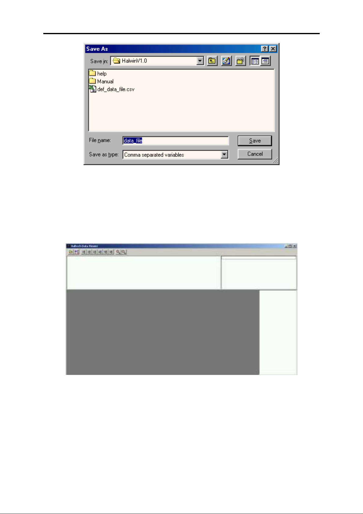
E6GMX Manual
This d ialo g will be f amilia r t o ex pe rien ce d us ers of t he Windows opera ting syst em. Type the
file name that you wish to save your logged data to in the ‘File name’ field. You can choose
which directory to save the file to by clicking on the ‘Save in’ drop down menu. After
selecting your file name, click on the ‘save’ button which will close that window.
9.1.4 Displaying The Data
To open the Haltech Data Viewer, click on the View logged data button on the Data Logging
Options window. Note that this only applicable for the data you have just logged.
Alternatively, you can open the Haltech Data Viewer from the Options->View Data Log
menu. To open a Dataset the user can c lick on File->Open Data File or the user can click on
the folder button on the toolbar. This will open a dialog where the user can select the
appropriate Dataset.
Once you have select ed a Dat aset a nd opened it, you will be presented with a window similar
to t ha t s how n b elo w. The d at a v iewe r will d ispla y th e f irst cha nn el logge d fr om th e Da ta se t
that you have opened.
65
Page 66

E6GMX Manual
9.1.4.1 Displaying Channels
To display one of the channels that you have logged, click on one of the view buttons.
Alternatively the user can press Ctrl 1 to 6 to bring up the appropriate view.
Wh e n a vie w is se le c t e d , a dia lo g will be pre se n t e d whic h allo ws you to select which channels
are to be displayed on each view. To add or remove channels the user can select the
appropriate window (“Available channels” or “Selected channels”) and add or remove
channels using the enter key.
66
Page 67

E6GMX Manual
To adjust the colour or channel properties the user selects the desired channel and can then
select the Channel Colour button or Properties button to adjust the channel colour and ranges.
The P roperties button c ontrols the range of t he view (min and ma x scale), the unit name and
precision. Note if the user wishes to use manual scaling, then min and max numbers selected
must be different. It should be noted that with the exception of colour, HalwinX will save
these settings so they can be reused.
Another method of displaying channels is to double click on c hannels on the right hand side
of the view. As the user selects a Dataset the channels associated with the view appear to the
right hand side of the view. To a dd the channe l to the view the user simply double clicks on
the channel and to remove it from the view the user double clicks on the channel already
loaded. Note displaying t he cha nnels this way implie s that the cha nnels from Data set 1 to 5
are mapped to views 1 to 5 respectively.
9.1.4.2 Changing scales on a View
If the user has multiple scales loaded onto a view then the user can change scales and units by
using the Pg Up and Pg down keys.
9.1.4.3 Viewing Multiple Datasets
The Data Viewer allows you to load more than one Dataset. Each Data set is kept in a separate
file. This allows you to compare the Datasets. The channels from each Dataset can be
accessed by selecting the relevant Dataset from the ‘Loaded Data Sets’ window.
9.1.4.4 Removing A Dataset
To remove a loaded data set, select the ‘Dataset Window’ and select the Dataset you wish to
remove. The ‘Dataset Window’ can be displayed by selecting Data->Show Data Window or
by pressing Ctrl–Alt–D. To remove the selected Dataset, return to the Data Viewer window
and select Data->Remove Dataset or by pressing the ‘Remove Dataset’ button (Next to the
file open button) or by pressing ‘Alt-BkSp’.
67
Page 68

E6GMX Manual
9.1.4.5 Data Values
The Data Values window displays the numerical values of each data trace at the cursor
position. The cursor is displayed as a red line and can be moved with the mouse or by using
the arrow keys.
9.1.4.6 Zooming
The user has a number of options to zoom in and out of the views. The following options are
available to zoom in and out at the cursor:
Zooming In
!
Press the ‘Up A rrow’ key.
!
Click the icon with the mouse pointer
!
Press Ctrl -Al t-I
!
Select Data->Zoo m In from the Data menu.
Zooming Out
!
Press the ‘Down Arrow’ key
!
Click the icon with the mous e pointer
!
Press C trl-Alt-o to zoom all the wa y o ut
!
Select Data->Zoom Out from the Data menu. This will zo om all the way out
Alternatively you can select a section to zoom using the right mouse button. Move the cursor
to the desired position and hold the right mouse button down to select and releases at the end
of the selection. Red dotted lines indicate the region used for zooming. This is illustrated
below.
68
Page 69

E6GMX Manual
9.1.4.7 Changing the Trace Width
To modify the width of the traces the user can select Data->Select Pen Width or the user can
press Ctrl – W. This brings up a dialog where the user can type in the trace width in pixels.
The user applies these changes by selecting enter.
Finally to bring up the text view of the selected information the user can select Data->Select
Pen Width or the user can press Ctrl-Alt-C.
69
Page 70

E6GMX Manual
SECTION4 Inputs & Outputs
The E6GMX ECU has a number of optional inputs and outputs other than the available
injection and ignit ion channels. Please note t hat some of these outputs are c urrently used to
control factory outputs, but can be rewired and/or configured to run other options if required.
These are:
OUTPUTS:
- Idle Speed Control
- Auxiliary Out (Aux Out)
- Digital Output (Digital Out 1-2)
- Pulse Width Modulated Output (PWM 1-4)
Below is a table showing the ECU’s configurable outputs and their factory information.
ECU Output
Digital Out 1 TCC A7
Digital Out 2 Thermo fan C1
PWM Out 1 A/C Control C2
PWM Out 2 4th Gear C7
PWM Out 3 Spare F2
PWM Out 4 Spare F4
Auxiliary Out (Aux Out) Bypass D5
INPUTS:
- O
- Auxiliary In (Aux In)
- Spare A/D
- Trim
Below is a table showing the ECU’s configurable outputs and their factory information
Auxiliary In (Aux In) A/C Request B8
Spare A/D Spare E3
Trim Spare E6
All the inputs and outputs have different functions:
- The Idle Speed control outputs can only be used to drive a stepper motor
- For the Aux Out functions refer to 4.2.5 The In/Out Set-up Page, p35
Closed Loop Control
2
ECU Input
idle control valve.
Factory feature Pin
Factory feature Pin
Output Information
Input Information
70
Page 71

E6GMX Manual
- The Digital Outputs and PWM Outputs are functionally described in the
table below. In some applica tions the Digita l Outputs may be use d for fue l
or ignition and will not b e available.
- The O
Closed Loop Control uses the input signal on the O2 pin for O2
2
corrections only.
- For the Aux In functions refer to 4.2.5 The In/Out Set-up Page, p35
Output Description
General Purpose Outputs
Digital Out 1–2 PWM 1 – 4
Turbo Wastegate NO
Bypass Air Control (BAC) NO
Dual Intake Valve
Torque Converter Control
Thermofan
Intercooler Fan
Shift Light
Aux Fuel Pump
Stall Saver
Staging Signal
Turbo Timer
NOS Switch
Anti-Lag Switch
• •
• •
• •
• •
• •
• •
• •
• •
• •
• •
• •
•
•
For further detail on the operation of the PWM outputs and digital outputs refer to CHAPTER
11 Digital Outputs & PWM Outputs, p77.
71
Page 72

E6GMX Manual
CHAPTER 10 OUTPUT OPTIONS SET-UP
The output options and PWM set-up pages are used to program settings for the output
functions of the ECU in a similar way as the set-up pages are programmed. Refer to 4.1
Using the ECU Set-up Pages, p27.
10.1 Idle Speed Control and O2 Closed Loop Control.
10.1.1 Idle Control
The idle control dialog is accessed by selecting Options->Idle Speed Control. The idle
control dialog has a series of fields common to the 4-wire bipolar stepper motor control and
BAC idle control.
There are ten parameters to be adjusted in the idle speed control:
Enable/Disable
The Idle Speed Control can be switched on or off.
Target Idle Speed
This is the engine speed that the ECU attempts to maintain at idle.
Cold Idle-Up RPM
This speed is added to the Target Speed when the engine temperature is cold.
Start RPM
For a period of around 20 seconds after the engine starts, you can specify an extra
increase in idle rpm. Most factory cars will rev 200-300rpm above the cold idle-up
RP M f or a sma ll t ime whe n t hey ar e fir st t ur ned on. Sett ing t he St art RP M t o 0 will
mean that the engine will rev to the Target Idle Speed + Cold Idle-Up RPM when
turned on and resort back to the Target Idle Speed when warm. If you set the Start
RPM to 200RPM, then the engine will rev to the Target Idle Sp eed + Cold Idle-Up
RPM + 200RP M a nd resort bac k to the Target Idle Spee d + Cold Idle-Up RPM after
20 seconds and then resort back to the Target Idle Speed when warm. Graphically, this
can be represented as:
Target Idle RPM + Cold Idle-Up RPM + Start RPM
RPM
Target Idle RPM + Cold Idle-Up RPM
Target Idle RPM
Engine Cold
Engine Warm
0
20sec
5-10 mins
Time
72
Page 73

E6GMX Manual
Number of Steps
This fie ld con tr ols the n umbe r of s te ps t hat th e id le c ont rol w ill ope ra te ove r. I f you
have a stepper motor that uses say 150 steps, you can either elect to operate the stepper
motor over its entire range of steps by setting the value equal to the max number of
ste ps the moto r will do whic h is 150 in this case, or you can restrict the number of
steps it can move through by making this field lower than 150. By restricting the
number of steps you can change the time response of the Idle Control but can also
af f e c t t he a b ilit y of t h e Id le C on t r ol t o ma in t a in c o n t ro l o f t h e e n gine . This is because
in extreme circumstances the Idle Control may wish to move the stepper motor
through a large number of t urns, but the Number of Ste ps on the stepper motor may
restrict the number of turns the motor ca n physically be permitted to move through,
th u s r e du c in g t h e I dle C o nt r o l’s a bilit y t o c on t r ol t h e e n gine a s it d e sir e s. I t is b e st t o
start with a smaller value around 100 and increase it until the stepper motor
demonstrates that it is capable of bringing the engine to the target idle RPM. If the
va lu e is t o o lo w, t h e st e p pe r mo t or will n o t op e n enough to maintain a consistent idle,
or if it is too high, the stepper motor may actually miss pulses that are sent to it and
therefore it will not operate correctly.
Cold Temperature Limit
This is the te mperature below whic h the engine is defined as be ing cold, and thus the
Cold Idle-Up and Cold Opening Steps would apply.
Cold Min Position
When the engine is c old, you can specify the minimum position the st epper motor will
return to. This is useful in some applications where valves besides the Idle Air Control
Motor can switch extra air flow into the engine that would otherwise confuse the Idle
Control into thinking the engine is behaving in a way which it is not. Start with a large
value around 80-90% and reduce the value as you go. The idea is to move it down
until the engine is idling at such a point where it is close to the target rpm. The target
RPM is used to hold the idle once control of the engine has been established. Cold
Min Po sitio n is use d t o re st rict th e p osit ion o f th e c ont ro lling va lve s o whe n t he Idle
Control wishes to regain control of the engine and bring it down to the target RPM it
actually will be able to. If the values you are using are around 80-90%, the Idle
Co ntr ol will p rob ably not be ab le t o re gain co nt rol of th e en gine an d accurately bring
it down to the target idle RPM. This is why you must start with a large va lue for Cold
Min Position and reduce it until the engine is idling happily at the target RPM.
73
Page 74

E6GMX Manual
Hot Min Position
Exactly the same as for when the engine is cold, except the value is used for when the
engine is hot, that is the temperature is above the Cold Temperature Limit.
Cold Opening position (%)
This is t he op enin g posit ion as a pe rce nt age of whe re t he step pe r moto r will ret urn t o
when it is about to a tte mpt to gain control of the engine . When you hit the throttle the
en gin e will accelerate and when it starts to decelerate again, there will come a po int
during the deceleration when the Idle Control should atte mpt to regain control of the
engine and bring it to the target idle RPM. The value you set here will res ult in th e
stepper motor assuming a certain position, say 40% out. It will wait here until the
decelerating engine comes within range and it feels it can take over control of the
engine and bring it back to idle. It will then assume control of the engine with the
va lve ope n a t 40 %. Th is may be too high whic h will resu lt in the engine moment ar ily
holding at the RPM p roduce d by t he valve a t 40% open ing. This me ans t hat it will
take a longer period of time to move the engine back down to target idle.
On the other hand, 40% may be too low and when the engine is decelerating, the Idle
Control will try to regain control at a point where the valve is going to cause the
en gine t o go v e r y c lo se t o st a llin g. Th e se c r e t is t o st a r t wit h a la r ge v a lu e a nd r e du c e
it until it takes a normal amount of time for the idle control to regain control of the
decelerating engine and bring it back to target idle. A normal amount of time is a hazy
description but it is somewhere in the vicinity of not too small so as to go close to
stalling the engine and not too large as to take many seconds to return to target idle.
Hot Opening Position (%)
Exactly the same as for when the engine is cold, except the value is used for when the
engine is hot, that is the temperature is above the Cold Temperature Limit.
10.1.2 O2 Closed Loop Fuel Control
The O2 closed loop dialog is accessed by selecting Options -> Closed Loop O2. The dialog
has a series of fields that require configuration:
Lower RPM Limit
The engine must be running a bove this speed for the closed loop function to ope rate.
Normally this would be set a few hundred rpm above or below idle, depending on
whether you wish closed loop control to occur at idle speeds.
Upper Throttle Limit
It is genera lly undesirable to run an e ngine at stoichiometric air-fuel ratio when under
load. This parameter is used to determine when the driver is demanding sufficient
engine output to disengage the closed loop function. The smaller this number, the
earlier the feedback control will drop out.
Engine Cycles Between Corrections
The oxygen sensor does not respond immediately to the exhaust gases of the
combustion which has just taken place. There is a gas transportation time from the
engine to the sensor, plus the sensor reaction time itself. Consequently, the ECU
counts a number of engine cycles before accepting the reading from the oxygen
74
Page 75

E6GMX Manual
sensor. If the closed loop function is re sponding erratically, constantly overdriving t o
th e ad just ment limit s, or if th er e is insu ffic ien t os cilla tion in t he a ir-fuel ratio for the
cata lytic conve rter t o operat e, increasing this pa rameter may help. If it is set too high,
the feedback loop will be noticeably slow to respond to change.
O2 Sensor Threshold Voltage
This is the sensor voltage by which the E6GMX determines whethe r the engine is lean
or rich; it is the target that is sought to be maintained. This is normally set to the
voltage that corresponds to an a ir-fuel ra tio of 14.7:1, t he NGK he a te d 4 -wire sen sor
threshold voltage is around 600mV this va lue will vary f or d if fe r e n t se n so rs . I t is a ls o
known as the sensors reference voltage.
Maximum Fuel Increase
The closed loop algorithm will be permitted to increase the fuel injection time no
further than this limit while attempting to enrich the mixture. The valid range for this
limit is 5% to 12.5%.
Maximum Fuel Decrease
Again a range of 5% to 12.5% applies to this parameter which is the limit of correction
permitted to the base fuel injection time when leaning the mix.
Note: It is preferable to keep the increase and decrease limits small (say around
5-10%). Excessive swinging of the air-fuel ratio can result in surging and poor
operation of the catalytic converter. The closed loop algorithm should never be
used as means to correct bad mapping.
Engine Cycles at Idle
Exhaust gas transportation time is much higher at idle, when the engine is breathing
the least. If running the closed loop at idle, a longer time must be allowed to pass
before performing a feedback correction response.
O2 Sensor Threshold at Idle
It is unlik ely t ha t the e ngine will ru n a t idle smoo th ly at th e sa me a ir-fuel ratio as at
cruise. Typically, a richer mix is necessary. This parameter allows a different
threshold voltage to be targeted during closed loop correction at idle.
O2 Sensor Type
The type of sensor used should be selected here. Choose the sensor tha t best describes
the sensor you are using. It is a lso possible to at tac h a 5 Volt sensor, such as a UEGO
probe, to the E6GMX. Since these sensors are expensive, and have limited life, it is
unlikely that they would be used in general running of the car for closed loop feedback
control, but rather as an aid during tuning.
75
Page 76

E6GMX Manual
10.2 The PWM Options Page
The PWM options page contains the set-up information for the four PWM (pulse width
modulation) output s and the Digital output options. The PWM options page is accessed via
the options menu or using: CTRL-O from anywhere in the programming software.
The PWM output window contents change depending on the function it is to perform. A
comprehensive description of these functions can be found in CHAPTER 11 Digi tal Output s
& PWM Outputs, p77.
To change the PWM output function select the required parameter from the drop down box.
Wh en the use r c lick s on t he Pr ope rt ies b ut ton th e pa ra met er s pert ain ing to th at fun ct ion will
be displayed. Once the desired properties have been entered the user click on the Apply or OK
button, or they hit the ente r key. Note this has to be done for both t he P WM options and the
properties.
PWM Output Options page
76
Page 77

E6GMX Manual
CHAPTER 11 DIGITAL OUTPUTS & PWM OUTPUTS
The digital outputs and PWM outputs can be programmed to operate a wide variety of
functions. Some of the functions have restrictions to their operation.
Below is a table showing the ECU’s configurable outputs and their factory information.
ECU Output
Digital Out 1 TCC A7
Digital Out 2 Thermo fan C1
PWM Out 1 A/C Control C2
PWM Out 2 4th Gear C7
PWM Out 3 Spare F2
PWM Out 4 Spare F4
Auxiliary Out (Aux Out) Bypass D5
The functions and their restrictions are described in the table below:
Output Description Digital Out 1–2 PWM 1 – 4 Max #
Turbo Wastegate N/A
Bypass Air Control (BAC) N/A
Dual Intake Valve
Torque Converter Control
Thermofan
Intercooler Fan
Shift Light
Aux Fuel Pump
Stall Saver
Staging Signal
Turbo Timer
NOS Switch
Anti-Lag Switch
BAC2 N/A PWM 3 & 4 1
BAC2/BAC Slave N/A PWM 3 & 4 1
TPS Switch
For installation information regarding any hardware associated with the described output
functions refer to CHAPTER 1 Haltech ECU Installation, p11.
Each individual function and its parameters are described below.
Factory feature Pin
• •
• •
• •
• •
• •
• •
• •
• •
• •
• •
• •
• •
Output Information
•
•
2
1
Unrestricted
1
Unrestricted
Unrestricted
Unrestricted
Unrestricted
1
Unrestricted
1
1
1
Unrestricted
77
Page 78

E6GMX Manual
11.1 Turbo Waste Gate Control (TWG)
The turbo waste-gate control function controls a solenoid tha t ble eds a ir from the waste-gate
diaphragm preventing the waste-gate from opening.
Period 1 – 50 ms
This sets the period of oscillation of the solenoid. Most
sole noids will operat e at around 30Hz, which corresponds to a
period of about 30ms. Enter the desired oscillation period in
milliseconds here.
Use Map One or Two or Advanced
There are two maps associated with the TWG control function.
Both set the duty cycle driving the solenoid versus engine rpm.
This p a r a me t e r s e le c t s wh ic h ma p t h e E C U will use t o d riv e th e
bleed solenoid.
“One” and “Two” refer to the waste-gate maps one and two
respectively. The “advanced” option refers to conditional use
of map one and map two. The conditions for waste-gate map
usage when “Advanced” is selected are:
If the ECU is using the primary fuel and ignition maps then the
EC U will use wast e- gat e ma p one t o co ntr ol boost. If the ECU
is using the secondary fue l and ignition maps then the ECU will
use waste-gate map two to control boost. Refer to 4.2.1, Mai n
Set-up Page p35.
Boost Limit 0 – 209kPa / 0 – 30 psi
If the manifold pressure exceeds this limit, the solenoid valve
will imme dia t e ly b e se t wit h a d ut y c y c le va lu e o f 5 % . Th is will
expose the waste-gate diaphragm to the full manifold pressure
and force the waste-gate to open. This value should be set
slightly higher than the desired maximum boost pressure as a
fail-safe in the event of an over-boost condition.
Update Eng. Data ENABLED or DISABLED
This field defines whether the duty cycle being used to drive the
solenoid is displayed in the engine data page.
11.2 Bypass Air Control (BAC) Valve
The bypass air control func tion controls a solenoid that regulates air around the throttle to
control the idle speed of the engine. This option has only one parameter:
Period 1 – 50 ms
This sets the period of oscillation of the solenoid. BAC
sole no ids will o per at e a cr oss a ra nge o f fr equ en cie s. E nte r th e
desired oscillation period in milliseconds here.
The remaining parameters for idle control can be found in the output options page and are
described in 10.1.1 Idle Control, p72.
78
Page 79

E6GMX Manual
11.3 Dual Intake Valve Control (DIV)
Some late model engines possess two tuned intake manifolds. One intake tract remains shut at
lower rpm where there is less airflow, then opens as airflow demands increase. This provides
a broader torque curve. The DIV function controls the solenoid that operates this valve.
Switch On RPM 0 – 16000 RPM
This is the engine speed at which the solenoid is to be
energised.
Switch Off RPM 0 – 16000 RPM
This is the engine speed at which the solenoid is to be deenergised.
There are two configurations in which this feature can be used:
The first configuration is to have two engine speed ranges; one high and one low. In the
lower range the solenoid is disabled and in the upper range the solenoid is enabled. Using this
configuration the On RPM should be set to the lower RPM limit of the upper range and the
Off RPM should be set to at least 200 RPM below On RPM, forcing hysteresis in the
switching to prevent the solenoid from oscillating when the engine speed is at the switch
point.
The second c onfiguration is to e nable the solenoid for a range of engine speed and t o disable
the solenoid when the e ngine speed falls outside this range . To do this the On RPM is se t to
the lower RPM limit of the range and the Off RPM is set at the upper RP M limit, when the
RPM is lower than On RPM the solenoid is disabled, when the RPM is greater than On RPM
but less than Off RPM the solenoid is enabled, when the engine speed is greater than On RPM
and Off RPM then the solenoid is disabled.
11.4 Torque Converter Clutch Lockup (TCC)
This function controls the clutch lockup solenoid on automatic transmissions. The function
has no control parameters and is simply enabled or disabled. This function is used in
conjunction with the torque converter clutch lockup map - refer to 4.5.8 Torque Conver ter
Control Map, p48 - and the Aux. In function - refer to 4.2.5 The In/Out Set-up Page, p35.
11.5 Electric Thermo Fan Control (TF)
This function can be used to switch a thermo-fan on when the engine temperature exceeds a
certain value. The fan will stay on until the engine temperature drops sufficiently.
Switch On Temp. 0 – 127 °C / 32 - 261 °F
The temperature the engine coolant must exceed to switch the
fan on.
Switch Off Temp. 0 – 127 °C / 32 - 261 °F
The te mperature be low which the coolant must drop before the
fa n will b e swit c h e d of f . Th is p a r a me t e r should be around 3-5°
79
Page 80

E6GMX Manual
lower than the “Switch On temperature” to prevent the fan from
switching in and out repeatedly.
11.6 Electric Intercooler Fan Control (IF)
This function can be used to switch an intercooler fan on when the intake-air temperature
exceeds a certain value. The fan will stay on until the engine temperature drops sufficiently.
Switch On Temp. 0 – 127 °C / 32 - 261 °F
The temperature the intake-air must exceed to switch the fan on.
Switch Off Temp. 0 – 127 °C / 32 - 261 °F
The temperature below which the intake-air must drop before
th e fa n w ill be s witc he d of f. Th is pa rame te r should be around
3-5° lower than the “ Switch On temp.” to prevent the fan from
switching in and out repeatedly.
80
Page 81

E6GMX Manual
11.7 Shift Light Illumination (SL)
This function can be used to drive a light or buzzer to indicate the engine speed exceeds a
programmed level.
Light On RPM 0 – 16000 RPM
This parameter sets the engine speed at which the output will be
enabled.
11.8 Auxiliary Fuel Pump (AP)
This function causes the output to turn on when the measured engine load or engine speed
exceed the programmed values. The output remains on while these conditions are met and for
the programmable period of time after which the conditions are no longer valid.
Load Bar Bar 1 – 32
This is the bar number on the fuel maps which must be
exceeded for the extra fuel pump to be switched on. If you wish
to switch the extra fuel pump only by engine speed, set this to 0.
Engine Speed 0 – 16000 RPM
The extra fuel pump will turn on when the engine speed
exceeds this parameter. If you wish t o switch the pump only by
load, set this parameter to 0 rpm.
Run Time 0 – 70 s
The a u xilia r y fu e l p ump will s wit c h on if the en gine ex ceeds the
engine speed and/or t he load bar set a bove. It will t h e n s t a y o n ,
even aft er speed and load have dropped be low t heir respective
limits, for a period of time specifie d by Run Time. A minimum
Run Time of 5 seconds is permitted.
The Aux iliary Fue l Pu mp will p rime w ith t he main fue l pump , bu t will o nly r un if the a bove
conditions are met. Since t here may be a short delay from the time the fuel pump is switche d
on to the t ime the extra fuel becomes available, the Load Bar and Engine Speed settings above
should be set to enable the auxiliary fuel pump before the primary pump runs out of flow.
11.9 Anti-Stall Solenoid Control (AS)
A solenoid air valve in the manifold may be used to allow extra air into the engine during
cranking or extremely low rpm. This can aid in starting the engine, or in preventing it from
stalling if engine revs drop too low.
Lower RPM Limit 0 – 16000 RPM
This parameter defines the engine speed at which the output
will turn on.
81
Page 82

E6GMX Manual
11.10 Turbo Timer (TT)
The turbo timer function allows the E CU to continue running the engine after the ignition has
been switched off. This function allows the engine to idle until the coolant and air
temperature have fallen below programmable values or a programmable period of time has
elapsed. The output is turned on until the programmed conditions are met. This output is
used in conjunction with the Aux In. line. Refer to 4.2.3 Ignition Set-up Page, p32.
Air Temp 0 – 127 °C / 32 - 261 °F
This para meter defines the t emperature below which int ake-air
must fall before the output will be turned off.
Coolant Temp 0 – 127 °C / 32 - 261 °F
This parameter defines the temperature below which coolant
must fall before the output will be turned off.
Run Time 0 – 5 mins
This para meter defines the maximum time for which the output
will remain on regardless of the temperature parameters.
11.11 NOS Switch
This function controls the operation of a NOS system.
Note:
It does not control the delivery of the Nitrous Oxide, but simply turns the
system on or off in certain conditions. The NOS system must control the
delivery of the nitrous oxide and must also provide extra fuel delivery.
A swit c h c o nn e c t e d t o t h e Au x ilia ry I nput ena bles the output. Once enabled, if the conditions
sta t ed b elo w ar e me t, t he NOS syst em w ill be a ct iva te d. Th e Aux iliary Input Function in the
Identification must be set to NOS Switch for the function to operate correctly.
Load Bar Bar 1 – 32
If the Fuel Map Bar Number exceeds this value, the NOS
syst e m will b e t urn ed o ff. This is u sed for tu rbo engin es wh er e
the NOS is used to help boost the turbo. Once on boost, the
NOS can be turned off. Normally aspirated engines, on the
other hand, c an use NOS at full load, so this va lue should be set
to bar 32.
Max. Rpm 100 – 16000 RPM
If the RPM exceeds this value the NOS system will be switched
off.
Min. Rpm 100 – 16000 RPM
If the RPM is below this value the NOS system will not be
activated.
Minimum Throttle 0 – 100 %
The NOS system will be turned on above this value.
Minimum Temp 0 – 127 °C / 32 - 261 °F
The NO S syst e m w ill no t b e a c t iva t e d u nle s s t h e e ngin e c oo la n t
temperature is above this value.
82
Page 83

E6GMX Manual
Ignition Retard 0 – 20 °BTDC
The ECU will provide an ignition retard whenever the NOS
system is engaged.
Start-up Delay 0 – 120 s
The ECU will prevent t he NOS syste m operating r egard less of
the above conditions until the period of time programmed in
this field has elapsed.
11.12 Anti-Lag Switch
WARNING:
DO NOT OPERATE ANTI-LAG FOR PROLONGED PERIODS.
EXHAUST AND TURBO TEMPERTAURES RISE, WHICH MAY
CAUSE ENGINE DAMAGE.
The Anti-Lag switch function allows turbo-charged vehicles to decrease the “lag” associated
with boost when the motor is not under full load.
Retard Value 0 – 70 °BTDC
The ignition timing is retarded by this angle when the Anti-Lag
conditions for operation are met.
% Inc. Fuel 1 – 50 %
The percentage of fuel increased during Anti-Lag operation.
Zero TPS ONLY ON or OFF
If the Anti-Lag function is to be used when the Throttle Position
Sensor value is zero then turn this function ON.
Zero Inj Time 1 – 16 ms
If the zero TPS only func tion is ON then this value determines
the amount of fuel injected at zero or no throttle. The valid
range is (1-16) ms.
Throttle Perc. 5 – 80 %
The throttle position value below which Anti-Lag is
operational. The valid range is (5-80)%.
On RPM 100 – 16000 RPM
This field specifies the RPM above which Anti-Lag is
operational.
On Coolant Temp 0 – 127 °C / 32 - 261 °F
This field defines the coolant temperature above which AntiLag is operational
The anti-lag system is can be enabled by a switch connected to Aux. In or by meeting all three
operating conditions stated above (the last 3 fields). Once the switch is enabled, if the
Throttle condition is met, the anti-lag system will b e a c t iva t e d . The la s t t wo fie ld s a llo w t h e
ALS to be ac tivated when all three conditions are met regardless of t he AUX In setting; this
allows the AUX In to be used for another purpose.
83
Page 84

E6GMX Manual
11.13 Air Conditioning
The Air conditioning function allows the ECU to intercept the vehicles Air Conditioning
request and grant or refuse the request based on the current operating conditions.
Throttle Pos. 5 – 100 %
This field defines the throttle position above which the Air
conditioning request is disabled. This condition is independent
of any other fields.
Engine Speed RPM 1000 – 15000 RPM
This field defines the engine speed above which the Air
conditioning request is disabled. This condition is independent
of any other fields.
Off Time (s) 0 – 70 s
This field defines a delay after which an Air conditioning
re q ue s t will b e a llow e d o n c e the above conditions fall below the
set values.
Active AUX In. HIGH or LOW
This field defines the active state of the Air conditioning request
line installed in your vehicle. If the line is active high this
means that the signal on the line when an Air conditioning
request is made is ~5 volts and when the line is idle the voltage
is ~0 volts. If the line is active low this means the Air
conditioning request is ~0 volts and the idle line is ~5 volts
(refer to 4.2.5 The In/Out Set-up Page, p35).
11.14 Engine Control Relay
This fe ature causes the ECU to turn on t he output when the E CU has power. This input can
be used to drive a relay that supplies power to the engine bay.
This input has no parameters.
84
Page 85

E6GMX Manual
11.15 VTEC
This func tion controls the solenoid used to control the variable valve timing with whic h some
engines are equipped. This feature acts purely to control a switching solenoid and is not
capable of controlling continuously variable valve timing.
On RPM 0 – 16000 RPM
This field defines the engine speed above which the VTEC is
en ab led. This f ield mu st b e gre at er th an O ff R PM o r it will be
ignored.
Off RPM 0 – 16000 RPM
This field defines the engine speed below which the VTEC is
disa b le d . Th is f ie ld mus t b e le s s t h a n O ff R P M o r it will d e fin e
both the switch on and switch off RPM forcing the ECU to
ignore On RPM.
On Load Bar Bar 1 - 32
This field defines the engine speed above which the VTEC is
en a b le d. Th is f ie ld mu st b e gre a t e r t h a n O ff L o a d B a r or it will
be ignored.
Off Load Bar Bar 1 - 32
This field defines the engine load below which the VTEC is
disa bled. This field mu st be less t han Off L oad Bar or it will
define bot h the switch on and switch off Load forcing the ECU
to ignore On Load Bar.
The above Load a nd RPM conditions that cont rol the VTE C function are independe nt of one
an ot her an d will swit ch th e VTEC on if eit her On lo ad o r On RP M conditions are met. The
function will turn VTEC off when both Off Load and Off RPM conditions are met.
Off RPM should be set to at least 200 RPM below On RPM, forcing hysteresis in the
swit c h ing t o pr e v e nt t h e so le n oid f ro m o sc illa t in g. Th e sa me sw it c hin g gap should be applied
to Off Load Bar and on Load Bar.
11.16 BAC2
Open Loop idle control is an alternative to closed loop idle control offered in the Output
Options page . This met hod of control is easier to tune but less accurate and may result in the
idle speed drifting from the set point by ~100rpm. The control looks at a set of engine
conditions and drives the BAC valve with a duty cycle programmed by the user based on
these conditions. This function supports the “BAC2 Idle” trim function (refer to 4.2.5 The
In/Out Se t-up P age, p35) , w hic h o ve r r ide s a ll t he p a r a me t e rs be lo w if it is e n ga ged . The id le
trim is designed as a tuning aid rather than a full time idle control solution.
The following user programmable parameters det ermine the period and duty cycle applied to
the BAC Valve:
Period (ms) 1 – 51 ms
This defines the period of the signal used to drive the BAC
valve.
85
Page 86

E6GMX Manual
Cold Idle Temp. 0 – 127 °C / 32 - 261 °F
This value is the coolant temperature above which the “hot”
base duty cyc le value is used and below which t he “cold” base
duty cycle will be used.
Cold Duty: 0 – 100 %
This is the base duty cycle used when the coolant temperature is
below the Cold Idle Temp value.
Hot Duty: 0 – 100 %
This is the base dut y cycle used when the coolant temp is above
the Cold Idle Temp value.
A/C Load Duty: 0 – 100 %
This is a duty value added to the current duty cycle to increase
the opening size to compensate for the load change associated
with the A/C compressor. This is enabled when the A/C makes
a request. (Aux. In must be selected a s A/C request. Refer to
4.2.5 The In/Out Set-up Page, p35).
Start-Up Duty: 0 – 100 %
This is a duty value added to the current base value and any
other additions to make the total duty cycle. This is enabled
during the first 20 seconds after the engine has started.
Active (Aux In): HIGH or LOW
This is the Active signal level received from the A/C line when
it is making a request (opposite of idle position).
11.17 BAC/BAC2 Slave (Bipolar idle valves)
The BAC/BAC2 Slave offers the extra control signal required for Bipolar BAC Valve. This
function is used in conjunction with the “ BAC Valve” and “ BAC2” PWM functions. This
signal is the inverse of the primary signal produced by the BAC or BAC2 PWM channel.
Slave Channel PWM3 or PWM4
This parameter defines the channel from which the Slave is
driven. If the only option is “None” then there are no PWM
functions selected that support “BAC/BAC2 Slave”. The
options in this list are limited to the PWM channels that are set
with valid BAC/BAC2 Slave functions.
11.18 TPS Switch
The TPS switch output switched based on the current throttle position.
Switch On 0 – 100 %
This is the throttle position at which the output produces and
active level.
Switch Off 0 – 100 %
This is the throttle position at which the output produces and inactive level.
86
Page 87

E6GMX Manual
Active Sw. Posn. HIGH or LOW
This de fines the act ive level or polarity of t he signal. When this
field is set to HIGH the active output is 12V, when the field is
set to LOW the active output is 0V.
There are two possible configurations for this feature:
The first configuration is to have two thrott le position ranges; one high and one low. In the
lower range the output is inactive and in the upper range the solenoid is active. Using this
configuration the “Switch On” field should be set to the throttle position limit of the upper
range and t he “ Switch Off” should be set about 5% below “Switch On”, forcing hystere sis in
the switching to prevent the output from oscillating around the switch point.
The second configuration is to set t he output in the act ive state for a range of throttle position
and to set the output inactive outside this range. To do this the “Switch On” is set to the
lower throttle limit of the range and the “Switch Off” is set at the uppe r throttle limit, when
the throttle position is lower than “Switch On” the solenoid is disabled, when the throttle
position is grea ter t han “ Switch On” but less than “Swit ch Off” the solenoid is enabled, when
the throttle position is greater than “Switch On” and “Switch Off” then the solenoid is
disabled.
87
Page 88

E6GMX Manual
SECTION 5 Appendices
APPENDIX A TROUBLESHOOTING
This Appendix is devoted to trouble shooting proble ms that may occur during installation and
configuration of the ECU. To use this Appendix, ide ntify the symptom or symptoms that best
describe the problem from the list below, then follow the checklist for possible solutions.
Control Program Problems
• The Haltech Programming Software will not start
• The Haltech Programming Software will not operate in ONLINE mode.
• The Engine Data Page is displaying unusual sensor readings
Starting Problems
• Fuel Pump does not prime when ignition switched on.
• The engine makes no attempt to start
Idling P roblems
• The engine will not idle when cold
• The engine idles too slow
• The engine idles too fast
• The engine surges at idle
Light Throttle and Cruising Problems
• Engine will no t run at light throttle
Full Power Problems
• Engine dies under full throttle
• Engine surges under full throttle
• Engine lacks power at full throttle
Throttle Response Problems
• Poor throttle response
• Poor throttle response when cold
Cold running problems
• Engine runs poorly when cold
Fuel Economy problems
• Poor fuel economy - city cycle
• Poor fuel economy - Highway cycle
88
Page 89

E6GMX Manual
A.1 Control Program Problems
Haltech Programming Software will not start
The Haltech programming software should run on a ny computer that me ets the re quirements
ou t line d in 2.1 Computer Requi re ments, p13. If for an y reason the programming software will
not start up reinstall the software and double check the computer specifications.
Haltech programming software will not run ONLINE
If the Haltech ECU does not respond to the P rogramming software requesting information,
then the message HALTECH DISCONNECTED will b e displa ye d. This situ at ion will o cc ur
under the following conditions
ECU is not powered up
Programming Cable is not connected
Incorrect COM port selected
Wrong Programming Software
Programming Cable is damaged
Serial port of programming computer is faulty.
If the software is the wrong version or you suspect that the cable is faulty, contact your
Haltech dealer.
Engine Data Page Displays Unusual Readings
If the air temperat ure sensor, or coolant te mperature sensor is showing a continuos maximum
or minimum then the sensors are either not operating correctly or are disconnected. Using the
wiring diagram of the E CU Loom (wiring diagram can be found at the back of this manual)
check that the sensor wires are not damaged. Check for continuity or high resistance with a
multimeter. If the wiring is OK then contact your Haltech dealer regarding replacement of
faulty sensor.
If the Throttle Position Se nsor is unresponsive or is erra tic then re-calibrate the throttle sensor
and check the wiring. Erratic readings can be caused by damaged sensor or electrical noise.
If the Manifold Absolute Pressure Sensor does not read near atmospheric pressure with the
engine off, or if it shows a fault condition, t hen check that the se nsor is connected correctly.
Check that you have the correct model sensor and that the Identification page information has
been set correctly.
If the Engine Speed reading is erratic, the trigger (crank or cam signal) is most likely picking
up ignition noise from incorrect plugs or leads, electrical noise from cooling fans, starter
motor, alternator or other electrical devices in the vehicle. Ensure that the trigger signal wire
is properly shielded and that the shield is not grounded at the sensor end.
If the Engine Speed is steady but wrong, check that the Identification page contains the
correct information regarding number of cylinders, crank sensor set-up and crank sensor
wiring is correct.
If e ngine parameters are a ll showing unusual variation, ma ke sure that the ECU is grounded
properly. Also check the engine and chassis grounds to the battery.
89
Page 90

E6GMX Manual
A.3 Starting problems
Fuel Pump doesn't prime when ignition switched on
The Haltech E6GMX will attempt to run the Fuel pump for about 2 seconds just after the
ignition is switched on. The fuel pump relay should be hea rd clicking in and out with the fuel
pump.
Engine makes no attempt to start
Check the following:
Does the engine run with the Standard ECU
ECU is operating (will communicate ONLINE) during cranking
Battery voltage and connections
Fuel Pump runs
Injector fuse is OK and injectors fire
Ignition system is operating properly and spark is available
Ignition timing is correct
If the engine is flooding, reduce the bars in the fuel map that are being used during c ranking
in the fuel map, the coolant correction map and the cold prime map.
If the engine is not receiving enough fuel and increasing those bars does not help, chec k that
fuel pressure is available and that the injectors operate properly (are cleaned and flow-tested).
A.4 Idling Problems
If the engine will not idle when cold but will when the engine is warm then the coolant
correction map may need to be adjusted.
If the engine idles too fast or too slow, and you are using an Idle Air Control Motor, firstly
check that the Idle Speed Control is enabled, and then lower the target idle setting if
necessary. If not using the idle air control motor then adjust the idle using the idle adjust
screw on the throttle body. Check for any air leaks in the manifold.
Check the ignition timing at idle and adjust if necessary.
If the engine surges or hunts at idle then the mixtures and timing are wrong. Adjust the fuel
maps near idle conditions.
In some circumstances it may be necessary to use the Zero Throttle Map. Consult Chapter 6
[6.2] for information on using the Zero Throttle Map.
A.5 Light throttle and Cruising Problems
If the engine falters under light load then the mixtures may be incorrect, check the Fuel Maps.
90
Page 91

E6GMX Manual
A.6 Full Power Problems
If the engine gasps under full throttle then the mixture may be too lean. If the engine bogs
down and blows smoke then the mixture is rich. Recheck t he fuel maps.
If the maps appear to be correct then ensure that the fuel pressure is not falling out of
regulation by using a fuel pressure gauge. Flow test and clean the fuel injectors.
In some circumstances it may be necessary to use the Full Throttle Map. Consult Chapter 6
[6.3] for information on using the Full Throttle Map.
A.7 Throttle Response Problems
Throttle response of the E6GMX is set using the three pairs of throttle pump settings. If t he
engine gasps and flat spots (misfires) when the throttle is suddenly opened then the throttle
setting is not high enough or is much too high. If the engine bogs down but continues to run
then the mixture is too rich. Experiment with the throttle pump settings to achieve the
optimum.
The throttle pump coolant factor affects the throttle pump only when coolant correction is
being applied, i.e. before the engine has reached operating temperature. Set the throttle pump
increase and sustain figures only when the engine is warm. Wait until the engine is cold again,
and the coolant correction map has been set for good stable running, before changing the
coolant factor.
A.8 Cold Running Problems
If the engine idle s poorly when cold then the coolant map may ne ed adjusting. If the engine is
hunting slightly when cold, then the coolant correction map is just too lean, and so needs a
small amount of enrichment. Slight advanc e with the coolant temp. can help. If the engine is
difficult to drive when cold, particularly with gear changes, try increasing the coolant
correction factor for the throttle pump.
An en gine th at will idle whe n wa rm, b ut fails to id le c old u nle ss a t iny amount of throt tle is
applied may require idle speed c ontrol, with a fast-idle function for when the engine is cold.
The E6GMX can control an Idle Air Control motor that will perform this function.
A.9 Fuel Consumption
Poor fuel consumption is a result of a too rich mixt ure. If the fuel consumption in t raffic is
poor but the highway consumption is good, then it could be the areas of the map used for
accelerating that need to be leaned out. The throttle pump may also waste fuel if its values are
too high. Also try using the fuel cut off on deceleration feature.
If the city consumption is fair but highway c ruising uses too much fuel then lean out t he light
load bars on the 2000 rpm to 3000 rpm maps (This is where most cruising takes place).
If the cold start map is supplying too much fuel on warm-up this will also affect the fuel
consumption of the vehicle.
91
Page 92

E6GMX Manual
APPENDIX B IGNITION AND INJECTION OUTPUTS
Ignition
The simplest of ignition systems is the distributed setup. The distributor uses a rotor button
and cap to distribute the spark to the correct cylinder. In most cases the distributor will
contain a triggering device use d to trigger an ECU or an ignition module directly.
Rotor phasing (GM Bypass Ignition module)
If the engine is currently fitted with a GM Bypass Ignition Module the Rotor phasing ca n be
checked quite easily. The first thing to do is to remove the ECU, so that neither the standard
ECU nor the E6GMX is conne cted. Crank the engine . The Ignition module has the a bility t o
fire the ignition without the ECU being connected. The Ignition module will fire where it
believes is 10 deg BTDC. If the spark timing is not at 10 deg BTDC, move the distributor
until it is firing at 10 deg BTDC. Lock the distributor and do not move again. Plug in the
E6GMX.
Rotor phasing (No GM Bypass Ignition module)
A common problem that arises whe n distributors are used is cross-firing. This usually occurs
when the rotor button is not in the correct position when the ignition output is fired. To
correctly set up the distributors “Rotor Phasing” you will need to do the following:
Calculate the minimum and maximum timing requirements of the engine. For this example
we will use the following:
Minimum Timing 10° BTDC
Maximum Timing 40° BTDC
This gives a mid point, half way betwe en the minimum and maximum timing, of 25°. Rota te
the engine to this value (25°) BTDC. Align the centre of the rotor button with the plug lead
terminal for cylinder number one. Lock the distributor into place and do not move it.
Now rotate the engine to 70° BTDC. i.e. move it back 45° crank
po sit io n w he r e t h e se n so r in sid e t h e dis t rib u t or will n e e d t o b e a ligne d wit h a t r igger ing p oin t .
(This may be a magnetic sensor t ooth, or a c hopper disc window). Move the plate t he sensor
is mounted on so that this occurs (Do not rotate the engine!).
If it is n ot p o ssib le t o mov e t h e se n so r, it will b e n ecessary to rotate the trigger wheel relative
to the shaft and the sensor.
Rotor phasing is not only a problem on distributors with advance mechanisms. Several factory
distributors have the ir triggers at points outside 60 - 100°. It is not advisable to just rotate the
distributor unt il the trigger is within this window. Care must be take n to ensure t hat t he rotor
phasing will not cause a problem.
degrees. This is now the
92
Page 93

E6GMX Manual
70%
B.7 Ignition Outputs
The ignition outputs of the ECU are designed to provide the appropriate signal to drive an
ignitor. The ECU is capable of driving either smart (Constant duty) or dumb (Constant
charge) ignitors.
WARNING:
UNDER NO CIRCUMSTANCES SHOUL D THE IGNITION OUTPUTS
OF THE ECU BE USED TO DRIVE THE COILS DIRECTLY. THE
IGNITION OUTPUTS OF THE ECU ARE INCAPABLE OF SINKING
SUFFICIENT CURRENT TO GENERATE SPARK AND WILL
SIMPLY FORCE THE IGNITION DRIVERS INTO SHUTDOWN
Constant Duty
Co nst ant Dut y ignit or s co nta in c irc uitr y t hat will op timise th e d well f or th e nex t ignitio n and
consequently the ECU only needs to provide a signal that has a constant duty cycle and a
timed edge for ignition. A constant duty ignition signal will appear as below:
The function of the Ignition Module is to trigger the Ignition Coil through the Power
Transistor, which is part of the Ignition Module. There are two main types of ignition
module Constant Dwell and Constant Charge Modules. The Constant Dwell Module (smart)
internally determines coil charge (dwell) time. The ECU therefore triggers the ignition
module using a constant duty cycle with respect to the engine spe ed (this waveform is
equivalent to the output of a points ignition).
+12V
GND
+12V
Duty
Cycle
30%
Duty cycle remains constant as RPM increases
Duty Cycle
30%
70%
Low RPM
High RPM
Time
GND
Time
93
Page 94

E6GMX Manual
Constant Charge
The Constant Charge Module (dumb) charges the Ignition Coil with a constant charge time
no matter what RPM the engine is doing. Dumb Igniters require the ECU to perform the
dwell control or charge time of the ignition coils. The signal from the ECU determines the
charge time of the coil and tries to maintain a constant charge time at all engine speed where
possible.
The coil’s charge time can be determined from the coil negative signal: when the coil
switches on, the coil negative voltage drops to zero, as the coil energises the voltage rises
slightly until a sharp rise where the ignitor current has reached the upper limit. When the
current ceases to increase the coil has maximum energy and any more energy applied by
lea v in g it s wit c h e d o n will b e wa st e d a s h e a t . It is a t t his po in t t ha t t h e c o il is sw it c h o f f a n d
the coil is fired.
.
For a dumb igniter with a falling edge spark edge, with 4ms of coil charge time, the ECU
ignition output waveform will look like the following waveform
+12V
GND
+12V
GND
4ms
Charge
time
Low RPM
Charge time remains constant as RPM rises
4ms
Charge
time
High RPM
Time
Time
Warning:
Never send a constant duty cycle waveform to a Dumb Ignition Module. Using a constant
duty cycle signal on a dumb ignition module may cause the ignition coils to be damaged
from overcharging. Ignition modules may also be damaged as a consequence.
94
Page 95

E6GMX Manual
The majority of modern ignition modules are the Constant Charge type with inbuilt current
control. Current control limits the primary current to avoid damage to ignition components,
primarily t he Ignition Coil. The primary current charge time is read in milliseconds and is
controlled by the coil charge time field. The primary charge time will usually vary between
1.4 ms and >4 ms (some older systems may be up to 8.7ms) depending on the vehicle
manufacturer and ignition system used.
Coil Charge time
The following is a guide to primary charge time and spark duration time for different
coil charge times.
Coil Type Typical Charge time
Single Standard Coil 2.5 ms
Single Fast Charge Coil 2 ms
95
Page 96

E6GMX Manual
Spark
Output
Mode
Setting
Ignition Setup page showing Spark Output mode Setup
96
Page 97

E6GMX Manual
Ignition Spark Edge
The ignition “Spark Edge” in the Haltech software sets the natural state of the ignition
waveform. Spark Edge can be configured as Falling or Rising.
Falling Edge Triggered – Most factory ignition modules are falling edge triggered. The se
modules expect a nat urally low input voltage. When the voltage rises to 12V, the coil is be ing
charged. When the input volt age returns to 0V, a spark is fired and the coil sits idle until the
input voltage to the ignition module is again raised to 12V.
Voltage
+12V
GND
Rising Edge Triggered – Some CDI style ignition modules are known to be rising edge
triggered. These modules expe ct to see a na turally high signal. When t he volt age falls t o 0V,
the module charges the coil. When the voltage returns to 12V, the spark is fired.
Voltage
+12V
Trigger event
drops to 0V
Trigger event
Rises to 12V
Waveform
Nat urally High
Waveform
Nat urally Low
Time
GND
97
Time
Page 98

E6GMX Manual
B.7.2 Alternate Ignition Systems
The output of the E 6GMX c an be used to trigger after-market ignition syste ms suc h as MSD
or Jacobs. If an aftermarket ignition system such as MSD is to be used, the Spark Edge must
be set to Rising. The ignition system may still fire correctly if the Spark Edge is set to Falling,
but the ignition timing will inc orre ctly adva nce as RP M incr ease s, whic h ca n cause engine
damage.
If you are using an aftermarket ignition system described above the set up page should appear
as follows:
Set
Constant
Duty
Set
Risi ng
Edge
Set
50%
Duty
Ignition Setup page showing aftermarket ignition Setup
When using the MSD 6A, connect the EST OUT wire to the white “Points input” wire.
98
Page 99

E6GMX Manual
G.M. Direct Fire Ignition
The G.M. Direct Fire Ignition module (DFI), as used in the V6 Buick, can be connected
directly to the E6GMX ECU. This module serves both as a trigger device a nd as an igniter.
The DFI module ha s a n ignition bypass input from the ECU. This input tells the DFI module
to ignore the ECU’s timing signal and fire its own spark at 10° BTDC. This gives a more
reliably timed spark for cranking. This input is controlled by the E6GMX through the Aux.
Out Function. The Aux Out Function should output a ground signal when the RPM is below
500rpm, then switch to ~5v when engine rpm exceeds 500rpm. To use the bypass, this
function should be set in the Identification to Bypass. Se e Chapter 3 [3.1]. The bypass will
allow the DFI module to control spark below 450 rpm.+
Input/Output Setup page showing the GM Bypass Setup
Ign
Bypass
Setting
99
Page 100

E6GMX Manual
APPENDIX C INJECTORS
C.1 Injector Impedance
Injectors, when classified electrically, fall into 2 categories:
Saturation Injectors this type of injector derives its name from the method used to
drive it open, the coil is saturated with current to create the
magnetic force used to open the injector until the injector is to
be closed. This type of injector has a coil impedance > 12Ω,
th is me a n s t h a t if 12 V is a pp lie d a c ro ss t he c o il t h e c ur r e nt w ill
not exceed 1A.
Peak and Hold this type of injector also derives its name from the method used
to drive the injector open. The coil is saturated with current
until the ECU detects the current has reached a “ Peak” value
(4A), at this point the E CU limits the current to a “ Hold” value
(1A). The Peak and Hold currents can vary from injector to
injector, the ECU supports 4A Peak - 1A Hold and 8A Peak –
2A Hold per drive r. This type of injector has a coil impedance
< 3Ω
100
 Loading...