

Page 1

Contents at a Glance
Page
Introduction...............................................................7
Section 1 ...............Getting Started
Chapter 1 ....................Installation ..............................................15
Chapter 2 ....................Getting Online ......................................... 27
Chapter 3 ....................Engine Identification ............................... 32
Chapter 4 ....................Adjusting Haltech Maps..........................35
Chapter 5 ....................Starting the Engine .................................. 47
Section 2 ...............Other Adjustable Features
Chapter 6 ....................Throttle Effects....................................... 56
Chapter 7 ....................Cold Starting and Running ...................... 59
Chapter 8 ....................Correction Factors .................................. 61
Section 3 ...............Software Features
Chapter 9 ..................File Storage and Retrieval ....................... 65
Chapter 10...................Printing Maps..........................................68
Chapter 11...................Datalog...................................................69
Chapter 12...................Customising the Software........................72
Section 4 ...............E6A Optional Outputs
Chapter 13...................Software Access......................................73
Chapter 14...................Idle Speed Control.................................. 75
Chapter 15...................Closed Loop Control...............................78
Chapter 16...................Auxiliary Outputs .................................... 81
Section 5 ...............Appendices
Appendix A.................Troubleshooting......................................93
Appendix B.................The Advanced Features ........................... 98
Appendix C.................Injector Impedance................................106
Appendix D.................Fuel Systems and Staging......................108
Appendix E .................Trigger Interface................................... 112
Appendix F..................Rotor Phasing ....................................... 123
Appendix G.................Wiring Diagrams................................... 124
1
Page 2

Table of Contents
Introduction
Introduction............................................................................................7
Installation Overview ..................................................................... 7
Before You Begin..........................................................................8
Tool/Supply Requirements.............................................................9
How It Works ...............................................................................9
The Advanced Mode of the E6A ................................................. 11
Haltech E6A Specifications................................................................... 12
Section One ..........Getting Started
Chapter 1 - Haltech E6A Installation.....................................................15
1.1 Overview............................................................................ 15
1.2 Installation Summary..........................................................16
1.3 Expanded Installation Guide............................................... 16
1.3.1 Manifold Absolute Pressure (MAP) Sensor.............16
1.3.2 Coolant Temperature Sensor...................................17
1.3.3 Inlet Air Temperature Sensor.................................. 19
1.3.4 Throttle Position Sensor.......................................... 20
1.3.5 Ignition Module ......................................................20
1.3.6 Exhaust Gas Sensor ................................................ 22
1.3.7 Route Wiring Harness and Connect Sensors............23
1.3.8 Power Relays.......................................................... 23
1.3.9 Fuse Block Assembly.............................................. 24
1.3.10 Electronic Control Unit (ECU)............................... 24
1.3.11 Flying Leads............................................................25
1.3.12 Idle Speed Motor....................................................25
1.3.13 Auxiliary Outputs .................................................... 26
1.3.14 Main Trigger ........................................................... 26
1.3.15 Connect the ECU....................................................26
Chapter 2 - Getting Online .................................................................... 27
2.1 Connecting the Haltech E6A to a Computer .......................27
2.2 Operating the Software....................................................... 27
2.2.1 Computer Requirements.......................................... 27
2.2.2 Installing the Software ............................................ 27
2.2.3 Running the Software from the Hard Disk...............29
2.2.4 Running the Software from the Floppy Disk............29
2.2.5 Azerty Keyboards ................................................... 29
2.2.6 Acknowledging the Risks........................................30
2.3 The Online and Offline Modes............................................ 30
2.4 Using the System Online ..................................................... 30
2
Page 3

2.5 The Main Menu..................................................................31
2.6 How to Quit.......................................................................31
2.7 Checking the Engine Data .................................................. 31
Chapter 3 - Engine Identification .......................................................... 32
3.1 Checking the Identification................................................. 32
Chapter 4 - Adjusting Haltech Maps.....................................................35
4.1 What are maps?..................................................................35
4.2 What is mapping the Engine?..............................................35
4.3 Using the Software.............................................................36
4.4 Accessing The Fuel Map.....................................................36
4.4.1 Fuel Setup............................................................... 36
4.4.2 Adjusting Bar Height in the Map.............................38
4.5 How To Quit ...................................................................... 39
4.6 Accessing The Ignition Map...............................................39
4.6.1 Ignition Setup .........................................................39
4.7 Time Saving Functions .......................................................43
4.7.1 Current Location..................................................... 43
4.7.2 All Ranges .............................................................. 43
4.7.3 Selecting Groups of Bars.........................................43
4.7.4 Percentage Changes................................................44
4.7.5 Linearise.................................................................44
4.7.6 Numeric Mode........................................................44
4.7.7 Bar Increments........................................................ 44
4.7.8 Help Function .........................................................44
4.8 Duty Cycles ........................................................................ 45
4.9 Command Summary for maps.............................................46
Chapter 5 - Starting the Engine ............................................................. 48
5.1 Calibrating the Throttle Position Sensor.............................. 48
5.2 Checking the trigger........................................................... 48
5.3 Checking the Base Timing.................................................. 48
5.4 Loading an Ignition Library Map........................................51
5.5 Determining Engine Fuel Needs .......................................... 52
5.5.1 Tuning for Idle........................................................53
5.5.2 Tuning for No Load................................................ 53
5.5.3 Loading the Engine................................................. 53
5.5.4 On the Dyno ........................................................... 54
5.5.5 On the Road............................................................ 54
5.5.6 Fine Tuning the Engine ........................................... 54
Section Two..........Other Adjustable Features
Chapter 6 - Throttle Effects.................................................................. 56
6.1 Throttle Response .............................................................. 56
6.2 Zero Throttle Map.............................................................. 57
6.3 Full Throttle Map............................................................... 58
Chapter 7- Cold Starting and Running .................................................. 59
7.1 Cold Cranking.................................................................... 59
3
Page 4

7.2 Fuel Correction vs Coolant Temperature ............................60
Chapter 8 - Correction Factors ............................................................. 61
8.1 Fuel Versus Air Temp Map ................................................ 61
8.2 The Battery Voltage Map................................................... 61
8.3 The Ignition Coolant Map .................................................. 62
8.4 The Ignition Inlet Air Temperature Map............................. 62
8.5 Barometric Correction........................................................62
8.6 Post Start Enrichment......................................................... 64
Section Three.......Software Features
Chapter 9 - File Storage and Retrieval .................................................. 65
9.1 Saving Maps and Identification...........................................65
9.1.1 The Save Command................................................ 65
9.1.2 Giving Your Map A File Name................................65
9.2 Loading Maps and Identification......................................... 66
9.3 File Management................................................................ 66
9.3.1 Erasing Unwanted Maps ......................................... 66
9.3.2 Changing Directories............................................... 67
Chapter 10 - Printing Maps ................................................................... 68
10.1 The Print Function.............................................................. 68
Chapter 11 - Datalog............................................................................ 69
11.1 The Datalog Option ............................................................ 69
11.1.1 Setting Up the Datalog Page...................................69
11.1.2 Creating a Datalog.................................................. 69
11.1.3 Viewing the Datalog ............................................... 70
11.1.4 Datalog File Management........................................70
11.1.5 Printing Datalogs .................................................... 71
Chapter 12 - Customising the Software................................................. 72
12.1 The Setup Page..................................................................72
12.1.1 The Display............................................................. 72
12.1.3 Com Port................................................................ 72
Section Four.........E6A Optional Outputs
Chapter 13 - Software Access............................................................... 73
13.1 The Output Options Page................................................... 73
13.2 Enabling Options................................................................74
Chapter 14 - Idle Speed Control ...........................................................75
14.1 Description.........................................................................75
14.2 Using the Idle Speed Motor ................................................ 75
14.3 Adjusting the Idle Speed Control........................................76
Chapter 15 - Closed Loop Control ........................................................ 78
4
Page 5

15.1 Description.........................................................................78
15.2 Using Closed Loop Control................................................78
15.3 Using Different Oxygen Sensors......................................... 80
Chapter 16 - Auxiliary Outputs.............................................................81
16.1 Description.........................................................................82
16.2 Turbo Waste Gate Control ................................................. 82
16.2.1 Description ............................................................. 82
16.2.2 Using the Turbo Wastegate Control........................82
16.2.3 Using the Boost Controller...................................... 83
16.3 Dual Intake Valve Control.................................................. 84
16.4 Torque Converter Lockup.................................................. 84
16.5 Electric Thermatic Fan Control ........................................... 85
16.6 Electric Intercooler Fan Control ......................................... 86
16.7 Shift Light Illumination ....................................................... 87
16.8 Auxiliary Fuel Pump...........................................................88
16.9 Anti-Stall Solenoid Control ................................................ 89
16.10 Staging Signal Function...................................................... 89
16.11 Driver Box (DB3) Staging Signal Function......................... 90
16.12 Turbo Timer....................................................................... 90
16.13 NOS Switch.......................................................................91
16.14 Anti-Lag Switch................................................................. 92
Section Five.......... Appendices
Appendix A - Troubleshooting.............................................................. 93
A.1 Overview............................................................................ 93
A.2 Control Programme Problems............................................. 94
A.3 Starting Problems............................................................... 95
A.4 Idling Problems .................................................................. 96
A.5 Light Throttle and Cruising Problems .................................96
A.6 Full Power Problems .......................................................... 96
A.7 Throttle Response Problems............................................... 96
A.8 Cold Running Problems......................................................97
A.9 Fuel Consumption .............................................................. 97
Appendix B - The Advanced Features...................................................98
B.1 The E6A Outputs...............................................................98
B.2 Direct Fire Ignition.............................................................98
B.2.1 Ignition Outputs...................................................... 98
B.2.2 Synchronising..........................................................99
B.2.3 Coil Setup............................................................. 100
B.2.4 Converting Individual Coils to Waste Spark..........100
B.2.5 Ignition Outputs.................................................... 100
B.3 Sequential Injection.......................................................... 101
B.3.1 Sequential Features on the E6A............................. 101
B.3.2 Sequential Outputs................................................ 101
B.3.3 Synchronising........................................................ 102
5
Page 6

B.4 Multitooth Triggers.......................................................... 103
B.5 Twin Triggers and Twin Distributors................................ 103
B.6 Rotary Engines................................................................. 104
B.7 Summary Table ................................................................ 105
Appendix C - Injector Impedance ....................................................... 106
C.1 The E6A Injector Drivers ................................................. 106
Appendix D - Fuel Systems & Staging................................................ 108
D.2 Fuel Requirement ............................................................. 108
D.2 Injector Flow Capacity ..................................................... 108
D.3 Injector Staging................................................................ 109
D.4 Fuel Pump Capacity.......................................................... 110
D.5 Fuel Rails and Pressure Regulators...................................111
Appendix E - Trigger Interface........................................................... 112
E.1 The Input Trigger............................................................. 113
E.2 Trigger Devices................................................................ 110
E.2.1 Hall Effect Sensors........................................................... 117
E.3 Synchronisation Events..................................................... 118
E.4 Ignition Output................................................................. 119
E.5 Alternate Ignition Systems................................................ 121
Appendix F - Rotor Phasing................................................................ 123
Appendix G - Wiring Diagrams........................................................... 124
Under copyright law, neither this manual nor its accompanying software may be copied,
translated or reduced to electronic form, except as specified herein, without prior written
consent of Invent Engineering Pty Ltd trading as Haltech.
Copyright 1997 Invent Engineering Pty Ltd
10 Bay Rd
Taren Point, NSW 2229
Australia
MS_DOS is a registered trademark of Microsoft Corporation. IBM is a registered
trademark of International Business Machines Corporation
Print Version : 1.4 ......................................................Date : 11 July 1997
6
Page 7

Introduction
Congratulations on your decision to install a Haltech Engine Management System to your
vehicle. Haltech EFI systems have been successfully installed on thousands of vehicles, from
power off-shore boats to twin-turbo Ferraris, from pylon racing aircraft to jet skis and
snowmobiles. Over the past several years, many motorsport enthusiasts have discovered that
the Haltech computer is easy to use and gets the job done correctly - that job being to reliably
make a lot of horsepower and torque in an engine by enabling users to precisely control
ignition timing and fuel-air mixture. Precise ignition and mixture control also leads to excellent
drivability and fuel economy - something that is often lacking in high-performance
carburettored engines.
Haltech users have discovered that the flexibility of the Haltech Electronic Control Unit (ECU)
and PC based programming software leads to the easiest possible installation on everything
from traditional pushrod V8s to high performance turbocharged racing motorcycles. We are
proud of the fact that some of the most respected professional racers and supercar builders in
the world use Haltech equipment for the same reasons that Haltech is popular with
motorsports enthusiasts: it is flexible and friendly; is installed easily; and you can tune your
Haltech simply without having to make the project a major research effort.
Installation Overview
The Haltech E6A system utilises a special-purpose programmable microcomputer designed for
engine management. The E6A system includes the ECU, engine sensors, and a special wiring
harness to connect them, plus programming software and cable for you to tune the system. In
the course of the installation, you will mount four electronic engine sensors, two for
temperature, one for throttle position, and one to sense vacuum/pressure. You will run the
wiring harness through the vehicle, connecting the 12V, ground and signal wires, and plug the
harness connectors into the engine sensors and fuel injectors. An ignition output module will
be mounted in the engine bay and connected to the harness. Finally, you will mount and
connect the ECU itself. Haltech systems provide electronic fuelling control. The engine must
already be configured with intake manifold and suitable injectors, a fuel rail with pressure
regulator, and a high-pressure pump. To control ignition timing, the ECU requires a fixed
trigger from either a distributor, crank angle sensor, or cam angle sensor. If you vehicle lacks
one or more of these components, your Haltech dealer can help you obtain them.
With the Haltech system installed, you tune it by connecting the ECU to an IBM compatible
PC via the supplied communications cable. The Haltech Programming software allows you to
configure and modify the ignition and fuelling data stored in the ECU: it's as simple as
adjusting the heights of the bar graphs displayed on your PC screen. Collectively, the bar
graphs form the "Maps" that instruct the ECU how to inject fuel and when to fire the spark
under different conditions. The programming software has been designed to be functional,
"friendly" and intuitively easy to use.
When the time comes to start your engine, the base fuel map already loaded in the system
could get you going immediately. If not, a little alteration with some assistance from this
manual should get your vehicle running. You then work on fine tuning your maps to suit your
engine exactly. An air:fuel ratio meter and a dyno make tuning easiest, but many people use the
7
Page 8

traditional method of "seat of the pants" feel and tuning by ear, possibly checking spark plug
colour as an indication of fuel mixture. Whichever method you use, you will find that the
ability to instantly change mixtures by the stroke of a key, or the twist of a knob, will make
tuning your Haltech system far easier than tuning a carburettor or mechanical injection system,
and with much better results.
Before You Begin...
1) IT IS BEST TO READ THIS ENTIRE MANUAL BEFORE STARTING.
At the very least, you should read Section One of the manual, and any of the Appendices that
are relevant to your installation. The greater your knowledge of the operation of the Haltech
system, the easier you will find it to understand what you are doing, and why.
2) Read any additional material accompanying this manual that updates the document since it
was written.
3) You may need special parts or additional tools or test equipment in order to complete
installation. Make sure you have these items on hand before you begin to avoid frustration.
Contact your Haltech dealer if you have difficulty.
4) Don't do the minimum work possible. Carelessness in the early stages of installation can
cause you major headaches later on, be it in a few days' or a few months' time. Carelessness
will cost you money and frustration in finding and fixing unnecessary problems. You have the
opportunity to make sure your Haltech system's operation is extremely dependable and easy to
use by doing it right the first time.
There is another reason to exercise care during this installation. You will be dealing with
explosive fuel under pressure, electricity and considerable heat. Inside the combustion
chamber, this is a happy combination. In the garage, they are not. The same kind of danger
exists when working underneath a jacked-up car. Please be careful.
Avoid open sparks, flames, or operation of electrical devices near flammable
substances.
Always disconnect the Battery cables when doing electrical work on your vehicle.
All fuel system components and wiring should be mounted away from heat sources,
shielded if necessary, and well vented.
Make sure there are no leaks in the fuel system and that all connections are
secure.
Disconnect the Haltech ECU from the electrical system whenever doing any arc
welding on the vehicle by unplugging the wiring harness connector from the ECU.
5) Electromagnetic interference (EMI) from unsuppressed spark plugs and leads can cause the
ECU to fail. Please do not use them.
8
Page 9

6) In hot climates, or with turbocharged engines, you may need to employ heat shielding to
prevent heat soak and damage to electrical and fuel parts. Use the coolest surfaces of the
chassis as a heat sink for components and use thermally conductive brackets where
appropriate.
7) We recommend having your system tuned by professionals. An exhaust gas analyser and
fuel pressure meter make tuning vastly easier and help avoid potentially disastrous lean out
conditions that could destroy your engine. Should you wish to tune this unit yourself, make
sure you have some reliable means of determining if your engine is running lean.
Note: In this manual, reference will be made to MAP (Manifold Absolute Pressure - as in MAP
sensor) and the fuel maps stored in the ECU. Both are common industry terms, with entirely
different meanings.
Tool/Supply Requirements
Installation of this system can be easily carried out by professional mechanics and most
experienced home mechanics if the following tools and components are available:
Voltmeter or Test Light
A selection of screwdrivers and spanners
Soldering Iron and solder (we recommend soldering all connections)
Wire Cutters and Pliers
Crimping Tool and assorted terminals
Drill with assorted drill bits
3/8" NPT Tap
1/4" GAS Tap
Electrical Tape or Heat Shrink tubing
Teflon pipe sealing tape
Nylon cable ties
Jeweller’s file (may be needed for mounting Throttle Position Sensor)
Mounting hardware for ECU and relays (mounts/bolts/screws)
IBM-PC compatible computer (preferably laptop) with at least 640kb, one disk drive and
an RS232 serial port.
A good quality Timing Light
How It Works
While the technology involved with electronic fuel injection is complex, the underlying
principles of its operation are really quite straightforward. The object of any fuel delivery
system in a gasoline engine is to determine the amount of air being drawn by the engine, and
supply the appropriate quantity of fuel to "burn" all the oxygen in that mass of air.
A carburettor uses primarily only one parameter to determine fuel metering: air speed. Higher
air speeds through the carburettor result in larger pressure drops across the venturis, and thus
more fuel is sucked through the jets.
9
Page 10

Electronic fuel injection revolves around the use of solenoid actuated injectors. These devices
employ a coil attached to a valve. When the coil is energised, the valve opens and fuel is
allowed to flow. As long as the pressure between the fuel and the air in front of the injector
nozzle is held constant, the rate of fuel flow will remain the same. By accurately controlling the
length of time the injector remains open, precise quantities of fuel can be metered to the
engine.
Since we have no convenient means of directly measuring the amount of air entering the engine
to determine the amount of fuel to deliver, we use a number of engine parameters to determine
an injection opening time. We build a table that breaks the engine's operation into a series of
rpm ranges. At each range, we consider the load on the engine, using either the position of the
throttle or the manifold pressure as a reference to the load on the engine.
Collectively, the ranges in this table (also called a look-up table), form a map of the volumetric
efficiency for the engine. Our standing assumption, therefore, is that for any combination of
engine speed and load, we have a direct reference to the amount of air that is being drawn into
the engine by means of this map.
The Haltech E6A uses a digital microcomputer to measure engine speed and load, and uses
them to access the base fuel map. The base fuel map is a look-up table of injector opening
times stored in non-volatile memory i.e. when power is switched off, the contents of the
memory are retained. By using the programming software, the contents of this memory can be
changed so that you can match injector opening times to the injectors you are using, and to suit
the requirements of your engine.
Having determined the base injection time, the microcomputer then performs a number of
adjustments to this value. Corrections for air temperature and barometric pressure are applied,
since these variables affect the density of air. Extra injection time is also added, when
necessary, for transient throttle movement and the temperature of the engine. At the end of all
these calculations, the final injection time is determined: the time for which the injectors are
actually held open.
Injection pulses usually occur one or more times per engine cycle. The ECU uses a trigger
signal locked to engine speed in order to determine when to inject. When it receives an
appropriate trigger, the ECU applies a magnetising current to the injector coils for precisely as
long as the final computed injection time, providing an extremely accurate delivery of fuel that
will exactly suit the engine's needs.
The ignition timing is determined in a similar way to the fuel needs. The Haltech E6A ECU has
a look-up table configured in the same way as for the fuel, but instead of the fuel delivery in
the table the Ignition Map contains the Ignition Advance for that point. This means that the
ignition point can be controlled with much greater accuracy then ever possible with bobweights and vacuum advance in a distributor.
10
Page 11

The Advanced Mode Features of the E6A
The E6A is designed to be easily programmed, but also be capable of being used on a wide
variety of applications. A typical E6A installation could be : 4, 6 or 8 cylinders,
turbo/supercharged or normally aspirated, distributed ignition (only one ignition output), and
possibly using Closed Loop Control and/or Idle Speed Control. The E6A will control this
‘typical’ engine without problem. It will also provide the ability to control some other features,
such as Turbo Wastegate Control, Thermofans, Torque Converter Clutch Lockup, etc. (For a
full list of Optional Outputs, see Chapter 16). This is what we would call a ‘Basic’ setup.
Of course there are some exceptions to this basic setup. One of the most obvious examples is
the Rotary engine. The ignition system for a Rotary is more complex than a piston engine.
There are also piston engines without distributors. These are known as Direct Fire engines.
They use multiple coils, either one for each plug or one for each pair of plugs. These are just a
couple of examples of non-basic setups. For the purposes of the E6A, we call these
‘Advanced’ setups.
The E6A can be programmed in either Basic or Advanced modes. The software is identical
for both, but in Advanced Mode, the special engine configurations can be employed. The table
below sets out what features are particular to the Advanced Mode. If your engine meets any of
the criteria, you should use the Advanced Mode when programming the E6A. If your engine
does not meet any of the criteria, programme in Basic Mode. The Advanced Mode will not
provide you with any extra abilities or features, but may only complicate some issues.
Setting the programming mode is described in Chapter 3 Engine Identification [4.1]. Once
the Advanced Mode is set when the PC is on line to the Haltech, it will not need to be switched
on again, even if you exit the program. When the programme is started, it will detect the mode
and use it accordingly. You will need to be aware of what mode you are using during
installation. If you are using Basic Mode, ignore any references to Advanced Mode settings.
The following features are available through the Advanced Mode.
Sequential Injection
Direct Fire Ignition
Rotary Engines
Twin Triggers
Twin Distributors
Multitooth Trigger Systems
The use of these features will be determined by your engine configuration. If your engine has
no distributor, for example, you will need to use Direct Fire. The sequential mode is optional.
If you have the hardware and the available outputs you can use sequential if you wish. All the
other features will be determined by your engine. If you need to use any of these features,
you should read Appendix B before you install the system to be fully aware of your
hardware and installation requirements.
11
Page 12

Haltech E6A Specifications
Engine Suitability
• up to 16,000 rpm
• 1, 2, 3, 4, 5, 6, 8, 10, 12 cylinders (1-2 rotors)*
• 2 or 4 stroke
• normally aspirated or supercharged up to 200 kPa (30 psi)
• load sensing by throttle position or manifold pressure
• multipoint, batch-fire, staged or sequenced (up to 4 banks) injection patterns
• distributed ignition systems, or direct fire systems with 1 to 4 coils
NB: Sequential and Direct Fire can not be used together.
Power Requirements
•• Power Source
8.6 to 16 Volts DC
•• Consumption
Haltech ECU: 270 mA at 12 Volts
Injector Load: Dependent on injector type
approx. proportional to injector duty cycle
(typically 0.6 Amps per injector)
Physical Specifications
• ECU Dimensions
Length: 168 mm (6 5/8")
Width: 145 mm (5 5/8")
Depth: 41 mm (1 5/8")
• Weight
ECU: 760g (1.68 lb)
Loom: 1.92kg (4.2 lb)
Sensors: 500g(1.1 lb)
Shipping Weight: 4.5kg (9.9 lb)
(Including manual/packaging)
Input Sensors
• Manifold Absolute Pressure (MAP) Sensor
1 Bar -100kPa to 0kPa (Naturally Aspirated)
2 Bar -100kPa to 100kPa (up to 1 Bar or 15 psi boost)
3 Bar -100kPa to 200kPa (up to 2 Bar or 30 psi boost)
• Temperature Sensors (Air and Coolant)
NTC temperature dependent resistor type.
Operating Range
Continuous -40°C to 100°C (-40°F to 212°F)
Intermittent up to 125°C (257°F)
• Throttle Position Sensor
10 kΩ rotary potentiometer driven from throttle shaft
12
Page 13

• Engine Speed Pickup
Compatible with most trigger systems:
- 5 or 12 volt square wave;
- pull-to-ground (open collector)
Tach adaptor available for magnetic (or ‘reluctor’) triggers
ECU Outputs
• Injector Driver
4 x 4/1Amp peak-and-hold current limiting drivers:
- up to four low-impedance injectors*
- up to eight high-impedance injectors*
(Expandable using optional Driver Box. See Appendix C)
• Ignition Output
Haltech Ignition Module, trigger by ECU, for directly firing the coil.
(may also be compatible with other igniters. Ask your Haltech dealer.)
• Fuel Pump Control
20A fused relay, features automatic priming and switch-off.
* additional hardware may be required
System Programming Requirements
• Computer
IBM-PC or compatible, preferably laptop or notebooks
CGA, EGA or VGA, colour or monochrome display
640+ kb RAM
• Disk Drive
3.5" Floppy Disk Drive
(5.25" disk available on request)
• Serial Port
Standard RS232C port - 9 pin D connector
(25 pin cable available on request)
COM1 or COM2 (selectable)
Adjustable Features
• Base Fuel Map
22 Fuel ranges, every 500 RPM to 10,500, or
17 Fuel ranges, every 1000 rpm to 16,000
32 Load points per range, up to 16mS with 0.016mS resolution
• Ignition Map
22 Ignition ranges, every 500 RPM to 10,500, or
17 Ignition ranges, every 1000 rpm to 16,000
32 Load points per range, up to 50° advance, with 1° resolution
13
Page 14

• Correction Maps
• Fuel
Cold Start Prime - 32 points
Coolant Temperature Enrichment - 32 points
Air Temperature Adjustment - 32 points
Battery Voltage Correction - 32 points
Closed Throttle (selectable) - 16 points
Full Throttle (selectable) - 32 points
• Ignition
Crank Advance - 32 points
Coolant Temperature Advance/Retard - 32 points
Air Temperature Advance/Retard - 32 points
• Programmable Rev-Limit - selectable as either fuel or ignition
•• Fuel Cut on Deceleration
• Accelerator Pump
Increase and sustain parameters
Coolant enrichment factor
Three speed ranges
• Idle Speed Control
Target Idle Speed
Cold Idle-up Rpm
Post-start Rpm setting
• Closed Loop Control
with both cruise and idle settings
• Programmable Output Options
Miscellaneous
• Map Storage and Retrieval
Maps may be stored to disk and re-used
• Datalogging
Engine data information saved 5 times per second
Store to memory or disk
Limited only by available memory (approx. 11k/minute)
• US or Metric Units
• Real Time Programming
Instant, hesitation free adjustment while engine is running
•• Optional Mixture Trim Module
Provides ±12½% or ±50% adjustment for fast tuning
•• Optional Ignition Trim Module
Provides -8° to +7° adjustment for fast tuning
• Rugged Aluminium Casing
Black anodised with integral cooling fins and mounting brackets.
14
Page 15

SECTION ONE
Getting Started
CHAPTER 1
Haltech E6A Installation
1.1 Overview
The Haltech E6A system comprises the following components
Haltech Electronic Control Unit (ECU)
Coolant Temperature Sensor
Inlet Air Temperature Sensor
Throttle Position Sensor (TPS)
Manifold Absolute Pressure (MAP) Sensor
(1,2 or 3 Bar Sensor - purchased separately to main kit)
Ignition Module
Main Wiring Harness
Haltech E6A system Instruction Manual
Programming Cable
Programming Disk
Relays
Optional Items
Fuel Mixture / Ignition Timing Trim Control
Exhaust Gas Oxygen Sensor
Idle Speed Control Motor
Reluctor Adapter - for magnetic triggers
Driver Box
Other components not supplied as part of the E6A system include:
Inlet Manifold
Throttle body
Throttle linkages
Velocity stacks
Injector Mounts
Fuel injectors
High pressure fuel pumps
Inlet Air Cleaners
Performance ignition systems
Trigger System
15
Page 16
1.2 Installation Summary
1. Mount Manifold Absolute Pressure Sensor.
2. Mount Coolant Temperature Sensor.
3. Mount Inlet Air Temperature Sensor.
4. Mount Throttle Position Sensor.
5. Mount Ignition Module
6. Mount optional Exhaust Gas Oxygen Sensor (if used)
7. Route Main Wiring Harness and connect sensors and ignition module.
8. Mount and connect Power Relays.
9. Mount Fuse Block.
10. Mount ECU inside passenger compartment.
11. Locate and connect flying wires:-
RED + 12 volts battery
GREY Ignition on 12 volts
BLACK Chassis ground
ORANGE (2 wires) Fuel Pump Circuit
12. Install and connect the optional Idle Speed Motor
13. Install and connect any Optional Outputs
14. Connect Trigger signal
15. Connect ECU and test.
1.3 Expanded Installation Guide
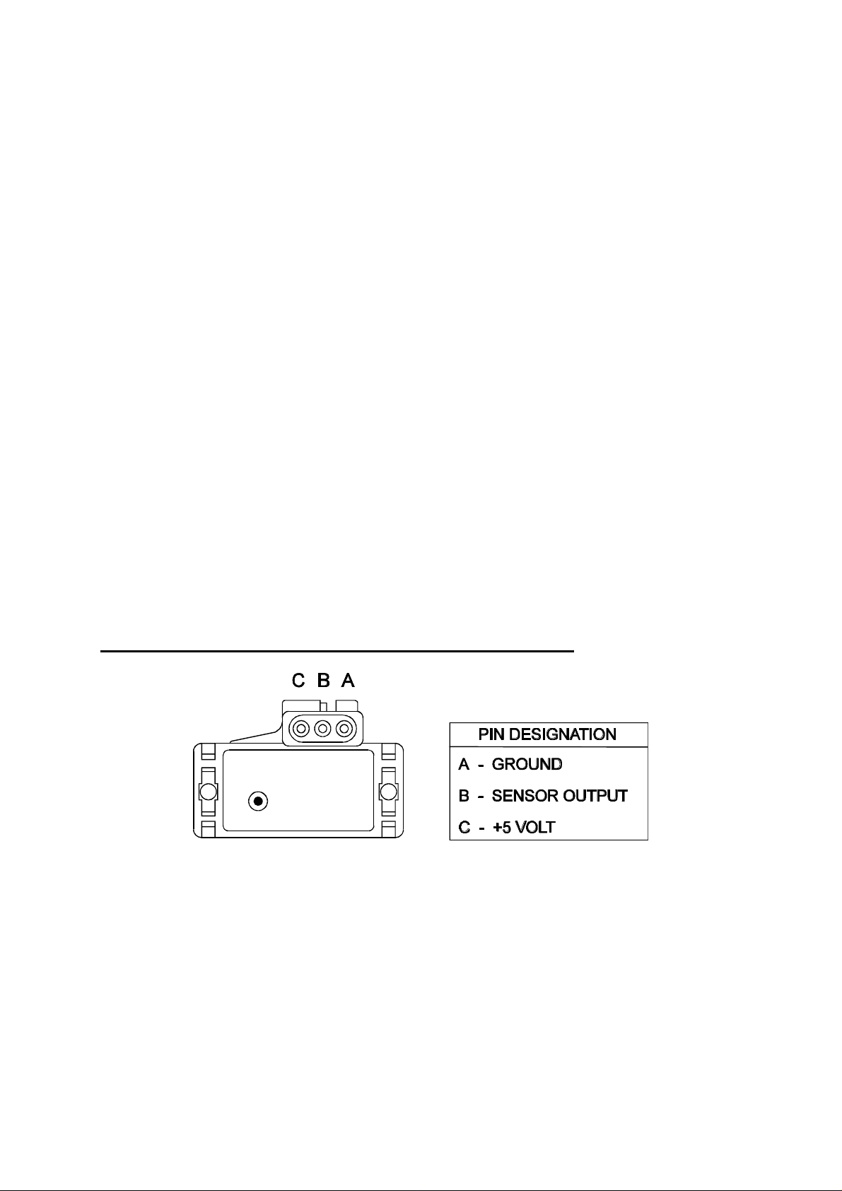
1.3.1. Manifold Absolute Pressure (MAP) Sensor
The MAP sensor is used to convert the manifold pressure into an electrical signal for the E6A
ECU to use. The sensor works in absolute pressures, thus its calibration is not affected by
changes in barometric pressure.
There are three types of MAP sensors that can be used with E6A system. Which sensor is
required depends on the engine setup.
1 Bar Sensor (Part No. 039 4070)
( -100kPa to 0 kPa) Normally Aspirated Engines
16
Page 17

2 Bar Sensor (Part No. 886 3189)
(-100kPa to 100kPa) Turbo or Supercharged
Engines up to 100kPa boost
(15 psi , 1 atmosphere)
3 Bar Sensor (Part No. 749 3169)
(-100kPa to 200kPa) Turbo or Supercharged
Engines up to 200kPa boost
(30 Psi, 2 atmospheres)
Note: Make sure you have the correct MAP sensor for your engine. The first three digits
of the part number is stamped on the sensor housing.
Engines running in Throttle Position Mode must use a 1 Bar sensor, not connected to
the manifold, so as to measure the barometric pressure.
Installations using a Barometric Pressure sensor will have two MAP sensors to connect.
One sensor will be for the Manifold pressure, the other will be for Barometric pressure.
The Barometric sensor must be a 1 Bar sensor. It connects to the Spare Input plug near
the Main Connector. This sensor can be mounted with the ECU and must be left open to
the atmosphere.
Mounting
The MAP sensor is usually mounted high on the engine bay firewall or inner guard using two
screws and with the hose nipple facing outwards. Connect the sensor to the inlet manifold via a
short length of vacuum hose and fasten with either hose clamps or nylon cable ties. Connect
the sensor to the main wiring harness using the appropriate plug. (For 1 Bar sensors the plug is
green, for 2 and 3 Bar sensors the plug is orange). Avoid mounting the sensor below the level
of the fuel injectors, because fuel may collect in the vacuum hose and run down into the
sensor. The sensor assembly is weather-proof but it is good practice to mount the sensor in a
protected position away from moisture and heat.
Note: Throttle position mode installations.
If you are using the throttle position to determine engine load, a 1 Bar MAP sensor must be
used, disconnected from the manifold and open to the surrounding air. The E6A will use the
sensor signal to compensate for barometric pressure.
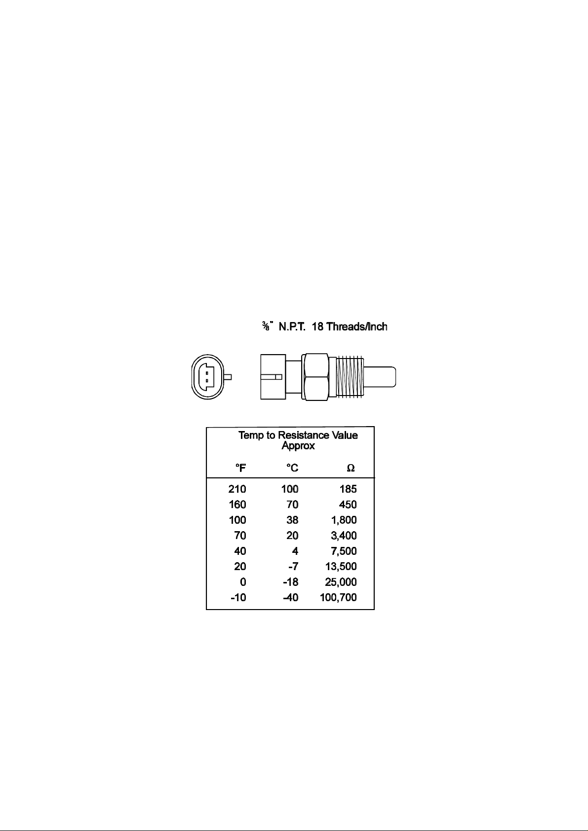
1.3.2. Coolant Temperature Sensor
The coolant temperature is used by the computer to determine warm up corrections and adjust
fuel mixtures.
The coolant temperature sensor has a solid brass temperature sensing tip. Refer to the diagram
for technical details of the sensor. The coolant sensor supplied is an industry standard
component and some engines may already have provision for this type of sensor.
17
Page 18
The coolant temperature sensor is designed to screw into a threaded hole and protrude into the
engine coolant stream. For air cooled engines, the sensor can be embedded directly into the
engine block or used to sense oil temperature.
Locate a suitable position on the engine which will allow the hole and thread to be machined,
and which gives access to the coolant stream. The sensor should be mounted after the engine
and before the thermostat in the coolant circuit. Since most engines have existing temperature
sensor holes, it is often possible to mount the Haltech sensor in one of these holes. A thread
adapter is sometimes necessary. In some engines only one temperature sensor hole exists and is
used for the dashboard gauge sender. It is usually possible to install a tee-piece to allow both
the dashboard sender and the Haltech sender to share access to the same threaded hole.
If it is necessary to drain the coolant from the vehicle to fit the temperature sensor then the
factory manual for the engine should be consulted for the correct procedure to restore the
coolant and purge the cooling system of air.
18
Page 19
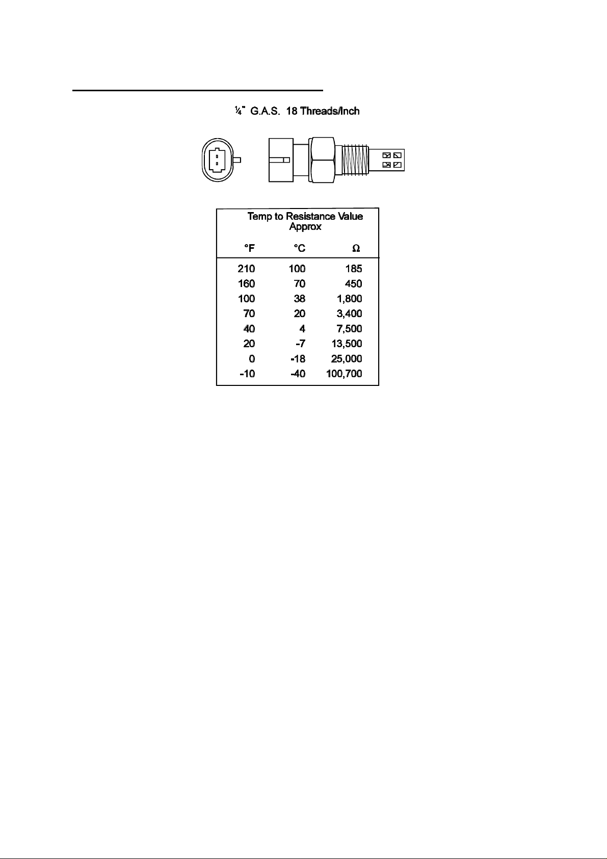
1.3.3. Inlet Air Temperature Sensor
The air temperature sensor is used to compensate for changes in air density due to air
temperature. Cold air is denser than warm air and therefore requires a greater volume of fuel to
maintain the same air/fuel ratio. This effect is most noticeable in forced induction engines. The
Haltech E6A will automatically compensate using the signal received from the air temperature
sensor.
The sensor should be mounted to provide the best representation of the actual temperature of
the air entering the combustion chamber, i.e. after any turbo or supercharger, and intercooler,
and as close to the head as possible. The sensor needs to be in the moving air stream to give
fast response times and reduce heat-soak effects.
Note: The Haltech air temperature sensor will read temperatures up to 120° C and
temperatures above this will be interpreted as a fault condition. The air temperature
after some turbos and superchargers can exceed this. If this occurs with your engine you
should consider fitting an intercooler to reduce air temperature and increase charge
density. If this is not possible then the air temperature sensor should be placed upstream
of the turbo or supercharger to monitor ambient air temperature.
Once a suitable position has been located for the air temperature sensor a hole should be drilled
and tapped to accept the sensor. Remove the manifold or inlet tract from the engine before
machining the sensor mount. Do not allow any metal particles to enter the inlet manifold of the
engine as these will be drawn into the engine and damage it. Wash all components before
reassembly.
19
Page 20
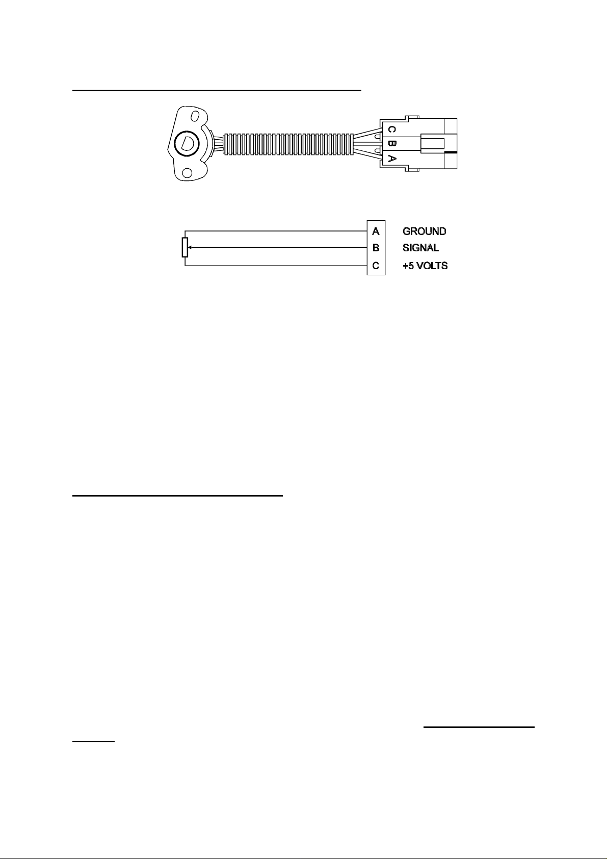
1.3.4. The Throttle Position Sensor (TPS)
The throttle position sensor is mounted to the throttle butterfly shaft to measure its rotation. A
TPS is common on many late model engines and the Haltech sensor should attach with little or
no modification. The throttle shaft must protrude from the side of the throttle body. This may
require the machining of the throttle body or the manufacture of a new throttle shaft. The inner
mechanism of the sensor rotates with the shaft. If the shaft is round then file a flat surface on
the shaft so that it will pass through the sensor assembly. The TPS should be mounted against
the side of the throttle body, using two screws, such that the throttle shaft and the sensor
mechanism can rotate freely. Make sure that the axis of rotation of the shaft is exactly
aligned with the axis of rotation of the sensor. Also, do not use the TPS as a throttle stop.
In either case, the TPS will be damaged. The absolute range of sensor movement is not
important as the sensor can be calibrated using the programming software.
1.3.5. Mount Ignition Module.
The Ignition Module has to be mounted on a flat surface (eg. the firewall) to ensure proper
heat dissipation and to avoid stress on the wiring connections. Also it is important to
preventing the module overheating by mounting it away from hot components such as exhaust
manifolds and turbochargers.
Included with the Haltech wiring harness is the Ignition Sub-loom. This connects the Ignition
module to the Main Harness. Locate this loom and connect it to the ignition module.
Connect the 3 flying leads. The black wire with the eye terminal is a ground connection. This
should NOT be grounded to the same point as the ECU to prevent ignition noise getting into
the power supply circuit of the ECU. The blue wire goes to the negative side of the coil. The
red wire should be supplied with Ignition On 12 volts. This can often be obtained from the
positive side of the coil.
NOTE: IF USING THE HALTECH IGNITION MODULE CONSTANT DUTY
CYCLE SHOULD BE SELECTED IN THE IGNITION SETUP PAGE.
20
Page 21
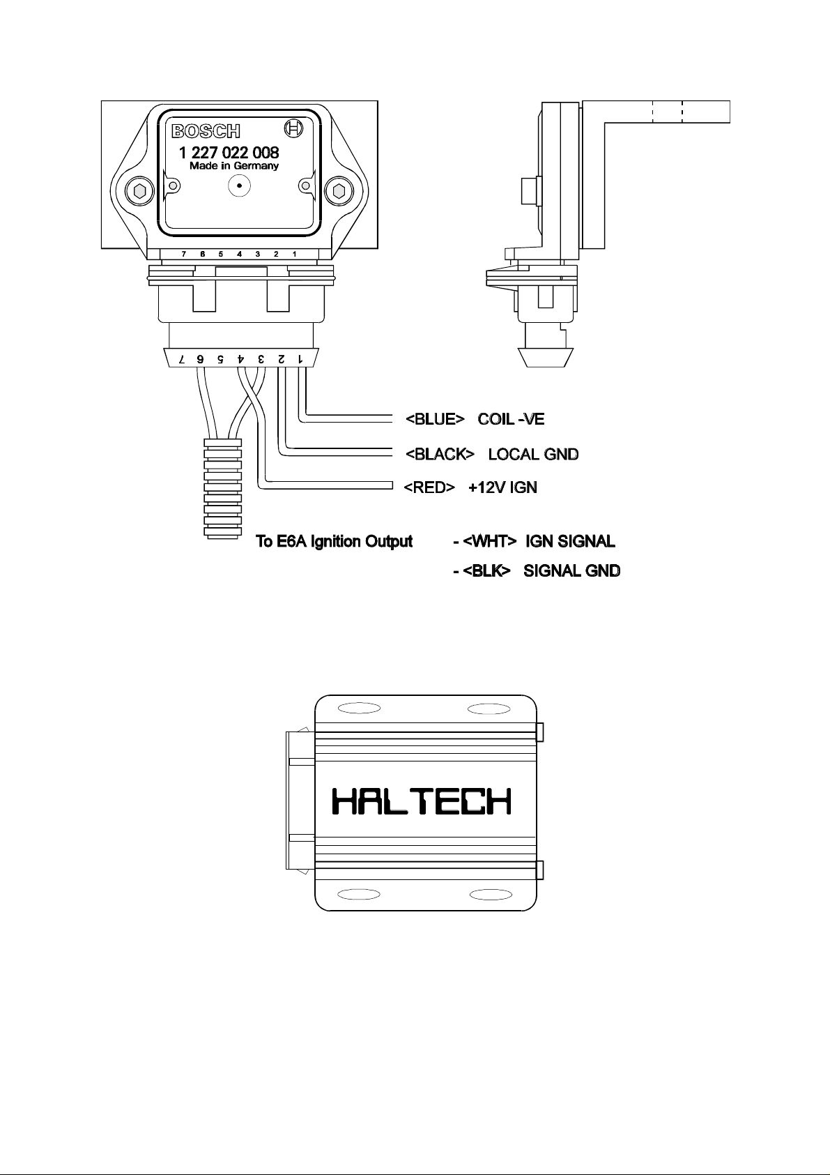
Bosch Ignition Module. The module must be mounted on the bracket, and the bracket must be
mounted to a suitable surface.
Haltech Ignition Module (part number HIM1) supplied with all E6A kits.
21
Page 22

1.3.6. Mount Optional Exhaust Gas Oxygen Sensor
The optional exhaust gas oxygen sensor must be mounted in the exhaust pipe near the exhaust
header or extractors, usually after the collector. The sensor uses the exhaust gas to detect if the
engine is lean or rich. Many late model engines already have provision for an exhaust gas
oxygen sensor and the sensor provided should fit any standard exhaust mount. Some exhaust
systems have the sensor mount up to around half a meter (2 feet) down stream from the
exhaust headers.
If the exhaust system does not have an existing sensor mount then a new mount will have to be
welded to the exhaust system.
When routing the electrical connections to the exhaust gas oxygen sensor do not allow the
harness to touch the exhaust pipe as the heat will damage them.
See Chapter 15 [15.3] for more information on exhaust gas oxygen sensors.
22
Page 23
1.3.7. Route Wiring Harness and Connect Sensors
Lay the main wiring harness out in the engine bay with the sensors mounted to ascertain the
best fit for the harness. Pass the wiring loom through a hole in the engine bay firewall and into
the passenger compartment where the ECU will be mounted. Either use an existing hole or cut
a new hole to suit. Use a rubber grommet or similar device to protect the harness from being
damaged by rubbing on the sharp edge of the hole.
IMPORTANT
•• Do not allow the harness to touch hot exhaust parts including manifolds or
turbochargers.
•• Try to route the main harness away from high voltage ignition leads. Under no
circumstances run any wiring parallel to, or in contact with the ignition leads.
Hint: Be neat. Run the harness in a tidy fashion. Try to run the harness along paths used by
original wiring. Use nylon cable ties to secure the harness in place, but do not stress the wiring
or connectors.
Once the harness is fitted, connect all the sensors to their appropriate plugs.
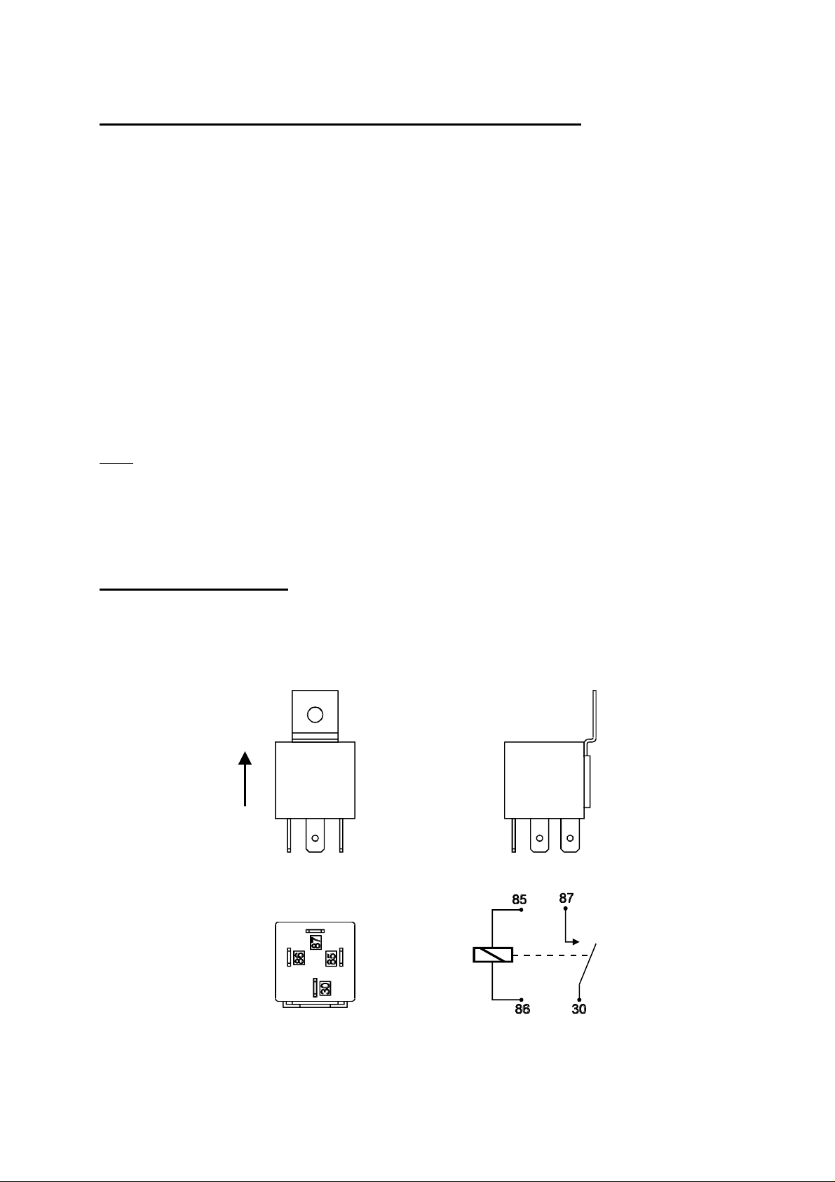
1.3.8. Power Relays
There are two relays used with the Haltech E6A, the Main Power Relay (with a grey wire) and
the Fuel Pump Relay (two orange wires). These relays are identical parts so it is not important
which relay goes in what connector.
23
Page 24
These relays should be mounted on the firewall or an inner guard. Do not mount the relays
such that they could catch and collect splashed water. Residual water inside the relay housing
will cause them to fail. Mount them with the tab upwards as shown in the diagram.
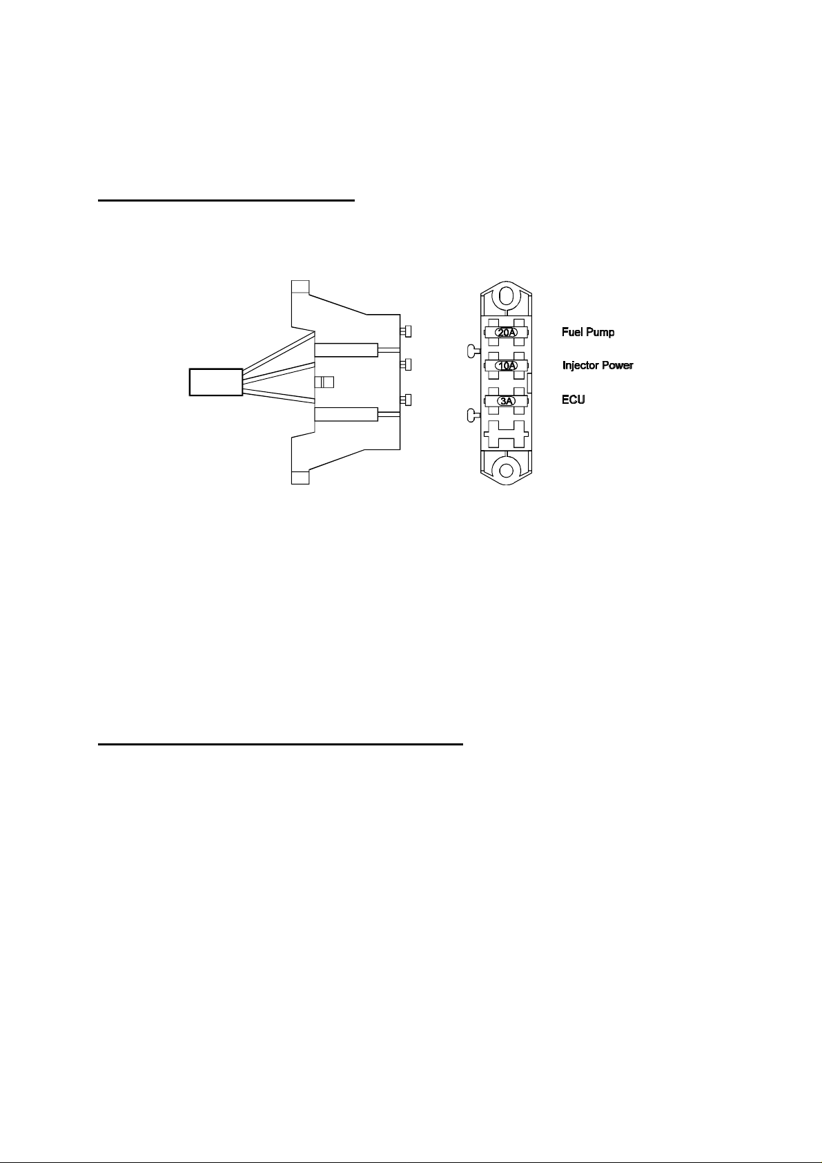
1.3.9. Fuse Block Assembly
The fuse block assembly holds the fuses that protect the various components of the Haltech
E6A system.
The fuse block is supplied from the factory with fuses installed. The fuse ratings are shown in
the diagram and should not be changed as these have been selected for best protection.
Altering the fuse ratings could cause severe damage to the E6A system.
The fuse block should be positioned so that it can be easily accessed in case of fuse failure. Do
not mount the fuse block where it could be exposed to water. Mount via the two screws holes
in the block. Ensure that vibration will not cause the screws to vibrate loose.
Connect the Fuse Block assembly to the Main Harness.
1.3.10. Electronic Control Unit (ECU)
The Haltech E6A is not designed to be waterproof. It is desirable that the ECU be given as
much protection from the environment as possible. It is recommended that the ECU be
mounted inside the passenger compartment, either on the firewall, under the dashboard or
under the passenger seat.
The ECU has four mounting holes that allow it to be mounted to most flat surfaces. In extreme
cases of vibration, the ECU should be mounted on rubber anti-vibration pads. When mounting
the ECU remember that the communications connector on the loom should remain accessible
for ease of programming.
24
Page 25
1.3.11. Flying Leads
Locate and connect the following flying leads.
Black - (Ground) Locate a good chassis ground point and connect the black wire. The best
spot is direct to the battery negative terminal.
Red - (Supply 12V) Locate a source of continuous 12 volts and connect the red wire.
Connecting direct to the positive battery terminal is suggested.
Grey - (Switched 12V) The grey wire is used to control the operation of the Haltech E6A
power relay. It needs to be connected so that it sees 12V only when the ignition is on
and during cranking. This wire does not draw a large amount of current (< 0.5A). Do
not connect to the accessory outputs of the ignition switch.
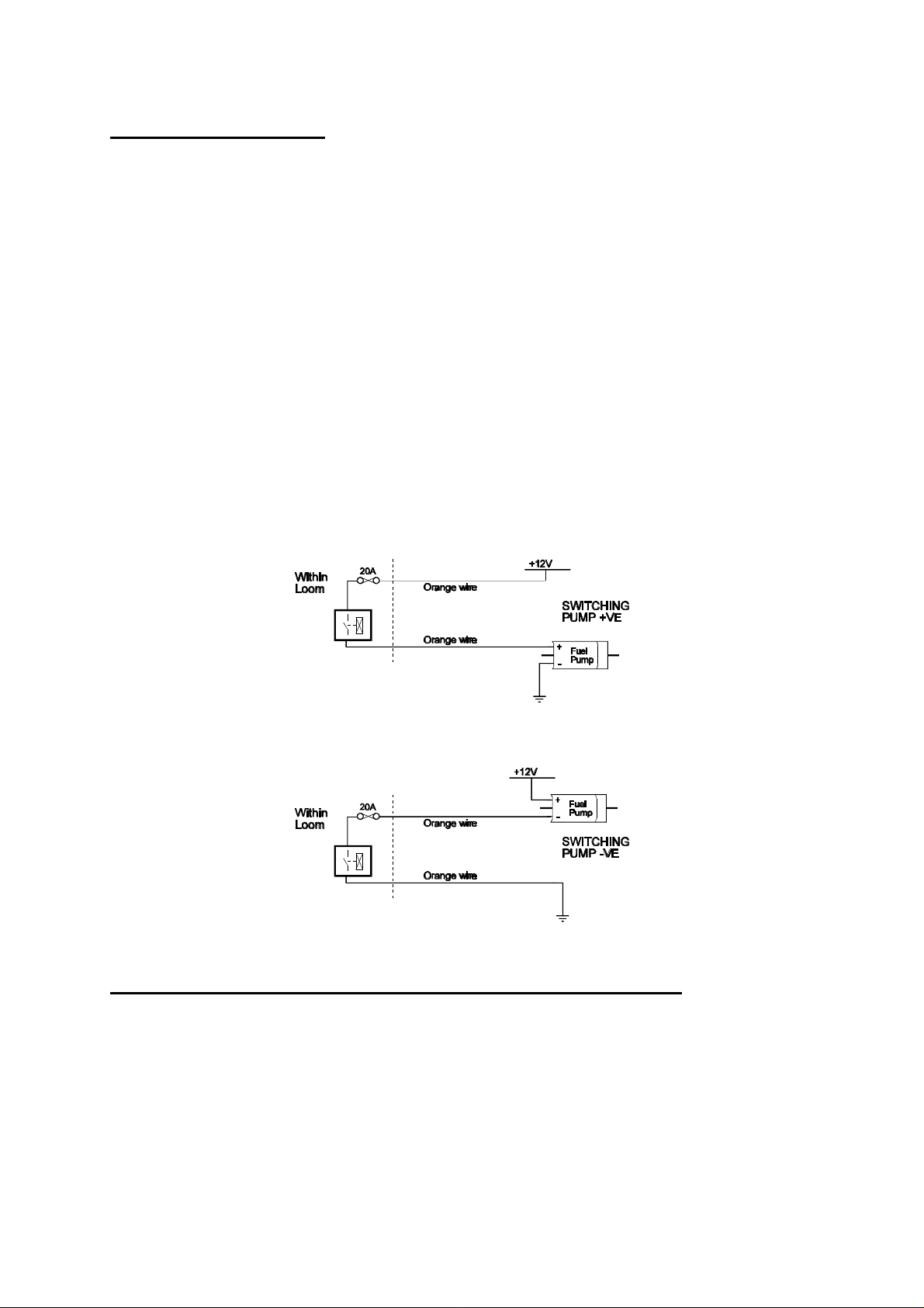
Orange - The two orange wires are used to operate the fuel pump. When the Haltech E6A
ECU wants to operate the fuel pump it will close the fuel pump relay connecting the
two orange wires together. The diagrams show two examples of wiring the fuel pump.
Do not add extra relays to the fuel pump circuit.
1.3.12. Install and connect Optional Idle Speed Motor
If you are not using the Idle Speed Control, tie the motor connector back neatly in the engine
bay. If the engine has a suitable Idle Speed Motor, connect it now. If you have to install the
motor, install and connect it now. For details on how to install and plumb the Idle Speed
Motor, see Chapter 14.
25
Page 26
1.3.13. Install and connect any Optional Outputs
If you are planning to use any of the Programmable Optional Outputs, install and connect them
now. Depending on what options you are using, the wiring will be different. For details on
wiring your particular options, refer to Chapter 16, Auxiliary Outputs.
1.3.14 Connect the Trigger Sensor
If the engine has a magnetic trigger input, you will need to connect the Reluctor Adapter now.
For details on how to connect the Reluctor Adapter to the main loom and to the trigger, refer
to Appendix G, Wiring Diagrams, and to Appendix E [E.2].
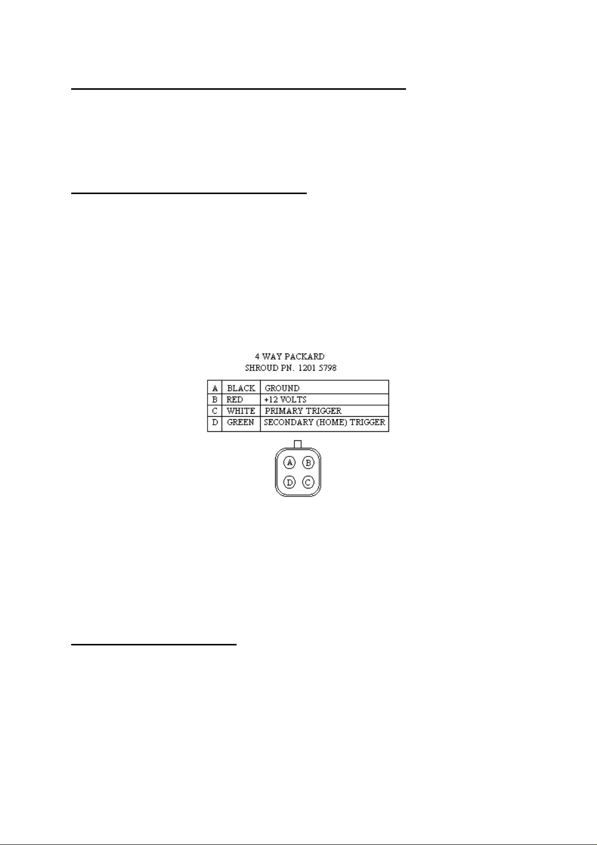
Hall Effect and Optical triggers need three connections - ground, power and the signal. The
trigger connector on the Main Harness has four pins. These pins and their connections are
shown in the diagram below. The Secondary (Home) Trigger is used for Direct Fire or
Sequential Applications. (See Appendix B). The secondary input can also be used as the Road
Speed input if it is not being used as a home trigger.
You will need to know what wiring your trigger requires. Some triggers need a series resistor
on the power line in order to limit current. Check your trigger system thoroughly. An
incorrectly wired trigger can cause damage, usually to the trigger.
The E6A requires one trigger per ignition event. For example, a V8 engine will require 4
triggers per engine revolution. It is recommended the you read Appendix E, Trigger Interface
for more detailed information on the trigger requirements of the E6A.
1.3.15 Connect the ECU
The ECU can now be connected and tested. Be sure to engage the clip on the main connector.
This will make sure the main connector parts mate correctly and reduces the mechanical strain
on the connector bodies. The system can now be tested as described in the following chapters.
26
Page 27

CHAPTER 2
Getting Online
Now that your Haltech E6A is installed with all the sensors in place the system can be
connected to the programming computer. This will allow the readings from all the sensors to
be displayed on the screen and checked for correct operation.
To connect the PC to the Haltech E6A ECU you will need the programming cable and
programming disk supplied.
2.1 Connecting the Haltech E6A to a Computer
The programming cable supplied with the Haltech E6A is a standard serial link extension cable.
One end of the cable will plug into the Main Harness PC Interface connector (near the main
connector). The other end should plug into the mating connector at the back of your computer.
The plug on the computer may be marked "Serial", "Mouse" or "COM". Almost all laptops
will have this plug. If there is no 9 pin plug which it will connect to, check to see if there is a
25 pin D-type plug available (some desk top computers will have this). If this is the case, an
appropriate cable can be supplied on request. Alternatively, most electronic retailers will have a
25-pin to 9-pin converter.
Any time you wish to communicate with the E6A ECU it needs to be supplied with power.
This usually involves just turning on the ignition switch. If at any stage power is not on, or the
programming cable is disconnected while attempting to communicate, the programming
software will display the message RECONNECT HALTECH. To rectify this, reconnect
power and/or the programming cable.
2.2 Operating the Software
2.2.1 Computer Requirements
The computer required to program the Haltech E6A can be any IBM-PC compatible personal
computer from the XT onwards (i.e. the AT, 386, 486 or Pentium computers). The
requirements are fairly modest. The computer must have at least 640K of RAM (with about
590kb free for executable programmes), one 3.5" disk drive and a CGA, EGA, or VGA screen.
(Virtually all reasonably modern laptops running MS-DOS (version 5.00 or higher) will fit this
description).
2.2.2 Installing the Software.
The Programming Disk supplied with the Haltech E6A has an installation programme that
allows you to install the software onto the PC’s Hard Disk. Most modern PCs have a hard
27
Page 28

disk. If your PC does not have a hard disk, the E6A Programme can ran directly from the disk
supplied. Installing the software on the Hard Disk will speed up the programme and avoid
having to fiddle around with floppy disks. The installation programme need only be run once.
If you do not have a Hard Disk, go to the section titled Running the Software from the
Floppy Drive.
To install the software follow these steps.
Boot up Computer
Turn your PCs power on and boot up MS-DOS as instructed by the computers Users Manual.
If a shell programme or menu utility runs automatically when you boot your computer, exit it
now. You should see something like this:
C:\>_
This is the ‘DOS Prompt’. It is DOS’ way of indicating that it is waiting for a command. The
C: indicates that the C drive is the drive currently selected. If you do not have a hard disk,
your prompt will probably look like this :
A:\>_
Select the Drive
To run the INSTALL programme, you must insert the supplied disk in the disk drive. If the
drive is the A drive, then it must be currently selected. To select the A drive (or B drive if it is
the required drive) type :
a:¬ or B:¬
The ¬¬ key is the Enter Key. On some keyboards it may be called the Return key. You should
now see the prompt :
A:\>_ or B:\>_
Run the INSTALL Programme
To run the Install program type :
install¬
The Install programme will now run. Follow the instructions given. The programme will
suggest that the software will be placed in the HALTECH directory. You can change the
destination directory, but it is not recommended that you do unless you understand how
directories work.
28
Page 29

When it is finished, the installation programme will tell you if the installation is successful. If it
was not, consult the trouble shooting section of this manual.
The E6A Programme is now ready to run.
2.2.3 Running the Software from the Hard Disk.
Boot your computer up as described earlier. If your computer is already on, make sure the C
drive is currently selected. To change to the HALTECH directory type :
cD \haltech¬
or, if you used a different destination directory, type that path.
To start the programme type :
e6a¬
The E6A programme will now run. The next section is on running the software from a floppy
drive. You can skip this section and go straight to the section entitled Azerty Keyboards.
2.2.4 Running the Software from the Floppy Disk.
To run the software from a floppy drive, boot your computer up as described earlier. Insert the
Programming disk in the disk drive. If the drive is the A drive, then it must be currently
selected. To select the A drive (or B drive if it is the required drive) type :
a:¬ or B:¬
You should now see the prompt :
A:\>_ or B:\>_
To start the E6A program type :
e6a¬
The E6A program will now run.
2.2.5 Azerty Keyboards
Most countries use a keyboard where the first six letter keys across the top row are :
qwerty
29
Page 30

This is called a Qwerty keyboard. Some countries use an alternative, which is called and
Azerty keyboard, where the Q and W keys are swapped with the A and Z keys respectively. If
you have an Azerty keyboard, you need to run the software slightly differently. When you
would normally type :
e6a¬
to run the programming software (not the installation software), you need to instead type :
e6a/a¬
The /A tells the programme you have an Azerty keyboard. The programme will adjust
accordingly.
2.2.6 Acknowledging the Risks
Once the program begins running a title page should appear briefly and then a warning screen
will be displayed. Read the warning and only proceed if you are prepared to accept the risks
involved in tuning your own engine. Faulty tuning can be dangerous and/or can damage your
engine.
2.3 The Online and Offline Modes
On the E6A system title page, the software asks whether to operate in ONLINE or OFFLINE
mode. The Offline mode is very useful to familiarise yourself with the Haltech software, but
should not be used to make lasting adjustments to the fuel maps unless there is a special reason
for doing so. If you wish to experiment and familiarise yourself with the software press N for
Offline mode, but if the ECU is installed and power is available then we suggest the Online
mode be selected. Press Y to select Online mode.
2.4 Using the System Online
In the Online mode there is a two-way flow of information between the ECU and the
programming computer. The communication cable must be installed and power must be
available to the ECU before the system can communicate. The Online mode will be used most
frequently. While using the system Online, you can view engine information directly and make
adjustments. Any changes or modifications made on the computer are instantaneous and will
be immediately recorded in the ECU. When the programming cable is removed and the ignition
switched off, the ECU will retain all of its memory. The maps do not need to be saved, but
keeping a copy on disk is always good practice and is recommended. (See 9.1)
30
Page 31

NOTE: If power is removed or the communication cable is disconnected or interfered with,
the following message will be displayed on the computer screen.
RECONNECT HALTECH
If this message appears check all connections and ensure that the communications cable is not
being interfered with. Also be sure that the Haltech E6A unit is receiving power. (i.e.. ignition
switch is turned "on".)
2.5 The Main Menu
When you select Online or Offline mode the Haltech MAIN MENU bar appears. This menu
bar allows access to submenus giving access to maps, file storage/retrieval, engine data and
options.
2.6 How to Quit
Throughout the program you can exit from any application by using the menu bars or hot keys.
Pressing §q§q in any page will prompt you to exit the program (i.e.. pressing qq while
holding down the §§ key).If you wish to exit YY press at the prompt.
2.7 Checking the Engine Data
The engine data option can only be used when the system is Online. This function allows all of
the engine data variables to be displayed on the screen
This is a very useful function for analysing the engine sensors. To bring up the engine data
press §e§e from any application. Otherwise it can be accessed through the menu bar by
pressing ¦O¦O and then EE for Engine Data.
Do not attempt start the engine if the Engine Identification has not been set up. Before
continuing check to see if all the sensors are operating correctly by viewing the engine data
page.
31
Page 32

CHAPTER 3
Engine Identification
3.1 Checking the Identification
The Identification page tells the E6A essential information about the engine characteristics.
Without this information being correct the engine cannot run properly. The Identification is
made up of several fields. Each field can have a number of settings, and you can change most
of the fields.
Use the Up and Down arrow keys (¢¢ and ££) to move between fields. The fields are either
Selection type, or Text type. The Selection type fields give you a number of valid entries for
that field. For example, the valid number of cylinders can be set to 1, 2, 3, 4, 5, 6, 8, 10 or 12.
The Tab and Enter keys (©© and ¬¬) keys are used to change this type of field. Each stroke
of the Tab key will display the next selection. The Shift and Tab keys together will step
backwards through the selections. Once the desired selection is displayed, the Enter key is
pressed to programme that selection. Text Fields require you to enter either text or numbers.
Once the field is selected, the new text can be typed in, with the Enter key to finish. An
example is the Rev Limit. This field can be set between 2000 and 16000 rpm. If you want the
rev limit to occur at 7000rpm, then you would need to select this field using ¢¢ or ££ and then
type 7000¬7000¬.
Here is a description of each of the Identification fields:
Cylinders: The number of engine cylinders needs to be entered here. This parameter is
used to determine the engine speed.
Load Sensing: The E6A can use either the manifold pressure or the throttle position as a
means of determining the engine load. Most engines operate using manifold pressure to
sense engine load. If your engine employs any form of supercharging, you must run in
manifold pressure mode. Only wild cams, motorbikes or heavily ported rotaries require
throttle mode - i.e.. engines whose vacuum signal is small, or fluctuates greatly. If you
are unsure what to use, contact your Haltech dealer.
RPM Limit: The E6A can limit the maximum rpm to which the engine will operate to.
Above this level the E6A completely cuts fuel or ignition (see below) to the engine.
When the engine speed drops below the RPM Limit the E6A will resume normal fuel or
ignition delivery. This is known as hard limiting. If the RPM Limit is not needed then
set this value above the highest operating point of the engine.
32
Page 33

RPM Limit Type: The RPM Limit can either be a fuel cut or an ignition cut. This field
determines what form of limit will be used. Be careful using an ignition cut on an
engine with a catalytic converter, as the unburnt fuel can damage it.
Units: The Haltech E6A programming software can display parameters in either Metric or US
units.
RPM Mode: The E6A fuel and ignition maps may be arranged either in 500 rpm increments
to 10,500 rpm, or in 1000 rpm increments to 16,000 rpm. Select the high - or low rpm mode here. Changing settings alters the way the ECU reads the Maps, and will
change the tuning of the engine dramatically. Do not change this setting once tuned
unless necessary.
Road Speed Value: This value calibrates the Road Speed reading. Some applications in
Advanced Mode can not use the Road Speed input trigger, and this field will not be
displayed.
Trim Control: The optional Trim unit can be used to control one of several parameters. This
field selects the controlled parameter. If there is nothing connected to the trim plug, the
trim will have no effect (except with boost control). The available functions are :
Fuel (Fine) ±12.5% adjustment of fuel.
Fuel (Coarse) ±50% adjustment of fuel.
Ignition +7 to -8 degrees adjustment of ignition advance.
Ign Trailing +7 to -8° adjustment for Rotaries only
Boost Control Boost trim for Wastegate control only.
Spare Input Function: The Spare input is an analogue input similar to the Trim Control
input that can be configured for one of several tasks. Its function is set by this field.
The available functions are :
General 0-5 volt input; no effect on ECU operation.
Fuel (Fine) ±12.5% adjustment of fuel.
Fuel (Coarse) ±50% adjustment of fuel.
Ignition Trim +7 to -8 degrees adjustment of ignition advance.
Ign Trailing Trim +7 to -8° adjustment for Rotaries only.
Baro Sensor Barometric Pressure Sensor.
Exhaust MAP Sensor Exhaust Pressure.(does not affect on ECU operation)
Care must be taken when setting this field. The circuit is biased to 2.5 volts. Therefore,
if there is nothing connected to the plug, the input will read 2.5 volts. If one of the
trims is selected, there will be no effect. But if the Barometric Sensor is selected, the
reading will be incorrect, and will have a large effect on the operation of the ECU.
2nd MAP Sensor: This field is only accessible when the Exhaust MAP Sensor is selected on
the Spare Input Function. It tells the software what sensor is being used (either 1 Bar, 2
Bar, or 3 Bar sensor) and how to calibrate the reading.
33
Page 34

Aux. In/Out Function: The Auxiliary Input/Output on the E6A can be configured for one of
several functions. Most of these functions relate to the configuration of the system. The
available functions are:
Disabled No effect on ECU operation.
Ignition Bypass Output - Bypass signal compatible with some
General Motors ignition systems. This function
allows the ignition system to provide the spark
at 10° BTDC at cranking speeds (below
500rpm). This aids starting.
Staging Signal Output - Logic output that indicates Staging
conditions. If Staging is selected, and the
Staged injector are firing, this signal will be
high (5 volts), otherwise it will be low (~ 0
volts).
Nos Input Input - This input is used in conjunction with the
Nos Optional Output. [16.13]
TCC Input Input - This input is used in conjunction with the
TCC Optional Output. [16.4]
Turbo Timer Input - This input is used in conjunction with the
Turbo Timer Optional Output. [16.12]
Anti-Lag Switch Input - This input is used in conjunction with the
Anti-Lag Optional Output. [16.14]
Since the Auxiliary Input/Output line can only perform one duty, all of the above
functions are mutually exclusive. i.e. although two programmable outputs exist on the
E6A, only one of the Nos, TCC and Turbo Timer may be chosen. None may be used if
the line is needed for Ignition Bypass. Keep this function in mind when deciding on the
E6A configuration you wish to run.
System Mode: This field sets the operating mode for the software. The software can be used
in either Basic or Advanced Mode. Most installations will only require the Basic Mode.
To determine if you need to use the Advance Mode, see the Introduction.
34
Page 35

Chapter 4
Adjusting Haltech Maps
The tutorials presented in this chapter are examples of how you might use the available
functions to make typical modifications to the maps. These tutorials are aimed at explaining
both why and how some typical changes might be made. They assume that you have the
software running Online on your PC, with the ECU powered and connected via the supplied
programming cable.
4.1 What are maps?
The injection times needed by the engine at different conditions is stored by the E6A in a
table of numbers called a look-up table. The E6A determines the engine's load and speed, and
uses these two parameters as an index to the table. This table is called the Fuel Map. For
instance, at an engine speed of 4000 rpm and at -20kPa, the relevant number in the table may
be 4.35. If the engine approximates -20kPa at 4000 rpm, then the computer will extract the
value of 4.35ms from the table as the base injection time. This value is then adjusted to
compensate for numerous conditions, such as temperature or acceleration, and then the ECU
holds the injectors open for that time on the next injection.
The Ignition Maps work in a similar way, except that it is the ignition advance that is stored
in the look-up table instead of the injection time.
It is possible to programme the E6A by directly changing the value of each number by
programming in the numerical mode, but this can be extremely difficult, so the Haltech allows
you to change the numbers by manipulating graphics in maps presented as bar graphs. (This is
much simpler and allows you to visualise the map)
Since it is difficult to interpret all the table's values at once, the programming software divides
the map by engine speed into a series of rpm ranges. Within the range, each load point is
represented by a vertical bar. Thus, when you view a range from the Fuel Map, you see a bar
chart of injection time versus load for all the load points in the table at that speed.
There are other tables in the E6A, such as those used for temperature corrections. They are
indexed by only one parameter, and so are not divided into ranges. These tables are also
called maps.
4.2 What is mapping the Engine?
Mapping the engine is filling the look-up tables with the correct values for your engine. This
is done by adjusting the heights of the bars within the maps. Bars may be adjusted one at a
time, or in groups. The Haltech programming software has been designed to make engine
mapping as simple and intuitive as possible.
35
Page 36

4.3 Using the Software
In order to make the software easy to use, the programme presents you with a menus bar at
the top of the display. The menu bar is accessed through simple combinations of key strokes.
Once the appropriate menu has been accessed a sub-menu appears giving choices on available
page heading. To increase efficiency there is also a number of hot-keys that allow you
movement between pages without accessing the menu bar.
4.4 Accessing the fuel maps
Pressing ¦m¦m will take you to the Maps Menu. From the Sub-menu choose the fuel maps
option. By using the cursor keys to move the highlight bar or pressing the underlined letter of
the option required in the case FF. This will produce a further sub-menu that will allow you
to choose a range to be viewed.
4.4.1 Fuel Setup
The Fuel Setup works in an identical way to the Identification. It’s fields are different and
relate to the way the fuel is delivered to the engine. Enter the Fuel Setup by pressing
¦s ¦s and then by pressing FF key. The fields in the Fuel Setup are:
Ign / By: Ignition Divide By is the number of ignition pulses that will be counted until the
next injection pulse. For almost all multipoint systems, injection should occur once per
revolution and so Ignition Divide By should be set to half the number of cylinders. If
the system is operating in Batch Fire or Sequential mode, or is a rotary, then a value of
1 is suggested.
Decel Cut-Off: A common fuel saving feature in original equipment computers is a fuel cut-
off on deceleration. This will cut fuel delivery to the engine while coasting down hills
with closed throttle. This feature can be enabled or disabled on the E6A. It is better,
when first tuning, to disable this function.
Injection Mode: The E6A splits its four injector driver outputs into two banks. INJ1 and
INJ2 comprise the first bank. INJ3 and INJ4 form Bank 2 (refer to the wiring diagram
at the back of this manual.) In Basic Mode, Fuel can be injected in three different
modes.
Multipoint injection fires all the injectors together. This is the most common setup and
will normally be used on engines with multipoint injection manifolds (one injector per
cylinder).
Batch-fire injection is usually used in throttle body or non-turbo rotary setups and fires
the two banks of injectors alternately. On eight and twelve injector fuel rails, with highflow injectors, this may also help reduce fuel pressure oscillations caused by all
injectors pulsing together.
36
Page 37

Staged injection is usually used on high boost turbo engines. Injector Bank 1 fires all
the time, just as in a multipoint setup. Beyond a set boost pressure, the second bank of
injectors is enabled. These "staged" injectors are normally upstream of the primary
injectors, adding to their fuel flow. The point at which the E6A switches in the
secondary injectors is set via the Staging Bar Number field. Staging permits high fuelflow capability, but maintains accuracy and controllability at light load and idle. See
Appendix D [D.3] for more details on staging.
In Advanced Mode, Sequential Injection can also be selected. This option is not a
straight forward setup. It requires more outputs for fuel then normally used. Before
selecting this option carefully read the section on sequential injection in Appendix B -
The Advanced Features.
Staging Bar Number: This field sets the point at which the staged injectors are enabled. See
Appendix D [D.3] for more details on staging. If the injection mode is not "Staged
Injection" then this field will not affect injection.
Zero Throttle Map: This feature allows the user to adjust a special fuel map that is used only
when the throttle is closed. This can allow a very quick and simple adjustment of the
idle fuel settings on engines with difficult idle characteristics. This option can be
disabled if not required.
Full Throttle Map: This feature allows the user to adjust a special fuel map that is used only
when the throttle is wide open on normally aspirated engines. With some manifold and
or throttle designs, pressures in the manifold can reach close to atmospheric pressure
before full throttle is applied. This effect can make tuning difficult around full throttle.
This map allows the full load settings to be easily set without interfering with lighter
load settings. The throttle position at which this Map is used is set by the Full Throttle
Threshold field.
Full Throttle Threshold: See the Full Throttle Map field above for information on this field.
This field can be set between 70 and 100.
Barometric Lock: If you wish to lock the barometric value that is stored by the ECU to a
set value and overide the start-up barometric correction, enable this option.
Barometric Pressure Lock at (mBars): Allows you to set the barometric value to
which the ECU corrections will be locked. Default is 1013mBars ( = 1 Atmosphere @ sea
level)
See Chapter 3, Engine Identification for information on how to adjust these parameters.
Once you have set up the fuel delivery via the Fuel Setup, you can view the Fuel Maps. Press
¦m¦m then FF to view the Fuel Sub-Menu. Then chose the range you wish to view by using
the function keys. While in the Fuel map, each range can be accessed by pressing the
NN,P P and JJ keys to move to the next, previous range and jump to a particular range.
37
Page 38
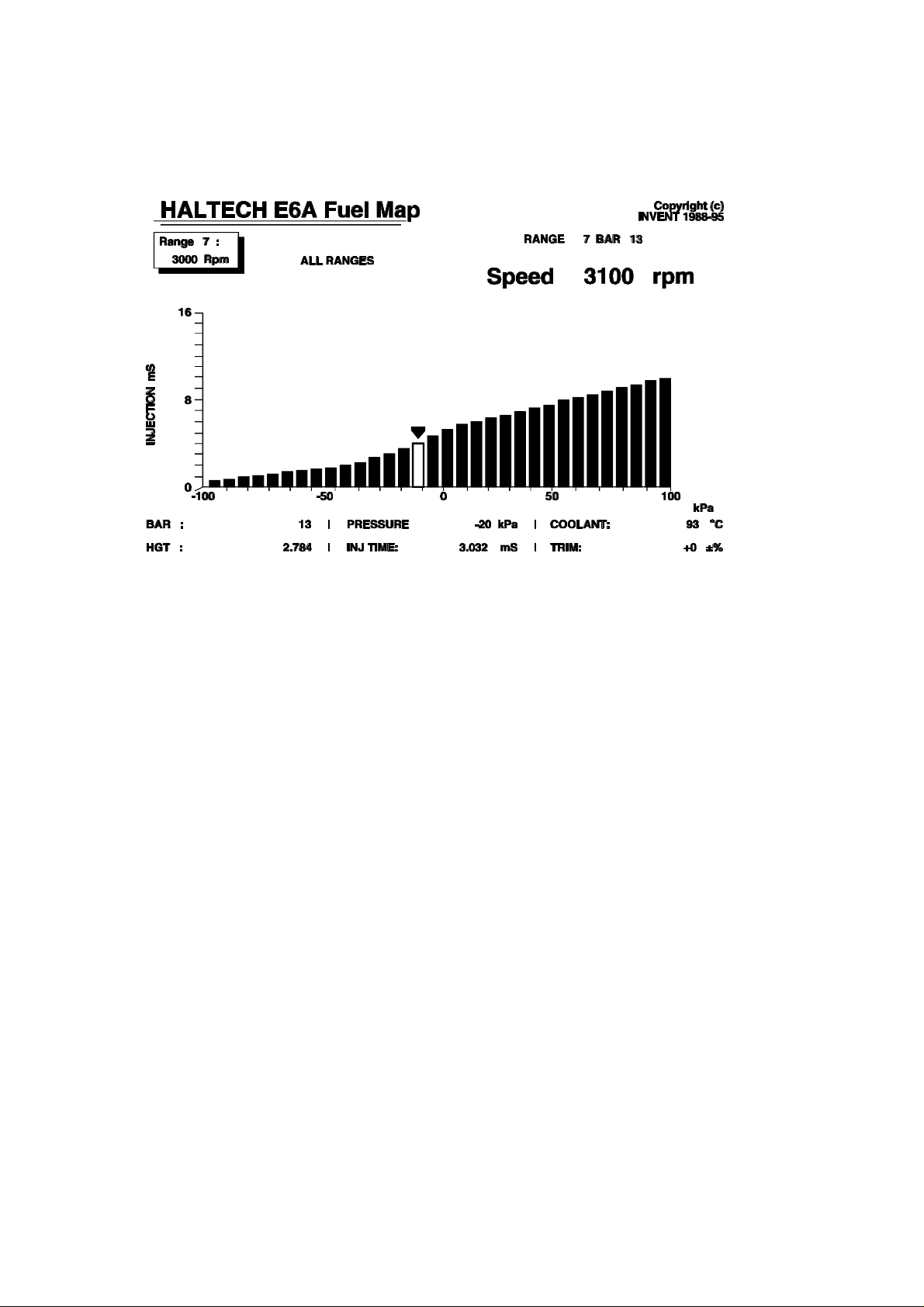
To view the map at the 3000 rpm range, press ““. When in the Fuel Maps sub-menu your
display should look like this:
Values from this bar chart would be used whenever the engine speed falls in the range
between 2750 and 3250 rpm (or, if in high-rpm mode, between 2500 and 3500 rpm).
In the top left is the range number and the speed range to which it corresponds. Opposite, in
large numerals, is the current engine rpm. The bar chart shows injection time, up to 16ms,
against the load parameter, either throttle position or manifold pressure. The axes are scaled
appropriately from the information in the Identification Page. Across the bottom of the screen
is written the number and height of the bar being adjusted, and other engine data. Above the
engine speed reading is the Range and Bar number that the ECU is currently using to
calculate injection time.
4.4.2 Adjusting Bar Height In The Map
The height of the Bars in the map can be readily adjusted by using the up and down arrows
keys, and the PgUp and PgDn keys (³³ ´´). See the command summary at the end of this
section for a full list of key functions. The bar that is highlighted on the computer screen
indicates the bar that you are currently adjusting. To change the highlighted bar, use the left
and right arrow keys (¥¥ ¤¤).
Try pressing the Up arrow (££) once. Notice that the outlined bar gets taller. Now try
pressing the Down arrow (¢¢) once. You are now changing the fuel delivery at 3000 rpm at
the load shown for the bar you have selected. Make sure you move the bar back to its
original height once you have tried adjusting it so as not to destroy the map you have loaded.
38
Page 39

Now try using the ³³ key. The outlined bar should jump up 0.096 mS. As the bar gets taller,
the fuel delivery is increased and the engine is enriched at that speed and load. Now press the
´´ key and the highlighted bar should move down 0.096 mS.
Note that the fuel delivery for the outlined bar is shown in the bottom corner of the display.
Note also that the injection time does not necessarily match the bar height as the injection
time is the actual injection time after various corrections have taken place. Also, the arrow
indicates the bar (i.e. number) currently being accessed by the engine. If the arrow was not
over the highlighted bar this would also cause the bar height and injection time to be different
as the bar height is the height of the bar being adjusted, not necessarily the value of the bar
currently being accessed by the engine. Try using the Control key and the Page Up key
together, §³§³,to move the bar up by 2mS. Move the Bar back down by using §´§´.
The changes you made took effect the instant you pressed the keys. You do not have to do
anything else to save these changes.
4.5 How To Quit
To return to the Fuel Map Menu from any of the map display pages press §f§f.Or through
the menus at the top of the display. Pressing §q §q keys simultaneously at any page or map
will allow you to exit the Haltech program and will return you to MS-DOS. You should
always exit the program before switching off your computer.
4.6 Accessing the Ignition Maps
Pressing ¦m¦m from any page will take you to the Maps Menu. From here you choose II
for the Ignition maps. Or you can access the ignition maps directly through §I§I from any
other application.
4.6.1 Ignition Setup
The Ignition Setup works in an identical way to the Identification. Its fields are different and
relate to the way the ignition advance is determined for the engine. Enter the Ignition Setup
by pressing ¦s¦s then II. The fields in the Ignition Setup for Basic Mode are:
Trigger Degrees : This field tells the ECU where to expect the Main Trigger to occur. This
field is very important for the correct operation of the ignition. If it is incorrect, the
spark advance will also be incorrect, which could lead to engine damage. The ECU
needs to receive an input trigger at a fixed engine angle Before Top Dead Center
(BTDC) for each spark. This trigger may be set between 60° and 100° BTDC. See
Chapter 5 [5.2-3] for detail on how to check the timing and this field.
Lock Timing at 10 Degrees: This field is used for testing the trigger input. It allows the
timing to be locked at ten degrees regardless of the engine speed and ignores the
ignition map settings. This feature is further discussed in Appendix E
39
Page 40

Trigger Edge : This field determines whether the E6A is to trigger on a rising or a falling
edge. Refer to Appendix E - Trigger Interface for details on how to determine this
setting. If a Reluctor Adapter is being used, this field should be set to Falling.
Output Type: This field is used to determine how the ignition output signal is to be defined.
Constant Duty should only be used with the Haltech Ignition Module or other
“intelligent” igniters and special aftermarket systems that perform dwell control.
Constant Charge may be selected if the igniter operates simply as a switch (ie a “dumb”
igniter) and requires a dwell signal.
Coil Charge Time: Only required if Constant Charge selected as Output Type. This is the
time require to charge the coil fully, or until the igniter’s current limit is reached,
typically 4-5 ms. Refer to Appendix E for additional information.
Coil Break Time: Only required if Constant Charge selected as Output Type. This is the
minimum time the E6A should allow before the coil is switched on again, usually 1-2
ms. Coil Break Time defines the ignition output signal when there is insufficient time to
charge the coil fully. refer to Appendix E for additional information.
Output Edge: The Output Edge should be falling with a 30% switch when using a Haltech
igniter as supplied with the E6A kit (This is the default setting). If you are using any
other igniter, refer to Appendix E [E.4] for details on how to set this field for the
igniter used.
In Advanced Mode, several other fields are available. Some of them are fairly complex and
should not be changed unless you are totally familiar with their operation. Consult Appendix
B - The Advanced Features, to familiarise yourself with their functions. The Advanced Mode
fields are :
Trigger Type : There are three settings for this field :
The Standard trigger sends one trigger to the ECU for each spark event. On a V8, for
instance, there are 4 firing strokes for each revolution and, therefore, the E6A would be
expecting 4 triggers each revolution. These triggers should occur between 60 - 100°
BTDC (as described under Trigger Degrees above) and can be generated by either a
crank angle sensor or cam angle sensor in a distributor.
A Multitooth trigger has multiple triggers for each ignition event. The number of teeth
must be a multiple of the number of cylinders. For instance, on a V8 for each engine
cycle (2 revolutions) you would expect there to be 8, 16, 24, 32 etc. The ECU needs to
know if this is the type of trigger being used or else too many sparks and fuel pulses
will be delivered. A multitooth trigger also requires a Synchronisation Event (usually a
Home Trigger) to give the ECU a reference to its position. For more information on
Synchronisation Events consult Appendix E [E.3]. For multitooth triggers, consult
Appendix B - The Advanced Features.
A variation on the multitooth trigger is the Motronic trigger. This setting is designed to
be compatible with the trigger wheel used for Bosch Motronic controlled engines.
40
Page 41

These wheels have 58 teeth with a two tooth gap (i.e. 60 teeth positions, with 2
missing). The missing teeth perform the task of the synchronisation event, eliminating
the need for a Home Trigger. Consult Appendix B - The Advanced Features [B.4]
for more information.
Number of Teeth : This field is only available for the Multitooth and Motronic trigger
settings. It is the number of ‘effective’ teeth per cam revolution (2 crank revolutions).
‘Effective’ teeth means to include missing teeth. In the case of the Motronic trigger, the
2 missing teeth are counted, giving 120 teeth per cam revolution.
Tooth Offset : This is the number of teeth from the synchronisation event to the trigger angle.
(For a more involved definition, consult Appendix B - The Advanced Features
[B.4]).
Home Edge : Similar to the Trigger Edge field, this field determines the edge for the Home
signal. If a Reluctor Adapter is being used, this field should be set to Falling.
Spark Mode : The E6A can have multiple ignition outputs. This field indicates if more than
one ignition output is required. See Appendix B - The Advanced Features [B.4] for
more information. The available settings are :
Distributor - This is for a single distributor, single coil ignition system. A slight
variation is the twin spark per cylinder engines, which use two coils and either one or
two distributors, but fire the sparks together.
Twin Distributor - Some V8 and V12 engines use two distributors, one on each bank.
Each distributor has its own coil, and they fire alternately.
Direct Fire -Direct Fire systems do not use a spark distributor. Each spark plug is fired
from its own coil, or (more often than not) companion cylinders are fired together
using twin tower coils Consult Appendix B - The Advanced Features for details on
the requirements for Direct Fire.
Coils on 4Cyl Motor : It is possible to Direct Fire a 4 cylinder engine with either two coils
firing waste spark or 4 coils without waste spark.. This field tells the ECU to use either
2 ignition outputs or 4. (Consult Appendix B - The Advanced Features for details)
Engine Type : Two engine types are selectable through this field - Piston and Rotary. This
field should be set according the to engine type you are using. Rotary must be selected
for the E6A to generate trailing spark ignition signals.
The Ignition Map is adjusted in a similar way to the Fuel Map. The keystrokes are the same,
except that one increment is one whole degree advance or retard. The best way to initially set
up the Ignition Map is to use the Library Maps, and then return to the Ignition Map later if the
ignition curve needs modification. Ignition Library Maps are explained in Chapter 5 [5.4],
Starting the Engine.
An example of an ignition range for a turbocharged engine could look like this :
41
Page 42

42
Page 43

4.7 Time Saving Functions
The following list of commands can be used whenever the graphs for most of the maps are
being displayed by the Haltech programming software.
Note: When two keys are displayed together, such as ¦r¦r, this means that the second key
must be pressed while the first key is held down. In this case, the ¦¦ key would be held down
while the rr key is pressed.
4.7.1 Current Location - ²²
Pressing ²² will take you to the range at which the engine is running, and highlight the bar that
is currently being used. This bar is easily identified by an arrow directly above it pointing
down. As the engine speed and load changes, the arrow moves with it. The Home key is useful
for finding the engine's operation point very quickly.
4.7.2 All Ranges - ¦r¦r
Across the ranges, the curve of the fuel map does not change greatly. Usually the shape
remains much the same, and the height changes according to the volumetric efficiency of the
engine. In order for all the fuel ranges to initially be set up quickly, the Haltech E6A system
allows you to programme all rpm ranges simultaneously with the same data. ¦r¦r turns All
Ranges on, and the words All Ranges appears under the title.
When the All Ranges function is active, a bar adjusted on one graph is copied to the same bar
on all the ranges. If you use this option, you can set the shape of the map at any range, and all
other ranges will be identical at every bar you adjusted. This feature enables all graphs to be
given an initial shape that should run the engine, albeit rather roughly. Once you have used the
All Ranges option for a starting point, press ¦r¦r once more to exit the All Ranges option
and tailor each map individually.
This option is only available on the Base Fuel and Ignition Maps.
4.7.3 Selecting Groups of Bars
Groups of adjacent bars may be highlighted and adjusted together.
Hold §§ while using the left or right arrow keys, ¥¥ ¤¤, and you will highlight a group of
bars. This group will now act in unison when increasing or decreasing the height of the Bars.
To de-select the highlighted Bars use the ¦¦ and arrow keys together.
43
Page 44

4.7.4 Percentage Changes -¦p¦p
Using this function will prompt you to enter a percentage change to the selected bars. An entry
of "20" will increase each bar by 20%, while an entry of "-15" will decrease the bars by 15%.
This change only affects the highlighted bar(s).
4.7.5 Linearise - ¦l¦l
When a group of bars is selected (more than two), this function can be used to set the values
between the end points. Highlight the bars between two load points that are known to be
correct and press ¦l¦l. The programming software will automatically adjust all the bars
between the two end points to form a straight line. This feature facilitates fast programming
and the smoothing of maps.
4.7.6 Numeric Mode - ¦n¦n
This will take you into numerical mode, displaying the map as a spreadsheet. This mode is
available if wanted, but graphical mapping is recommended as it is much easier to use. To exit
from Numeric Mode and go back to using the maps press the °° key.
4.7.7 Bar Increments - ¦i¦i
The Up and Down arrows, ££ ¢¢, normally change the bar height in the maps by a pre-
determined amount, usually the smallest possible increment. PgUp and PgDn change the bars
also by a pre-determined amount. These increments (the value of the keystroke) can be
changed by the user. ¦i¦i will bring you to a screen where the increments themselves can
be changed.
Normally, the bars are altered by adding or subtracting a fixed amount. The adjustment keys
may instead apply a percentage change on each keystroke. ¦p¦p on the Bar Increment
Screen will switch to percentage increments, §f§f will return you to fixed increments.
¦l¦l will space out increments evenly between the Up/Down Arrows field and the Ctrl
PgUp/PgDn field.
4.7.8 Help Function - ¦h¦h
A simple help screen can be pulled up at any time by pressing ¦h¦h. All key commands are
summarised and listed here.
44
Page 45

4.8 Duty Cycles
Fuel delivery is obtained by pulsing the injectors synchronised with the engine speed, allowing
fuel to flow during the period that the injector is open. The time whilst open is called the
injector pulsewidth. As rpm increases it is possible for pulsewidths to overlap so that the
injectors are effectively switched completely on. This is referred to as 100% duty cycle.
When 100% duty cycle is reached the fuel flow from the injectors has reached its maximum.
Increasing revs brings with it the danger of an engine lean out. LEANING OUT AN ENGINE
WILL CAUSE DAMAGE TO THE ENGINE IN MOST CASES.
The tables and graph below show the point at which the injectors will reach 100% duty cycle.
Care should be taken that the engine cannot rev above the point when 100% duty cycle
is reached as there is a danger that damage will be caused to the engine. It is not common
for this to happen but the potential for damage under these circumstances is strong so care
should be taken to check this factor.
Maximum Injection Time (in milliseconds[ms]) =
(120,000 x IgnDivideBy)
(Rpm x No. Cylinders)
eg. Maximum injection time for a four cylinder, on ign/by 2 red-lining at 6000 RPM is
(120,000 x 2)/(6000 x 4) = 10,
so the absolute maximum injection time at 6000 RPM on this engine is 10 ms. If the injection
time needs to be greater than this, then your fuel system cannot meet the demands of the
engine. You will need to increase the fuel supply, by increasing injector size, fuel pressure, or
adding extra injectors. Refer to Appendix D for details on how to increase fuel supply. As a
general rule of thumb, injectors should not run beyond 85% duty cycle.
45
Page 46

Injector Duty Cycle appears on the Engine Data Page and on Datalogs for you to monitor the
approach to maximum fuel flow.
46
Page 47

4.9 Command Summary for Maps
¥¥ , ¤¤ - move left/right highlighted bar(s)
££ , ¢¢ - increase/decrease highlighted bar(s)
³³ , ´´ - increase/decrease highlighted bar(s)
¨³¨³ ,
¨´¨´ - increase/decrease highlighted bar(s)
§³§³ ,
§´§´ - increase/decrease highlighted bar(s)
§¤§¤ ,
§¥§¥ - select (highlight) next bar
¦¤¦¤ ,
¦¥¦¥ - de-select end bar
¦P¦P - enter Percentage change to highlighted bars
¦L¦L - Linearise between end points of highlighted bars
¦H¦H - bring up Help screen
¦I¦I - set Increments
¦N¦N - enter Numeric mode
¦R¦R - toggle All Ranges mode
NN - move to Next range
PP - move to Previous range
JJ - jump to range of value entered
²² - go to current engine range/bar
©© - switches option in setup pages
47
Page 48

Chapter 5
Starting the Engine
There are a few things that need to be done before the engine should be started. Make sure
that the ECU is powered (ignition on) and the Haltech Software is Online. Go to the Engine
Data Page to check that the ECU is communicating properly, and that the sensors are reading
correctly. Check again that the Identification, the Fuel Setup and the Ignition Setup are all set
correctly. In particular, check the No. Cylinders, Ign Div/By, Load Sensor and Injection Mode
parameters. If any of these are incorrect, the engine may run, but proper tuning will be
impossible.
5.1 Calibrating the Throttle Position Sensor
The throttle sensor must be calibrated so that the ECU knows the start and stop positions of
the sensor. Set the idle throttle opening using the idle adjust screw. If the required opening for
idle is not known, make an estimate but keep in mind that this may be the reason for poor idle
later on, and further adjustment may be needed. Choose the "calibrate throttle" option from the
options menu and follow the instructions on the screen.
5.2 Checking the trigger
It is a good idea to check that the E6A is receiving a reliable trigger signal. Remove the 20A
fuse from the fuse block. This will prevent the fuel pump from running and the engine from
starting. The engine should then be cranked over on the starter and the rpm displayed on the
engine data page should read about 100 to 300 rpm. If the engine speed is zero or is erratic
then refer to the section in Chapter 1 [1.3.14] regarding trigger setup. If the trigger is
operating correctly then replace the 20A fuel pump fuse.
5.3 Checking the Base Timing
The E6A uses a timing reference taken from either the cam angle sensor or flywheel sensor.
This give the E6A the reference on which to position all ignition timing. If the timing is wrong
then the E6A cannot function correctly. To ensure that this base timing is set correctly the E6A
has a TIMING CHECK FLAG
When the Timing Check Flag is set, the ignition timing is forced to 10° Before Top Dead
Center (BTDC). This is regardless of whatever ignition timing Maps are currently in the E6A.
To enable this flag, press ¦s¦s from the Sub-Menu select the Ignition Setup. Using the arrow
keys move to the Timing Lock option. If it reads Timing Check On, the flag is enabled. If it
reads Timing Check Off, then the flag is disabled. The flag is toggled by pressing ©©. If the
Timing Check is on, the ECU will lock the timing to where it believes 10° advance to be.
To check the base timing you should now start the engine with the Timing Check on. The
engine should now start and run although with only 10° of ignition advance the idle speed may
be lower than usual.
48
Page 49

If the engine does not start it may be because the fuel requirements are not right. If this is the
case, it is suggested that you remove the 20Amp fuse for the fuel pump and do the timing
check while cranking. This will require two people : one to crank the engine and one to
operate the timing light. It can be difficult to check the timing accurately at cranking speeds.
Removing the spark plugs will help the engine to rotate at an even speed. Once you have
checked the timing at crank, leave the Timing Check on, skip the next section on loading an
Ignition Library Map and go to the section on Determining Engine Fuel Needs. Once you have
the engine starting and idling, return to this section, check the timing again, and then load the
Library Map.
Use an ignition timing light to check that the ignition timing is set to 10° BTDC. See the
workshop manual for your engine for details on checking ignition timing and the use of a
timing light.
The timing should be locked at 10° BTDC. If it is not then the angle at which the ECU is being
triggered is not the same as the angle in the Trigger Degrees field in the Ignition Setup. If the
timing is miles out, go back and check all the angles again. If you have guessed the trigger
angle, try and calculate it properly. Remember that the angle is in crank degrees, not distributor
degrees. Also make sure the trigger edges are correct. These can have a very large affect on
the trigger angle.
If the angle is a little out, it is just a matter of aligning up the actual trigger angle with the angle
in the Trigger Degrees field. There are a few ways to do this :
If the timing reference is taken from a distributor, then you may be able to rotate it while
using the timing light until the engine is at 10° BTDC. Be wary about adjusting the base
timing in this manner by any more than a few degrees as it can upset the rotor phasing.
For details on rotor phasing, see Appendix F.
If the reference is taken from a cam angle sensor (such as in a distributorless direct fire
engine), then if it is possible, rotate the sensor while using the timing light until the
engine is at 10° BTDC. With a cam angle sensor, there is no need to worry about rotor
phasing.
The last method is to change the Trigger Degrees field in the Ignition Setup. (See the
previous Chapter for details on how to change this field). If you are using a crank angle
sensor then this is the easiest way to adjust the base timing. The Trigger Degrees field
tells the ECU where the trigger is occurring. Once the ECU receives this trigger, it
calculates how many engine degrees to delay until it has to fire the spark. For example, if
the trigger is at 70° BTDC, and the Timing Check is on, the ECU will delay 60° and then
fire the spark at 10° BTDC. If however, the trigger was actually at 80° BTDC, but the
Trigger Degrees had a value of 70, the ECU would still delay the 60° and the engine
would fire at 20° BTDC. Changing the value of the Trigger Degrees field to 80 would
increase the delay from 60° to 70°, and the engine would now fire at 10° BTDC. When
adjusting the parameter, do so in small steps, say 5 or 10 degrees at a time. This will
allow you to check that you are moving in the right direction.
49
Page 50

You must now ensure that the timing does not move as the engine speed changes. Give the
engine a few quick revs while using the timing light to check that the ignition timing stays at
10° BTDC. If the base timing is locked at 10° BTDC and does not change with engine speed
then you are ready to load an Ignition Timing Map and clear the Timing Check Flag.
If the ignition does change with engine speed then see the Troubleshooting procedure in
Appendix A
50
Page 51
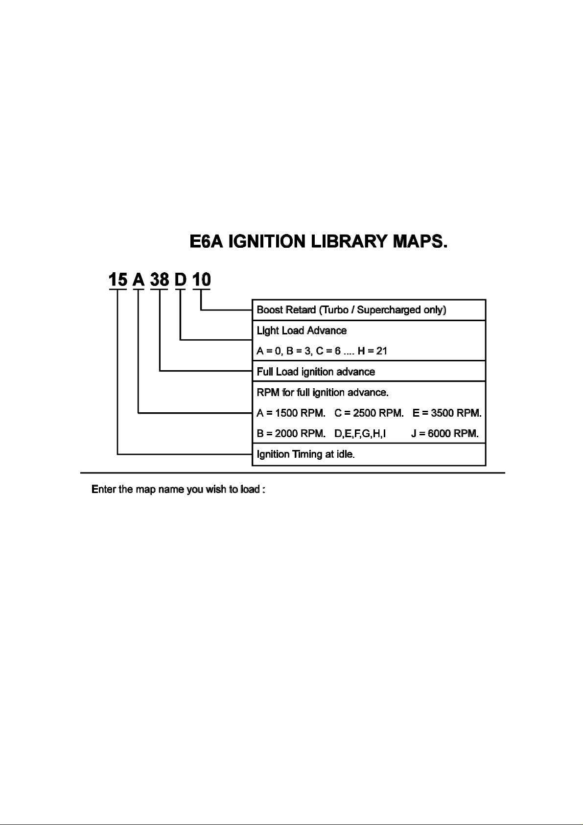
5.4 Loading an Ignition Library Map
The E6A has an effective and time saving method of programming the ignition curve using
Library Maps. Each ignition timing Map in the library is slightly different. By becoming familiar
with the library you should be able to select an ignition timing Map that will suit your engine.
Each ignition timing Map in the library is accessed by a different name. The name reflects the
characteristics of the Map. Names can be up to eight alphabetic or numeric characters in
length. The ignition timing library Maps use these eight characters as shown, where the first
character is always a number.
• The first two characters in the ignition timing Map name specify the ignition timing to be
used at idle. The example Map name shown has 15 degrees of advance at idle.
• The third character in the ignition timing Map name specifies the Rpm at which
maximum advance occurs (i.e.. how quickly advance changes with engine speed). This
character is a letter of the alphabet. Option A has full advance in by 1500 Rpm. Option B
has full advance in by 2000 Rpm. Option C at 2500, etc. up to J for 6000 Rpm.
• The fourth and fifth characters in the ignition timing Map name specifies the maximum
advance at atmospheric pressure. Cruise or light load advance is added to this value,
while retard on boost for turbocharged or supercharged engines is subtracted from it.
51
Page 52

• The sixth character in the ignition timing Map name specifies the extra ignition advance
to use at light loads such as highway cruise. This is equivalent to the vacuum advance on
a distributor. If this character is A, there is no extra advance under light load. Each
successive letter of the alphabet after A adds 3 degrees of ignition advance to the full
load advance under light load, up to the letter H. (H = 21°)
• If the engine is turbocharged or supercharged then the seventh and eighth characters
specify the ignition retard the engine is to get under boost. This value is subtracted from
the atmospheric pressure advance value. If the engine is not turbocharged or
supercharged, then leave the name only six characters in length.
A description of each parameter is displayed on the Library Maps page to save you referring to
this manual.
As mentioned above, it is suggested that the timing be checked before starting the engine. If
the ECU successfully locks the timing at 10° then you should load a library map that will get
the engine started. Try be conservative : you should not be looking to gain the last few percent
in performance immediately. If you know the factory settings for idle, vacuum and full load
advance for your engine you can use those values to load an extremely effective Library Map.
5.5 Determining Engine Fuel Needs
You should now be ready to start the engine. At this stage, you should not be using the Zero
Throttle Map. Check that it is disabled in the Fuel Setup. Go to the Fuel maps and display the
0 rpm range. During cranking, the pointer will appear across this page, until the engine speed
picks up and lifts into the 500 and 1000 rpm ranges. Press the ²² key to jump to the current
load point immediately.
If you are using manifold pressure as the load sensor, the engine will be close to atmospheric
pressure during cranking. If you are using throttle position, then the E6A will be using bar 1
while cranking and idling. Once the engine is tuned, you should not need to apply any throttle
to get the engine to fire. When cranking the engine watch for the indicator arrow over the bars.
This will tell you what bar the E6A is using to calculate the fuel. The bars that the arrow
indicates are the Bars that will need to be adjusted to get the engine to run.
If the engine is not firing at all, check that spark is available. Also check that the spark plugs
are clean and are not wet. It is unwise to crank on the starter motor for extended periods. The
engine should fire and run within the first few seconds of cranking.
If the engine misfires and blows black smoke then the mixture is rich and the bars need to be
lowered. If the engine will not fire or fires but will not continue to run then the mixture could
be lean and the bars need to be increased.
52
Page 53

5.5.1 Tuning for Idle
The idle mixture is very sensitive to correct bar height. Idle injection times are usually around
1.5 to 2.5 mS. If the injection time at idle is much lower than this, it may become difficult to
set accurate idle and cruise air:fuel ratios.
If the engine is hunting at idle, then the map is probably too lean, particularly at the 500 rpm
point. Watch the movement of the map arrow carefully. The map arrow should remain stable
while the engine is idling. If the arrow is moving excessively in a MAP based system, then it
may be necessary to use the Zero Throttle Map.
Remember that the E6A interpolates against both rpm and load. If the engine is idling at 800
rpm, then the injection time is computed as 60% of the value from the 1000 rpm range, and
40% of the value from the 500 rpm range, so both ranges would have to be adjusted to get the
correct mixture. Similarly, if the idle mixture is reacting poorly to changes of the bar indicated
by the map pointer, then try adjusting the adjacent bars. Wait for the engine to heat to
operating temperature before performing further changes to maps.
5.5.2 Tuning with No Load
Using the throttle only, increase the engine speed to 1000 rpm. If the engine is at exactly 1000
rpm then only that range needs to be adjusted. Adjust for the crispest engine response. Engines
will usually idle rich, then head towards stoichiometric mixture at higher speeds. Repeat for
1500, 2000, 2500, 3000 etc. The engine should now start and fast-idle evenly. You should also
have the engine running at operating temperature before going further. Go to the Engine Data
Page at this point and check all the sensor inputs are reading correctly, and that the
temperatures have stabilised before continuing.
While free-revving at higher engine speeds, check the Engine Rpm reading on the computer. If
it becomes erratic, or fails to follow the actual engine speed correctly, check the section in
Chapter 1 on setting the trigger. Also make sure that the information in the Identification and
Setups is correct.
5.5.3 Loading the Engine.
Once the engine has been tuned properly for no load conditions it is possible to begin loading
the engine. The best method of applying load to the engine is using a dynamometer. However,
if access to a dyno is not possible the engine can be tuned on the road.
53
Page 54

5.5.4 On the Dyno
Whether the vehicle is on a chassis dyno, or the engine on an engine dyno, the principles of
programming the Haltech E6A are the same. Take the engine rpm up to 1000 and apply partial
load and adjust the 1000 rpm range. Return the engine to idle and on the 1000 rpm range
adjust the bars to draw a straight line from the idle point through the part load setting tested.
Continue, adding more load, up to the full load settings. This should be a fairly good
approximation to the required curve. Repeat this for the 1500 range, 2000, 2500 etc. The
engine should be fairly drivable at this point.
Full load tuning should be approached with caution. An engine at full load that is too lean may
begin to detonate and destroy pistons and crankshafts. Before loading the engine, increase the
heights of the right-most bars so that they are higher than the line projected by drawing a
straight line from the idle and free-rev settings and through the part-load settings. Run the
map rich, and lean it to the correct mixtures. Do not run the map lean and attempt to
enrich to the correct mixtures.
5.5.5 On the Road
Tuning on the road is similar to tuning on the dynamometer, but with hills, acceleration, gearratios and brakes providing the necessary retarding force. Although it is harder to maintain
constant load and speed, it is still possible to use the same procedure used on the dyno. It will
be necessary to have one person drive while another does the tuning.
Load the engine by selecting an appropriate gear and either driving up a constant grade hill,
applying the brake or handbrake. Be very careful using the brake to load the engine. The
brakes can get very hot and suffer from brake fade (reduced braking capability) and the
cars handling may become unstable. All road testing should be done at low speed.
5.5.6 Fine Tuning the Engine
When fine tuning the engine for the road, the same principles apply to all engines. Under full
load at all rpm the fuel mixture should be rich. On non turbo cars an air to fuel ratio of around
12.5:1 to 13.5:1 is usually best (high performance turbo vehicles may go as low as 10.5). When
cruising (light to medium load) the mixture should be as close to stoichiometric (best mixture)
as possible and decelerating conditions may allow the engine to be run lean to save fuel. This
will result in a particular shape for the map. A typical map is shown below. The absolute values
will vary greatly, but the shape should be similar.
Note: All maps for all engines should be smooth. A map with a "lumpy" curve is most likely
wrong. If, when you have finished tuning, the map does have lumps in it, try to make it visually
smooth.
54
Page 55

Right: a typical fuel curve for a TPS mapped
engine.
Left: a typical fuel curve for a normally
aspirated engine at idle speeds.
55
Page 56

SECTION TWO
Other Adjustable Features
Chapter 6
Throttle Effects
6.1 Throttle Response
Where the procedures described in the previous chapter tune for constant load running, the
functions outlined in this section will improve the throttle response of your engine.
The manifold pressure sensor used with the E6A is very fast. It can respond much faster than is
required to track any sudden changes in load on your engine. The manifold pressure seen at the
sensor input does not change as quickly, due partly to the length of the connecting pipe. This
can be improved by keeping the length of vacuum hose between the inlet manifold and the
pressure sensor as short as possible. Even with very short vacuum hose lengths there may still
be a lag between a transient pressure occurring and the pressure reaching the sensor.
Further, when the throttle is cracked open, the sudden change in pressure forces fuel out of
atomisation and onto the manifold walls, so it fails to enter the combustion chamber properly
atomised, and the engine hesitates. This can be corrected by adjustment of the Throttle Pump
parameters.
To overcome any lean out during sudden throttle movement, the Haltech system uses a throttle
accelerator pump function. This function delivers extra fuel during sudden throttle movements.
The Throttle Pump is accessed from the Fuel Maps and Setup Menu.
Six single bars will appear on the screen. The two bars on the left are used below 1500 rpm.
The two bars in the middle operate between 1500 and 3000 rpm and the two bars on the right
are used above 3000 rpm. These bars set the amount of extra fuel that will be added to the
current fuel value during a sudden change in throttle. This extra fuel is added progressively as
the throttle movement continues.
The increase bars determine how much extra fuel the engine gets when you open the throttle.
Once the throttle movement stops the extra fuel value decays at a rate set by the sustain bars.
This feature is used to allow the engine to catch up to the transient that has occurred and,
consequently, its value will be dependent on manifold design.
56
Page 57

The heights of the increase bars and the sustain bars are adjusted using the same keys that are
used for adjusting the fuel curve bars. The left and right arrow keys allow you to move from
one bar to the next.
The throttle pump values should be set up after the fuel and maps are correctly tuned for
steady load running. Attempting to smooth out engine transients before the fuel maps have
been optimised for steady state running may become confusing. The six throttle response bars
should be adjusted by trial and error to give optimum throttle response in each rev range.
Generally, you may not need much above 3000 rpm, but could expect much higher values
below 1500 rpm.
Note that throttle response can also be affected by poor manifold design. If you have designed
your own inlet manifold you may find that although the engine runs well at steady load it leans
out if the throttle is opened suddenly. This will occur if the fuel injectors are poorly positioned
and the fuel is wetting down the walls of the inlet manifold rather than remaining as a mist.
The final parameter on the Throttle Pump page is the Coolant Factor. Generally, when the
engine is cold, accelerator pump values need to be increased slightly. The E6A therefore
applies a coolant correction to the throttle pump in the same way as it does to the base map.
The Coolant Factor may be set with values from 0 to 4. Setting it to 0 will negate all coolant
correction to the throttle pump. The default setting for this parameter is 0.5.
6.2 Zero Throttle Map
One problem that often occurs with performance engines is rough idling. The manifold design,
cam characteristics, etc. can cause instability in the air flow. This makes fuel metering difficult.
In particular, the Map sensor often can not correctly read the manifold pressure, as it is either
non existent, weak, or pulsing too much. In many cases though, once the engine has some
speed, the manifold pressure signal is useable.
The best method of mapping the engine is using the manifold pressure as the load. If in this
configuration idling is causing a problem, the Zero Throttle Map should be tried. This Map
maps the fuel delivery at zero throttle below 2000 rpm. There are a few requirements that need
to be met before you can use this Map. Firstly, your throttle position sensor must be calibrated
properly. Secondly, the Map relies on there being a consistent air flow at zero throttle for a
given engine speed. That means that devices such as idle speed motors that vary the air flow at
zero throttle will not allow the Zero Throttle Map to operate correctly.
57
Page 58

6.3 Full Throttle Map
The manifold and throttle body design can also cause problems tuning at full throttle on
normally aspirated engines. In some cases, the manifold pressure can reach close to
atmospheric pressure before full throttle is reached. This means that bars close to the full load
bar on the Fuel Maps can interfere with the full load bar due to the interpolation between the
two bars.
If you are experiencing difficulties maintaining air : fuel ratio at full throttle, it may be
necessary to use the Full Throttle Map to set the full throttle mixtures. The Full Throttle Map
is activated above the value set in the Full Throttle Threshold in the Fuel Setup, and has one
programmable bar every 500 rpm up to 16000 rpm.
58
Page 59

Chapter 7
Cold Starting and Running
The Haltech E6A has four features to modify fuel delivery and ignition timing to aid in starting
and running a cold engine. The Cold Start Prime map gives a cold engine an initial burst of fuel
just as the engine begins cranking. The Coolant Correction Map modifies the normal fuel
injection until the engine reaches normal operating temperatures. The Ignition Cranking Map
set the crank advance for different coolant temperatures. And finally, the Ignition Coolant Map
modifies the ignition advance from the Ignition Map for different coolant temperatures.
7.1 Cold Cranking
At cold crank the air speed at the inlet manifold is very low. As a result a lot of fuel that would
normally travel in the air, sticks to the manifold walls and doesn't enter the engine. The cylinder
chamber temperatures are also low which leads to poor combustion. To overcome these
inefficiencies, it is necessary to prime the engine with a long pulse of the injectors at the start
of cranking to ensure that the engine has enough fuel in the cylinder to fire.
The E6A provides a cold start fuel prime that is adjustable at all engine temperatures. This
allows the duration of the prime pulse to be optimised for cold cranking under a wide variety
of conditions. Access the Cold Start Prime function from the Fuel Maps and Setup Menu.
The cold prime map specifies an injection time based on engine coolant temperature. The
height of the bars define the actual duration that the injectors are open. A typical map is
already loaded into your E6A and this should not need to be modified unless you are having
trouble cold starting the engine. Any changes like this should be done Online, so the change
can be reversed if the engine becomes harder to start.
Over priming the engine will cause it to flood and not start. To clear a flooded engine, open
the throttle fully and continuously crank the engine. Do not pump the throttle as this will only
worsen the problem.
The ignition timing can also be set for cold cranking. As with the Cold Prime Map, the Crank
Ignition Map sets the ignition timing to be used while cranking according to the coolant
temperature. This Map is set flat to 15° at factory, but it can be adjusted to give better starting
at all temperatures.
59
Page 60

7.2 Fuel Correction Versus Coolant Temperature
Once started, an engine requires more fuel when it is cold than when it is hot. This is a result of
low manifold and in-cylinder temperatures where fuel sticks to the walls and doesn't burn
properly. The Haltech system corrects for this by using the Fuel Coolant Map to define the
relation between engine temperature and extra fuel required. The E6A will automatically
reduce the amount of coolant correction applied to the engine as the throttle is opened and air
speed increases. The Fuel Coolant Map should no be adjusted until the Fuel Maps are correctly
tuned at operating temperature.
Access the Fuel Coolant Map from the Fuel Maps and Setup Menu. The map defines the
percentage increase in fuel at any given engine temperature. The E6A is supplied with a default
coolant map which may not need to be modified. If the coolant map requires modification, the
changes should be done Online and while the engine is warming. Start the cold engine and
adjust the Fuel Coolant Map so that the engine idles evenly. You should not touch the throttle
while adjusting this map. Follow the arrow as the engine warms to provide good running
mixtures up to operating temperature, where there should be zero coolant correction.
60
Page 61

Chapter 8
Correction Factors
The Haltech E6A has two further correction maps to compensate the fuel for changes in inlet
air temperature and battery voltage, and also two correction Maps to adjust ignition timing for
coolant and inlet air temperatures. MOST USERS SHOULD NEVER ADJUST THESE
MAPS. These maps are factory set to provide excellent correction for almost all engines.
These maps should not be adjusted unless the user has experimentally derived data that the
correction factors could be better customised to suit a particular engine. When the E6A
software is run in the Offline mode, the software will load factory-set correction maps unless
other maps are loaded.
8.1 Fuel Versus Air Temp Map
The mass of air entering the inlet manifold varies with the temperature of the air. To
compensate for this, the E6A uses the Fuel Air Correction Map. The values supplied in your
ECU have been mathematically determined to give the optimal correction for most engines.
The Fuel Air Correction Map is accessed via the Fuel Maps and Setup Menu. Across the
bottom of the map displayed is the inlet air temperature. An arrow appears showing which bar
the system is currently using.
The map displayed is split by a horizontal line. Bars above this line indicate a positive
correction making the mixture richer. Bars below the line indicate a negative correction making
the mixture leaner.
A typical Fuel Versus Air Temp Map was loaded into your E6A at the factory. You should not
modify it unless you experience trouble with variation in engine performance with air
temperature.
8.2 The Battery Voltage Map
The Haltech E6A uses intelligent fuel injection driver circuitry that compensates for changes in
battery voltage. This compensation can be insufficient for the full range of battery voltages that
a vehicle's electrical system may experience. As the battery voltage falls, the injectors will take
longer to turn on and so reduce the effective open time. To compensate, the E6A applies the
Battery Voltage Map to increase the injector on-time as the voltage drops. This map should
not be altered unless the system is connected to a fuel injector test bench that will allow the
injectors to be accurately flow tested over a range of battery voltages and the corrections
calculated accordingly.
61
Page 62

8.3 The Ignition Coolant Map
The Ignition Coolant Map allows up to 10° advance or retard of the spark timing based on
engine coolant temperature. This Map should only be used if there is a need to adjust the
timing for low or high temperatures.
8.4 The Ignition Inlet Air Temperature Map
This Map allows up to 10° advance or retard of the spark timing based on the inlet air
temperature. Normally this Map would not need to be used, but in some cases such as high
inlet air temperatures on turbo/supercharged engine, retarding the spark may help preserve the
engine.
8.5 Barometric Correction
Fluctuations in barometric pressure varies the density of the intake air of the engine. At lower
barometric pressure, the engine can not breath in as much air, and therefore the amount of fuel
delivered to the engine must be reduced. In mapping in Throttle Position Mode, the Map
sensor provides a reading used for Barometric Correction. When in Manifold Pressure Mode,
there are three forms of Barometric Correction performed by the E6A.
The Manifold Absolute Pressure Sensor (MAP Sensor) supplied with the E6A measures the
absolute pressure of the air in the inlet manifold, and therefore automatically correct for small
changes in barometric pressure. For a given geographical area, small fluctuations in the
barometric pressure can be adequately handled by the MAP Sensor. This is the first form of
correction performed.
Larger fluctuations in barometric pressure are usually caused by a change in altitude. When the
E6A is powered on it runs a small test to determine the barometric pressure. As you should
have read earlier, the ECU switches the fuel pump on at start up (fuel pump prime). If the
engine is not started, the fuel pump will be switched off. At this time, the ECU also reads the
MAP Sensor. If the engine is not running, the MAP sensor will indicate the prevailing
barometric pressure. The ECU remembers this pressure and uses it to perform a barometric
correction on the fuel delivery. Small changes in the barometric pressure from that point are
then handled by the MAP Sensor. This is the second form of barometric correction the E6A
performs.
62
Page 63

If at start up the engine is cranked before the fuel pump prime has finished the ECU can not
read the barometric pressure from the MAP sensor as the engine will be applying a vacuum to
it. In this case, the E6A will use a pressure reading stored in its memory. This reading is set to
one atmosphere at sea level (1013 millibars) at the factory. This value can be reset to a
pressure that is close to what is expected in the geographic area the engine will be used in. To
reset this value, follow these steps :
1. Firstly make sure the throttle position sensor is properly calibrated. It must exceed
96% throttle for this to work. Also make sure that the MAP Sensor is set correctly
in the Identification.
2. Switch the ignition off.
3. Apply full throttle.
4. Switch the ignition on but DO NOT crank the engine.
5. Wait till the fuel pump prime finishes (about 5 seconds) then release the throttle. The
current barometric pressure as read by the MAP Sensor will be programmed into
the ECU’s memory.
It is not necessary or advisable to perform this reset regularly. It should only be done if
the vehicle’s regular place of garage is moved or if problems are suspected in the barometric
correction. For example, if an engine is tuned at sea level but is intended to be used mainly at a
higher altitude, then the reset should be performed once it reaches its new regular location.
After that, the automatic reading done at start up will be sufficient.
The third form of Barometric Correction is performed using a separate Barometric pressure
sensor. With a 1 Bar MAP Sensor (left open to atmospheric pressure) connected to the Spare
Input, any changes in barometric pressure can be compensated for immediately. This is
necessary when a large change in altitude is expected during a driving period (a Hill Climb
event such as Pikes Peak in the USA is a good example).
63
Page 64

8.6 Post Start Enrichment
On some motors, in particular rotories there is a problem with vapour-lock (fuel which due to
heating of the fuel rail has vaporised). The additional fuel at start up allows the vapour in the
fuel rail to be purged through the injectors and also allow enough fuel to be injected into the
motor to allow stable operation. Post start can also be used to give extra enrichment when the
engine is cold to assist drivability.
The Post Start Map is accessed via the Maps menu. It covers a time of sixty seconds with each
bar corresponding to 4 seconds of time. The time starts after the first input trigger is received.
Two extra parameters are adjustable. The first is the Temperature setting and the second
indicates whether it operates Above or Below the Temperature setting. As an example, for a
rotary the temperature setting could be set at (say) 60°C (to indicate that the motor is warm or
has been running) and the operation setting to Above. This means that Post Start will operate
only when the coolant temperature is above 60°C.
When operation Above is selected, the enrichment only operates at idle. For below settings,
though, the enrichment operates at all throttle positions.
64
Page 65

SECTION THREE
Software Features
Chapter 9
File Storage and Retrieval
Once your Haltech E6A system is configured you should store the entire set of maps and the
Identification to disk. In fact, it is wise to save maps regularly during tuning so that you can
return to a known map while you are experimenting in different areas. You can use the file
storage and retrieval to enhance the flexibility of your race engine by storing the optimum maps
for each race track.
The File storage and retrieval functions can be accessed from the Main Menu by pressing
¦f¦f for files. This function allows you to load engine maps and identification from computer
disk. You can also save the engine maps and the identification to computer disk.
9.1 Saving Maps and Identification
9.1.1 The Save Command
To store all the maps and identification to computer disk with the system running Online, press
¦f then S at the Files sub-menu. The list of maps already stored will appear on the screen.
You can save maps that you have generated Offline to later be loaded into the ECU. You can
also save different versions of a map to save time while tuning track-side. You can even have
different maps for different circuits.
9.1.2 Giving Your Map A Filename
Choose a name to identify your saved file. If you choose the same name as a map that has
already been saved, the old file will be overwritten and replaced with the file you are currently
saving with the same name. If you do not wish to erase any files already saved, choose a new
filename - one that does not appear on the screen.
The name you choose should not include any spaces or full stops and can be up to eight
characters in length. The name must start with a letter from the alphabet, not a number. For the
sake of your own memory, try to select a name that you will be able to recognise in six months
time.
65
Page 66

As you perfect the maps for a particular application you might add a number to the end of the
name to indicate which map is most recent. For example you might call the maps for a Turbo,
Turbo1, Turbo2, etc.
After you have chosen a name for the maps, you must enter the name in the space provided.
The system will pause and ask if it is OK to continue with the save. If everything looks correct,
continue by pressing YY. If you entered the name incorrectly, abort the Save function by
pressing NN, or RR to re-enter a name.
9.2 Loading Maps and Identification
While the ECU system is Online, you can load previously saved map information from
computer disk into your Haltech ECU. The contents of the ECU are erased and replaced with
the new maps you have chosen. If you are Offline, you can load previously stored maps, view
and edit them, then save them for later use.
To load new complete maps and identification into the ECU, you must first be Online. Press
¦f¦f then ll from the Files sub-menu. The load command erases the contents of the ECU
and replaces it with the set of maps stored on the disk you are loading into the system.
Remember to save any maps currently in the ECU that you wish to retain before loading
new maps from a disk.
Although the loading of the maps should not affect the running of the ECU, it is best that the
engine is not under load while maps are being loaded.
Select the name of the map you wish to load by using the arrow keys to highlight that name
and press return. If there are more files then will fit in the window, you can scroll down
through the extra files using the arrow keys. If you know the name of the file, you may type it
in. The computer will then pause to ask if everything is OK before continuing the load. If you
are ready to proceed, press YY. If there is an error, abort by pressing NN. The load will take
approximately two minutes.
9.3 File Management
The ECU's map information is stored as a file on disk. You may think of these files as books in
library, where the filename is the title of the book. So that the books do not become difficult to
find as your library grows, there are a few features that help you to organise your files.
9.3.1 Erasing Unwanted Maps
The Erase function in the Files sub-menu will delete old files from disk. Press EE from the Files
sub-menu to enter this function. The list of maps stored on the disk will appear. Use the Up
and Down Arrows to select the map you wish to erase, or else type in the name of the map,
66
Page 67

then press return ( ¬¬ ). The computer will pause to check that everything is OK. Press YY to
continue to erase, or else NN to abort.
It is a good idea to erase old maps as soon as they become obsolete. This is particularly true if
you are trying to build a library of maps. It can become difficult to remember later which maps
are current and which are obsolete.
9.3.2 Changing Directories
If files can be likened to books in the library, then directories are analogous to names on the
shelves. Directories can be used to group related files together.
To change directories when loading, saving or erasing maps, press ¦c¦c. The Files List will
now display all directories in square brackets. Select the directory you want using the Up and
Down arrows, and pressing Return. Directories can exist within other directories, so you may
change several times before reaching the directory you seek. Once you have found it, hit °°.
The symbol [..] indicates the parent directory to the one you are in
67
Page 68

Chapter 10
Printing Maps
10.1 The Print Function
You can print the maps and identification information to printers that accept IBM emulation
mode, such as IBM compatible dot matrix printers (consult your printer manual). The Print
function should work with other dot matrix printers, but some special characters such as °, ±,
etc. may not print correctly. Select the print function by pressing pp from the Options sub-
menu
The system will present you with options on which data you wish to print. There are four
options. Their meaning is as follows:
1) Setup Information - this will print only the setup pages (ie. Fuel, Main and
Ignition pages).
2) Maps - Prints all the maps in the system (ie. Fuel, Ignition and Coolant).
3) Output Options - This function will print the current settings and the status of the
output options of the ECU. (ie. Turbo Wastegate).
4) Print All Information - This will print all of the above information
The system will ask for a name to print at the top of the printed output. This allows you to
differentiate between print-outs if you have printed more than one set of maps. The name can
be up to ten characters in length. Type in the name and press Enter ( ¬¬ ).
The system pauses to allow you to set up the printer. If you do not want to print you can leave
the print function by pressing °°. Pressing any other key starts the printing. Before you start
printing the printer must be Online and must have power and paper. Once the printing has
started you can abort the printing by pressing °°.
68
Page 69

Chapter 11
DataLog
11.1 The Datalog Option
This option records the Engine Data information at approximately five times per second while
the engine is running. This datalog is useful for tracking the system's behaviour through
changing rpm. It also facilitates trouble-shooting, as all the ECU's working parameters are
recorded faster than they can be read on the Engine Data Page.
The Datalog Menu is accessed through the Options Menu. (Press ¦o¦o). Then select the
D D key to make a datalog, the IBM software must be running and Online. Or it can be
accessed directly by using §D§D
11.1.1 Setting Up the Datalog Page
Before beginning a datalog the data page can only display eight parameters which are
selectable through a simple menu. To access the configuration menu press CC and follow the
instructions that are presented with the selection menu.
11.1.2 Creating a Datalog
You can choose to record the datalog either in memory or directly to disk. To record to
memory, press DD in the Datalog sub-menu. This will record engine data in a continuous loop,
up to about three minutes i.e.. when you stop the datalog, it has a record of the previous three
minutes of engine data.
Alternatively, you can datalog directly to disk by pressing AA. The software will ask you for a
filename to enter. When recording to disk, you are limited only to the free memory left on disk.
The datalog consumes about 11kbytes per minute of running. Thus, on the disk supplied, there
is over 20 minutes of datalog space. The disadvantage in datalogging in this manner is that
there will be small "gaps" in the datalog of a few seconds as blocks of information are written
to disk. If datalogging to hard disk, these gaps become insignificant.
You should save the Maps being used at the time of the Datalog to disk. It is advised to do this
before the Datalog is taken. Saving the Maps makes sure that all the engine information
(including the Identification and the setups) are saved to disk. If the Datalog is view offline at a
latter date, the Maps will need to be loaded so that the programming software knows the setup
of the ECU and can calibrate the data properly.
69
Page 70

To stop the datalog press . If you are performing a datalog to memory, the screen will
instantly jump back to the Datalog sub-menu. If you have been recording to disk, there will be
a moment's pause as the file is closed.
11.1.3 Viewing the Datalog
To view the datalog you have just taken, press VV from the Datalog sub-menu. The Engine
Data information will appear as rows across the screen, with a time index at the end of the
row.
At the bottom of the screen is a list of the command keys. They are described in detail here:
££ - scroll up datalog one line
¢¢ - scroll down datalog one line
³³ - scroll up datalog one page
´´ - scroll down datalog one page
²² - jump to start of datalog
¶¶ - jump to end of datalog
?? - jump to page #
SS - show statistics (max., min. & avg. of each parameter)
°° - exit
If the power to the ECU is interrupted while a datalog is running, the datalog will stop until the
power resumes. This will save memory while ignition is switched off.
11.1.4 Datalog File Management
Datalog files may be saved to disk, loaded and erased in exactly the same manner as maps.
From the Datalog sub-menu, you can do the following:
SS - save datalog to disk. This function is only relevant if you have previously
performed a datalog to memory.
LL - load a datalog from disk.
EE - erase a datalog from disk.
When saving a Datalog to disk, you should also save the Maps being used at the time of the
Datalog. It is advised to do this before the Datalog is taken. Saving the Maps makes sure that
all the engine information (including the Identification and the setups) are saved to disk.
70
Page 71

Before loading a Datalog from disk, you should load the Maps that were saved with it so that
the programming software knows the setup of the ECU and can calibrate the data properly. Do
not load a Datalog when Online to the ECU, or else the Maps you load will overwrite the
Maps in the ECU. If you want to view a saved Datalog, switch to offline mode, load the
appropriate map, and then load the Datalog.
11.1.5 Printing Datalogs
You can print datalogs to any ASCII parallel printer, such as IBM compatible dot matrix
printers. This will print the current view only. If you wish to print another view, switch to
that view and print again. To print a datalog press PP in the Datalog sub-menu.
The software will ask if you wish to print to the printer or to a text file. Press FF to print to a
file, or PP to print to a printer. The software is designed to print to a dot matrix printer. If you
do not have a dot matrix printer, print the datalog to a file and then print the file from DOS or
from a word processor / editor. Also, the text file can be loaded into a spreadsheet if extra
analysis is required.
The information in the datalog is divided into pages of data. The total number of pages in the
current datalog is displayed. The software will ask for the numbers of the first and last pages
you want to print. If you want to print the entire datalog , enter 1 for the first page, and the
number displayed as the last page.
The system pauses to allow you to set up the printer. If you do not want to print you can leave
the print function by pressing °°. If you want to re-enter the start and end page numbers press
RR. Any other key begins the printing. Before you start printing the printer must be Online and
must have power and paper. Once the printing has started you can abort the printing at any
time by hitting °°.
71
Page 72

Chapter 12
Customising the Software
12.1 The Setup Page
The Setup window allows you to change the way the software works for you. If you alter any
of the parameters on this page, the programming software will remember the changes you have
made and they become the default settings. The next time you run the Haltech programme, the
settings will be as you left them.
The Setup Window is accessed from the Setup menu by pressing ¦s¦s. Or by pressing
§p§p. Then follow the keystroke instructions outlined at the base of the windows to make
your settings.
The Data Setup window is accessed through the Options Menu by pressing ¦o¦o. Then
selecting dd. the data page window will allow you to select the data which you wish to view at
the base of the maps. This is particularly useful when using the CGA video mode as the size of
the map is reduced to allow all the engine data to be viewed. By reducing the number of data
parameters the size of the map is increased letting small changes in bars more visible.
12.1.1 The Display
The Haltech programming software has been written to suit a graphical CGA, VGA or EGA
monitor. In most cases, the programming software will detect what sort of display you have an
select the appropriate mode.
You can also choose to operate in colour or monochrome. Since many laptop computers are
not in colour, the monochrome setting should provide better contrast to read the screen.
12.1.3 Com Port
The programming software can talk to the Haltech ECU through either COM1 or COM2.
Select the com port you are using here.
72
Page 73

SECTION FOUR
E6A Optional Outputs
Chapter 13
Software Access
13.1 The Output Options Page
The Output Options Page is where all E6A options are enabled/disabled and programmed. This
page may be accessed in either Online or Offline mode. Remember that any changes you make
in Offline mode will not affect the ECU.
Pressing ¦o¦o will take you to the Options Menu. Press OO to go to the Output Options
Page. Alternatively use the §o§o hot key combination
Here, the four E6A options are shown in four windows. Current settings are displayed for each
of the options. Use the left and right arrow keys to highlight the function you are interested in.
In the case of selecting the Auxiliary Outputs, use ©© to cycle through the functions, and
press ¬¬ to select the one you want. Although any channel may perform any function, each
function may be selected only once. Some options cannot be used together because they use
the same hardware. These are noted in there detailed descriptions in Chapter 16. Other
restrictions apply when using the Advanced Mode. If you are using this mode, consult
Appendix B for details on these restrictions.
To adjust the parameters of the Idle Speed Control or the Closed Loop Control functions, hit
¬¬ when that function is highlighted. In the case of the three Auxiliary Outputs, highlight the
channel, then use the up and down arrows to move through its parameters. Strike ¬¬ if you
wish to make a change. Some functions have maps associated with them, which are accessed
through their Options' windows.
A keystroke guide is available at the bottom of the screen. Further, a simple Help window may
be opened by pressing ¦H¦H. This will describe the function you are currently looking at, and
offer some explanation as to how its parameters are to be used.
73
Page 74

13.2 Enabling Options
Every option has an Enable flag at the top of its window. Toggling this flag allows you to
switch that option on and off. The settings for an option that is switched off will not change
when you switch it back on later. When a map is loaded from disk, output functions that do
not match what is in the ECU are automatically disabled. After loading a map, return to the
Output Options Page and check the functions you want enabled.
Any change you make in the Options page will not affect the ECU unless you are Online. If
you are making changes Offline, then be sure to save your data to disk so that it may be later
up-loaded.
74
Page 75

Chapter 14
Idle Speed Control
14.1 Description
A bipolar stepper motor may be used to control the ingress of additional air to the engine while
the throttle is closed. This is useful for maintaining steady idle under changing load conditions,
e.g. as air conditioner compressors or headlights are switched on and off. The stepper motor
may also be programmed to increase the idle rev-rate just after starting, or while the engine is
still cold.
14.2 Using the Idle Speed Motor
In order to use the idle air control function, you must have the following:
- a suitable idle speed stepper motor*;
- an idle air circuit bypassing the throttle plates;
- E6A programming software and cable.
*NB: use only a bipolar stepper motor with two separate windings (four wire), each with at
least 30 ohms resistance. Your HaltechTM representative can supply you with a suitable motor.
Use of three- wire stepper motors may damage the E6A ECU.
The idle air circuit draws filtered air into the engine around the throttle plate, as suggested in
figure 14-1. Normally this is done via an air bleed into the manifold. A valving arrangement is
used so that the idle speed motor pinches off the air into the engine. When the engine is below
the desired idle speed, the stepper motor's plunger retracts to allow more air to enter the
engine. When the idle speed is too high, the plunger extends. If your engine does not already
possess an idle air bypass circuit, a suitably machined aluminium block is available to mount
the idle speed motor. A balancing system or plenum arrangement should be used if employing
individual throttle bodies, so that all cylinders benefit equally from the additional air.
NOTE: You must ensure that the manifold's air bypass aperture is sufficiently small so as to
not over-rev the engine when stepper motor is fully retracted. Fitting a large idle air valve to a
small capacity engine can lead to poor idle control and dangerously high engine rpm with no
throttle control.
Fig 14.1. The idle-air circuit.
There should be sufficient airflow around the
closed throttle plates to permit the engine to
idle slowly even with no air passing through
the idle bypass circuit. The throttle stop
should be adjusted to ensure this is the case.
Remember that the throttle position sensor
will need re-calibration if the throttle limits
are altered.
75
Page 76

Install the idle air circuit and the stepper motor, and attach the idle speed motor to its
connection on the E6A harness. Run the E6A programming software Online and go to the
Output Options Page. Ignition will need to be switched on.
The idle speed motor is only adjusted when the ECU determines that the engine is in an idle
condition; that is, throttle closed (0%), and engine speed and manifold pressure within limits
(see below).
14.3 Adjusting the Idle Speed Control
There are ten parameters to be adjusted in the idle speed control.
Enable/Disable: The Idle Speed Control can be switch on or off.
Target Idle Speed: This is the engine speed that the ECU attempts to maintain at idle.
Cold Idle-Up RPM: This speed is added to the Target Speed when the engine temperature is
cold.
Pulse Divider: With a value of 1, the stepper motor would be pulsed every 4mS. In some
cases this may be faster than the motor is capable of reacting, or may cause the engine speed to
oscillate. Increasing this parameter reduces the rate at which the stepper motor is pulsed.
Post-Start RPM: This value is added to the Target Idle Speed for the first 20 seconds after
starting. It is of particular use in preventing stalling due to heat soak when starting a warm
engine.
Norm Idle Bar: When manifold pressure is used as the load sensor, excessive vacuum can be
used as an indication that the engine is not at idle (i.e.. the wheels are driving the engine), and
so the E6A will not alter the idle speed motor. To determine this value, go to the fuel maps
while the engine is idling and press ²². The range and bar numbers will appear in the top right
corner of the screen. Enter that bar number in this field - the idle motor will be ignored at a
lower manifold pressure.
NB: If using throttle position as the load parameter, set this value to 1.
Cold Temperature Limit: the temperature below which the engine is defined as being cold,
and thus the Cold Idle-Up would apply.
Rpm Operation Limit: If the engine rpm is above this speed, the idle motor will not be
moved. To ensure the system will never "hang" with the idle valve open, choose a speed higher
than that at which the engine will run with the idle air-bypass passage fully open.
Hot Opening Value: The Idle Speed Motor can be opened up by a programmable amount
when the ignition is first turned on. The Hot Opening value determines what amount to open
when the engine is above the Cold Temperature Limit. The value is a number between 1 and
100, but is not a percentage of the total opening range. The value should be set to give the
desired flare up Rpm when the engine is hot.
76
Page 77

Cold Opening Value: The Cold Opening value determines what amount to open the Idle
Motor when the engine is below the Cold Temperature Limit. The value is a number between 1
and 100, but is not a percentage of the total opening range. The value should be set to give the
desired flare up Rpm when the engine is cold.
77
Page 78

Chapter 15
Closed Loop Control
15.1 Description
By fitting an oxygen sensor to the exhaust system of an engine, the E6A is able to perform a
feedback correction to maintain a consistent air-fuel ratio around stoichiometric mix; i.e.. when
exactly the correct amount of fuel is provided to consume all the oxygen of the air drawn into
the engine, without any unburnt fuel remaining after combustion. Using closed loop fuel
control adapts for small variations in fuel quality and day-to-day running, provides better fuel
economy and lower emissions.
The object in closed loop control is to measure the voltage of the oxygen sensor, determine
whether the engine is running lean or rich, and compensate accordingly by adjusting the
injection time. The ECU may overcorrect slightly, and then will pull the mixture back towards
the desired air-fuel ratio. This slight oscillation either side of stoichiometric mixture aids the
function of the catalytic converter.
Figure 15.1 Typical lambda sensor output.
An oxygen sensor (or lambda sensor) is
placed in the exhaust gas stream usually
after the collector but before the catalytic
converter. The O2 sensor possesses an
output voltage characteristic similar to that
in figure 15-1. When the exhaust gas is free
from oxygen (i.e.. mixture is rich), the
sensor reads around 1 volt. When there is
an excess of oxygen, the sensor reads closer
to 0 volts. Most oxygen sensors' transfer
curves change very suddenly around
stoichiometric mixtures.
15.2 Using Closed Loop Control
In order to use the closed loop fuel control function, you must have the following:
- an appropriate lambda sensor mounted in the exhaust stream;
- E6A programming software and cable.
Mounting and connection of the sensor is all that is required in installation. Check figure 15-2
for appropriate wiring for different oxygen sensors. Run the E6A programming software
Online and go to the Output Options Page. Ignition will need to be switched on. Select Closed
Loop Control, and adjust the following parameters as necessary.
78
Page 79

NOTE: CLOSED LOOP CONTROL WILL NOT WORK FOR THE FIRST 2
MINUTES THE ECU IS ON, THIS ALLOWS SUFFICIENT TIME FOR THE
OXYGEN SENSOR TO WARM UP TO OPERATING TEMPERATURE.
Lower RPM Limit: The engine must be running above this speed for the closed loop
function to operate. Normally this would be set a few hundred rpm above or below idle,
depending on whether you wish closed loop control to occur at idle speeds.
Upper Throttle Limit: It is generally undesirable to run an engine at stoichiometric air-fuel
ratio when under load. This parameter is used to determine when the driver is demanding
sufficient engine output to disengage the closed loop function. The smaller this number, the
earlier the feedback control will drop out.
Engine Cycles Between Corrections: The oxygen sensor does not respond immediately to
the exhaust gases of the combustion which has just taken place. There is a gas transportation
time from the engine to the sensor, plus the sensor reaction time itself. Consequently, the ECU
counts a number of engine cycles before accepting the reading from the oxygen sensor. If the
closed loop function is responding erratically, constantly overdriving to the adjustment limits,
or if there is insufficient oscillation in the air-fuel ratio for the catalytic converter to operate,
increasing this parameter may help. If it is set too high, the feedback loop will be noticeably
slow to respond to change.
O2 Sensor Threshold Voltage: This is the sensor voltage by which the E6A determines
whether the engine is lean or rich; it is the target that is sought to be maintained. This is
normally set to the voltage that corresponds to an air-fuel ratio of 14.7:1, around 600mV. It is
also known as the sensors reference voltage.
Maximum Fuel Increase: The closed loop algorithm will be permitted to increase the fuel
injection time no further than this limit while attempting to enrich the mixture. The valid range
for this limit is 5% to 12.5%.
Maximum Fuel Decrease: Again a range of 5% to 12.5% applies to this parameter which is
the limit of correction permitted to the base fuel injection time when leaning the mix.
NB: It is preferable to keep the increase and decrease limits small (say around 5-10%).
Excessive swinging of the air-fuel ratio can result in surging and poor operation of the catalytic
converter. The closed loop algorithm should never be used as means to correct bad mapping.
Engine Cycles at Idle: Exhaust gas transportation time is much higher at idle, when the
engine is breathing the least. If running the closed loop at idle, a longer time must be allowed
to pass before performing a feedback correction response.
O2 Sensor Threshold at Idle: It is unlikely that the engine will run at idle smoothly at the
same air-fuel ratio as at cruise. Typically, a richer mix is necessary. This parameter allows a
different threshold voltage to be targeted during closed loop correction at idle.
O2 Sensor Type: The type of sensor used should be selected here. Choose the sensor that
best describes the sensor you are using. It is also possible to attach a 5 Volt sensor, such as a
UEGO probe, to the E6A. Since these sensors are expensive, and have limited life, it is unlikely
that they would be used in general running of the car for closed loop feedback control, but
79
Page 80

rather as an aid during tuning. To use a 5 volt sensor, a jumper shunt needs to be installed on
the E6A circuit board. This shunt may be later removed when the UEGO probe is replaced by
the standard 1 Volt sensor once tuning is complete. Please contact your HaltechTM
representative for details on using this feature. The type of oxygen sensor used is
15.3 Using Different Oxygen Sensors
Almost any oxygen sensor can be used with the E6A. The sensor available from HaltechTM is
an NGK heated four wire oxygen sensor. This is the preferred sensor to use due to its
temperature stability and the switch-like characteristic of its transfer function. Other sensors
such as three-wire and single-wire units may also be used, but be wary of slow reaction times
and poor repeatability with cheaper sensors. Wide-band oxygen sensors may also be used, and
can be particularly useful as a tuning tool, both via the engine data page or in datalogging.
[When viewing O2 sensor voltage readings from a datalog, remember to allow for sensor
response time.]
Figure 15.2. Wiring different oxygen sensors.
80
Page 81

Chapter 16
Auxiliary Outputs
16.1 Description
The E6A possesses two output channels, each of which may be programmed to perform a
certain function. Each output channel is a pull-to-ground style signal suitable for switching
solenoids, relays or low-power dashboard lamps.
Each channel employs a 4.0A peak / 1A hold current driver. This is suitable for driving most
relays, solenoids, and other low power devices. Do not connect any device which requires
more than 1 amp continuous current directly to the ECU - it will not operate properly. If you
are switching high currents, use a suitable relay, either mechanical or solid state, and control
the operation of the relay with the ECU.
A number of function programmes exist within the E6A ECU. You may select any function to
be executed on any output channel, but no two channels may perform the same function.
Following is a list of available functions to choose from. This list will grow with further
development of the E6A system. You may choose any two functions from this list.
Turbo Waste Gate Control
Dual Intake Valve Control
Torque Converter Clutch Lockup
Electric Thermatic Fan Control
Electric Intercooler Fan Control
Shift Light Indicator
Auxiliary Fuel Pump Switch
Stall Saving Solenoid Control
Staging Signal
Driver Box (DB3) Staging Signal
Turbo Timer
NOS Switch
Anti-Lag Switch
Note : In some Advanced mode applications, one or two of the Auxiliary Outputs are not
available.
Torque Converter Clutch Control cannot be used if a Home Trigger is being used in
Advanced Mode.
Torque Converter Clutch Control, Turbo Timer and Nos can not be used together as
they use the same hardware. Choose only one of these. The Aux. In/Out Function in the
Identification must be set for the correct function hen using any one of these 3 functions.
81
Page 82

16.2 Turbo Waste Gate Control (TWG)
16.2.1 Description
The wastegate of a turbo is operated when the manifold pressure is sufficiently high to force
the diaphragm within the wastegate unit. With electronic boost control, the object is to use a
pulsating solenoid to bleed off the manifold pressure signal seen by the waste gate unit so that
it can see only a fraction of the manifold pressure. The solenoid operates at constant frequency
and the duty cycle is altered to control the drop in pressure signal through the device.
16.2.2 Using the Turbo Waste Gate Control
In order to use the Turbo Waste Gate Control function, you will need the following:
- a suitable pressure solenoid valve;
- air hose and fittings;
- E6A programming software and cable;
- an overboost relief valve (strongly recommended).
The air circuit to the waste gate must be configured appropriately, as in figure 16.1. If it is not
directly filtered, the air bleed line to the solenoid should run to the airbox or into the car body,
free from road dust. Install the solenoid valve securely, and power and signal from the
Auxiliary I/O connector on the harness. The wastegate should be re-set so that its operation
point is very low, around 20kPa (3 psi).
NB: Be sure to use air hose that is rated to the pressure the engine is expected to be boosted
to. All fittings should be secured so that they will not disconnect under high pressures.
A relief valve should be fitted to the manifold as a backup in case of an air hose failure and
uncontrolled boost.
Figure 16.1. Diagram of Turbo with Wastegate Control Solenoid.
82
Page 83

Once the solenoid installation is complete run the E6A software in Online mode. Select the
Turbo Wastegate Control Function on the appropriate output channel, and set the following
parameters.
Period: This sets the period of oscillation of the solenoid. Most solenoids will operate at
around 30Hz, which corresponds to a period of about 30mS. Enter the desired oscillation
period in milliseconds here.
Boost Limit: If the manifold pressure exceeds this limit, the solenoid valve will immediately
be set with a duty cycle value of 5%. This will expose the wastegate regulator to the full
manifold pressure and force the wastegate to open. This value should be set slightly higher
than the desired boost pressure as a fail-safe in the event of an overboost condition.
Primary Map: There are two maps associated with the TWG control function. Both set the
duty cycle of the solenoid against the engine rpm. The base duty cycle value applied to the
solenoid is derived from either the Standard Boost Map, or the Maximum Boost Map.
Toggling this parameter selects the map from which will be derived the base duty cycle. The
state of this flag also affects the way the Boost Controller (if selected) operates. See Using the
Boost Controller below for more information.
Map Programming: Selecting the Maps heading will bring up the primary boost map, as
selected by the Primary Map flag. The boost maps indicate %duty cycle ON time of the
solenoid against the engine speed. A programmable bar exists every 500 rpm. Increasing the
duty cycle bleeds off more air from the manifold, resulting in a higher boost pressure. Each bar
is adjustable from 5% to 95%. Mapping against rpm permits a varying boost level with engine
speed, so the torque curve for the engine may be customised. These maps should start with all
values at 5%. Load the engine at a constant rpm and observe the resultant boost pressure at
that speed. If the boost pressure is lower than that desired, increase the height of the bar a
small amount. Pressing the ©© key switched between the Maximum and Minimum Maps.
16.2.3 Using the Boost Controller
The optional HaltechTM Trim Module may be used as an electronic boost controller if selected
in the TWG function Options menu. The way the boost controller operates depends on the
which Boost map is selected as the primary map.
If the Maximum Boost Map is selected as the primary map, the duty cycle of the solenoid will
be determined by multiplying the base value from the map by the position of the controller.
Fully anti-clockwise, the controller reads 0%, and fully clockwise the controller reads 100%.
Thus if a value of 60 is derived from the Maximum Boost Map, and the Controller is set to
40%, the solenoid will operate with a duty cycle of 24%.
If the Standard Boost Map is selected as the primary map the duty cycle applied to the
solenoid is computed differently. With the controller at its centre position, the solenoid's duty
cycle will be taken directly from the Standard Boost Map. As the controller is rotated anticlockwise, the duty cycle is linearly reduced to 0%. When the controller is rotated clockwise
from the centre position, the duty cycle is linearly increased to the value in the Maximum
83
Page 84

Boost Map. The Maximum Boost Map should always contain values greater than or equal to
the corresponding values in the Standard Boost Map.
The use of two independent boost maps allows an engine to be set up for maximum boost
conditions, but driven safely at lower boost pressures without the need of re-loading maps. The
boost controller may be used by the driver to match the engine's power output to the current
demand: higher boost pressures for qualifying speeds, lower boost levels for engine
preservation or wet roads.
If time constraints do not permit the complete mapping of the TWG function, waste gate
control may be executed from just one map. Select the Maximum Boost Map as the primary
map and the Standard Boost Map is never accessed.
16.3 Dual Intake Valve Control (DIV)
Some late model engines possess two tuned intake manifolds. One intake tract remains shut at
lower rpm where there is less airflow, then opens as airflow demands increase. This provides a
broader torque curve. The DIV function controls the solenoid that operates this valve.
In order to use the DIV function, you will need the following:
- a two wire solenoid valve mounted in the air intake (already on the engine);
- E6A programming software and cable.
Wire the solenoid to the appropriate output, taking note of voltage polarity. (Some solenoids
are non-polar.) Run the E6A programming software in Online mode and select the Dual Intake
Valve function on the appropriate channel. There are two values to be set.
Switch On RPM: This is the engine speed at which the solenoid is to be energised.
Switch Off RPM: This is the engine speed at which the solenoid is to be de-energised. This
value should be 200-500 rpm lower than the Switch On Rpm - a small amount of hysteresis
will prevent the solenoid from oscillating.
16.4 Torque Converter Lockup (TCC)
This function controls the clutch lockup solenoid on automatic transmissions. Locking the
torque converter reduces the amount of energy lost through the transmission, providing better
fuel economy.
The solenoid activates whenever the road speed is greater than a programmed value for a given
throttle position. The solenoid will only activate if the engine temperature is higher than 46°C
(118°F), and will be disengaged if the throttle position exceeds 70% or road speed falls below
64kph. The TCC function also provides for a 4th gear/transmission over-temperature switch
input. This signal indicates that the transmission is hot, and engaged in top gear. When this is
the case, the lockup solenoid is activated regardless of road speed whenever the throttle is
more than 4% opened.
84
Page 85

To use the TCC function, you must have the following:
- a square wave signal road speed indicator whose frequency is proportional to road
speed;
(this may require a unit for signal conditioning, such as the HaltechTM RA1)
- access to the wiring of the torque converter lockup solenoid and 4th gear/overtemp
switch;
- E6A programming software and cable.
Wire the TCC solenoid to the appropriate output line on the Auxiliary I/O connector, and, if it
is available, the 4th gear/overtemp signal to the Aux. In line (the blue flywire on the E6A main
harness.) The 4th gear/overtemp signal must be a pull-to-ground style signal. If you are not
using this feature, leave the blue flywire disconnected, but insulate the end to ensure sure that
it will not short to the bodywork.
To determine vehicle speed, a square wave signal must be applied to the road speed input
connector. This connector possesses ground and 12 volt signals for powering a Hall effect or
optical sensor. A magnetic or reluctor type signal is incompatible, and you will need to convert
the output from this style of pickup to a square wave. The HaltechTM RA1 Reluctor Adapter
would perform satisfactory conditioning.
Once the wiring is complete, run the E6A software in Online mode and go to the Identification
page. The parameter Road Speed Value must be set with the number of pulses expected per
kilometre. If you are unsure of the exact value for this parameter, enter an approximate number
and check against the vehicle's speedometer. Adjust the Road Speed Value until the road speed
displayed on the Engine Data Page and the actual vehicle speed agree.
Go to the Options page in the software, and select the Torque Converter Lockup function on
the appropriate output. The map for the TCC function indexes the vehicle road speed against
the throttle position. When, for any given throttle position, the road speed is greater than that
displayed in the map, the solenoid will be energised. The road speed must then fall 8 kph
(5mph) for the clutch to be disengaged. This 8 kph hysteresis should prevent solenoid
oscillation during cruising near the cut-off point. The default map activates the solenoid at 70
kph at smallest throttle opening, and increases the activation threshold to 160kph at 70%
throttle. Although this map may be customised as required, it is advisable to never engage the
lockup below 60 kph (40 mph).
NB: When using the TCC function, the Aux. In/Out Function in the Identification must be
set for Torque Converter Control. When using TCC, other function that use the Aux.
Input/Output line can not be used.
16.5 Electric Thermatic Fan Control (TF)
This function can be used to switch on a thermofan when the engine temperature exceeds a
certain value. The fan will stay on until the engine temperature drops below a second value.
NB: The electric fan cannot be driven directly by the ECU. A relay must be used to switch the
high currents drawn by the fan.
85
Page 86

To use this function, you must have the following:
- an electric thermofan, fused and relay switched;
- E6A programming software and cable.
Install the wiring for the thermofan to one of the Auxiliary outputs as described in figure
17.4-1. Be sure that the relay contacts are rated higher than the current drawn by the
thermofan.
Run the E6A programming software and go to the Options page. Select the Thermofan
function on the appropriate output and set the two temperatures as required.
Switch On Temperature: The temperature the engine coolant must exceed to switch the fan
on.
Switch Off Temperature: The temperature the engine coolant must drop below before the
fan will be switched off. This parameter should be at least 5° lower than the Switch On
temperature to prevent the fan from switching in and out repeatedly.
16.6 Electric Intercooler Fan Control (IF)
This function can be used to switch on an electric fan on the intercooler when the inlet air
temperature exceeds a certain value. The fan will stay on until the temperature drops below a
second value.
NB: The electric fan cannot be driven directly by the ECU. A relay must be used to switch the
high currents drawn by the fan.
To use this function, you must have the following:
- an electric fan, fused and relay switched;
- E6A programming software and cable.
86
Page 87
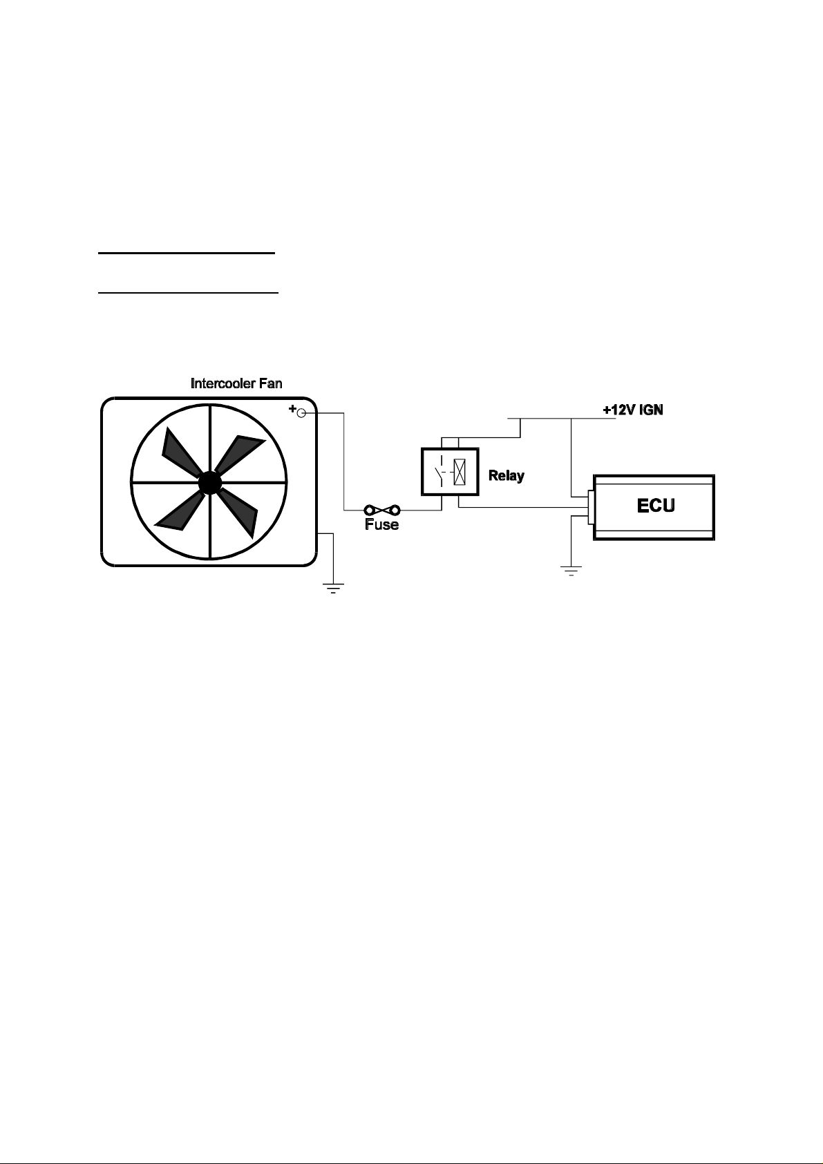
Install the wiring for the thermofan to one of the Auxiliary outputs. This should be done in the
same way as described in figure 17.5 for the Thermofan. Be sure that the relay contacts are
rated higher than the current drawn by the fan.
Run the E6A programming software and go to the Options page. Select the Intercooler Fan
function on the appropriate output and set the two temperatures as required.
Switch On Temperature: The inlet air temperature that must be exceed to switch the fan on.
Switch Off Temperature: The temperature the inlet air must drop below before the fan will
be switched off. This parameter should be at least 5° lower than the Switch On temperature to
prevent the fan from switching in and out repeatedly.
Figure 16.5. Example circuit for an Intercooler Fan.
16.7 Shift Light Illumination (SL)
The E6A can be used to activate a shift light or a piezo buzzer when engine speed exceeds the
programmed activation speed.
To use the shift light function, you will need the following:
- a dashboard lamp or buzzer;
- E6A programming software and cable.
The lamp or buzzer should be wired to +12V on one side, and the other to the ECU. The lamp
used must not draw more than 0.5 amp of current (i.e. a 6 Watt globe). Alternatively, a high
intensity LED may be used. If so, use a series resistor of 330 ohms to limit the current through
the LED to around 40mA.
Once the wiring has been installed, run the E6A programming software and go to the Options
page. Select the Shift Light function on the appropriate output and set the value as desired.
16.8 Auxiliary Fuel Pump (AP)
87
Page 88

Running two fuels pumps continuously, or else a single very large flow-rate pump (if one is
available) means excessive noise and heating of the fuel. A street vehicle with very high
potential output will not need a large fuel supply at all times. The second pump would only be
activated when load demands require that the extra flow be available.
NB: The extra fuel pump cannot be driven directly by the ECU. The ECU can be made to
drive a relay to power the pump.
To use the Auxiliary Fuel Pump function, you must have the following:
- a properly plumbed fuel pump, wired through a relay;
- E6A programming software and cable.
The extra pump must be connected in parallel with the primary fuel pump. Figure 16.6
suggests a possible layout. The check valve is necessary to prevent fuel from being forced in
the wrong direction. Connect the power to the pump via a relay as shown. Either the positive
or negative side may be switched through the relay.
Run the E6A programming software Online and select the Auxiliary Fuel Pump function on the
appropriate output. There are two parameters that define when the Auxiliary Pump will be
switched on.
Load Bar: This is the bar number on the fuel maps which must be exceeded for the extra fuel
pump to be switched on. If you wish to switch the extra fuel pump only by engine speed, set
this to 32.
Engine Speed: The extra fuel pump will turn on when the engine speed exceeds this
parameter. If you wish to switch the pump only by load, set this parameter high.
Run Time: The auxiliary fuel pump will switch on if the engine exceeds the engine speed
and/or the load bar set above. It will then stay on, even after speed and load have dropped
below their respective limits, for a period of time specified by Run Time. A minimum Run
Time of 5 seconds is permitted.
The Auxiliary Fuel Pump will prime with the main fuel pump, but will only run if the engine
condition exceeds either limit. Since there may be a short delay from the time the fuel pump is
switched on to the time the extra fuel becomes available, the Load Bar and Engine Speed
settings above should be set below when that extra fuel is actually needed. The use of a good
quality check valve and fuel pump will reduce the delay time by maintaining pressure in the
secondary line. Nevertheless, the extra fuel will not be instantly available and care should taken
when deciding the switch times. If these values are set too high, the engine may be
momentarily starved of fuel when there is a sudden fuel demand.
88
Page 89

16.9 Anti-Stall Solenoid Control (AS)
A solenoid air valve in the manifold may be used to allow extra air into the engine during
cranking or extremely low rpm. This can aid in starting the engine, or in preventing it from
stalling if engine revs drop too low.
To use this function, you will need the following:
- a suitable solenoid air valve mounted to the manifold;
- E6A programming software and cable.
If the solenoid air valve is too large, the engine may stall because of its opening. The valve
should be of appropriate size to increase the idle speed by several hundred rpm. Wire the
solenoid through the Auxiliary I/O connector. Run the E6A programming software in Online
mode and select the Anti-Stall function on the appropriate output.
There is only one parameter to be set with this function. That is the rpm below which the valve
will be opened. The default setting for this parameter is 500rpm.
16.10 Staging Signal Function (SS)
This function uses an output to indicate when the engine is in the staging section of map, i.e..
when the load has increased beyond the Staging Load Bar in the Identification Page. If
enabled, this signal will operate regardless of whether the ECU is running in Staged Injector
Mode.
NB: The staging signal does not pulse with the other injectors. It switches on and stays
activated while the load is above the staging point.
There are no programmable parameters associated with this function.
16.11 Driver Box (DB3) Staging Signal Function
89
Page 90

This function is similar to the previous Staging Signal, except that the signal is inverted so that
it is compatible with the Haltech DB3 Driver Box, used for controlling extra injectors. There
are no programmable parameters associated with this function.
16.12 Turbo Timer (TT)
When an engine is switched off, oil is no longer being pumped to the turbocharger. This is
common cause of turbo wear if the turbocharger is no allowed to slow down before an engine
is switched off, cause it to spin for an extended time unlubricated. This function controls the
ignition power via relays to keep the engine running for a period of time after the ignition
switch has been turned off.
Care should be taken to make sure the relays are wired correctly, and that an over-ride switch
has been fitted to allow the engine to be switched off manually while the turbo timer is active.
See figure 17.6 for the correct way to wire this output. The ECU detects if the ignition switch
has been turned off via the Auxiliary Input/Output. Therefore, the Auxiliary Input/Output
Function must be selected as Turbo Timer in the Identification.
There are three programmable parameters. The first two are the minimum Air Temp. and the
minimum Coolant Temp. If the inlet air and the coolant temperatures drop below their
respective values, the output will switch off. The last parameter is the Run Time. This is the
maximum time the ECU will allow the engine to continue to run after the ignition switch has
been turned off. If either of the temperature conditions are meet before this time, the output
(and therefore, the engine) will switch off. The Run Time is set to the nearest half minute.
Figure 17.6
NB: When using the Turbo Timer function, the Aux. In/Out Function in the Identification
must be set for Turbo Timer. When using TT, other functions that use the Aux. Input/Output
line can not be used.
90
Page 91

16.13 NOS Switch
This function controls the operation of a NOS system. It does not control the delivery of the
Nitrous Oxide, but simply turns the system on or off in certain conditions. The Nos system
must control the delivery of the nitrous oxide and must also provide extra fuel delivery. The
output is enabled by a switch connected to the Auxiliary Input/Output. Once enabled, if the
conditions stated below are met, the NOS system will be activated. The Auxiliary Input/Output
Function in the Identification must be set to NOS Switch for the function to operate correctly.
There are five adjustable parameters :
Load Bar : If the Fuel Map Bar Number exceeds this value, the NOS system will be
turned off. This is used for turbo engines where the Nos is used to help boost the
turbo. Once on boost, the Nos can be turned off. Normally aspirated engines, on the
other hand, can use Nos at full load, so this value should be set bar 32.
Max. Rpm : If the Rpm exceeds this value the NOS system will be switch off.
Min. Rpm : If the Rpm is below this value the NOS system will not be activated.
Minimum Throttle : The NOS system will be turned on above this value.
Minimum Temp. : The NOS system will not be activated unless the engine coolant
temperature is above this value.
Ignition Retard : The E6A will provide an ignition retard whenever the Nos system is
engaged. The number of degrees retard is set by this field.
NB: When using the Nos function, the Aux. In/Out Function in the Identification must be
set for Nos. When using Nos, other functions that use the Aux. Input/Output line can not be
used.
FOR SAFETY REASONS THE NOS FUNCTION IS ENABLED ONLY AFTER THE
ECU IS ON FOR MORE THAN 2 MINUTES.
91
Page 92

lag Enable
16.14 Anti-Lag Switch
The Anti-Lag switch function allows turbo-charged vehicles to decrease the “lag” associated
with boost when the motor is not under full load.
There are 6 adjustable parameters:
Enabled / Disabled : This either enables or disables this function.
Retard Value : The ignition timing is retarded by this amount when the Anti Lag conditions for operation are met. The valid range for the
Retard value is (1 to 20)° ATDC.
% Inc. Fuel : The percentage of fuel increased during Anti-Lag operation.
The valid range for this function is (1 to 50)%.
Zero TPS ONLY : If the Anti-Lag function is to be used when the Throttle
Position Sensor value is zero then turn this function ON.
Otherwise select OFF.
Zero Inj Time : If the zero TPS only function is ON then this value determines
the amount of fuel injected at zero or no throttle. The valid
range is (1-16) mS.
Throttle Perc : The throttle position value below which Anti-Lag is
operational. The valid range is (5-80)%.
The anti-lag system is enabled by a switch connected to the Auxiliary Input/Output. Once
enabled, if the conditions in the anti-lag parameters are met, the anti-lag system will be
activated. In some systems the switch is activated by the clutch.
To ECU : Aux Out
To ECU : Aux In
Anti-
Switch Position
Closed
Open
WARNING: DO NOT OPERATE ANTI-LAG FOR PROLONGED PERIODS.
EXHAUST AND TURBO TEMPERTAURES RISE WHICH MAY CAUSE ENGINE
DAMAGE.
To Anti-lag valve
Anti-lag
enabled
disabled
92
Page 93

SECTION FIVE
Appendices
Appendix A
Troubleshooting
This Appendix is devoted to trouble shooting problems that may occur during setting up the
E6A on your engine. To use this Appendix, firstly identify the closest symptom or symptoms
from the list below, and then follow the checklist for possible solutions.
A.1 Overview
Control Programme Problems
• The Haltech Programming Software will not load up
• The Haltech Programming Software will not operate in Online mode.
• The Engine Data Page is displaying unusual sensor readings
Starting Problems
• Fuel Pump does not prime when ignition switched on.
• The engine makes no attempt to start
Idling Problems
• The engine will not idle when cold
• The engine idles too slow
• The engine idles too fast
• The engine surges at idle
Light Throttle and Cruising Problems
• Engine will not run at light throttle
Full Power Problems
• Engine dies under full throttle
• Engine surges under full throttle
• Engine lacks power at full throttle
Throttle Response Problems
• Poor throttle response
• Poor throttle response when cold
Cold running problems
• Engine runs poorly when cold
93
Page 94

Fuel Economy problems
• Poor fuel economy - city cycle
• Poor fuel economy - Highway cycle
A.2 Control Programme Problems
Haltech Programming Software will not start up
The Haltech programming software should run on any computer that meets the requirements in
Chapter 3. If, after following the instructions in Chapter 3, the programme will not run, the
most likely cause will be insufficient memory. If this is the case, you must make more free
memory available before running the software.
Do not try running the Haltech software from out of another shell programme - always start
from the DOS prompt. If you are loading a number of TSR (Terminate and Stay Resident)
utilities during bootup, you may need to disable them before running the Haltech software.
Refer to your computer and DOS reference manuals on memory management.
Alternatively, you may make your Haltech disk bootable by placing it in floppy drive A: and
typing:
c:\> sys a:
We recommend that you make a backup of the original disk before trying this. You should then
be able to restart your computer with the disk in drive A:, and the Haltech software will load
and run automatically.
If the software still does not run, and you see the message "Error ### at xxxx:xxxx", record
these numbers (or letters) and contact your Haltech dealer.
Haltech Programming Disk will not run Online
If the Haltech ECU does not respond to the Programming software requesting information,
then the message RECONNECT HALTECH will be displayed. This situation will occur under
the following conditions
• ECU is not powered up
• Programming Cable is not connected
• Incorrect COM port selected - see Chapter 13
• Wrong Programming Disk (i.e. disk does not match ECU)
• Programming Cable is damaged
• Serial port of programming computer is faulty.
If the disk is the wrong version or you suspect that the cable is faulty, contact your Haltech
dealer.
94
Page 95

Engine Data Page Displays Unusual Readings
If the air temperature sensor, or coolant temperature sensor is showing a FAULT condition
then the sensors are either not operating correctly or are disconnected. Using the wiring
diagram of the Haltech E6A Loom check that the sensor wires are not damaged. If the wiring
is OK then contact your Haltech dealer regarding replacement of faulty sensor.
If the Throttle Position Sensor is showing a fault condition then re-calibrate the throttle sensor
and check the wiring
If the Manifold Absolute Pressure Sensor does not read near atmospheric pressure with the
engine off, or if it shows a fault condition, then check that the sensor is connected correctly.
Check that you have the correct model sensor and that the Identification page information has
been set correctly.
If the Engine Speed reading is erratic, the trigger is most likely picking up ignition noise from
incorrect plugs or leads, electrical noise from cooling fans, starter motor, alternator or other
electrical devices in the vehicle.
If the Engine Speed is steady but wrong, check that the Identification page contains the correct
information regarding number of cylinders. Make sure the Multitooth trigger type is not
selected unless the engine has a multitooth wheel. If using a multitooth trigger, make sure the
number of teeth is correctly set for the number of teeth be cam revolution.
If engine parameters are all showing unusual variation, make sure that the ECU is grounded
properly. Also check the engine and chassis grounds to the battery.
A.3 Starting problems
Fuel Pump doesn't prime when ignition switched on
The Haltech E6A will attempt to run the Fuel pump for about 2 seconds just after the ignition
is switched on. The fuel pump relay should be heard clicking in and out with the fuel pump. If
the relay clicks but the fuel pump doesn't work then check the wiring of the fuel pump and the
20A fuse in the fuse block.
Engine makes no attempt to start
Check the following:
• ECU is operating (will communicate Online) during cranking
• Battery voltage and connections
• Fuel Pump runs
• Injector fuse is OK and injectors fire
• Ignition system is operating properly and spark is available
• Ignition timing is correct
If the engine is flooding, reduce the bars in the fuel map that are being used during cranking in
the fuel map, the coolant correction map and the cold prime map.
95
Page 96

If the engine is not receiving enough fuel and increasing those bars does not help, check that
fuel pressure is available and that the injectors operate properly (are cleaned and flow-tested).
A.4 Idling Problems
If the engine will not idle when cold but will when the engine is warm then the coolant
correction map needs to be adjusted.
If the engine idles too fast or too slow, and you are using an Idle Air Control Motor, firstly
check that the Idle Speed Control is enabled, and then lower the target idle setting if necessary.
If not using the idle air control motor then adjust the idle using the idle adjust screw on the
throttle body. Check for any air leaks in the manifold.
Check the ignition timing at idle and adjust if necessary.
If the engine surges or hunts at idle then the mixtures and timing are wrong. Readjust the fuel
maps near idle conditions.
In some circumstances it may be necessary to use the Zero Throttle Map. Consult Chapter 6
[6.2] for information on using the Zero Throttle Map.
A.5 Light throttle and Cruising Problems
If the engine falters under light load then the mixtures might be too lean, check the Fuel Maps.
A.6 Full Power Problems
If the engine gasps under full throttle then the mixture may be too lean. If the engine bogs
down and blows smoke then the mixture is rich. Recheck the fuel maps
If the maps appear to be correct then ensure that the fuel pressure is not falling out of
regulation by using a fuel pressure gauge. Flow test and clean the fuel injectors
In some circumstances it may be necessary to use the Full Throttle Map. Consult Chapter 6
[6.3] for information on using the Full Throttle Map.
A.7 Throttle Response
Throttle response of the E6A is set using the three pairs of throttle pump settings. If the engine
gasps and flat spots (misfires) when the throttle is suddenly opened then the throttle setting is
not high enough or is much too high. If the engine bogs down but continues to run then the
mixture is too rich. Experiment with the throttle pump settings to achieve the optimum.
96
Page 97

The throttle pump coolant factor affects the throttle pump only when coolant correction is
being applied, i.e. before the engine has reached operating temperature. Set the throttle pump
increase and sustain figures only when the engine is warm. Wait until the engine is cold again,
and the coolant correction map has been set for good stable running, before changing the
coolant factor.
A.8 Cold Running Problems
If the engine idles poorly when cold then the coolant map may need adjusting. If the engine is
hunting slightly when cold, then the coolant correction map is just too lean, and so needs a
small amount of enrichment. Slight advance with the coolant temp. can help. If the engine is
difficult to drive when cold, particularly with gear changes, try increasing the coolant
correction factor for the throttle pump.
An engine that will idle when warm, but fails to idle cold unless a tiny amount of throttle is
applied may require idle speed control, with a fast-idle function for when the engine is cold.
The E6A can control an Idle Air Control motor that will perform this function.
A.9 Fuel Consumption
Poor fuel consumption is a result of a too rich mixture. If the fuel consumption in traffic is
poor but the highway consumption is good, then it could be the areas of the map used for
accelerating that need to be leaned out. The throttle pump may also waste fuel if its values are
too high. Also try using the fuel cutoff on deceleration feature.
If the city consumption is fair but highway cruising uses too much fuel then lean out the light
load bars on the 2000 rpm to 3000 rpm maps (This is where most cruising takes place).
If the cold start map is supplying too much fuel on warm-up this will also affect the fuel
consumption of the vehicle.
97
Page 98

Appendix B
The Advanced Features
The Advance Mode of the E6A offers the user extra flexibility in setting the system up for
multiple outputs (i.e. more than one ignition channel and one or two fuel channels). To
understand exactly what is available in the Advanced Mode, a brief description of how the
system and its output work is required.
B.1 The E6A Outputs
The E6A has five outputs, or channels. In Basic Mode, the channels are configured as
follows:
Two outputs drive two solenoid drivers each. These two outputs define the four injector
drivers used for fuel in a standard setup. These two fuel channels are either fired together
(Multipoint Injection Mode) or alternately (Batch Fire Injection Mode). We will call these
channels 1 and 2. Channel 1 is connected in the loom to the outputs marked INJ1 and INJ2.
Channel 2 is connected to INJ3 and INJ4.
Channel 3 is the ignition channel. On a basic setup it would provide the output for an igniter
firing one ignition coil connected to a distributor.
Channels 4 and 5 are the Auxiliary channels. They provide outputs such as Turbo Wastegate,
Thermofans, Shift Light, etc.. The user can select these outputs to be one of several available.
These output are also call Aux Out 1 and Aux Out 2, and are marked similarly on the loom.
In the Advanced Mode, we change the function of these outputs a little to give the extra
abilities. We use the Auxiliary channels to provide more ignition channels or more fuel
channels.
B.2 Direct Fire Ignition
B.2.1 Ignition Outputs
There are two forms of Direct Fire Ignition. One is to have one coil per spark plug (usually
mounted on top of the plug.) Each cylinder is individually controlled by its own coil.
The second method is to use a waste spark. The plugs are paired into companion cylinders
(cylinders with the same TDC but on different strokes). Each coil fires sparks on a pair; one
into the compression stroke, one into the exhaust stroke (the waste spark). Both methods
mean that the distributor can be discarded.
98
Page 99

With either method, the importance of the setup to the E6A is the number of coils. Each coil
needs its own igniter and ignition output. On a four cylinder using waste spark, two coils are
used, and, therefore, two ignition outputs are needed. In this case, channel 4 is used as the
second ignition channel, making it unavailable for auxiliary outputs. The six cylinder with
waste spark is similar. It requires 3 coils and 3 ignition channels. For this setup, channels 4 and
5 become ignition channels 2 and 3 respectively, and neither is available for Auxiliary Outputs.
A V8 becomes a little difficult. It requires 4 coils and 4 ignition outputs, but we have no more
available outputs. Therefore, we take one of the fuel drivers and use it as an ignition channel.
The E6A uses channel 1 (marked on the loom as) for this purpose. This channel becomes
ignition channel 4. There is some trade offs with this though. Multipoint is the only available
injection mode. The batch fire and staged modes are not available. Also, because there are only
two injector drivers left of controlling fuel, an Extra Driver Box (or possibly 2) will be needed
to provide enough power for all the injectors.
Using the same configuration also gives us another possibility. Since there are four ignition
outputs it is possible to use them to control 4 coils on a 4 cylinder. This option is selectable
through the Ignition Setup.
There are some other cylinder configurations to consider. 1, 2 and 3 cylinder engines need 1, 2
and 3 ignition outputs respectively. Alternatively, a two cylinder can use one ignition output
and use a direct fire coil with a waste spark. The Direct Fire Option should not be chosen. This
can only be done if the engine is not odd fire. Five cylinder engines can not run Direct Fire as
they can not use waste spark and therefore need 5 ignition outputs. Also, there are not enough
outputs to run Direct Fire on 10 and 12 cylinder engines.
B.2.2 Synchronising
On a distributed engine the E6A does not need to know the engine position. It is told to
generate a spark which the distributor sends to the correct spark plug. With Direct Fire, the
E6A needs to know engine position so that it knows what coil to trigger next. To do this, the
ECU needs to receive a Synchronisation Event (Sync. Event). One form of Sync Event is
missing teeth on a multitooth wheel. The most common Sync Event though, is a Home trigger.
This trigger needs to occur before the main trigger for cylinder (or coil) one, indicating that the
next main trigger is for cylinder one. This trigger should not occur at the same time as the main
trigger.
When the engine is started, the ECU will not generate a spark until it receives a Sync Event.
After that, the ECU fires each ignition output sequentially until it gets to the last output. It
then expects to receive another Sync Event. If it does not receive a Sync, it will not fire
another spark until it does. If the Sync is received, ECU ignition is set back to coil one and the
sequence continues.
The Home trigger must occur before the main trigger each time coil one is to be fired. For
example, on a four cylinder with waste spark, coil one needs be fired once every revolution.
With 4 coils, though, coil one fires once every two revolutions. A cam trigger would be
required for the Home.
99
Page 100

The Home trigger is wired to the same input as the Road Speed. This means that the Road
Speed input, and consequently the Torque Converter Output, cannot be used with Direct Fire.
B.2.3 Coil Setup
To give an example of how to match up the coils to the ignition outputs, we will use an
example of a V8 with an arbitrary firing order of : 1, 2, 7, 8, 4, 5, 6, 3. The companion
cylinders are the corresponding cylinders in each half. Therefore the companion pairs and their
coil numbers would be : Coil One, cylinders 1 and 4; Coil Two, cylinders 2 and 5; Coil Three,
7 and 6; Coil Four, 8 and 3. The coil numbers then match up with the ignition Channel
numbers. The diagram below shows how the coils would connect up.
Figure B1. Coil layout for V8 with firing order 1, 2, 7, 8, 4, 5, 6, 3.
It is not necessary for coil one to connect to cylinder one. If, for instance, the original Home
trigger occurs before cylinder 6 (not common, but possible) then coil one would need to
connect to cylinder 6. The coil order would still be the same.
B.2.4 Converting Individual Coils to Waste Spark
One way of overcoming the problem of individual coils on 6 and 8 cylinder engine (and 4
cylinders if required) is to pair the cylinders up in the same way, but run 2 igniters (one for
each plug) to one ignition output. For example, on a six cylinder six igniters would be required
but only 3 ignition outputs, which is within the scope of the E6A.
B.2.5 Ignition Outputs
The E6A will always use it outputs in the same order. It will use up to 4 outputs, and what
outputs it does not use are available for other purposes. The output order is :
100
 Loading...