

Page 1
Instruction Manual
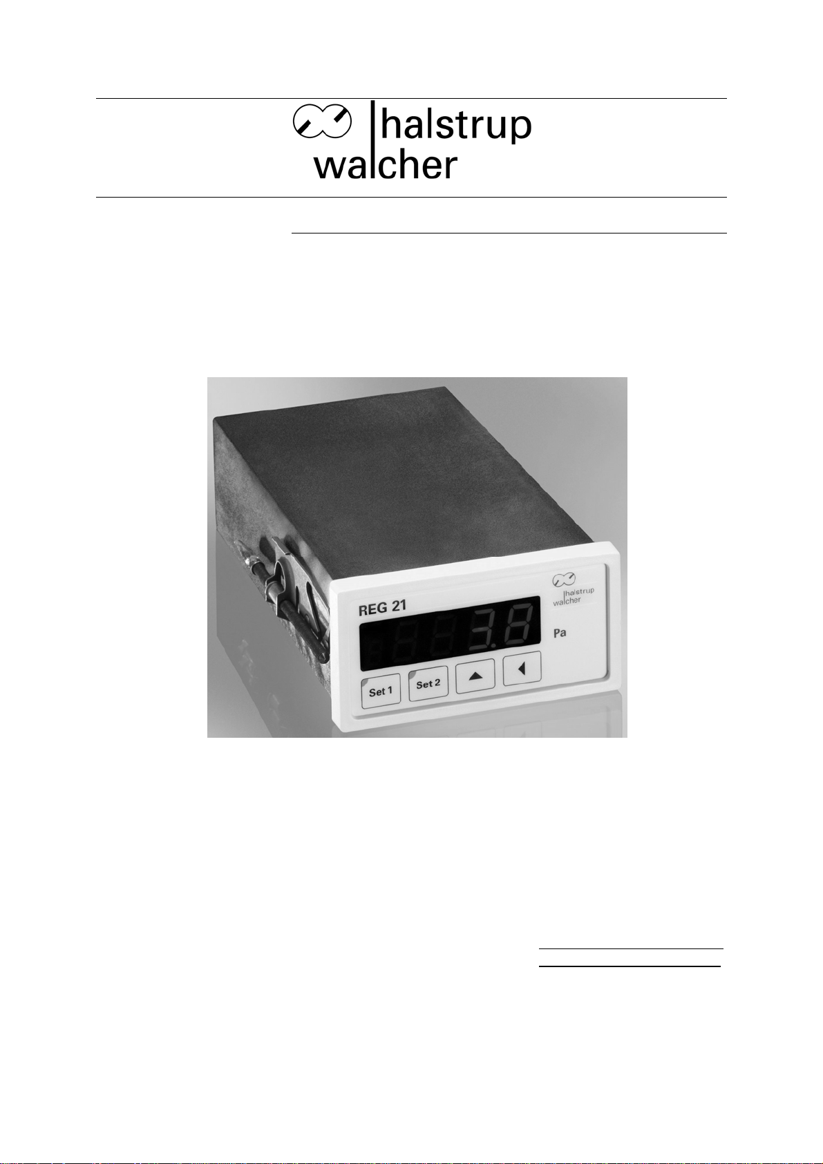
REG 21 Pressure
Regulator
Document 7100.003674 Version 2.1 05/2009
halstrup-walcher GmbH
Stegener Straße 10
D-79199 Kirchzarten
Germany
Phone: +49 (0) 76 61/39 63–0
Fax: +49 (0) 76 61/39 63–99
E-Mail: info@halstrup-walcher.com
Internet: www.halstrup-walcher.com
Page 2

Instruction Manual REG 21
Table of Contents
1 Safety precautions ................................................................................................................ 5
1.1 Appropriate use.................................................................................................................. 5
1.2 Shipping, assembly, electrical connections and start-up.................................................... 5
1.3 Troubleshooting, maintenance, repairs, disposal............................................................... 5
1.4 Symbols ............................................................................................................................. 6
2 Instrument description........................................................................................................... 7
3 Start-up ................................................................................................................................. 7
3.1 Features ............................................................................................................................. 7
3.1.1 Inputs and outputs .......................................................................................................... 7
3.1.2 Display elements............................................................................................................. 8
3.1.3 Keypad............................................................................................................................ 8
3.2 User functions .................................................................................................................... 9
3.3 Device parameters...........................................................................................................10
3.4 Switching behaviour.........................................................................................................11
3.5 Zero-point calibration ....................................................................................................... 12
3.5.1 Sequence of zero-point calibration steps...................................................................... 12
3.6 Overload protection.......................................................................................................... 12
4 Identification ........................................................................................................................ 13
4.1 Included in shipment ........................................................................................................13
4.2 Product labelling .............................................................................................................. 13
4.3 Models ............................................................................................................................. 13
5 Electrical connections and installation................................................................................. 14
5.1 Installation........................................................................................................................ 14
5.2 Instrument connections.................................................................................................... 14
5.2.1 Pressure ports............................................................................................................... 14
5.2.2 Electrical connections ................................................................................................... 15
5.2.3 Option light emitting diodes (LED) ................................................................................ 15
6 Start-up ............................................................................................................................... 16
6.1 Setting parameters........................................................................................................... 17
6.1.1 Overview of parameter setting functions and parameters............................................. 17
6.1.2 Launching a parameter setting function........................................................................ 18
6.2 Setting parameters........................................................................................................... 18
6.2.1 Notes on setting switching value parameters................................................................ 20
7 Troubleshooting .................................................................................................................. 21
8 Technical data..................................................................................................................... 22
2
Page 3

Instruction Manual REG 21
9 Dimension drawings...........................................................................................................24
3
Page 4

Instruction Manual REG 21
Purpose of instruction manual
This instruction manual describes the features of the REG 21 pressure regulator and
provides guidelines for its use.
Improper use of this instrument or failure to follow these instructions may cause injury
or equipment damage. All individuals responsible for operating this instrument must
therefore be properly trained and aware of the hazards, and must carefully follow
these operating instructions and the safety precautions detailed within. Contact the
manufacturer if you do not understand any part of this instruction manual.
Handle this manual with care:
It must be readily available throughout the lifecycle of the instrument.
It must be provided to any individuals who assume responsibility for operating the
instrument at a later date.
It must include any supplementary materials provided by the manufacturer.
The manufacturer reserves the right to continue developing this instrument model
without documenting such development in each individual case. The manufacturer
will be happy to determine whether this manual is up-to-date.
Conformity
This instrument corresponds to the state of the art and meets all legal requirements
set forth in EC directives as evidenced by the CE label.
© 2002
The manufacturer owns the copyright to this instruction manual. This manual contains
data, instructions and drawings pertaining to the features and usage of this
instrument; copying this manual in part or in full or distributing it to third parties is
prohibited.
4
Page 5

Instruction Manual REG 21
1 Safety precautions
1.1 Appropriate use
The REG 21 pressure regulator is designed for measuring, displaying, monitoring and
regulating positive and negative overpressures and differential pressures of nonaggressive, gaseous media.
Always observe the operating requirements—particularly the permissible supply
voltage—indicated on the rating plate and in the “Technical data” section of this
manual.
The instrument may only be handled as indicated in this manual. Modifications to the
instrument are prohibited. The manufacturer is not liable for damages caused by
improper use or failure to follow these instructions. Violations of this type render all
warranty claims null and void.
1.2 Shipping, assembly, electrical connections and start-up
Do not close the pressure input ports when shipping, as changes in barometric
pressure could damage instruments with low measuring ranges.
Only technical personnel who are appropriately trained and authorized by the
operator of the facility may assemble the instrument and set up its electrical
connections.
The instrument may only be operated by appropriately trained individuals who have
been authorized by the operator of the facility.
Pressurized air or breath is not to be used for performance tests, as this could
damage instruments with low measurement ranges.
Measurement errors may occur if the instrument is not kept protected from sunlight.
Specific safety precautions are given in individual sections of this manual.
1.3 Troubleshooting, maintenance, repairs, disposal
The individual responsible for the electrical connections must be notified immediately
if the instrument is damaged or if errors occur.
This individual must take the instrument out of service until the error has been
corrected and ensure that it cannot be used unintentionally.
Always unplug the power cord before opening the instrument!
This instrument requires no maintenance.
Only the manufacturer may perform repairs that require the housing to be opened.
5
Page 6
Instruction Manual REG 21
The electronic components of the instrument contain environmentally hazardous
materials and materials that can be reused. For this reason the instrument must be
recycled in accordance with the environmental guidelines of the jurisdiction in
question once it has been taken permanently out of service.
1.4 Symbols
The symbols given below are used throughout this manual to indicate instances when
improper operation could result in the following hazards:
WARNING! This warns you of a potential hazard that could lead to bodily injury up
to and including death if the corresponding instructions are not followed.
WARNING: This warns you of a potential hazard that could lead to significant
property damage if corresponding instructions are not followed.
INFORMATION: This indicates that the corresponding information is important
for operating the instrument properly.
6
Page 7
Instruction Manual REG 21
2 Instrument description
The REG 21 pressure regulator measures differential pressures between its two
pressure ports, which lead to two chambers of a pressure measurement capsule.
Pressure is measured via a beryllium bronze membrane spring, which is displaced by
the pressure difference between the two chambers. Inductive displacement
transducers measure membrane deflection without contacting the membrane. The
instrument has no frictional parts or parts subject to mechanical wear, and performs
the following tasks:
Displays the measured value
Provides the voltage (current is also an option) proportional to the measured value.
Its two switching outputs make it suitable for use as either a two-point or a three-point
controller
The following are some additional features worth highlighting:
Overload protection
Adjustable switching hysteresis
High level of sensitivity
High level of accuracy and long-term stability
Automatic zero-point correction
Low temperature dependence
3 Start-up
3.1 Features
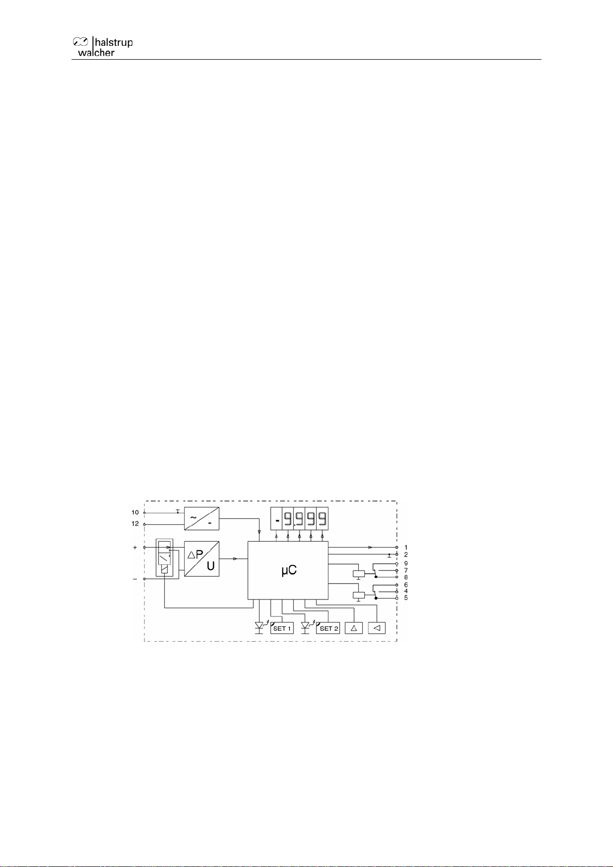
3.1.1 Inputs and outputs
power supply
pressure
ports
Fig. 1: basic circuit diagram
Power supply: Depending on the model, the power is supplied as either 230 V-AC,
155 V-AC, 24 V-AC or 24 V-DC. The details of the supply voltage are given on the
rating plate.
Pressure ports: (-) port: reference pressure; (+) port: pressure to be measured.
The measurement range is given on the rating plate.
Analogue output: The instrument produces a voltage output proportional to the
measured pressure. Output is in the range of 0...10 V (ranges of -5…+5 V, 4...20
mA or 0...20 mA are optional). The spread of the analogue output values is
proportional to the measurement range. The type of analogue output is indicated on
the rating plate.
analog output
switching output 1
switching output 2
7
Page 8
Instruction Manual REG 21
Switching outputs 1 and 2: The instrument comes equipped with 2 relay outputs (2
transistor outputs are also an option). The type of switching output is indicated on
the rating plate. Switching outputs are triggered when values exceed and/or fall
below switch-on and switch-off values. See section 3.4 for a more detailed
description of switching behaviour. The instrument utilizes changeover relays and
bipolar NPN transistors, making it possible to create either open-collector or openemitter circuits.
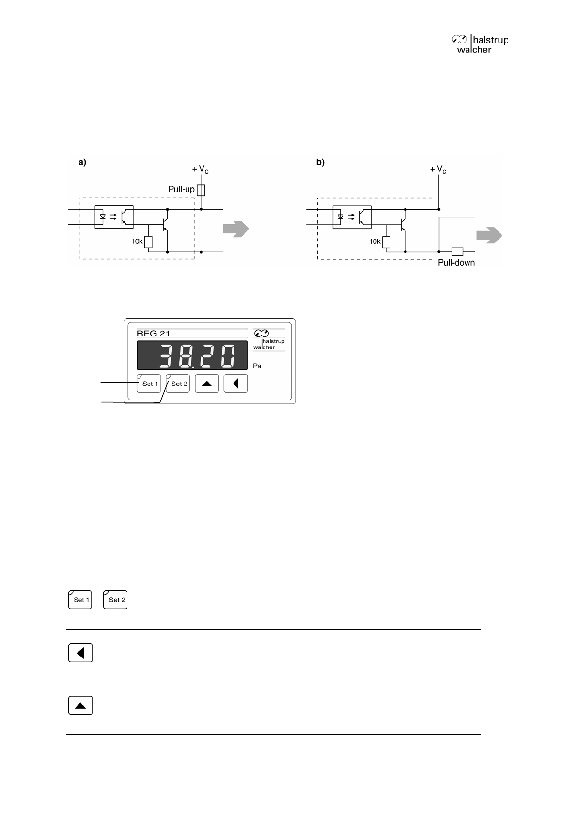
digital
input
Fig. 2 Transistor output (optional) a) open-collector circuit b) open-emitter circuit
3.1.2 Display elements
LED 1
LED 2
Fig. 3 Front view of the instrument
Display: The display shows the measured differential pressure or overpressure in
the units indicated on the housing next to the display. Positive values are displayed
as is; negative values are indicated by a preceding minus sign.
LED 1: LED 1 shows the status of switching output 1 and is illuminated whenever
the switch-on value exceeds or falls below that set for switching output 1 (see fig. 5).
LED 2: LED 2 shows the status of switching output 2 in a way analogous to that of
output 1.
digital
input
,
Table 1
3.1.3 Keypad
The instrument is set by means of 4 keys, whose functions are described in the
following:
Set key:
Call up and exit parameter setting and display functions
Save parameters
Enter key:
Begin and end settings
Select decimal places and +/- sign
Select key:
Select values or parameters
Set numerical values
8
Page 9

Instruction Manual REG 21
3.2 User functions
User functions include setting device parameters, displaying switching output
parameters and manually performing a zero-point calibration.
Users call up these functions by pressing the set keys; the specific function called up
depends on whether the keys are pressed individually or in combination, and for how
long they are pressed. Moving decimal points indicate that the instrument is no longer
displaying measured values (see fig. 7).
Function
Key sequence Process flow
parameter setting
basic settings
see section 6.1
press both and
hold for <2 s*
setting parameters for
switching output 1
setting parameters for
switching output 2
hold for >2 s**
hold for >2 s**
see section 6.1
see section 6.1
display functions
displaying parameters
for switching output 1
hold for <2 s*
Values for switching on and off as well
as the switching direction (see section
3.4) are displayed one after the other.
The display then returns to the
measured value.
displaying parameters
for switching output 2
hold for <2 s*
Values for switching on and off as well
as the switching direction (see section
3.4) are displayed one after the other.
The display then returns to the
measured value.
Other functions
Start manual zero-point
calibration
depress
The zero-point calibration is performed
automatically. The display then returns
to the measured value.
simultaneously and
hold for >2 s**
* hold for <2 s: depress the key(s) until the decimal points on the measured value
display begin to move (see fig. 7 (2))
** hold for > 2 s: depress the key(s) until the “PPP” release code appears (see fig. 7
(3)).
Table 2 User functions for the REG 21 pressure regulator
9
Page 10

Instruction Manual REG 21
3.3 Device parameters
Several parameters are available for adapting instrument operation to a number of
different applications. Section 6.1 describes how to set parameters; table 3 provides
an overview of available parameters.
Parameter
Description
basic settings
time constant the amount of time required for the display, analogue output and (if
the corresponding parameters are set) switching outputs to
respond to changes in pressure
brightness display brightness
zero-point
automatic or manual zero-point calibration options
calibration
relay output 1
switch-on value pressure threshold value that activates the switching output, see
section 3.4
switch-off value pressure threshold value that disables the switching output, see
section 3.4
switch direction parameter for selecting one of the two possible directions between
the two relay/transistor output states, see section 3.4
switching output 2 (analogous to switching output 1)
switch-on value see above
switch-off value see above
switch direction see above
Table 3 parameters for the REG 21 pressure regulator
10
Page 11

Relay 1
LED 1 “on”
LED 1 “off”
Instruction Manual REG 21
3.4 Switching behaviour
The behaviour of the switching outputs is determined by the settings for the switchon, switch-off and switch direction parameters.
Both switching outputs can each be used individually as two-point controllers or in
combination as three-point controllers. The following diagrams illustrate this feature
and define the behaviour of the switching outputs.
Relay1
hysteresis
Relay 1
LED 1 “on”
LED 1 / 2 “off”
LED 2 “on”
Relay 2
p: pressure
p1: switch-on value,
relay 1
p2: switch-off value,
relay 1
p3: switch-on value,
relay 2
p4: switch-off value,
relay 2
The numbers indicate the terminal assignment (see fig. 6)
Fig. 4 Behaviour of switching outputs; switch direction = “0” a), b) relay 1 as a twopoint controller c), d) relay 1 and 2 in combination as a three-point controller
The following are the equivalents for transistor outputs:
If the “switch direction” parameter is set to “1,” the switching output behaviour will be
reversed. The following are transposed in fig. 4:
Relay1
Relay2
output states
relay 1
“blocking transistor”
“conducting transistor”
“blocking transistor” “conducting transistor”
output states
relay 2
11
Page 12

Instruction Manual REG 21
3.5 Zero-point calibration
The instrument’s zero point can be calibrated either automatically or manually; the
type of calibration is determined by the “zero-point calibration” parameter setting (see
section 6.1)
If this parameter is set to “automatic zero-point calibration,” the zero point will be
calibrated automatically as soon as the instrument is switched on and then again
15 minutes later. A calibration will then be performed every 60 min.
If this parameter is set to “manual zero-point calibration,” the automatic zero-point
calibration feature is suppressed.
The zero point will be calibrated any time the manual zero-point calibration feature is
triggered (see table 2)—even if the zero-point calibration parameter is set to
automatic.
The zero point can only be calibrated manually on instrument models with no
bypass valve (see section 4.3).
3.5.1 Sequence of zero-point calibration steps
When calibrating the zero point, a valve briefly closes both pressure ports for six
seconds (∆p = 0).
The instrument then checks for 3 seconds to determine whether the deviation from
zero is within the permissible range. If not, e.g., if the pressure measurement
capsule has been overloaded and damaged, the instrument returns error message
E004.
If the deviation is within the permissible range, the zero point will be measured for
an additional 3 seconds in order to obtain a mean value.
After opening the bypass valve, the instrument returns to measurement mode. Each
measured value is then corrected by the stored zero-point deviation value (offset
value).
Pressure cannot be monitored during zero-point calibration; instead, the most
recently measured value prior to calibration is read out and displayed.
3.6 Overload protection
Only available for instrument models with a bypass valve (see section 4.3)
This valve, which is bypassed during the zero-point calibration process, performs an
additional function: it briefly closes the pressure input ports as soon as the pressure
(measured differential pressure value) is 50% higher than the nominal pressure (final
value of the measurement range).
12
Page 13

Instruction Manual REG 21
4 Identification
4.1 Included in shipment
The instrument model ordered
This instruction manual
4.2 Product labelling
The rating plate provides the following information:
measurement range
type of analogue output
precision class
supply voltage
number and type of switching outputs
product number
the CE emblem
The second label indicates the pin assignment.
4.3 Models
The following instrument models are available:
measurement ranges:
analog outputs: 0 ... 10 V -5 ... 5 V 0 ... 20 mA 4 ... 20 mA
power supply: 230 V-AC 115 V-AC 24 V-AC 24 V-DC
switching outputs:
0 ... 50 Pa to 0 ... 100 kPa
2 relays 2 transistors
zero-point calibration
and overload protection
Table 4
bypass valve
(automatic zero-point
calibration and overload
protection available)
13
no bypass valve
(automatic zero-point
calibration and overload
protection not available)
Page 14

Instruction Manual REG 21
5 Electrical connections and installation
5.1 Installation
The instrument should be installed in a control panel with a rectangular
recess (92 + 0.8 mm x 45 + 0.6 mm) using the installation parts included
in the shipment.
5.2 Instrument connections
5.2.1 Pressure ports
Connect tubing ( 6,5 mm) for reference pressure at the (-) port.
Connect tubing ( 6,5 mm) for measured pressure at the (+) port.
pressure ports
terminal strip
Fig. 5 rear view of the REG 21 pressure regulator
14
Page 15

Instruction Manual REG 21
5.2.2 Electrical connections
WARNING! The instrument is available in a number of different models. The
model is identifiable by the features described in section 4.2 and indicated on
the rating plate and on the second housing label. The model must be
identified before making any electrical connections.
WARNING! RISK OF ELECTRICAL SHOCK! Do not attempt to make any
electrical connections unless the cables attached to both switching outputs
are at zero potential and the power supply has been switched off.
The instrument is operates with a floating ground
Set up the electrical connections as indicated on the housing label or in fig. 6.
Relay 1 Relay 2
analog
output
a.
switching
output 2
switching
output 1
power
supply
230 V-AC
50...60 Hz
(standard)
b.
Fig. 6 Pin assignment for terminal strip (from fig. 5):
a. standard unit with 24 V / 115 V-AC options;
b. 24 V-DC option;
c. with optically coupled transistor output (output 1)
5.2.3 Option light emitting diodes (LED)
Pin assignment for terminal for LED
1 – Cathode(-) LED A
2 – Cathode(-) LED B
3 – Cathode(-) LED C
4 – not connected
4 3
5
2 1
5 – common anode(+)
transistor output 2 is
similarly run through
terminals 4 and 5.
c.
15
Page 16

Instruction Manual REG 21
6 Start-up
Switch on unit by connecting the power supply.
The instrument will automatically execute the following sequence of steps:
The unit will run a check, causing all display segments to light up for 2 seconds.
Both outputs are switched off and the corresponding LED goes dark.
Basic settings are automatically checked for plausibility. If they fail, the
instrument generates an error message (see section 7).
The zero point is then calibrated if this function is part of the instrument’s
program. If zero point lies outside of the permissible range, the instrument
generates an error message (see section 7).
Transition to monitoring and display mode:
Displays current pressure
Reads out an analogue value proportional to the pressure
Controls switching outputs in keeping with set parameters
Displays output states with LED
Setting instrument parameters as detailed in section 6.1.
After its parameters have been set, the instrument is in monitoring and display mode, in
which it can perform its measurement, control and monitoring functions.
16
Page 17

Instruction Manual REG 21
6.1 Setting parameters
If parameter mode is not released within 5 s of calling up a parameter
setting function, the instrument returns to monitoring and display mode.
Press either of the set keys ( or ) to exit parameter mode while
setting parameters (prior to concluding the session by depressing the enter
key
).
The instrument will return to monitoring and display mode if no parameters
are entered within 30 s of entering parameter mode.
The original parameters will not be affected in either of these cases.
While in parameter mode, the instrument will continue to monitor pressure and
control the switching outputs and analogue outputs.
WARNING! Hysteresis is critical for all switching values (see fig. 5) in order to
prevent the relay from “fluttering” or the transistors from periodically switching
on/off.
6.1.1 Overview of parameter setting functions and parameters
Parameter Parameter ID Options Default
values
basic settings:
depress both keys;
function
hold for <2 s*
time constant
parameter
n 1, n 2, n 5, n 10
F 1, F 2, F 5, F 10
F 1
1, 2, 5, 10: time constants in s
n: time constants apply to display,
analogue output and switching
outputs
F: time constants apply to display
and analogue output; switching
outputs will be triggered 20 ms
later
brightness
unitless value of 1…15
5
zero-point
calibration
switching output 1
switch-on
value
AU: automatic zero-point
calibration
nor
nor: manual zero-point calibration
hold for >2 s**
entire measurement range
35 %
17
Page 18

Instruction Manual REG 21
switch-off
value
switch direction
switching output 2:
switch-on
entire measurement range
0, 1 0
hold for >2 s**
entire measurement range
value
switch-off
value
switch direction
entire measurement range
0, 1 0
* hold for <2 s: depress the key(s) until the decimal points on the
measured value display begin to move (see fig. 7 (2))
** hold for > 2 s: depress the key(s) until the “PPP” release code appears
(see fig. 7 (3)).
Table 5
6.1.2 Launching a parameter setting function
(see fig. 7)
Call up the desired parameter function as indicated in table 5 (1).
25 %
50 %
10 %
Enter parameter mode by pressing the following keys in sequence:
“Function and parameter ID” will appear (5).
Example: Calling up the “basic settings” parameter function
measured
value display
(1)
press both and
hold for <2 s
moving decimal
points
display
automatically
request for confirmation
(flashing)
(4)
press one after the
other in sequence
Fig. 7
6.2 Setting parameters
Use the following procedure (starting from “function and parameter ID”) to set
parameters (see fig. 8).
Press
to select the parameter to be changed (0).
parameter
(0...2)
“function and
parameter ID”
, , (4).
function
(0...2)
Press the enter key
to open the parameter settings dialog (1).
18
Page 19

Instruction Manual REG 21
(0)
The display shows the value currently set for the parameter (2).
parameter
time constant
brightness
type of zero-
point calibration
display
Press
Press the enter key
(multiple times) to select the desired value (3).
to confirm the selected value (4).
Press one of the set keys ( or ) to save the value (5).
The instrument will display the function and parameter ID for the next parameter (6).
Set the remaining parameters in the same way (7).
Example: Setting the “basic settings” parameters
(1)
(2)
(0)
(6)
(3) (4)
multiple times
desired time
constant value
flashing
display
(5)
(6)
save
(7)
(7)
Fig. 8
19
Page 20

Instruction Manual REG 21
(6)
6.2.1 Notes on setting switching value parameters.
Switching values can be entered as decimal figures; each place must be set
individually, proceeding as follows and beginning with the “function and parameter
code” (see fig. 9):
Press the enter key
to open the parameter settings dialog (1).
The current value is displayed; the numbers of the final decimal place will be
flashing (2).
Continue as follows until you have reached and set the +/- place:
Press
to set the flashing digit (or +/- sign) (3).
Press the enter key
to return to the decimal places (4).
Press the enter key
to complete the setting process (5).
Press one of the set keys (
or ) to save the values (6).
The instrument will display the function and parameter ID for the next parameter (7).
Example: Setting the switch-on value for switching output 1
(1)
(2)
(4)
flashing
(3)
multiple times
(3)
flashing
(4)
(5)
flashing flashing
(3)
multiple times
(7)
flashing
Fig. 9
flashing
flashing
display
save
20
Page 21

Instruction Manual REG 21
7 Troubleshooting
The instrument recognizes the following problems and responds by returning an error
message:
Error
message
Problem Cause Corrective Action
E003 overloaded
pressure
measurement
capsule
E004 pressure
measurement
capsule is
pressurized during
zero-point
calibration
Table 6
pressure too high send the instrument to the
manufacturer for repair
pressure has not been
disconnected
defective pressure
measurement capsule
reduce pressure
send the instrument to the
manufacturer for repair
21
Page 22

8 Technical data
Measurement data
Instruction Manual REG 21
measurement ranges
measurement principle inductive
change in volume 0.1…0.3 mL
overload capacity 200x (for measurement ranges < 2.5 kPa)
600 kPa (for measurement ranges > 2.5 kPa)
linearity ± 1%
± 0.5 % (optional for measurement ranges > 250 Pa)
temperature-dependent drift in
measured values
temperature-dependent drift in the
zero point
zero-point drift over time 0.5 %/year
Ambient conditions
medium air, all non-aggressive gases
operating temperature +10° to +50°C
storage temperature -10° to +70°C
relative humidity 0 ... 80 %
0 ... 50 Pa to 0 ... 100 kPa;
see rating plate
0.04% / K (+10° to +50°C)
0.04% / K (+10° to +50°C)
EMC standards EN 55011; EN 61000-4-3, EN 61000-4-6
conformity
Electrical data
power consumption 3 VA
supply voltage options
standard 230 V-AC, +6 % / -15 % (50...60 Hz)
(optional) 24 V-AC, 115 V-AC, +6 % / -15 % (50…60 Hz)
(optional) 24 V-DC, +20 % / -15 %
analogue output
standard
(optional) -5 ... 5 V; 0 ... 20 mA; 4 ... 20mA
time constant 1 sec. (standard), 2.5 and 10 s may be set by user
switching outputs
standard 2 floating changeover relays; up to 230 V-Ac (50/60
(optional) 2 bipolar NPN transistors; UCE < 50 V; IC < 200 mA,
declaration of conformity available upon
request
0..10 V (RL ≥2 kΩ)
Hz), 6 A w/ ohmic load
floating
time constant 20 ms (standard), 1,2,5 and 10 s may be set by user
electrical connections 12-pin terminal strip
connected cross-sections 0.5 ... 2 mm2
22
Page 23

Instruction Manual REG 21
Physical data
pressure port 2 pressure ports, Ø = 6.5 mm
housing material glass reinforced Noryl
mounting orientation horizontal
Table 7
23
Page 24

9 Dimension drawings
switch panel housing
Fig. 10 housing dimensions
Instruction Manual REG 21
24
 Loading...