

Page 1

Instruction Manual
PSx3xxDP
halstrup-walcher GmbH
Stegener Straße 10
D-79199 Kirchzarten, Germany
Phone: +49 (0) 76 61/39 63–0
Fax: +49 (0) 76 61/39 63–99
E-Mail: info@halstrup-walcher.com
Internet: www.halstrup-walcher.com
Document 7100.003964 03/2017
Page 2

PSx3xxDP Instruction Manual
2
Table of Contents
1 Purpose of instruction manual .......................................................................................... 5
2 Conformity .......................................................................................................................... 5
3 Safety precautions ................................................................ ............................................. 6
3.1 Appropriate use ................................................................................................................ 6
3.2 Shipping, assembly, electrical connections and start-up ................................................... 6
3.3 Troubleshooting, maintenance, repairs, disposal .............................................................. 6
3.4 Symbols............................................................................................................................ 7
4 Instrument description ...................................................................................................... 8
4.1 Functions .......................................................................................................................... 8
4.2 Assembly .......................................................................................................................... 8
4.3 Pin assignment ................................................................................................................. 9
4.4 Setting the device address and terminating resistors ...................................................... 10
4.5 LED status ...................................................................................................................... 10
4.6 Using the bus to set the address .................................................................................... 11
4.7 Using the parameter module to set the address (firmware version 8) ............................. 11
5 Jog key operation ............................................................................................................ 12
5.1 Connecting the keyboard ................................................................................................ 12
5.2 Using the control unit to activate the jog keys ................................................................. 12
5.3 Direct positioning using the jog keys ............................................................................... 12
5.4 Incremental manual operation ........................................................................................ 12
5.5 Incremental operation ..................................................................................................... 12
6 Start-up ............................................................................................................................. 13
6.1 Setting the reference position ......................................................................................... 13
6.2 Positioning sequence...................................................................................................... 13
6.3 Positioning sequence (without reference loop)................................................................ 13
7 Interface ............................................................................................................................ 14
7.1 Status byte configuration ................................................................................................ 14
7.1.1 Target position reached............................................................................................... 14
7.1.2 Drive running ............................................................................................................... 14
7.1.3 Motor supply voltage OK ............................................................................................. 15
7.1.4 Ready ......................................................................................................................... 15
7.1.5 Hardware error ............................................................................................................ 15
7.1.6 Positioning run aborted ............................................................................................... 15
7.1.7 Jog key, down ................................................................ ............................................. 15
7.1.8 Jog key, up.................................................................................................................. 15
7.1.9 Temperature too high .................................................................................................. 15
7.1.10 Drag error ................................................................................................................ 16
7.1.11 Invalid target/parameter value ................................................................................. 16
7.1.12 Positioning error ...................................................................................................... 16
7.1.13 Manual rotation ........................................................................................................ 16
7.1.14 No supply voltage available to motor ....................................................................... 16
7.1.15 Upper range limit ..................................................................................................... 16
7.1.16 Lower range limit ..................................................................................................... 16
7.2 Actual position .............................................................................................................. 16
7.3 Control byte configuration ............................................................................................... 17
7.3.1 Confirmation ................................................................................................................ 17
Page 3

PSx3xxDP Instruction Manual
3
7.3.2 Release bit .................................................................................................................. 17
7.3.3 Manual run release ..................................................................................................... 17
7.3.4 Run with no reference loop ......................................................................................... 17
7.3.5 Set value for reference position ................................................................................... 17
7.3.6 Set and save reference position .................................................................................. 18
7.3.7 Accept and proceed to position ................................................................................... 18
7.3.8 Manual run, down........................................................................................................ 18
7.3.9 Manual run, up ............................................................................................................ 18
7.4 Target position ................................................................................................................ 18
7.5 Parameters ..................................................................................................................... 18
7.5.1 Direction of rotation ..................................................................................................... 19
7.5.2 Direction of travel ........................................................................................................ 20
7.5.3 Position correction ....................................................................................................... 20
7.5.4 Jog key operation ........................................................................................................ 20
7.5.5 Hardware resolution .................................................................................................... 20
7.5.6 Software resolution ..................................................................................................... 20
7.5.7 Positioning window ...................................................................................................... 20
7.5.8 Max. run distance, positive .......................................................................................... 21
7.5.9 Max. run distance, negative ........................................................................................ 21
7.5.10 Target rpm, positioning run ...................................................................................... 21
7.5.11 Target rpm, manual run ........................................................................................... 21
7.5.12 Max. rpm, left ........................................................................................................... 21
7.5.13 Max. rpm, right......................................................................................................... 21
7.5.14 Max. torque ............................................................................................................. 21
7.5.15 Max. torque, left ....................................................................................................... 21
7.5.16 Max. torque, right ..................................................................................................... 21
7.5.17 Max. starting torque ................................................................................................. 21
7.5.18 Duration of starting torque ....................................................................................... 21
7.5.19 Holding torque ......................................................................................................... 22
7.5.20 Drag error ................................................................................................................ 22
7.5.21 Min. rpm for detecting an obstacle ........................................................................... 22
7.5.22 Time required to detect an obstacle ......................................................................... 22
7.5.23 Wait time between runs ........................................................................................... 22
7.5.24 Min. supply voltage .................................................................................................. 22
7.5.25 Filter value for voltage monitoring ............................................................................ 22
7.5.26 Loop length .............................................................................................................. 23
7.5.27 Jog key increment size ............................................................................................ 23
7.5.28 Jog key pause ......................................................................................................... 23
7.5.29 Factor for ramp length ............................................................................................. 23
7.5.30 Limiting temperature ................................................................................................ 23
7.5.31 Reference position MSW ......................................................................................... 23
7.5.32 Reference position LSW .......................................................................................... 23
7.5.33 Production date ....................................................................................................... 23
7.5.34 Serial number .......................................................................................................... 23
7.5.35 Device type .............................................................................................................. 24
7.5.36 Software version ................................................................................................ ...... 24
7.5.37 Hardware version .................................................................................................... 24
7.5.38 Device temperature ................................................................................................. 24
7.5.39 Actual rpm ................................ ................................................................ ............... 24
7.5.40 Max. actual torque (current) ..................................................................................... 24
7.5.41 Run time MSW ........................................................................................................ 24
7.5.42 Run time LSW ......................................................................................................... 24
7.5.43 Drag position ........................................................................................................... 24
7.5.44 Motor supply voltage ............................................................................................... 24
7.5.45 Motor current ........................................................................................................... 24
7.5.46 Supply voltage for control unit .................................................................................. 24
7.5.47 Error code ................................................................................................................ 25
Page 4

PSx3xxDP Instruction Manual
4
7.6 Changing parameter values ............................................................................................ 25
8 Backing up parameter data and the error memory ........................................................ 26
9 Technical data .................................................................................................................. 27
9.1 Drive speed and torque .................................................................................................. 27
9.2 Drive speed and torque PSE34xx ................................................................................... 28
9.3 Ambient conditions ......................................................................................................... 29
9.4 Electrical data ................................................................................................................. 29
9.5 Physical data .................................................................................................................. 30
Page 5
PSx3xxDP Instruction Manual
5
1 Purpose of instruction manual
This instruction manual describes the features of the PSx 3xxDP positioning systems and
provides guidelines for their use.
Improper use of these instruments or failure to follow these instructions may cause injury
or equipment damage. All individuals responsible for operating these instruments must
therefore be properly trained and aware of the hazards, and must carefully follow these
operating instructions and the safety precautions detailed within. Contact the
manufacturer if you do not understand any part of this instruction manual.
Handle this manual with care:
It must be readily available throughout the lifecycle of the instruments.
It must be provided to any individuals who assume responsibility for operating the
instrument at a later date.
It must include any supplementary materials provided by the manufacturer.
The manufacturer reserves the right to continue developing this instrument model without
documenting such development in each individual case. The manufacturer will be happy
to determine whether this manual is up-to-date.
2 Conformity
This instrument corresponds to the state of the art and meets all legal requirements
set forth in EC directives as evidenced by the CE label.
© 2006, 2007, 2014, 2015, 2016, 2017
The manufacturer owns the copyright to this instruction manual. This manual contains
data, instructions and drawings pertaining to the features and usage of these instruments;
copying this manual in part or in full or distributing it to third parties is prohibited.
Page 6

PSx3xxDP Instruction Manual
6
3 Safety precautions
3.1 Appropriate use
Positioning systems are especially suitable for automatically setting tools, stops or
spindles for wood-processing equipment, packing lines, printing equipment, filling units
and other types of special machines.
PSx3xxDP positioning systems are not stand-alone instruments and may only be
used if coupled to another machine.
Always observe the operating requirements – particularly the permissible supply voltage –
indicated on the rating plate and in the “Technical data” section of this manual.
The instrument may only be handled as indicated in this manual. Modifications to the
instrument are prohibited. The manufacturer is not liable for damages caused by improper
use or failure to follow these instructions. Violations of this type render all warranty claims
null and void.
3.2 Shipping, assembly, electrical connections and start-up
Only technical personnel who are appropriately trained and authorized by the operator of
the facility may assemble the instrument and set up its electrical connections.
The instrument may only be operated by appropriately trained individuals who have been
authorized by the operator of the facility.
Specific safety precautions are given in individual sections of this manual.
3.3 Troubleshooting, maintenance, repairs, disposal
The individual responsible for the electrical connections must be notified immediately if
the instrument is damaged or if errors occur.
This individual must take the instrument out of service until the error has been corrected
and ensure that it cannot be used unintentionally.
This instrument requires no maintenance.
Only the manufacturer may perform repairs that require the housing to be opened.
The electronic components of the instrument contain environmentally hazardous materials
and materials that can be reused. For this reason the instrument must be recycled in
accordance with the environmental guidelines of the jurisdiction in question once it has
been taken permanently out of service.
Page 7
PSx3xxDP Instruction Manual
7
3.4 Symbols
The symbols given below are used throughout this manual to indicate instances when
improper operation could result in the following hazards:
WARNING! This warns you of a potential hazard that could lead to bodily injury up to
and including death if the corresponding instructions are not followed.
CAUTION: This warns you of a potential hazard that could lead to significant property
damage if corresponding instructions are not followed.
INFORMATION: This indicates that the corresponding information is important for
operating the instrument properly.
Page 8

PSx3xxDP Instruction Manual
8
4 Instrument description
4.1 Functions
The PSx3xxDP positioning system, an intelligent, compact, complete solution for
positioning auxiliary and positioning axes, consists of an EC motor, gear power amplifier,
control electronics, absolute measuring system and Profibus DP interface. The integrated
absolute measuring system eliminates the need for a time-consuming reference run.
Connecting to a bus system simplifies the wiring. A hollow shaft with adjustable collar
makes assembly quite simple. The positioning system is especially suitable for
automatically setting tools, stops or spindles for wood-processing equipment, packing
lines, printing equipment, filling units and other types of special machines.
PSx3xxDP positioning systems convert a digital positioning signal into an angle of
rotation.
4.2 Assembly
Hollow shaft:
The PSx3xxDP is mounted onto the machine by sliding the hollow shaft of the positioning
gear onto the axis to be driven and then securing it with an adjustable collar
(recommended diameter of the axis is either 8h9 or 14h9; wrench torque for screw:
1.5Nm). The adjustable collar should be tightened only just to the point where it can no
longer rotate freely.
Securing the pin under the hollow shaft into an appropriate bore will prevent further
rotation.
Solid shaft:
The PSx3xxDP is mounted on the machine by fixing the solid shaft with coupling and
intermediate flange to the axis of the machine.
Never apply force to the housing cover, e.g., for supporting weight.
Driving the PSx3xxDP rearward is prohibited (e.g. it’s not allowed to turn the
output shaft by an external force)
Page 9
PSx3xxDP Instruction Manual
9
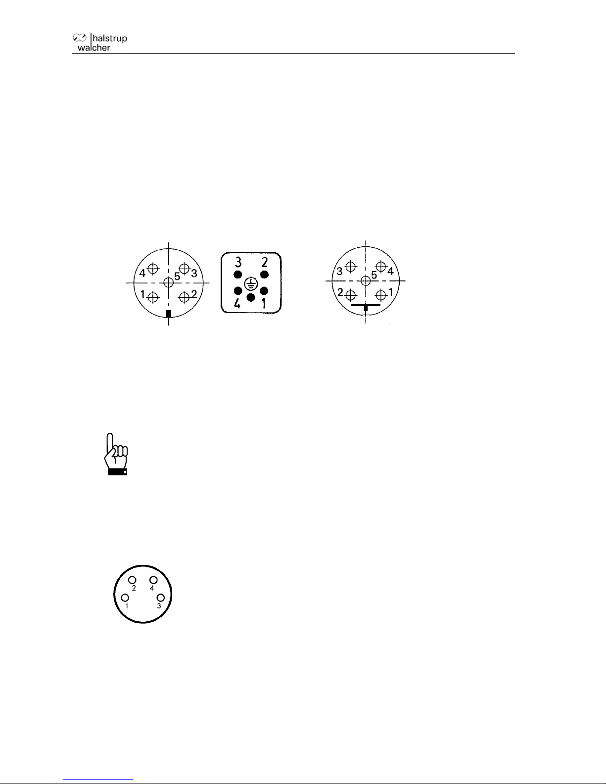
4.3 Pin assignment
For the supply voltage either a Binder series 713/763 (A-coded) round, 5-pin plug for PSE
and PSS devices or a 5-pin Harting plug with protective sleeve (HAN4A) for the PSE34xx
devices is located in the housing cover of the PSx3xxDP.
A series 715 (B-coded) 5-pin round socket and 5-pin plug are provided for connecting the
bus
A Binder series 718 4-pin plug is used to connect the jog keys (optional).
Supply voltage connector: Profibus DP connector (B encoded)
(external top view) (external top view)
Binder 713/763 Harting(PSE34xxDP)
1 +24VDC (final stage) 1 VP +5V
2 ground (final stage) 2 RxD/TxD–N / A cable
3 +24VDC (control unit) 3 DGND (reference potential to VP)
4 ground (control unit) 4 RxD/TxD–P / B line
5 housing/pressure balance 5 shield
To prevent the ingression of fluids into the PSW-housing during
cooldown, use a special cable with an airtube for pressure
balancing of your PSW.
Optional connectors
Connector for external keyboard )
4-pin Binder 718 connector
(External top view)
1
bn
+24V(from control unit)
2
ws
forward key
3
bl
reverse key
4
sw
GND(from control unit)
Electrical grounding
Next to the connecting plugs there is a M4 stud bolt. It is recommended to connect the
positioning system with a cable as short as possible to the machine base. The minimum
wire cross section therefor is 1.5mm².
Page 10
PSx3xxDP Instruction Manual
10
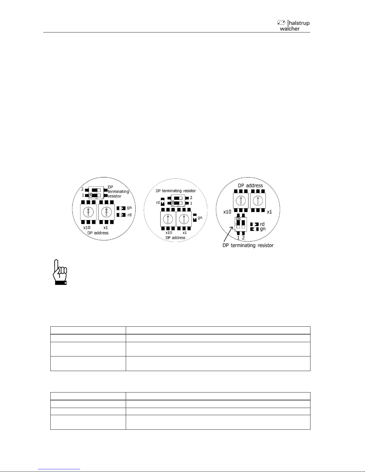
4.4 Setting the device address and terminating resistors
Removing the protective cap provides access to two rotary switches for setting the device
address and a DIP switch to set the terminating resistors.
The rotary switches indicate the tens and ones places of the address selected. A setting
of 01 is the delivery state; the PSx3xxDP identifies itself using address 1 at the bus.
To activate the terminating resistors both switches must be in position ON (If active,
remove the connection to a following device).
Switch configurations:
PSx30xDP,
PSx31xDP-8,
Psx32xDP,
PSx31xxDP
PSx31xDP-14,
PSx33xDP-14
PSx34xxDP
Important: Always replace the protective cap after setting the address. This will
prevent dust and contaminants from entering the housing.
4.5 LED status
The red LED indicates the operating status of the Profibus DP.
LED status
Meaning
LED remains lit
The Profibus DP is not connected or is inactive
LED flashes
The instrument has detected data transfer activity on the bus and
identified the transfer rate.
LED is not lit
Provided the power supply is switched on, an unlit LED indicates
that the instrument is involved in bus communication.
The green LED indicates the status of the power supply.
LED status
Meaning
LED remains lit
Power supply of control unit and motor is activ
LED flashes
Power supply of the motor is inactive.
LED is not lit
Power supply of the control unit is inactive. The status of the
motor supply could not be detected in this case.
Page 11

PSx3xxDP Instruction Manual
11
4.6 Using the bus to set the address
The Profibus DP can also be used to set the device address, provided the address switch is set
to 00. In the delivery state, the instrument will identify itself using address 100. Various devices
(such as the BW1311 Profibus Master Simulator, see link below) can be used to change this
address. The address is then saved and can be used to communicate with the instrument the
next time it is switched on. The address set at the address switches always takes precedence,
i.e., if an address other than 00 has been set at the address switch, this address is always used
for communication with the instrument.
Link to Profibus Master Simulator BW1311:
http://www.bihl-wiedemann.de/en/products/bus-couplersmaster-simulators/productoverview-bus-couplersmaster-simulators/l/bw1131.html
Using the address switch instead of the bus to set the Profibus address
offers numerous advantages and more safety. As such, the bus should
only be used for settings when absolutely necessary.
4.7 Using the parameter module to set the address (firmware version 8)
The parameter module can also be used for setting the device address via the bus if no
bus assistant is available for setting the address.
The instrument is projected using the 100 address. Only the 'parameter' module and the
status byte are required. The following settings are set to the device once bus
communication has been initiated.
Parameter index = 126(0x7E)
Parameter data out = 170(0xAA) The 'hardware error' bit is activated in the
status byte
Parameter index = 52(0x34) index DP address
Parameter data in = 0000 set by the instrument
Parameter data out = new DP address
Parameter index = 180(0xB4) index write DP address
Parameter data in = 0000 set by the instrument
Parameter data out = new DP address
The instrument saves the address and resets, after which communication with the
instrument can only occur via the new DP address.
The device address for all halstrup-walcher Instruments is 100 by default. If you wish to
incorporate an address change into an SPS project and do not want to use 100, the
address can be changed for a projected address. In this event, all instruments to be
incorporated into the project must be preset to this address (ex.: 50). The bus then
accepts the device with this address (ex.: 50) for data transfer, introduces the transfer
driver and resets to the new address. The transfer driver and the driver with the address
change function can then be reinstalled.
Page 12

PSx3xxDP Instruction Manual
12
5 Jog key operation
5.1 Connecting the keyboard
The jog keys attach to the instrument via the 4-pin connector. The switching contacts must be
connected between +24V and the jog key inputs. Both GND cables must be connected if using
an external power supply, making certain that the GND cable for the jog keys is linked to the
control unit GND cable.
5.2 Using the control unit to activate the jog keys
The jog keys are inactive by default. The jog key status is copied into the status byte, giving the
user the ability to activate jog key functions from the control unit. This only works, however, if the
release has been set in the command byte and the ‘accept and proceed to position’ bit has not
been set. Jog key bits can now be copied from the status byte to the command byte, and the
drive may begin a positioning sequence. This also allows operators to use the control unit as a
means of executing a positioning sequence at one drive using the jog keys of another drive.
5.3 Direct positioning using the jog keys
Direct jog key positioning requires that the jog key function be released, either when setting
parameters or by means of the ‘manual run release’ bit in the command byte. The ‘release’ bit
must be set and the ‘accept and proceed to position’ bit must not be activated. Any jog key input
will now be executed directly by the drive.
5.4 Incremental manual operation
When a jog key is depressed, the drive will move by the distance specified in the ‘jog key
increment size’ parameter. The instrument will then wait for the amount of time specified by the
‘jog key pause’ parameter. If the key remains depressed, the drive will resume operation at
manual speed and will continue until either the key is released or a second key is depressed.
This pause was introduced so that users would have sufficient time to release the key in order to
position the drive in individual increments.
5.5 Incremental operation
Setting the ‘jog key pause’ parameter to zero will suppress manual operation, making it possible
to operate the drive solely in increments.
Page 13

PSx3xxDP Instruction Manual
13
6 Start-up
6.1 Setting the reference position
Once it has been installed, the PSx3xxDP must be moved to the reference position, either
via the jog keys or with a positioning command. The ‘set reference position' command
(see section entitled ‘Command byte configuration’) is used to set the internal position of
the PSx3xxDP to zero. This position is saved by the instrument and used as a reference
for all positioning data and ranges.
Position 0000 was assigned to the reference point for firmware version 6 and lower.
Beginning with firmware version 7, however, the reference position is assigned the value
of the module target position. The reference position and assigned position are both
permanently stored in the instrument.
6.2 Positioning sequence
The PSx3xxDP distinguishes between the following steps of a positioning sequence
(It is assumed that all target positions are approached via forward motion.)
1. New position value is larger than the current value: position approached directly.
2. New position value is smaller than the current value: the instrument reverses by the
length of the reference loop and approaches the exact position after resuming forward
motion.
3. New position value after reverse run (no reference loop): the instrument always
approaches the position by moving forward the length of the reference loop; if
necessary, it will first reverse by one rotation.
Once the target position has been reached, the instrument compares it to the internal
absolute encoder status. If a discrepancy is detected, the instrument then sets the
“positioning error” status bit.
The length of the reference loop and the direction can be configured when setting
parameters or by using the parameter module.
6.3 Positioning sequence (without reference loop)
The “positioning without a reference loop” mode is used primarily for moving the small
distances involved in fine adjustments. In this case, each position is approached directly.
This does NOT eliminate any play present in the spindle in question. The PSx3xxDP
internal gear backlash does not play a role in this case, as position data are acquired
directly at the output shaft.
Underwater usage of the PSW is not allowed.
Page 14

PSx3xxDP Instruction Manual
14
7 Interface
Modules
Format
Meaning
status byte
16 bit
flags for instrument status
actual
position
signed long 32 bit
current actual position in target-value increments
command
byte
16 bit
flags for controlling the instrument
target
position
signed long 32 bit
next position to be achieved in target value
increments
parameters
8 bit index
signed int 16 bit data in
signed int 16 bit data out
set and/or read out parameters, indexed
actual
index
8 bit
index of the parameter that has been read out
The status byte provides the user with information on the current status of the PSx3xxDP.
The actual position indicates the current position at which the positioning unit is located.
The command byte is used to transmit commands to the positioning unit.
The target position is used for transmitting the next position to be reached.
During operation, the parameter module allows users to adjust instrument settings directly (via
the control unit) that could otherwise only be modified when setting parameters.
7.1 Status byte configuration
Bit
Hexadec.
Meaning
15(MSB)
0x8000
target position reached
14
0x4000
drive running
13
0x2000
motor supply voltage OK
12
0x1000
ready
11
0x0800
hardware error
10
0x0400
positioning run aborted
9
0x0200
jog key, down
8
0x0100
jog key, up
7
0x0080
temperature too high
6
0x0040
drag error
5
0x0020
invalid target / parameter value
4
0x0010
positioning error
3
0x0008
manual rotation
2
0x0004
no supply voltage available to motor
1
0x0002
positive range limit
0(LSB)
0x0001
negative range limit
7.1.1 Target position reached
The drive is at the target position ± the permissible deviation defined by the positioning window.
7.1.2 Drive running
The drive is performing a positioning run.
Page 15

PSx3xxDP Instruction Manual
15
7.1.3 Motor supply voltage OK
The power supply to the motor is higher than the value indicated in the ‘min. supply voltage’
parameter. This bit must be set prior to performing a run. The level of the supply voltage has a
significant effect on the torque and/or motor speed.
7.1.4 Ready
Supply voltages, temperature and target position are all in the permissible range and the drive
can begin operation. An exception here is when the display indicates a hardware error, which the
operator must acknowledge (thereby deleting the error message) before performing the run.
7.1.5 Hardware error
This bit is set if an error is detected during an internal process and causes the drive to stop. The
‘error status’ parameter can be used to determine the source of the error. This bit can be deleted
by temporarily deactivating the release bit in the command byte, an action that causes the error
to be recorded in an internal error memory. The ‘save’ command can be used to save this error
memory in the instrument’s non-volatile EEPROM.
7.1.6 Positioning run aborted
The positioning run has been aborted, either because the release bit was reset or because of an
error.
7.1.7 Jog key, down
This bit indicates that the ‘down’ jog key has been depressed. A manual run can be performed
directly either if the ‘manual run release’ bit in the command byte has been activated or if the
manual run was released when setting parameters and the positioning bit has not been set.
7.1.8 Jog key, up
This bit indicates that the ‘up jog key’ input has been activated (connected to +24V). A manual
run can be performed directly either if the ‘manual run release’ bit in the command byte has been
activated or if the manual run was released when setting parameters and the positioning bit has
not been set.
7.1.9 Temperature too high
The PSx3xxDP positioning unit is equipped with a simple temperature monitoring device
intended to avoid a thermal overload. This bit is set if the temperature inside the instrument
exceeds the temperature limit set in the parameters; new positioning runs can only be performed
once the instrument has cooled down (the 'temperature too high' bit is reset). The 'temperature
too high' bit must be reset with the confirmation bit.
Page 16

PSx3xxDP Instruction Manual
16
7.1.10 Drag error
If the load moment prevents the drive from achieving the target rpm, the current position will not
agree with that for the target rpm, a situation that can cause problems when multiple drives are
running in parallel. The ‘drag error’ parameter allows the user to establish the maximum
discrepancy. This bit is activated if the difference exceeds that of the set value; the run is not
interrupted. The action required to eliminate this problem must be monitored by the external
control unit.
7.1.11 Invalid target/parameter value
The operator has attempted to enter a target value or a parameter that lies outside of the valid
range.
7.1.12 Positioning error
After the positioning run, the difference between the actual and target values is larger than the
positioning window. The bit is deleted during the subsequent positioning run.
7.1.13 Manual rotation
Following a positioning run, an external load moment was applied to the drive, rotating it out of its
final position.
7.1.14 No supply voltage available to motor
The power supply to the motor fell below a value of roughly 17 V. Deleting this bit requires a 10
transition for the confirmation bit in the command byte.
7.1.15 Upper range limit
The drive has exceeded the upper limit of the user-defined positioning range and can no longer
move in the positive direction. This bit is deleted as soon as the drive is within the permissible
range. If the drive is switched off in this position, the instrument may produce positioning errors
when switched back on.
7.1.16 Lower range limit
The drive has exceeded the lower limit of the user-defined positioning range and can no longer
move in the negative direction. This bit is deleted as soon as the drive is within the permissible
range. If the drive is switched off in this position, the instrument may produce positioning errors
when switched back on.
7.2 Actual position
In this modul the drive is sending current actual position in target-value increments
Page 17

PSx3xxDP Instruction Manual
17
7.3 Control byte configuration
7.3.1 Confirmation
When this bit undergoes a 10 transition, all hardware errors and the error status are transferred
to the error memory and deleted. The save command can be used to transfer the error memory
to the internal EEPROM memory (performed automatically in firmware version 7 and up once the
error is confirmed). Having the error memory analyzed by the manufacturer can be extremely
helpful when performing an error search.
7.3.2 Release bit
If this bit is set, the drive can run. If it is deleted during a run, the drive will stop.
7.3.3 Manual run release
If this bit is set and the ‘accept and proceed to position’ bit is not set, status information from the
external jog keys will be used to control the positioning unit directly.
7.3.4 Run with no reference loop
If this bit is set, the reference loop can be suppressed, even if it has been activated during the
parameter setting process.
7.3.5 Set value for reference position
The drive can be assigned a reference position (‘set and save reference position’) when it is
mounted. This reference position, which serves as the new zero position for the drive, is saved in
the instrument and can be assigned a new numerical value via the control unit. The new
numerical value is written into the target position module and this bit is then activated briefly. In
order to prevent an unwanted run, no other bit can be set in the command byte; otherwise the
value will not be accepted.
For firmware version 7 and higher, this value should be transferred when setting the reference
position for the target position, as it can now be saved permanently.
Bit
Meaning
15(MSB)
not assigned
14
not assigned
13
not assigned
12
not assigned
11
not assigned
10
not assigned
9
not assigned
8
confirmation for hardware error
7
release bit
6
manual run release
5
run with no reference loop
4
set value for reference position
3
set and save reference position
2
accept and proceed to position
1
manual run, down
0(LSB)
manual run, up
Page 18

PSx3xxDP Instruction Manual
18
7.3.6 Set and save reference position
If this bit has been activated and the remaining bits in the command byte have not been set, the
current position will be saved as the instrument’s new zero position. All positional data now use
this point as a reference. In order to prevent and unwanted run, no other bit can be set in the
command byte; otherwise the value will not be accepted.
For firmware version 7 and higher (parameter software: 15507), the current position transferred
in the target position module is assigned to the reference point and saved permanently.
Example: Set reference point, target position = 1000 new actual position = 1000.
7.3.7 Accept and proceed to position
This bit signals the positioning unit that a valid target value has been provided. The drive will
begin a new positioning run as soon as this bit is set (provided the release bit has been set). For
this to occur, the release bit must be set and no errors may be active.
7.3.8 Manual run, down
A manual run is started if this bit is set and the ‘accept position’ bit has not been set. The run
begins with a single increment, the length of which can be set via the ‘jog key increment size’
parameter. The drive then waits the amount of time specified by the ‘jog key pause’ parameter;
afterwards the run continues at the speed set in the ‘manual run’ parameter until the operator
disengages the key. A manual run will not be performed if the pause is set to 0 ms, in which case
the run can only proceed in single increments.
7.3.9 Manual run, up
See 7.2.8 Manual run, down
7.4 Target position
This 32Bit Value will send the next position to be achieved in target value increments to the drive.
When activating the ‘accept and proceed to position’ bit in the control word the drive will start to
move towards this position. If the bit reamins set, the drive will follow each change of this value
immediately.
7.5 Parameters
Index
Meaning
Default
Range of values
Access
0
direction of rotation
+1
-1 = left
+1 = right
R
1
direction of travel
0
-1 = left
0 = none
+1 = right
R/W
2
position correction
0
0 = off; 1 = on
R/W
3
jog key operation
0
0 = off; 1 = on
R/W
4
hardware resolution
1024
1 … 1024
R/W
5
software resolution (0.01 mm/rev.)
400
1 … 1024
R/W
6
positioning window
min
1 … 100 [1/1024 revolutions]
R/W
7
max. run distance, positive
9880
-100.00% … 100.00% [0.01%]
R/W
8
max. run distance, negative
-40
-100.00% … 100.00% [0.01%]
R/W
9
target rpm, positioning run
1000
1 … 120.0% [0. 1%]
R/W
Page 19

PSx3xxDP Instruction Manual
19
Index
Meaning
Range of values
Access
10
target rpm, manual run
100
1 … 120.0% [0. 1%]
R/W
11
max. rpm, left
1200
1 … 120.0% [0. 1%]
R/W
12
max. rpm, right
1200
1 … 120.0% [0. 1%]
R/W
13
max. torque
1000
1 … 100.0% [0. 1%]
R/W
14
max. torque, left
1000
1 … 100.0% [0. 1%]
R/W
15
max. torque, right
1000
1 … 100.0% [0. 1%]
R/W
16
max. starting torque
1000
1 … 125.0% [0. 1%]
R/W
17
duration of starting torque
100
1 … 1000 [ms]
R/W
18
holding torque
500
1 … 100.0% [0. 1%]
R/W
19
drag error
100
20 … 2000 [0.01mm]
R/W
20
Min. rpm for detecting an obstacle
10
1 .. 60% [1%]
R/W
21
time required to detect an obstacle
100
1 … 500 ms
R/W
22
wait time between runs
50
20 … 10000 ms
R/W
23
min. supply voltage
190
15.0 … 24.0 V
R/W
24
filter value for voltage monitoring
100
100 … 1000 [1ms]
R/W
25
loop length
100
0 … 1000 [1/1024 revolutions]
R/W
26
jog key increment size
10
1 … 1000 [0.01mm]
R/W
27
jog key pause
500
0 … 1000 [ms]
R/W
28
factor for ramp length
1000
1000…5000 [1/1000]
R/W
29
limiting temperature
70
50 … 100 [°C]
R/W
30
LSW reference position (lower 16 bit)
0
+/- 1000000 [0.01mm]
R/W
31
MSW reference position (upper 16 bit)
0 R/W
32
production date
WWYY
R
33
serial number
0 … 30000
R
34
device type
3xx,312,315
R
35
software version
155xx, xx = software design
specification
R
36
hardware version
0 … 999
R
37
device temperature
0 … 100 [°C]
R
38
actual rpm
rpm
R
39
max. actual torque (current)
0 … 200.0 % [0. 1%]
R
40
run time LSW
[ms] R 41
run time MSW
[ms]
R
42
drag position
R
43
power supply to motor
[0.1V]
R
44
motor current
[mA]
R
45
supply voltage for control unit
[0.1V]
R
46
error code
R
default
drive model
R
These parameters can be set and/or read out via the parameter module (read-only parameters
are those for which access is designated as ‘R’). All parameters are transferred as 16-bit integer
values.
7.5.1 Direction of rotation
This parameter specifies the direction in which the drive rotates. A value of +1 means that the
drive will rotate clockwise (with respect to the output shaft) when increasing the position, whereas
a -1 causes the drive to rotate counterclockwise under the same conditions.
Page 20

PSx3xxDP Instruction Manual
20
7.5.2 Direction of travel
If the length of the reference loop has been defined, this parameter establishes the direction in
which the drive will approach the target position. If the direction of travel = 0, each position will be
approached without a reference loop. A value of +1 indicates movement to the right (clockwise)
and -1 indicates movement to the left. A reference loop is automatically inserted whenever a
position has been approached from a different direction.
7.5.3 Position correction
If, after a correctly executed positioning run, the drive is forcibly moved out of position in the
opposite direction, the drive will attempt to correct the position provided this parameter is set to 1.
A value of 0 switches this function off. Using devices with an optional holding brake this
parameter must be set to 0.
7.5.4 Jog key operation
This parameter can be used to determine whether jog key commands are sent directly to the
drive. If this parameter is set to 1 and the ‘accept and proceed to position’ bit is not set, then drive
will execute all commands entered via the jog keys. If this parameter is set to zero, jog key
commands are merely signaled in the status byte. The user can then either perform a manual run
using the bits in the command byte or redirect this action to a different drive.
7.5.5 Hardware resolution
This parameter specifies the internal resolution of the drive and is involved in the process of
translating external positions into an internal position. If this parameter remains at 1024, the
following parameter can be used to set the drive resolution per rotation. (400 corresponds to 400
increments per rotation or 0.01 mm/ increment at a spindle pitch of 4.0 mm.) Changing this
parameter will interrupt any positioning run that is underway and may result in positioning errors.
7.5.6 Software resolution
This parameter, along with the preceding parameter, specifies the drive resolution per rotation
when transmitting the position via the Profibus.
resolutionhardware
resolutionsoftware
rotation
increments
_
_*1024
The most practical approach is to leave the hardware resolution set to 1024 and then set the
increments/rotation by adjusting the software resolution. Changing this parameter will interrupt
any positioning run that is underway and may result in positioning errors.
7.5.7 Positioning window
If the discrepancy between the actual and target positions is larger than the value specified in the
‘positioning window’ parameter, the ‘target position reached’ bit will not be activated.
Values should be entered in 1/1024 rotations.
Page 21

PSx3xxDP Instruction Manual
21
7.5.8 Max. run distance, positive
This parameter is used for setting the maximum run distance for positive rotation. Values should
be entered as a % of the absolute run distance (256 rotations). The instrument checks to make
certain that the sum of the maximum positive run distance and maximum negative run distance
does not exceed 99.2%; if this is not the case, the value entered will be reduced by the
appropriate amount.
7.5.9 Max. run distance, negative
This parameter is used for setting the maximum run distance for negative rotation. Values should
be entered as a % of the absolute run distance (256 rotations). The instrument checks to make
certain that the sum of the maximum positive run distance and maximum negative run distance
does not exceed 99.2%; if this is not the case, the value entered will be reduced by the
appropriate amount.
7.5.10 Target rpm, positioning run
This parameter stipulates the target rpm for a positioning sequence. The percentage value is
based on the nominal rated speed of the drive in question.
7.5.11 Target rpm, manual run
This parameter stipulates the target rpm for a manual run. The percentage value is based on the
nominal rated speed of the drive in question.
7.5.12 Max. rpm, left
This parameter allows the user to set the maximum rpm for positioning sequences in which the
drive is rotating counterclockwise.
7.5.13 Max. rpm, right
This parameter allows the user to set the maximum rpm for positioning sequences in which the
drive is rotating clockwise.
7.5.14 Max. torque
This parameter allows the user to set the maximum torque for positioning sequences. Torque is
limited by limiting the current to the motor. Values should be entered as a percentage of the
nominal torque.
7.5.15 Max. torque, left
This parameter allows the user to set the maximum torque for positioning sequences in which the
drive is rotating counterclockwise.
7.5.16 Max. torque, right
This parameter allows the user to set the maximum torque for positioning sequences in which the
drive is rotating clockwise.
7.5.17 Max. starting torque
This parameter allows the user to set the maximum torque for the start of a positioning sequence,
thus making it possible to overcome a large breakaway torque if necessary. The following
parameter allows the user to set the duration of this starting torque.
7.5.18 Duration of starting torque
This parameter can be used to stipulate how long the elevated starting torque is to remain active.
Page 22

PSx3xxDP Instruction Manual
22
7.5.19 Holding torque
For many applications, the drive requires a level of holding torque greater than the very low self-
holding torque generated by the drive’s EC motor. This parameter allows the user to set that
holding torque value.
Current is then supplied to one of the motor windings when the drive is not operating. The level of
holding torque should be entered as a percentage of the nominal torque. The smallest possible
level of torque should be selected in order to prevent the drive from heating up unnecessarily,
which would reduce the OT.
7.5.20 Drag error
Because the load profile changes over the course of a positioning run, it sometimes happens that
the drive fails to reach its target rpm. This can lead to problems for applications involving the
synchronous operation of two drives. The ‘drag error’ bit will be set in the status byte if, over the
course of the run, the drive falls short of its theoretical position (target rpm * run time) by more
than the distance specified by the ‘drag error’ parameter. The control unit can then often take
steps to correct the situation. If relatively short distances are involved, the drive itself will attempt
to compensate for the discrepancy by raising its speed by a small amount (+/- 1 rpm). This
corrective function can be deactivated by setting the drag error distance to zero.
7.5.21 Min. rpm for detecting an obstacle
The drive registers an obstacle if the actual rpm = 0 or if the drive speed falls below a certain
percentage of the target rpm for a specific amount of time. This parameter allows the user to set
that percentage value. If the instrument detects an obstacle, the current positioning run will be
aborted and the ‘positioning error’ and ‘positioning run aborted’ bits are set in the status byte.
7.5.22 Time required to detect an obstacle
This parameter specifies how long the drive speed must be less than the minimum rpm described
above before the instrument registers an obstacle.
7.5.23 Wait time between runs
The parameter specifies the minimum amount of time (in ms) that the drive will pause before
reversing its course.
7.5.24 Min. supply voltage
This parameter indicates the voltage at which the ‘motor supply voltage’ bit in the status byte is
activated. No positioning runs can be executed if this bit is not activated. When setting the
voltage level, it is important to consider that, due to a number of different components, the power
supply to the motor is lower than the voltage applied externally. The positioning sequence will not
be aborted if the power supply falls below the required voltage by only a small amount during a
run.
7.5.25 Filter value for voltage monitoring
This parameter allows operators to bridge brief voltage dips, such as may occur as a result of the
initial current. The ‘motor supply voltage OK’ bit is only set when the voltage dip lasts longer than
the amount of time specified in this parameter.
Page 23

PSx3xxDP Instruction Manual
23
7.5.26 Loop length
The ‘direction of travel’ parameter can be used to instruct the drive to approach all positions from
the same direction. If a positioning run is performed in the opposite direction, the drive will first
move past its target and then perform a second positioning sequence, which takes it to the
desired target position. This parameter allows the user to specify the length of this loop (value
should be entered in hardware increments).
7.5.27 Jog key increment size
Briefly depressing the jog keys causes the drive to move a defined distance in a given direction.
This parameter allows the user to specify this distance (value should be entered in software
increments).
7.5.28 Jog key pause
Briefly depressing a jog key causes the drive to move a defined distance, after which it will wait
for the amount of time specified by this parameter and then start again in the corresponding
direction at the speed indicated in the ‘target rpm, manual run’ parameter. Manual operation is
suppressed if the jog key pause is set to zero, allowing the jog keys to function only in
increments.
7.5.29 Factor for ramp length
This parameter allows the user to influence the length of the deceleration ramp for applications in
which large moments of inertia need to be overcome.
The value should be entered as an integer, where 1000 corresponds to a factor of 1.0 and 800
corresponds to a value of 0.8, i.e., a shorter ramp. Positioning times will be decreased if the ramp
is reduced; the risk of positioning errors increase, however.
7.5.30 Limiting temperature
The drive is equipped with a temperature sensor. If the measured temperature exceeds the
temperature limit specified by this parameter, the ‘temperature exceeded’ bit in the status byte is
activated and the drive stops. No new runs may be performed until the drive temperature has
returned to below the temperature limit.
7.5.31 Reference position MSW
This parameter can be used to read out and/or set the upper 16 bits of the reference position
value. The reference position is the position value that the drive displays when it reaches the
point corresponding to its assigned reference position (internal zero point).
7.5.32 Reference position LSW
This parameter can be used to read out and/or set the upper 16 bits of the reference position
value. The reference position is the position value that the drive displays when it reaches the
point corresponding to its assigned reference position (internal zero point).
7.5.33 Production date
This parameter is available only for read-out. The manufacturer has saved the production date
plus the year and day of manufacture in this parameter as an aid in documenting the technical
status of the instrument.
7.5.34 Serial number
The serial number is stored in this parameter as an aid in documenting the technical status of the
instrument.
Page 24

PSx3xxDP Instruction Manual
24
7.5.35 Device type
The device model is stored here as a hexidecimal figure.
Format: xxxy (xxx = design and torque, y = diameter of the output shaft $E = 14 mm, 8 = 8 mm).
7.5.36 Software version
This parameter contains the version number for the firmware stored on the instrument. The
output value is given as a decimal 155xx(xx = firmware design specification).
7.5.37 Hardware version
This parameter contains the design specification number for the instrument.
7.5.38 Device temperature
This parameter can be used for querying the current temperature measured inside the instrument
(in °C).
7.5.39 Actual rpm
This parameter can be used for querying the current drive speed (output in rpm) while a
positioning run is still in progress. Values should be entered in rpm.
7.5.40 Max. actual torque (current)
Torque is monitored throughout a positioning sequence from the end of the initial torque period
until the current is slowed. The highest value measured here is used to calculate maximum
torque. This parameter can be used to monitor the mechanical equipment in that the value will
increase when motion becomes difficult. This increase would then serve as a reason for
inspecting the equipment.
7.5.41 Run time MSW
This parameter reads out the upper 16 bits of the run time (in ms) for the most recent positioning
sequence.
7.5.42 Run time LSW
This parameter reads out the lower16 bits of the run time (in ms) for the most recent positioning
sequence.
7.5.43 Drag position
This parameter reads out the difference between the current and theoretical actual positions
(target rpm * time).
7.5.44 Motor supply voltage
This parameter reads out the motor supply voltage (measured internally) in 0.1V increments.
While the measured value can then serve as an indicator, the measurement precision, however,
is very poor (ca. +/-1V).
7.5.45 Motor current
This parameter reads out the present motor current in mA.
7.5.46 Supply voltage for control unit
This parameter can be used for reading out the supply voltage to the drive control unit.
Resolution: 0.1V; precision: approx. +/- 1V.
Page 25

PSx3xxDP Instruction Manual
25
7.5.47 Error code
This byte is used as a more precise diagnostic tool for troubleshooting a number of different
errors, especially hardware errors. The meanings of individual bits are shown in the following
table:
Bit
Hexadec.
Meaning
15(MSB)
0x8000
learn mode active (for manufacturer’s use only)
14
0x4000
for internal use
13
0x2000
temperature too high
12
0x1000
error in motor memory
11
0x0800
error in DP address memory
10
0x0400
device parameters have been reset
9
0x0200
supply voltage to motor was less than 16V
8
0x0100
saved parameters incorrect
7
0x0080
Profibus chip is registering an error
6
0x0040
Profibus communication disrupted
5
0x0020
release was reset during a run
4
0x0010
invalid target position = outside of positioning range
3
0x0008
invalid parameter values
2
0x0004
encoder error
1
0x0002
supply voltage to motor is too low
0(LSB)
0x0001
actual position lies outside of positioning range
A few of these errors prevent the drive from performing any further runs, in which case the error
code byte must be reset. This is accomplished by resetting the release in the command byte, an
action that also saves the most recent error code in the internal EEPROM, where the
manufacturer can access it at a later date for determining the mechanism, if necessary, by which
a given error occurred.
7.6 Changing parameter values
Change parameter values by first using the index to select the parameter in question. The current
value is reported in the 'Data In' module. The 'Current Index' module returns the set index as an
echo signal and the new value is written in the 'Data Out' module. The instrument then checks
the plausibility of the new value and, if it detects an error, sets the 'invalid target and/or
parameter value' bit in the status byte. If it does not set this bit, the MSB(0x80) in the index byte
can be set in order to transmit the value to the instrument. If the value is accepted, it is then in
read out in the 'Data In' module. The MSB(0x80) in the index byte must now be reset to prevent
any accidental writing processes when changing the index byte.
Page 26

PSx3xxDP Instruction Manual
26
8 Backing up parameter data and the error memory
A special command allows the user to store parameter data in the EEPROM area, a process
which does not affect the functioning of the instrument for the user. Every time the Profibus DP
starts up, parameter data are reloaded through the bus, making saved data are irrelevant. What
is important, however, is saving data when hardware errors crop up during operation. In this
case, this procedure can be used to transfer the contents of the error memory to the EEPROM.
Parameter index = 0x7D (dec 125)
Parameter data = 0x55 (dec 85)
This back-up procedure takes less than 1 s, after which the drive must register the value ‘0000’
as parameter data.
Important: Do not turn off the instrument while backing up data, as this could cause
important parameter data to be deleted.
Page 27

PSx3xxDP Instruction Manual
27
9 Technical data
9.1 Drive speed and torque
drive model
PSE and PSS
301_8
301_14
311_8
311_14
302_8
302_14
312_8
312_14
305_8
305_14
315_8
322_14
332_14
325_14
335_14
nominal output torque (30 % OT)
1 Nm
2 Nm
5 Nm
2 Nm
5 Nm
temporary breakaway torque
~ 1.25 Nm
~ 2.5 Nm
~ 6.25 Nm
~ 2.5 Nm
~ 6.25 Nm
self-holding torque (w/ current)
~ 0.5 Nm
~ 1 Nm
~ 2.5 Nm
~ 1 Nm
~ 2.5 Nm
nominal output speed
230 rpm
100 rpm
40 rpm
150 rpm
68 rpm
drive model
PSE and PSS
338-14
3210-14
3218-14
3310-14
3325-14
nominal output torque (30 % OT)
7 Nm
10 Nm
18 Nm
10 Nm
25 Nm
temporary breakaway torque
~ 8 Nm
~ 12,5 Nm
~ 22,5 Nm
~ 12.5 Nm
~ 27,5 Nm
self-holding torque (w/ current)
~ 3 Nm
~ 5 Nm
~ 9 Nm
~ 5 Nm
~ 12.5 Nm
nominal output speed
45 rpm
30 rpm
17 rpm
25 rpm
10 rpm
drive model
PSW
301_8
301_14
311_8
311_14
302_8
302_14
312_8
312_14
305_8
305_14
315_8
322_14
332_14
325_14
335_14
nominal output torque (30 % OT)
1 Nm
2 Nm
5 Nm
2 Nm
5 Nm
temporary breakaway torque
~ 1.25 Nm
~ 2.5 Nm
~ 6.25 Nm
~ 2.5 Nm
~ 6.25 Nm
self-holding torque (w/ current)
~ 0.5 Nm
~ 1 Nm
~ 2.5 Nm
~ 1 Nm
~ 2.5 Nm
nominal output speed
180 rpm
90 rpm
35 rpm
125 rpm
50 rpm
Page 28

PSx3xxDP Instruction Manual
28
9.2 Drive speed and torque PSE34xx
drive model
PSE3410
PSE3418
PSE3430
nominal output torque (30 % OT)
10 Nm
18 Nm
30 Nm
temporary breakaway torque
ca.12,5Nm
ca.22,5Nm
ca.37,5Nm
self-holding torque (w/ current)
5 Nm
ca. 9 Nm
ca.15 Nm
positioning range
256 rotations
256 rotations
85 rotations
nominal output speed
80 rpm
60 rpm
30 rpm
Page 29

PSx3xxDP Instruction Manual
29
9.3 Ambient conditions
ambient temperature
0 °C to +45 °C
storage temperature
-10 °C to +70 °C
shock resistance according to
DIN IEC 68-2-27
50 g 11 ms
resistance to vibration
according to DIN IEC 68-2-6
10 Hz to 55 Hz 1.5 mm
55 Hz to 1000 Hz 10 g
10 Hz to 2000 Hz 5 g
EMC standards
CE
conformity
CE declaration of conformity available upon request
protection class
PSE
IP 54
PSS
IP 65
PSW
IP 66 (in operation)
IP 68 (at standstill)
duty cycle
Device model
Duty cycle in %
Base time in sec.
PSE34xx
PSE30xx to 33xx
PSS
PSW
20
30
20
20
300
300
600
600
9.4 Electrical data
nominal power output
PSx30xDP, PSx31xDP,
PSE31xxDP
25 W with 30 % duty cycle
PSx32xDP, PSx33xDP
35 W with 30 % duty cycle
PSx34xxDP
100 W with 20 % duty cycle
supply voltage
24 VDC ±10 % (supply voltages for motor and control
unit are galvanically isolated)
advice: use regulated power supplys
nominal current, control unit
0.15 A
nominal current, motor
PSx30xDP, PSx31xDP,
PSE31xxDP
2.2 A
PSx32xDP, PSx33xDP
3.0 A
PSE34xxDP
7.8 A
positioning resolution
0.9°
positioning accuracy
0.9°
Profibus DP
addresses set via decade switches 0…99
9.6, 19.2, 45.45,
93.75,187.5,500,1500,3000,6000,12000 kBaud
absolute value acquisition
optical - magnetic
Page 30

PSx3xxDP Instruction Manual
30
9.5 Physical data
positioning range
250 usable rotations, no mechanical limits
measuring system has a span of 256 turns, minus 3
turns security stock at upper and lower range limit
torsional rigidity
(angle of rotation when switching
from operation without backlash to
maximum torque)
max. 0.2°
gear backlash
(without spindle compensation run)
max. 0.5°
spindle lash compensation
automatic loop after every positioning run (may be
deactivated)
output shaft
PSE30xDP-8
PSE31xDP-8
8H9 hollow shaft with
adjustable collar
PSE30xDP-14,
PSE31xDP-14, PSE32xDP,
PSE33xDP
14H7 hollow shaft with
adjustable collar
PSE338DP
PSE31xxDP
PSE32xxDP
PSE33xxDP
PSE34xxDP
14H7 hollow shaft with
clamp and feather key
PSS3xxDP-8
PSW3xxDP-8
8H9 hollow shaft with adj.
collar or
8h8 solid shaft
PSS3xxDP-14
PSW3xxDP-14
14H7 hollow shaft with
adj. collar or
14h8 solid shaft
recommended diameter of the
spindle head
according to the hollow shaft diameter with an
interference fit of h9
maximum radial force
40 N
maximum axial force
20 N
dimensions (l x w x h)
see catalog data on our website
weight (approx.)
PSx30xDP-8
650 g
PSx30xDP-14, PSx32xDP
1200 g
PSx31xDP-8
700 g
PSx31xDP-14, PSx33xDP
700 g
PSE31xxDP
1200 g
PSE34xxDP
1900 g
For additional specifications and dimension drawings, please visit our website at
http://www.halstrup-
walcher.de/en/produkte/positioniertechnik/positioniersysteme/index.php
7100.003964G_PSx3xxDP.doc 03/2017 Si
Page 31

PSx3xxDP Instruction Manual
31
 Loading...