

Page 1
Instruction Manual
PSx3xxDN
halstrup-walcher GmbH
Stegener Straße 10
D-79199 Kirchzarten, Germany
Phone: +49 (0) 76 61/39 63-0
Fax: +49 (0) 76 61/39 63-99
E-mail: info@halstrup-walcher.com
Internet: www.halstrup-walcher.com
Document 7100.004144 03/2017
Page 2

PSx3xxDN Instruction Manual
2
Table of Contents
1 Safety precautions ............................................................................................................ 4
1.1 Appropriate use .............................................................................................................. 4
1.2 Shipping, assembly, electrical connections and start-up................................................. 4
1.3 Troubleshooting, maintenance, repairs, disposal............................................................ 4
1.4 Symbols ................................................................................................ ......................... 5
2 Device description ......................................................................................................... 5
2.1 Features ..................................................................................................................... 5
2.2 Installation .................................................................................................................. 5
2.3 Pin assignment........................................................................................................... 6
2.4 Setting the device address and baud rate .................................................................. 7
2.5 Start-up ...................................................................................................................... 9
2.6 CAN Bus .................................................................................................................... 9
3 Sequence of positioning steps ........................................................................................ 26
4 Special features .............................................................................................................. 27
5 Technical data ................................................................................................................. 33
Page 3

PSx3xxDN Instruction Manual
3
Purpose of instruction manual
This instruction manual describes the features of PSx3xxDN positioning systems and
provides guidelines for their use.
Improper use of these devices or failure to follow these instructions may cause injury
or equipment damage. All individuals responsible for operating these devices must
therefore be properly trained and aware of the hazards. The instruction manual, and
in particular the safety precautions contained therein, must be followed carefully.
Contact the manufacturer if you do not understand any part of this instruction
manual.
Handle this manual with care:
It must be readily available throughout the lifecycle of the devices.
It must be provided to any individuals who assume responsibility for operating the
device at a later date.
It must include any supplementary materials provided by the manufacturer.
The manufacturer reserves the right to continue developing this device model without
documenting such development in each individual case. The manufacturer will be
happy to determine whether this manual is up-to-date.
Conformity
This device corresponds to the state of the art and meets all legal requirements set
forth in EC directives as evidenced by the CE label.
© 2010, 2015, 2016, 2017
The manufacturer owns the copyright to this instruction manual. This manual contains
data, instructions and drawings pertaining to the features and usage of these devices;
copying this manual in part or in full or distributing it to third parties is prohibited.
Page 4

PSx3xxDN Instruction Manual
4
1 Safety precautions
1.1 Appropriate use
Positioning systems are especially suitable for automatically setting tools, stops or
spindles for wood-processing equipment, packing lines, printing equipment, filling
units and other types of special machines.
PSx3xxDN positioning systems are not stand-alone devices and may only be
used if coupled to another machine.
Always observe the operating requirements—particularly the permissible supply
voltage—indicated on the rating plate and in the “Technical data” section of this
manual.
The device may only be handled as indicated in this manual. Modifications to the
device are prohibited. The manufacturer is not liable for damages caused by improper
use or failure to follow these instructions. Violations of this type render all warranty
claims null and void.
1.2 Shipping, assembly, electrical connections and start-up
Only technical personnel who are appropriately trained and authorized by the
operator of the facility may assemble the device and set up its electrical connections.
The device may only be operated by appropriately trained individuals who have been
authorized by the operator of the facility.
Specific safety precautions are given in individual sections of this manual.
1.3 Troubleshooting, maintenance, repairs, disposal
The individual responsible for the electrical connections must be notified immediately
if the device is damaged or if errors occur.
This individual must take the device out of service until the error has been corrected
and ensure that it cannot be used unintentionally.
This device requires no maintenance.
Only the manufacturer may perform repairs that require the housing to be opened.
The electronic components of the device contain environmentally hazardous
materials and materials that can be reused. For this reason the device must be
recycled in accordance with the environmental guidelines of the jurisdiction in
question once it has been taken permanently out of service.
Page 5

PSx3xxDN Instruction Manual
5
1.4 Symbols
The symbols given below are used throughout this manual to indicate instances when
improper operation could result in the following hazards:
WARNING! This warns you of a potential hazard that could lead to bodily injury up
to and including death if the corresponding instructions are not followed.
WARNING: This warns you of a potential hazard that could lead to significant
property damage if corresponding instructions are not followed.
INFORMATION: This indicates that the corresponding information is important
for operating the device properly
2 Device description
2.1 Features
The PSx3xxDN positioning system, an intelligent, compact, complete solution for
positioning auxiliary and positioning axes, consists of an EC motor, gear power
amplifier, control electronics, absolute measuring system and DeviceNet interface.
The integrated absolute measuring system eliminates the need for a time-consuming
reference run. Connecting to a bus system simplifies the wiring. A hollow shaft with
adjustable collar makes assembly quite simple. The positioning system is especially
suitable for automatically setting tools, stops or spindles for wood-processing
equipment, packing lines, printing equipment, filling units and other types of special
machines.
PSx3xxDN positioning systems convert a digital positioning signal into an angle of
rotation.
2.2 Installation
Hollow shaft:
The PSx3xxDN is mounted onto the machine by sliding the hollow shaft of the
positioning gear onto the axis to be driven and then securing it with an adjustable
collar (recommended diameter of the axis is either 8h9 or 14h9; wrench torque for
screw: 1.5Nm). The adjustable collar should be tightened only just to the point where
it can no longer rotate freely.
Securing the pin under the hollow shaft into an appropriate bore will prevent further
rotation.\line (see drawing)
Page 6
PSx3xxDN Instruction Manual
6
Solid shaft:
The PSx3xxDN is mounted on the machine by fixing the solid shaft with coupling and
intermediate flange to the axis of the machine.
Never apply force to the housing cover, e.g., for supporting weight.
Driving the PSx3xxDN rearward is prohibited (e.g. it’s not allowed to turn
the output shaft by an external force).
2.3 Pin assignment
For the supply voltage either a Binder series 715 (B-coded) round, 5-pin plug for PSE
and PSS devices or a 5-pin Harting plug with protective sleeve (HAN4A) for the
PSE34xx devices is located in the housing cover of the PSx3xxDN.
A series 713 (A coded) 5-pin round socket and 5-pin plug are provided for connecting
the CAN bus.
A Binder series 718 4-pin plug is used to connect the jog keys (optional).
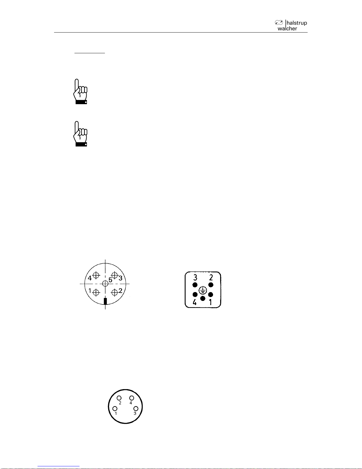
Connector for supply to motor:
Round plug Harting plug
(external top view)
1 +24V motor
2 GND motor
3 not assigned
4 not assigned
5 housing/air drill
Connector for jog keys:
(external top view)
1 +24V (output)
2 forward key
3 reverse key
4 ground
Page 7
PSx3xxDN Instruction Manual
7
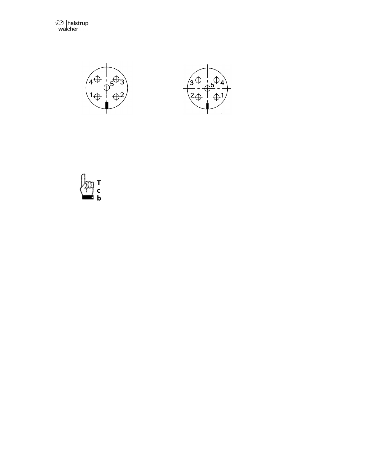
Round plug for CAN bus: Round socket for CAN bus:
(external top view) (external top view)
1 shield
2 +24V control module
3 GND
4 CAN_H
5 CAN_L
To prevent the ingression of fluids into the PSW-housing during
cooldown, use a special cable with an airtube for pressure
balancing of your PSW.
Electrical grounding
Next to the connecting plugs there is a M4 stud bolt. It is recommended to connect
the positioning system with a cable as short as possible to the machine base. The
minimum wire cross section therefor is 1.5mm².
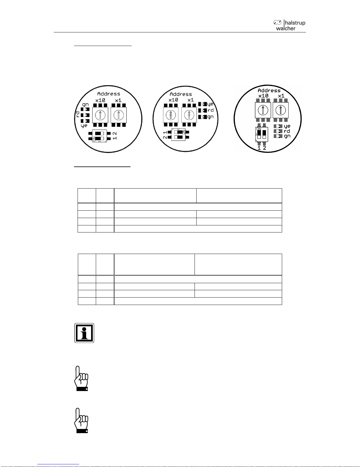
2.4 Setting the device address and baud rate
Removing the protective cap provides access to two rotary switches for setting the
device address at the bus and a 2-pin sliding switch for setting the baud rate.
The rotary switches indicate the tens and ones places of the address selected. If the
switches are resting in positions between 64 and 99, the address is set using
DeviceNet (PSE object; class 100, instance 1, attribute 38; starting from software
version 147).
The delivery setting is 99, the PSx3xxDN reports to the bus with the address 63.
If the switches have been used to set the address (i.e. the switch setting is < 64), this
value cannot be changed via DeviceNet.
The yellow LED represents the state of the motor supply voltage, the red and green
LEDs represent the DeviceNet state.
Page 8
PSx3xxDN Instruction Manual
8
Switch configurations:
PSx30xDN, PSx31xDN-8,
PSx32xDN, PSE31xxDN
PSx31xDN-14, PSx33xDN
PSE 34xxDN
Setting the baud rate:
Up to firmware version 210:
1
2
PSx30xDN, PSx31xDN-8,
PSx32xDN, PSx31xxDN,
PSx31xDN-14, PSx33xDN,
PSx34xxDN,
OFF
OFF
125 kBaud
OFF
ON
500 kBaud
250 kBaud
ON
OFF
250 kBaud
500 kBaud
ON
ON
baud rate is set via bus (default = 125 kBaud)
For firmware version 211 and higher
1
2
PSx30xDN, PSx31xDN,
PSx31xxDN, PSx32xDN,
PSx33xDN
PSx34xxDN,
OFF
OFF
125 kBaud
OFF
ON
500 kBaud
250 kBaud
ON
OFF
250 kBaud
500 kBaud
ON
ON
baud rate is set via bus (default = 125 kBaud)
If the device names are given without the diameter of the output shaft (-8, -
14), the relevant information is valid for all offered output shafts (applies
throughout the document).
‘x’ in the device name stands for a number in the range 0..9. ‘xx’ in the
device name stands for a number in the range 10..999.
Important: Always replace the protective cap after setting the address.
This will prevent dust and contaminants from entering the device.
In some stainless steel variants the protective cap is not present. In this
case, device address and baud rate can only be set via bus.
Page 9

PSx3xxDN Instruction Manual
9
2.5 Start-up
Positioning sequence (with reference loop)
The PSx3xxDN distinguishes between the following steps of a positioning sequence
(Presumption: the target position is always approached through forward motion):
1. New position value is larger than the current value: position approached directly.
2. New position value is smaller than the current value: the device reverses an
additional 5/8 of one rotation and approaches the exact position after resuming
forward motion.
3. New position value after reverse run without loop: the device always approaches
the position by moving in forward direction; if necessary, it will first reverse by 5/8
of a rotation.
Once the target position has been reached, the device compares it to the internal
absolute encoder status. If a discrepancy is detected, the device then sets the “error”
bit (bit 9 in the status word).
Positioning sequence (without loop)
The “positioning without loop” mode is used primarily for moving the small distances
involved in fine adjustments. In this case, each position is approached directly. This
does NOT eliminate any play present in the spindle in question. The PSx3xxDN
internal gear backlash does not play a role in this case, as position data are acquired
directly at the output shaft.
Runs which involve specifically a block run (e.g. reference runs on block),
may only be started with reduced torque (max. torque max. 10% of the
nominal torque).
2.6 CAN Bus
A DeviceNet protocol corresponding to ODVA CIP Networks Library Volume One
Edition 3.1 and Volume Three Edition 1.3 is the protocol used for the CAN bus
interface:
A group 2 server with UCMM support
2 explicit connections to the master
4 fixed mapping assemblies
I/O messages via poll, bit strobe and change-of-state/cyclic
Multicast poll is not supported
Heartbeat, default = inactive
DeviceNet LED that displays status as follows:
off:
either the device is switched off or no CAN bus is connected
green, steady:
CAN communication OK, device operational
green, flashing:
either no UCMM connection to the master or no learning run has been
performed
Page 10

PSx3xxDN Instruction Manual
10
red, flashing:
relatively minor error, at least one I/O connection has timed out
red, steady:
major error, e.g., bus conflict with another station
red-green, flashing:
communication error
a) Table of implemented attribute entries
The following attributes are part of the PSE object (class ID 100), 1st instance:
Description
Attr.
No.
Function
Range of
value
Back
up
Delivery
State
R/W
target value
1
target position to be achieved
value in 1/100 mm (for default settings of
numerator, Attr. 16 and denominator, Attr.
17)
31 bit
no 0 R/W
actual value
3
current actual position
value in 1/100 mm (for default settings of
numerator, Attr. 16 and denominator, Attr.
17)
Writing onto this index number causes the
current position to be "referenced" onto
the transferred value
31 bit
no R/W
reference
value
4
correction factor for the target, actual and
limit switch values
31 bit
yes 0 R/W
drag error
5
maximum drag error before the “drag
error" bit is set.
Value given in increments (at a resolution
of 0.5 mm)
20...1000
16 bit
yes
40
R/W
positioning
window
6
permissible difference between target and
actual values for “position reached” bit
The maximum value that can be set
changes according to the same factor as
the resolution
1...100
16 bit
yes 2 R/W
actual value
assessment,
numerator
16
These values can be used to set a
desired user resolution to the drive.
For a numerator factor of 400, the
denominator factor holds the spindle pitch
per resolution
e.g.: spindle pitch 1.5 mm with resolution
1/100 mm:
numerator = 400, denominator = 150
1...10000
16 bit
yes
400
R/W
actual value
assessment,
denominator
17
1...10000
16 bit
yes
400
R/W
target rpm
posi
18
value in rpm
maximum rpm to be used for positioning
runs
see table
16 bit
yes
see table
R/W
target rpm
hand
19
value in rpm
maximum rpm to be used for manual runs
see table
16 bit
yes
see table
R/W
maximum
torque
20
Applies after completion of start phase
(during start phase the value of Attr. 24
applies); value in cNm
see table
16 bit
yes
see table
R/W
upper limit
22
maximum permitted target position
permissible values: (-252...+509)*spindle
pitch + reference value
31 bit
yes
101200
R/W
Page 11

PSx3xxDN Instruction Manual
11
Name
Attr.
No.
Function
Range of
value
Back
up
Delivery
State
R/W
lower limit
23
minimum permissible target position
permissible values: upper limit -
0...250*spindle pitch + reference value
31 bit
yes
1200
R/W
maximum
start-up
torque
24
value in cNm
see table
16 bit
yes
see
table
R/W
time period
for start-up
torque
25
value in msec
10...1000
16 bit
yes
200
R/W
rpm limit for
aborting run
26
value in % of the target rpm
30...90
16 bit
yes
60
(PSx3110
and
PSx3125)
30
(all others)
R/W
time elapsed
until speed
falls below
rpm limit for
aborting run
27
value in msec
50...500
16 bit
yes
200
R/W
length of loop
31
minimum number of increments which the
drive moves in a pre-defined direction
when approaching a target position
value in increments (value = 0 no loop)
0.025…1
rotations
or 0
32 bit
yes
250
R/W
maximum
rpm, counterclockwise
32
value in rpm
see table
16 bit
yes
see
table
R/W
maximum
rpm,
clockwise
33
value in rpm
see table
16 bit
yes
see
table
R/W
size of
individual
increment
34
number of increments when external keys
pressed (or when activating a jog run bit)
for a short-time
1...100
16 bit
yes 1 R/W
idle period for
manual run
35
Span of time a manual run key must be
pressed (or a jog run bit must be
activated) in order to begin a manual run
value in steps of 5 msec
20...2000
16 bit
yes
200
R/W
Page 12

PSx3xxDN Instruction Manual
12
Name
Attr.
No.
Function
Range of
value
Back
up
Delivery
State
R/W
control word
36
Bit 0: manual run to larger values
Bit 1: manual run to smaller values
Bit 2: transfer target value (when
transferring a target value with the help of
the poll I/O connection, a positioning run is
only started if this bit is set)
Bit 3: release for manual run in jog key
mode: if this bit is not set, only single steps
are possible in jog key mode
Bit 4: release: the axle will only run if this
bit is set (exception is the jog key mode
with the external keys or with bits 8/9)
Bit 5: release for jog key mode with the
external keys: If the CAN bus is
connected, the external keys are only
active if this bit is set
Bit 6: run without loop
Bit 7: start initial reference loop
Bit 8: jog run to larger values
Bit 9: jog run to smaller values
Bit 10: release readjustment
Bit 11: execute braking-free-run
Bit 12: run with drag error correction
All other bits must be set to 0!
16 bit
no 0 R/W
status word
37
Bit 0: target position reached
Bit 1: drag error
Bit 2: reverse jog key active
Bit 3: forward jog key active
Bit 4: motor power present
Bit 5: positioning run aborted
Bit 6: drive is running
Bit 7: temperature exceeded
Bit 8: movement opposite loop direction
Bit 9: error
Bit 10: positioning error (block)
Bit 11: manual displacement
Bit 12: incorrect target value
Bit 13: motor power was missing
Bit 14: positive range limit
Bit 15: negative range limit
0...FFFF
h
16 bit
no R
CAN address
38
address of drive (if set by CAN bus)
This value cannot be changed if the
address switches are used (i.e. the switch
setting is < 64).
This attribute exists for software versions
starting from version 147.
0...63
8 bit
yes
63
R/W
Page 13

PSx3xxDN Instruction Manual
13
Name
Attr.
No.
Function
Range of
value
Back
up
Delivery
State
R/W
baud rate
39
0: 125 kBaud 1: 250 kBaud
2: 500 kBaud
This value cannot be changed if the baud
rate switch is used (i.e. the switch setting
is not ON-ON).
This attribute exists for software versions
starting from version 147.
0...2
8 bit
yes 0 R/W
upper
mapping end
40
definition of the positioning range relative
to the absolute measuring system
permissible values:
(1 + ref.value) … (204800 *
denominator / numerator - 1 + ref.value)
31 bit
yes
102400
R/W
holding
torque
43
maximum holding torque at standstill in
cNm
see table
16 bit
yes
see table
R/W
direction of
rotation
44
0: clockwise (as seen at the output shaft)
1: counter clockwise
0 or 1
16 bit
yes 0 R/W
running
direction for
approaching
target
positions
45
0:with 5/8 forward rotation
1:with 5/8 reverse rotation
(5/8 rotation is the default value, see attr.
31)
0 or 1
16 bit
yes 0 R/W
idle period
46
idle period in msec when reversing the
direction of rotation
10...10000
16 bit
yes
10
R/W
actual rpm
48
value in rpm
16 bit
no R
maximum
torque
49
maximum torque occurring during the
most recent run (start phase, during
which the maximum start-up torque
applies, see attr. 24/25, and the phase
when the drive is braking down, are not
considered)
value in cNm
16 bit
no R
actual torque
51
value in cNm
16 bit
no R
U control
58
current supply voltage for control unit
given in increments of 0.1 V
16 bit
no R
U motor
59
current supply voltage for motor given in
increments of 0.1 V
16 bit
no R
Umot limit
60
voltage limit for bit ‘motor power present’
given in increments of 0.1 V
180...240
16 bit
yes
185
R/W
Umot filter
61
average time for measuring current
power to motor; given in 5 msec
increments
100...100
16 bit
yes
100
R
temperature
limit
62
upper temperature limit in °C
10...70
16 bit
yes
70
R
device
temperature
63
internal device temperature in °C
16 bit
no R
production
date
64
year and week of manufacturing
(given as an integer)
YYWW
16 bit
yes R
serial
number
65
serial device number
0...65535
16 bit
yes R
Page 14

PSx3xxDN Instruction Manual
14
Name
Attr.
No.
Function
Range of
value
Back
up
Delivery
State
R/W
waiting time
for brake
(end of run)
69
time period after the end of run, in which
the brake stays released (value in msec)
0...3000
16 bit
yes
1000
R/W
version
78
software version number
16 bit
yes R
delivery state
79
writing ‘-1’:
generates the delivery state without
modifying the CAN address and the baud
rate (starts initial reference loop, then
positioning to the middle of the
measurement range)
writing ‘-2’:
generates the delivery state (sets CAN
address attr. 38 to 63, baud rate attr. 39
to 125 kBaud, starts initial reference loop,
then positioning to the middle of the
measurement range)
A different CAN address or baud rate is
only active after reset or reset
communication!
writing ‘1’:
saves all parameters in the EEPROM
reading directly after boot:
0 content of memory correct
≠ 0 content of memory incorrect
reading after saving:
0 saving finished successfully
≠ 0 saving is still in progress or is
finished incorrectly (the time for saving is
up to 100 msec)
-1, -2 or
1
16 bit
no R/W
control word,
bit 0
80
manual run to larger values
0,1
8 bit
no R/W
control word,
bit 1
81
manual run to smaller values
0,1
8 bit
no R/W
control word,
bit 2
82
transfer target value
0,1
8 bit
no R/W
control word,
bit 3
83
release for manual run in jog key mode
0,1
8 bit
no R/W
control word,
bit 4
84
release
0,1
8 bit
no R/W
control word,
bit 5
85
release for jog key mode with the external
keys
0,1
8 bit
no R/W
control word,
bit 6
86
run without loop
0,1
8 bit
no R/W
control word,
bit 7
87
start initial reference loop
0,1
8 bit
no R/W
control word,
bit 8
88
jog run to larger values
0,1
8 bit
no R/W
control word,
bit 9
89
jog run to smaller values
0,1
8 bit
no R/W
Page 15

PSx3xxDN Instruction Manual
15
Name
Attr.
No.
Function
Range of
value
Back
up
Delivery
State
R/W
control word,
bit 10
90
release readjustment
0,1
8 bit
no R/W
control word,
bit 11
91
execute braking-free-run
0,1
8 bit
no R/W
control word,
bit 12
92
run with drag error correction
0,1
8 bit
no R/W
status word,
bit 0
96
target position reached
0,1
8 bit
no R
status word,
bit 1
97
drag error
0,1
8 bit
no R
status word,
bit 2
98
reverse jog key active
0,1
8 bit
no R
status word,
bit 3
99
forward jog key active
0,1
8 bit
no R
status word,
bit 4
100
motor power present
0,1
8 bit
no R
status word,
bit 5
101
positioning run aborted
0,1
8 bit
no R
status word,
bit 6
102
drive is running
0,1
8 bit
no R
status word,
bit 7
103
temperature exceeded
0,1
8 bit
no R
status word,
bit 8
104
movement opposite loop direction
0,1
8 bit
no R
status word,
bit 9
105
error
0,1
8 bit
no R
status word,
bit 10
106
positioning error (block)
0,1
8 bit
no R
status word,
bit 11
107
manual displacement
0,1
8 bit
no R
status word,
bit 12
108
incorrect target value
0,1
8 bit
no R
status word,
bit 13
109
motor power was missing
0,1
8 bit
no R
status word,
bit 14
110
positive range limit
0,1
8 bit
no R
status word,
bit 15
111
negative range limit
0,1
8 bit
no R
waiting time
for brake
(begin of run)
146
time period before the begin of run, in
which the brake can be released without
the motor is moving (value in msec)
0...2000
16 bit
yes
150
R/W
number of
braking-free
steps
147
number of steps for the braking-free-run
1...50
16 bit
yes
see
table
R/W
maximum
holding
torque at end
of run
153
value in cNm
see table
16 bit
yes
see
table
R/W
Page 16

PSx3xxDN Instruction Manual
16
Name
Attr.
No.
Function
Range of
value
Back
up
Delivery
State
R/W
duration of
maximum
holding
torque at end
of run
154
time period at end of run, in which the
‘maximum holding torque at end of run’
applies (value in msec)
0...1000
16 bit
yes
200
R/W
acceleration
155
value in rpm per sec.
see table
16 bit
yes
see
table
R/W
deceleration
156
value in rpm per sec.
see table
16 bit
yes
see
table
R/W
10 general
purpose
registers
157…
166
to archive any kind of data (e.g. the
function of a drive within an installation
16 bit
yes 0 R/W
Table of rated speed and torque values for the various device models
Device model
PSE and PSS
301-x
311-x
302-x
312-x
305-x
315-8
322-14
332-14
325-14
335-14
328-14
Name
Attribute
No.
Range of value
Delivery State
target rpm
posi
18
15...230
230
10...150
150
3...70
70
20...200
170
10...100
85
5...45
45
target rpm
hand
19
15...230
80
10...150
50
3...70
20
20...200
80
10...100
40
5...45
22
max. rpm,
counter
clockwise
32
15...230
230
10...150
150
3...70
70
20...200
170
10...100
85
5...45
45
max. rpm,
clockwise
33
15...230
230
10...150
150
3...70
70
20...200
170
10...100
85
5...45
45
acceleration
155
97...600
600
50...400
400
23...130
130
97...525
525
50...260
260
22...100
100
deceleration
156
97...600
600
50...400
400
23...130
130
97...525
525
50...260
260
22...100
100
maximum torque
20
2...100
100
10...200
200
50...500
500
10...200
200
20...400
400
80...800
800
maximum startup torque
24
2...125
125
10...250
250
50...600
600
10...250
250
20...500
500
80...960
960
max. holding
torque
43
0...90
30
0...150
50
0...300
100
0...100
35
0...200
70
0...450
150
max. holding
torque at end of
run
153
0...180
60
0...300
100
0...600
200
0...200
70
0...400
140
0...900
300
number of
braking-free
steps
147
1...50
4
1...50
4
1...50
3
1...50
4
1...50
4
1...50
3
Page 17

PSx3xxDN Instruction Manual
17
Device model
PSW
301-x
311-x
302-x
312-x
305-x
315-8
322-14
332-14
325-14
335-14
328-14
Name
Attri
bute
No.
Range of value
Delivery State
target rpm
posi
18
15...180
180
10...125
125
3...60
60
20...150
125
10...80
60
5...35
35
target rpm
hand
19
15...180
80
10...125
50
3...60
20
20...150
80
10...80
40
5...35
22
max. rpm, counter
clockwise
32
15...180
180
10...125
125
3...60
60
20...150
125
10...80
60
5...35
35
max. rpm, clockwise
33
15...180
180
10...125
125
3...60
60
20...150
125
10...80
60
5...35
35
acceleration
155 97...600
600
50...400
400
23...130
130
97...525
525
50...260
260
22...100
100
deceleration
156 97...600
600
50...400
400
23...130
130
97...525
525
50...260
260
22...100
100
maximum torque
20
2...100
100
10...200
200
50...500
500
10...200
200
20...400
400
80...800
800
maximum start-up
torque
24
2...125
125
10...250
250
50...600
600
10...250
250
20...500
500
80...960
960
max. holding torque
43
0...90
30
0...150
50
0...300
100
0...100
35
0...200
70
0...450
150
max. holding torque
at end of run
153 0...180
60
0...300
100
0...600
200
0...200
70
0...400
140
0...900
300
number of brakingfree steps
147 1...50
4
1...50
4
1...50
3
1...50
4
1...50
4
1...50
3
Device model
PSE
3110-14
3125-14
3410-14
Name
Attri
bute
No.
target rpm
posi
18
1…30
30
1…12
12
10...100
100
target rpm
hand
19
1…30
12
1…12
5
10...100
40
max. rpm, counter
clockwise
32
1…30
30
1…12
12
10...100
100
max. rpm, clockwise
33
1…30
30
1…12
12
10...100
100
acceleration
155
9…50
50
4…20
20
20...350
350
deceleration
156
9…50
50
4…20
20
20...350
350
maximum torque
20
100...1000
1000
250...2500
2500
100...1000
1000
maximum start-up
torque
24
100...1200
1200
250...3000
3000
100...1200
1200
max. holding torque
43
0...600
200
0...1250
450
0...300
200
max. holding torque at
end of run
153
0...1200
400
0...2500
900
0...600
400
number of braking-free
steps
147
1...50
3
1...50
3
1...50
4
Page 18

PSx3xxDN Instruction Manual
18
Device model
PSE
3210-14
3310-14
3218-14
3325-14
Name
Attri
bute
No.
Range of value
Delivery State
target rpm
posi
18
5…40
40
3…22
22
2…12
12
target rpm
hand
19
5…40
20
3…22
10
2…12
6
max. rpm, counter
clockwise
32
5…40
40
3…22
22
2…12
12
max. rpm, clockwise
33
5…40
40
3…22
22
2…12
12
acceleration
155
25…130
130
15…70
70
10...50
50
deceleration
156
25…130
130
15…70
70
10...50
50
maximum torque
20
100...1000
1000
200...1800
1800
300...2500
2500
maximum start-up
torque
24
100...1200
1200
200...2000
2000
300...3000
2800
max. holding torque
43
0...500
200
0...900
300
0...1200
400
max. holding torque at
end of run
153
0...1000
300
0...1800
600
0...2500
800
number of braking-free
steps
147
1...50
4
1...50
4
1...50
4
b) UCMM connection
Because the PSxxxDN is UCMM capable, the only way to communicate with the
device is through a UCMM-compliant connection.
The PSxxxDN only supports the 8/8 body format, which means that the UCMM
request parameters are fixed as follows:
Source MAC ID = address of the master
Service code = 0x4B
Requested message body format = 0
Group select = 3
Source message ID = 0
The PSxxxDN will then confirm the connection request, whereby the connection
instance ID is 5 (provided this is the first time the device is establishing a UCMM
connection).
A (random) message must now be sent to the device on a cyclical basis (the standard
expected packet rate is 10 sec.) in order to keep the connection active. Otherwise,
this value must be changed (a value of 0 deactivates the monitoring function).
Explicit messages may be sent to the device from now on, whereby the
corresponding ID can be determined from the following parameters:
Message ID = 0
Source MAC ID = address of the master
Message group = 3
Page 19

PSx3xxDN Instruction Manual
19
Deactivating timeout monitoring for the UCMM connection, for instance, requires the
following explicit message:
Message ID = 0
Destination MAC ID = slave address
Service code = 0x10
Class ID = 5
Instance ID = 5
Attribute ID = 9 (expected packet rate)
Value = 0x0000 (16 bit)
c) Explicit connection
Explicit messages can be used to read and write the attributes from a).
Identifier:
Message ID = 0
Source MAC ID = address of the master
Message group = 3
Content:
Destination MAC ID = slave address
Service code = 0x10 (write); 0x0E (read)
Class ID = 100
Instance ID = 1
Attribute ID according to list a)
Value (if written)
d) I/O connections
The PSx3xxDN supports the following types of I/O messages:
Poll (class ID 5, instance 2)
Bit strobe (class ID 5, instance 3)
Change-of-state/cyclic (class ID 5, instance 4), with or without master
acknowledge
Setting up an I/O connection first requires the use of an explicit connection to allocate
the desired I/O connection; the corresponding identifiers are then reserved and the
connection is set to "configuring" status. The next step is to set the expected packet
rate, after which point the I/O connection will be in place.
The expected packet rate is always attribute 9 (for a given instance in class 5).
WARNING: Activating the change-of-state/cyclic connection may cause the CAN bus
to be flooded with messages as soon as the EPR has been set; to prevent this from
occurring, the inhibit time (class ID 5, instance 4, attribute 17), which indicates the
minimum amount of time that must elapse before a change-of-state event actually
triggers an I/O message, should be set prior to establishing this type of connection.
Only then should the EPR be set.
e) Mapping I/O assemblies
The following 4 assemblies are permanently stored in the PSx3xxDN:
Assembly object (class ID 4), instance 100, attribute 3:
Page 20

PSx3xxDN Instruction Manual
20
Bit
Byte
Meaning
Source
0-31
0-3
actual value
PSE object (class ID 100), instance 1, attr. 3
32-47
4-5
status word
PSE object (class ID 100), instance 1, attr. 37
48-63
6-7
actual rpm
PSE object (class ID 100), instance 1, attr. 48
Assembly object (class ID 4), instance 101, attribute 3:
Bit
Byte
Meaning
Source
0-16
0-1
status word
PSE object (class ID 100), instance 1, attr. 37
Assembly object (class ID 4), instance 103, attribute 3:
Bit
Byte
Meaning
Source
0-31
0-3
target value
PSE object (class ID 100), instance 1, attr. 1
32-47
4-5
control word
PSE object (class ID 100), instance 1, attr. 36
Assembly object (class ID 4), instance 104, attribute 3:
Bit
Byte
Meaning
Source
0-7 0 control word,
bit 4 (release)
PSE object (class ID 100), instance 1, attr. 36
These assemblies cannot be changed and no additional assemblies may be added.
f) Assigning mapping I/O assemblies to available I/O connections
The PSx3xxDN allows the user to change how mapping I/O assemblies are assigned
to available I/O connections. The current settings for each type of I/O connection are
recorded in the connection object (class ID 5), instance 0, attr. 100-104. The following
provides possible settings and default values:
Name
Attr.
No.
Function
Range of
values
Back
up?
Delivery
state
R/W
select
input_poll
100
assembly instance that the device uses
when establishing a poll connection for
sending messages to the master (i.e., for
a poll response message)
100, 101
8 bit
no
100
R/W
select
output_poll
101
assembly instance that the device uses
when establishing a poll connection for
receiving messages from the master (i.e.,
for a poll command message)
103
8 bit
no
103
R/W
select
input_bit
strobe
102
assembly instance that the device uses
when establishing a bit-strobe connection
for sending messages to the master (i.e.,
for a bit-strobe response message)
101
8 bit
no
101
R/W
select
output_bit
strobe
103
assembly instance that the device uses
when establishing a bit-strobe connection
for receiving messages from the master
(i.e., for a bit-strobe command message)
104
8 bit
no
104
R/W
select
input_COS
104
assembly instance that the device uses
when establishing a change-ofstate/cyclic connection for sending
messages to the master
100, 101
8 bit
no
100
R/W
Page 21

PSx3xxDN Instruction Manual
21
g) Identifiers used for available I/O connections
The identifiers used for available I/O connections can be determined from the
predefined master/slave connection set:
Bits for identifier
Meaning
10 9 8 7 6 5 4 3 2 1 0
1 0 slave MAC ID
1 0 1
poll command message (master)
0 1 1 1 1
slave MAC ID
poll response message (slave)
1 0 master MAC ID
0 0 0
bit-strobe command message (master)
0 1 1 1 0
slave MAC ID
bit-strobe response message (slave)
0 1 1 0 1
slave MAC ID
change-of-state/cyclic message (slave)
1 0 slave MAC ID
0 1 0
change-of-state/cyclic acknowledge message
(master)
h) Detailed description of status bits
Bit 0: target position reached
This bit is set:
- when a transferred target position has been reached successfully
- after running an initial reference loop, when the actual value corresponds to
the previously transferred target value
This bit is reset:
- after transferring a target position if the difference from the actual value is
larger than the positioning window (PSE object; class 100, instance 1,
attribute 6)
- by a manual run
- if an invalid target value has been transferred
- if rotated manually when on standstill
Bit 1: drag error
This bit is set:
- if, after the acceleration phase, the maximum speed setting has not been
achieved
This bit is reset:
- with each new run command
Bit 2: reverse jog key active
This bit is set:
- if Pin 3 on the key connector is connected with Pin 1 (+24V)
This bit is reset:
- if Pin 3 on the key connector is deconnected from Pin 1 (+24V)
Bit 3: forward jog key active
This bit is set:
- if Pin 2 on the key connector is connected with Pin 1 (+24V)
This bit is reset:
- if Pin 2 on the key connector is deconnected from Pin 1 (+24V)
Bit 4: motor power present
This bit is set:
- if the supply voltage to the motor is above the Umot limit (PSE object; class
100, instance 1, attribute 60) and below 30V
This bit is reset:
- if the supply voltage to the motor is below the Umot limit or above 30V
Page 22

PSx3xxDN Instruction Manual
22
Bit 5: positioning run aborted
This bit is set:
- if a positioning run is aborted because release in the control word has been
withdrawn
This bit is reset:
- when a new run command is transmitted
Bit 6: drive is running
This bit is set:
- when the drive is rotating
This bit is reset:
- when the drive is on standstill
Bit 7: temperature exceeded
This bit is set:
- if the internal device temperature device exceeds the limit value (PSE object;
class 100, instance 1, attribute 62)
This bit is reset:
- if the internal device temperature falls below the limit value by 5°C
Bit 8: movement opposite loop direction
This bit is set:
- during a manual run in the direction opposite that of the loop direction (a
subsequent manual run in the loop direction will not reset this bit)
- during a positioning sequence in the direction opposite that of the loop
direction
This bit is reset:
- when a transferred target position has been reached successfully (in the loop
direction)
- after the initial reference loop
Bit 9: error
This bit is set:
- if an internal problem is detected when calculating a position
No run commands (except the initial reference loop) can be executed when
the error bit is set!
This bit is reset:
- when an initial reference loop is completed correctly
Bit 10: positioning error (block)
This bit is set:
- if a positioning run is aborted because the device is overloaded (block,
extreme difficulty while running)
This bit is reset:
- by transmitting a new positioning command
- after an initial reference loop has been executed correctly
Bit 11: manual displacement
This bit is set:
- if, while on standstill, the drive is turned externally by more than the value in
the positioning window
This bit is reset:
- by transmitting a new positioning command
- after an initial reference loop has been executed correctly
Page 23

PSx3xxDN Instruction Manual
23
Bit 12: incorrect target value
This bit is set:
- when a transferred target value lies outside of the limit switches; also
caused, for instance, because of the actual value of the reference value (attr.
4)
- when a transferred target value lies inside of the limit switches; but because
of a necessary loop run the specified interval would be left
This bit is reset:
- by transmitting a valid target value
Bit 13: motor power was missing
This bit is set:
- if the power to the motor lies below the Umot limit (PSE object; class 100,
instance 1, attribute 60) or above 30V when initiating a positioning run or an
initial reference loop
- if during the run the voltage leaves the given corridor
This bit is reset:
- if the power to the motor is above the Umot limit and below 30V when
initiating a positioning run or an initial reference loop
Bit 14 / 15: positive / negative range limit
This bit is set:
- if the limit value is reached during a manual run (but not if reached during a
positioning run)
- if a limit value is modified such that the current position lies beyond the limit
- if, while on standstill, by means of an external force the drive is moved to a
position which is outside the area which is defined by the range limits
This bit is reset:
- by initiating a positioning run, an initial reference loop or a manual run
i) Detailed description of control bits
Bit 0: manual run to larger values
Bit 1: manual run to smaller values
Bit 2: transfer target value: When transferring a target value with the help of an I/O
connection, positioning will only take place if this bit is set.
Bit 3: Release for manual run in jog key mode: This bit must be set in order to
switch from jog key mode (run activated via the keys, if bit 5 is set; or via
command if bit 8 or 9 is set in the control word, if bits 4 and 5 are not set) to
manual run mode by holding down a key (or activating a jog run bit for a
longer time). Single increments are the only option in jog key mode if this bit is
reset.
Bit 4: Release: Run commands will only be executed if this bit is set (exception is
the jog key mode with the external keys or with bits 8/9 of the control word).
This bit must be set for positioning runs, manual runs and must not be set for
jog runs.
If this bit is cleared during a run, the run will be aborted and status bit 5 will be
set (‘positioning run aborted’).
Page 24

PSx3xxDN Instruction Manual
24
Bit 5: Release for jog key mode with the external keys: If the CAN bus is active, jog
key mode via the external keys is only possible if this bit is set and bit 4 is
reset. For jog key mode via CAN (bits 8 or 9 in the control word), this bit must
not be set.
Bit 6: Run without loop: If this bit is set during positioning runs, all target positions
will be approached directly (without loop).
Bit 7: Start initial reference loop: the device performs 5/8 of one rotation opposite to
the loop direction; it will then perform 5/8 of a rotation in loop direction at
manual run speed.
In earlier versions, this command had to be executed after switching on the
device; that is no longer the case.
Bit 8: Jog run to larger values: Comes up to a keystroke of forward key (bit 3 in the
status word). Bits 4 and 5 must not be set in this mode!
Bit 9: Jog run to smaller values: Comes up to a keystroke of reverse key (bit 2 in the
status word). Bits 4 and 5 must not be set in this mode!
Bit 10: Release readjustment: Only if this bit is set the drive readjusts when it is
displaced out of its position in the direction opposite to that of the loop
direction at the end of a run. If bit 6 („run without loop“) is being set, the drive
readjusts the position in both directions.
Bit 11: Execute braking-free-run: At the beginning of a positioning at first the brake is
released and the “waiting time for brake” is being awaited (attribute 146).
Within this time the brake should move towards its working position (in this
position of the brake the motor can move freely). After this waiting time the
motor moves a certain distance in both directions, in order to release a brake
which is eventually stucked. This distance (“number of braking-free steps”) is
being set in attribute 147. For the execution of this command, bit 4 has to be
set simultaniously.
Bit 12: Run with drag error correction: If the bit is set, the drive trys (under
consideration of the configured maximum torque) to compensate a drag error
which has been developped. By controling the rpm on a value which is slightly
above or below the configured ‘target rpm posi’ (attr. 18), the drag error
decreases. The drag error correction operates only in positioning runs, i.e. not
in manual runs or in jog key mode. Furthermore it operates only while
accelerating and cruising with constant rpm, not while decelerating. The timedependent setting value for the rpm while accelerating arises out of the rpm at
beginning of the positioning as well as the acceleration setting (attr. 155).
Bit 13: reserved, must be programmed to 0
Bit 14: reserved, must be programmed to 0
Bit 15: reserved, must be programmed to 0
Page 25

PSx3xxDN Instruction Manual
25
j) Quick test for checking the drive and the DeviceNet interface
Switch device off.
Set device address to 63.
Set baud-rate selector switch to 125 kBaud.
Connect both plugs for the motor supply voltage and the CAN plug.
Set the CAN receiver to 125 kBaud and activate.
Switch the device on.
The device will send 2 messages at an interval of precisely 1 sec. along with
the duplicate MAC ID check message (ID 0x5FF). The message contains the
serial number and production date.
Establish the UCMM connection:
781 3F 4B 00 30
Set the expected packet rate to 0 within 10 sec.:
601 3F 10 05 05 09 00 00
Set the target value to 5000, fragment 1:
601 BF 00 10 64 01 01 88 13
Set the target value to 5000, fragment 2:
601 BF 81 00 00
Set the control word to 0x14:
601 3F 10 64 01 24 14 00
The drive will move to position 5000.
Set the target value to 50000, fragment 1:
601 BF 00 10 64 01 01 50 C3
Set the target value to 50000, fragment 2:
601 BF 81 00 00
The drive will move to position 50000.
Page 26

PSx3xxDN Instruction Manual
26
3 Sequence of positioning steps
a) Positioning run
- In order to control the drive using I/O connections, you must first establish an explicit
connection using the UCMM; this connection is then used to allocate and configure
the desired I/O connection.
- Transfer target value:
- Poll I/O message with control word 14h and target value
OR
- If release has not been set in the control word: set target value explicitly (using the
PSE object; class 100, instance 1, attribute 1); bit-strobe message, bit is set.
OR
- If release has been set in the control word: set explicit target value (using the PSE
object; class 100, instance 1, attribute 1).
Drive begins run.
- Aborting a run by withdrawing release:
- Poll I/O with control word 0
OR
- Bit strobe; bit is reset
OR
- Control word set explicitly to 0
- If a new target value is transferred during a positioning run, the device will
immediately proceed to the new target. This will occur with no interruption provided
the direction of rotation does not need to be altered.
- If a manual run is transmitted during a positioning run, the positioning run will be
aborted (speed will be reduced to that of a slow run) and the operator may proceed
with the manual run.
The following sequence of steps is also possible:
Starting condition:
- release has not been set
- Target value has already been transferred (in case of poll I/O transfer the release in
the control word was not set already)
Set release: drive begins run
b) Positioning run without a reference loop
The sequence corresponds to that of a positioning run with a loop; in addition to setting
the release, however, bit 6 in the control word also has to be set to execute the run
without loop.
c) Manual run
- Transfer manual run:
- Poll I/O with control word 11h or 12h
OR
- Set control word explicitly to 11h or 12h (using the PSE object; class 100, instance
1, attribute 36)
Drive begins run.
- End manual run by withdrawing manual run:
- Poll I/O with control word 10h
Page 27

PSx3xxDN Instruction Manual
27
OR
- Set control word explicitly to 10h (using the PSE object; class 100, instance 1,
attribute 36)
- End manual run by withdrawing release:
- Poll I/O with control word 0h
OR
- Bit strobe with bit 0
OR
- Set control word explicitly to 0h (using the PSE object; class 100, instance 1,
attribute 36)
- Transferring a target value during a manual run will end the run and the device will
immediately move on to the transmitted position.
4 Special features
a) Speed, acceleration and deceleration
The initial reference loop and the manual run are performed at the maximum speed
specified in the PSE object; class 100, instance 1, attribute 19; positioning runs are
performed at the maximum speed specified in attr. 18. When the run is
counterclockwise, additionally the maximum speed in attr. 32 applies, when the run is
clockwise, the one in attr. 33 applies. For all runs the maximum acceleration of attr.
155 and the maximum deceleration of attr. 156 apply. At the end of each run the
maximum deceleration decreases during the approach to the destination successively
in order to realize a harmonic transient behaviour.
b) Response of drive in case of block or manual displacement
If during a run the achievable rate of speed falls below the threshold parameter (30%
of the selected maximum speed; attr. 26) for longer than 200 ms (attr. 27), the device
detects blocking, aborts the run and sets the "positioning error" bit (here the default
values are given).
New run commands can then be transmitted with no further steps to take. An
exception is, if the run should go to the same target than before. In this case,
deassert the release (bit 4 of the control word) and assert it again, then transfer the
target position one more time (either by Poll I/O or explicit).
If the PSx3xxDN is displaced by external force during standstill opposite to the loop
direction and the release bit (bit 4) as well as the release readjustment bit (bit 10) in
the control word are being set, the device will attempt to reach the previously
transmitted target value once again (readjustment). The device does not attempt to
readjust if rotated in the loop direction; it merely sets the ‘manual rotation’ bit. If bit 6
(„run without loop“) is being set, the drive readjusts the position in both directions.
Deasserting the release and/or the release readjustment bit can completely stop the
readjustment process.
c) Calculating the absolute physical position
The PSx3xxDN actuator includes an absolute measuring system with measurement
range of 250 rotations. This allows the user to determine the direction of rotation for
any desired portion of these 250 rotations.
Page 28

PSx3xxDN Instruction Manual
28
The mapping of the desired positioning range to the physical positioning range is
done with the help of the parameter ‘upper mapping end’ (attr. 40).
In the delivery state, the drive is at position 51200, the upper limit switch is set to
101200 and the lower limit switch is set to 1200, yielding a positioning range of ±125
rotations (±50000 increments). So if the desired positioning range doesn’t exceed
±125 rotations, in delivery state none of the following actions to adjust the positioning
range have to be taken.
For the realization of any desired positioning range independent of the possible
positioning range which is defined by the mounting situation (physical positioning
range) there are the following two possibilities:
1) Move the axle (for example a spindle) to the desired position, then move the drive
(with opened collar) to the position value which belongs to the physical position of
the axle, only then close the collar.
Examples:
a) Move the axle in middle position, then move the drive at no-load (with opened
collar) also to middle position (position 51200), then close the collar. The drive
is now capable of moving 125 rotations (±50000 increments by default) in each
direction.
b) Move the axle completely to the left (resp. bottom), then move the drive at no-
load (with opened collar) without loop to the lowest position (position 1200),
then close the collar. The drive is now capable of moving 250 rotations
(±100000 increments by default) to the right (resp. top).
c) Move the axle completely to the right (resp. top), then move the drive at no-load
(with opened collar) to the highest position (position 101200), then close the
collar. The drive is now capable of moving 250 rotations (±100000 increments
by default) to the left (resp. bottom).
2) Mount the drive in any position on the axle, close the collar, then adjust the
positioning range with the help of attr. 40. Attr. 40 defines the upper end of the
positioning range. By default, the upper end is at +256 rotations (position 102400).
If the positioning range doesn’t suit to the actual displayed position after mounting
the drive, the upper end of the positioning range can be adjusted between -256
rotations and +512 rotations.
Examples:
a) After mounting the drive, the displayed position is 51200 (which corresponds
the delivery state). But the positioning range shall solely spread to the right
(resp. top) Set attr. 40 to 152400.
b) After mounting the drive, the displayed position is 100000. But the positioning
range shall solely spread to the right (resp. top) Set attr. 40 to 201200.
c) After mounting the drive, the displayed position is 2000. But the positioning
range shall solely spread to the left (resp. bottom) Set attr. 40 to 3200.
Remarks:
1) When calculating the upper mapping end (attr. 40), a security reserve of 3
rotations has to be kept in mind (1200 increments by default, see the examples
above), because the highest possible position value is 3 rotations below the upper
mapping end. The lowest possible position value is 253 rotations below the upper
mapping end.
2) The above given increment and position values relate to the following settings,
which correspond to the delivery state:
a) referencing value (attr. 4) = 0
b) actual value assessment, numerator (attr. 16) = 400
c) actual value assessment, denominator (attr. 17) = 400
These 3 attributes have an influence on the above given increment and position
values: With the help of the referencing value a shift can be reached, with the help
Page 29

PSx3xxDN Instruction Manual
29
of the actual value assessment numerator and denominator a stretching or
distension can be reached (see below).
3) When changing the direction of rotation (attr. 44), the referencing value (attr. 4),
the upper mapping end (attr. 40) and the upper and lower limit (attr. 22 and 23) are
set to delivery state.
4) When changing the upper mapping end (attr. 40), the upper and lower limit (attr.
22 and 23) are set to delivery state.
5) When changing the actual value assessment numerator or denominator (attr. 16 or
17), the target value, the actual value, the referencing value, the upper mapping
end, the upper and lower limit, the positioning window and the length of loop are
re-calculated.
6) When changing the referencing value (attr. 4), the target value, the actual value,
the upper mapping end and the upper and lower limit are re-calculated.
7) If the user wants to go over any automatic re-calculation of values when setting up
the device, the optimum order of transfering the parameter is the following:
a) direction of rotation (attr. 44),
actual value assessment, numerator (attr. 16),
actual value assessment, denominator (attr. 17)
b) referencing value (attr. 4)
c) upper mapping end (attr. 40)
d) upper limit (attr. 22),
lower limit (attr. 23),
positioning window (attr. 6),
length of loop (attr. 31)
8) In order to save the settings permanently in the EEPROM, write 1 to attr. 79. As
soon as reading of attr. 79 shows 0, the saving is finished.
Referencing value (attr. 4):
The referencing process affects all transferred values, i.e., the target value, actual
value, upper mapping end and upper and lower limit.
There are two ways of setting the referencing value:
1) Directly, by writing the referencing value to attr. 4.
2) Indirectly, by writing an actual value to attr. 3. This makes it possible to assign any
“true” actual value to the current, physical actual value. The resulting difference is
then the referencing value. This value will immediately be included in calculations
for each transferred value and can also be read via attr. 4.
When changing the referencing value, automatically the target value, the actual value,
the upper mapping end and the upper and lower limit are re-calculated.
The removal of the motor power supply has no affect on the internal
measuring system.
d) Using actual value assessment factors to set the spindle pitch
The PSE object; class 100, instance 1, attribute 16 (numerator factor) and attribute 17
(denominator factor) can be used to represent any desired spindle pitch.
Both factors are set to a value of 400 by default, resulting in a resolution of 0.01 mm
at a spindle pitch of 4 mm.
The denominator factor serves as a simple means of setting the spindle pitch and
resolution.
The numerator factor is primarily used for setting "unlevel" resolutions.
Page 30

PSx3xxDN Instruction Manual
30
Examples:
Spindle pitch
Resolution
Numerator
factor
Denominator
factor
4 mm
1/100 mm
400
400
1 mm
1/100 mm
400
100
2 mm
1/10 mm
400
20
Numerator and denominator factors may take on values between 1 and 10,000.
e) Drag error
During a positioning run, the device compares the computed target position with the
current actual value. If the difference is larger than the “drag error” value (PSE object;
class 100, instance 1, attribute 5), the device sets the corresponding bit in the status
word. This applies in particular if the target speed cannot be achieved due to external
influences (required torque, motor voltage too low).
f) Aborted run when the master fails
If the connection to the master is interrupted during a positioning run, the master
cannot abort a run that is already underway. Automatically aborting a run in this case
requires an I/O connection with an expected packet rate greater than 0; this
connection must be set up in advance and used for initiating the positioning run. Poll
I/O and bit-strobe I/O may be considered for this connection. Another option would be
to set up a change-of-state/cyclic connection with master acknowledge and an
expected packet rate greater than 0. In this case, the run could be aborted regardless
of how the positioning run had been initiated (i.e., even when using an explicit
connection).
g) Optional: Manual run using external keys (jog key mode)
A manual run can be performed using external keys under the following conditions:
1) when the CAN bus is not connected and the address 99 is set with the help of the
address switches
2) when the CAN bus is connected and in the control word bit 5 is active (‘release for
jog key mode’) and bit 4 is inactive (‘release for positioning by bus’)
Altogether there’s the following assignment:
CAN bus
connected
address
control
word
bit 4
control
word
bit 5
external
keys
no
0..98 X X
inactive
no
99 X X
active
yes X X
0
inactive
yes X 1 X inactive
yes X 0 1 active
Bit 5 (‘release for jog key mode with the external keys’) and bit 4 (‘release for
positioning by bus’) cannot be set simultaneously. Changing the release while running
Page 31

PSx3xxDN Instruction Manual
31
(for example from jog key mode to positioning by bus) aborts a run in the other
operation mode.
The operator can adjust the number of increments for a single step via attr. 34. The
single step is being executed if one of the external keys is being pressed. If the
external key has been released before the end of the single step, it will be completed
nevertheless. If the external key stays pressed further on, after a short waiting time a
continuous manual run might join the single step under some circumstances. This
continuous manual run will run as long as the external key stays pressed. The
continuation of a single step with a manual run is always enabled if the CAN bus is
not active. If the CAN bus is active, additionnally to bit 5 of the control word also bit 3
(‘release for manual run in jog key mode’) has to be activated. If bit 3 is not set, each
pressing of the external key results in a single step, even if the key is pressed longer
than the duration of the single step.
The idle period before the drive switches into manual run is specified with attr. 35. In
manual run the drive runs maximum to the specified limit switch position (attr. 22
resp. 23).
If during an jog run both external keys are pressed, the run is aborted immediately. A
new jog run is only possible if both keys are released.
To prepare the function of the external keys, the corresponding key contact (pin 2 or 3
of the 4-pin plug) must be connected with +24V (pin 1). If the key signal is generated
by a voltage source which is galvanically separated from the internal voltage source
of the drive, GND (pin 4) must be connected.
Jog runs without external keys:
Jog runs are also possible without external keys. For this purpose bit 8 (‘jog run to
larger values’) and bit 9 (‘jog run to smaller values’) are provided, these bits simulate
the pressing of the corresponding external keys.
Requirement: Bits 4 and 5 of the control word have to be reset.
h) Devices with optional holding brake
The device models PSx30xDN-14, PSx31xDN-14, PSx32xDN and PSx33xDN can be
supplied with an optional holding brake. This brake prevents the output shaft from
turning when the power supply to the motor is removed, or, if the motor holding torque
is too low, to a maximum of the level of the nominal torque. A small degree of rotation
always occurs at the output, i.e. the brake cannot be used to hold the drive at a
defined position (for this purpose where appropriate the holding torque might be
increased with the help of attr. 43 and attr. 153).
To release the brake when a run command is transmitted, these devices first wait for
a short time (by default 0.15 sec before beginning the run, attr. 146) and then run a
few increments against the actual direction of movement (number of increments: attr.
147). The brake is closing at the end of every run (by default 1 sec after the end of
the run, attr. 69). The advantage of this feature is, that in case of many subsequent
runs the brake has not to be released anew each time.
To adjust the position of the drive manually, it is first necessary to remove the rubberplug in the top cover (see drawings at the end of these instructions). Then release the
brake by pressing down and simultaneously turning using a hex wrench NW3
(PSx31xDN and PSx33xDN) or NW4 (PSx30xDN and PSx32xDN).
Page 32

PSx3xxDN Instruction Manual
32
i) Devices with optional friction brake
The device model PSE34xxDN can be supplied with an optional friction brake. This
brake prevents the output shaft from turning when the power supply to the motor is
removed, or, if the motor holding torque is too low.
A run command is not approached immediately but only after a short idle period to
tighten the brake.
The brake releases at the end of every run.
To adjust the drive manually, it is first necessary to remove the corresponding rubberplug in the top cover (see drawings at the end of these instructions). The drive can
then be rotated using a hex wrench NW4. This is quite difficult as the operator has to
overcome both any torque present at the output and the force of the friction brake.
j) Reference runs
The PSx3xxDN positioning system is equipped with an absolute measuring system,
therefore there’s no need for a reference run when powering on the drive. However, if
in certain cases a reference run onto a hard block should be desired (e.g. uniquely
when installing the drive at a machine), the course of action should be the following:
1) Before commanding the reference run the following settings have to be carried
out:
- set the maximum torque (attr. 20) and the maximum start-up torque (attr. 24)
to max. 10% of the nominal torque
- set the maximum holding torque (attr. 43) and the maximum holding torque at
end of run (attr. 153) to 0
- set the rpm limit for aborting run (attr. 26) to 60
- set the time elapsed until speed falls below rpm limit for aborting run (attr. 27)
to 100
(The span of time in which the drive trys to get over the block, decreases:
With the reduced values the positioning will be aborted if the speed stays
below 60% of the target speed for longer than 100ms. By default, these
values are 30% and 200ms.)
- set the corresponding upper and lower limit (attr. 22 or 23) in a way that the
block location lays considerable within the area between the upper and lower
limit
(Otherwise there’s the danger that the block is located within the positioning
window and consequently won’t be recognized.)
- Where appropriate, reduce the target speed for manual run (attr. 19).
2) Now start the reference run as manual run (set bit 0 or 1 in the control word).
3) Wait for the drive moving (bit 6 in the status word is set).
4) Wait for the drive has stopped and a positioning error has appeared (bit 6 in the
status word is cleared, bit 10 is set).
5) Start a manual run in the opposite direction with the same settings (move a
certain distance away from the hard stop in order the drive can move freely).
6) Only now adjust the desired settings of the adove mentioned attributes for normal
operation.
Page 33

PSx3xxDN Instruction Manual
33
5 Technical data
Ambient conditions
ambient temperature
0 °C to +45 °C
storage temperature
-10 °C to +70 °C
shock resistance according to
DIN IEC 68-2-27
50 g 11 ms
resistance to vibration
according to DIN IEC 68-2-6
10 Hz to 55 Hz 1.5 mm
55 Hz to 1000 Hz 10 g
10 Hz to 2000 Hz 5 g
EMC standards
CE
conformity
CE declaration of conformity available upon request
protection class
PSE
IP 54
PSS
IP 65
PSW
IP 66 (in operation)
IP 68 (at standstill)
duty cycle
Device model
Duty cycle in %
Base time in sec.
PSE34xx
PSE30xx to 33xx
PSS
PSW
20
30
20
20
300
300
600
600
Electrical data
nominal power output
PSx30xDN, PSx31xDN,
PSE31xxDN
25 W with 30 % duty cycle
PSx32xDN, PSx33xDN
35 W with 30 % duty cycle
PSE34xxDN
100 W with 20 % duty cycle
supply voltage
24 VDC ±10 % (supply voltages for motor and control
unit are galvanically isolated)
advice: use regulated power supplys
nominal current, control unit
0.15 A
nominal current, motor
PSx30xDN, PSx31xDN,
PSE31xxDN
2.2 A
PSx32xDN, PSx33xDN
3.0 A
PSE34xxDN
7.8 A
positioning resolution
0.9°
positioning accuracy
0.9°
CAN protocol
DeviceNet (ODVA CIP Networks Library Volume One
Edition 3.1 and Volume Three Edition 1.3)
CAN address setting via decade switch/bus:
addresses 0...63
baud rate setting via sliding switch/bus:
125 kBaud, 250 kBaud, 500 kBaud
(CAN address and baud rate setting for software
versions starting from version 147)
In some stainless steel variants (e.g. the PSx395RD) the
protective cap is not present. In this case, device
address and baud rate can only be set via bus!
absolute value acquisition
optical - magnetic
Page 34

PSx3xxDN Instruction Manual
34
Physical data
positioning range
250 usable rotations, no mechanical limits
measuring system has a span of 256 turns, minus 3
turns security stock at upper and lower range limit
torsional rigidity
(angle of rotation when switching
from operation without backlash to
maximum torque)
max. 0.2°
gear backlash
(without spindle compensation run)
max. 0.5°
spindle lash compensation
automatic loop after every positioning run (may be
deactivated)
output shaft
PSE30xDN-8
PSE31xDN-8
8H9 hollow shaft with
adjustable collar
PSE30xDN-14,
PSE31xDN-14, PSE32xDN,
PSE33xDN
14H7 hollow shaft with
adjustable collar
PSE31xxDN-14
PSE34xxDN
14H7 hollow shaft with
clamp and feather key
PSS3xxDN-8
PSW3xxDN-8
8H9 hollow shaft with adj.
collar or
8h8 solid shaft
PSS3xxDN14
PSW3xxDN-14
14H7 hollow shaft with
adj. collar or
14h8 solid shaft
recommended diameter of the
spindle head
according to the hollow shaft diameter with an
interference fit of h9
maximum radial force
40 N
maximum axial force
20 N
dimensions (l x w x h)
see catalog data on our website
weight (approx.)
PSx30xDN-8
650 g
PSx30xDN-14, PSx32xDN
1200 g
PSx31xDN-8
700 g
PSx31xDN-14, PSx33xDN
700 g
PSE31xxDN
1200 g
PSE34xxDN
1900 g
For additional specifications and dimension drawings, please visit our website at
http://www.halstrup-walcher.de/en/produkte/positioniertechnik/positioniersysteme/index.php
7100.004144L_PSx3xxDN.doc 03/2017 Re
Page 35
PSx3xxDN Instruction Manual
35
 Loading...