

Page 1
Instruction Manual
PSx3xxSE
halstrup-walcher GmbH
Stegener Straße 10
D-79199 Kirchzarten
Phone: +49 (0) 76 61/39 63–0
Fax: +49 (0) 76 61/39 63–99
E-Mail: info@halstrup-walcher.com
Internet: www.halstrup-walcher.com
Document 7100.005054 03/2017
Page 2

Instruction Manual PSx3xxSE
2
Table of Contents
1 Safety precautions ........................................................................................... 4
1.1 Appropriate use ........................................................................................... 4
1.2 Shipping, assembly, electrical connections and start-up .............................. 4
1.3 Troubleshooting, maintenance, repairs, disposal......................................... 4
1.4 Symbols ...................................................................................................... 5
2 Instrument description ..................................................................................... 5
2.1 Functions .................................................................................................... 5
2.2 Assembly Hollow shaft: .............................................................................. 5
2.3 Pin assignment ........................................................................................... 6
2.3.1 Supply voltage connector ............................................................................ 6
2.3.2 Sockets for the bus ..................................................................................... 6
2.3.3 Electrical grounding ..................................................................................... 6
2.4 Setting the device address .......................................................................... 6
2.5 LEDs and address switches ........................................................................ 7
2.6 sercosIII cycle data ..................................................................................... 7
2.6.1 Master to PSx3xxSE (MDT) ........................................................................ 7
2.6.2 PSx3xxSE to Master (AT) ........................................................................... 8
2.7 Parameters ................................................................................................. 9
2.7.1 Read only parameters ................................................................................. 9
2.7.2 Writable parameters .................................................................................. 10
2.7.3 Table of type-dependent values ................................................................ 13
2.7.4 Commands ................................................................................................ 14
2.8 Error messages ......................................................................................... 14
2.8.1 Error (C1D) ............................................................................................... 14
2.8.2 Warnings (C2D) ........................................................................................ 15
3 Special features............................................................................................. 15
3.1 Positioning ................................................................................................ 15
3.1.1 Positioning sequence with loop ................................................................. 16
3.1.2 Positioning sequence without loop ............................................................ 16
3.2 Speed, acceleration and delay .................................................................. 16
3.3 Response if the drive encounters an obstacle or is turned manually ......... 16
3.4 Drag error.................................................................................................. 17
3.4.1 Monitoring ................................................................................................. 17
3.4.2 Correction ................................................................................................. 17
3.5 Readjustment ............................................................................................ 17
3.6 Absolute measuring system ...................................................................... 17
3.6.1 Positioning range (S-0-0278)..................................................................... 17
3.6.2 Scale for the positional data (S-0-0079 and P-0-0079) .............................. 18
3.6.3 Direction of rotation (S-0-0055) ................................................................. 19
3.6.4 Referencing (S-0-0175) and/or (S-0-0052) ................................................ 19
3.6.5 Setting parameters without automatic adjustment ..................................... 19
4 Technical data ............................................................................................... 20
4.1 Ambient conditions .................................................................................... 20
4.2 Electrical data ........................................................................................... 20
4.3 Physical data ............................................................................................. 21
Page 3

Instruction Manual PSx3xxSE
3
Purpose of instruction manual
This instruction manual describes the features of the
PSx3xxSE positioning system and provides guidelines for its use.
Improper use of these instruments or failure to follow these instructions may cause injury or
equipment damage. All individuals responsible for operating these instruments must therefore
be properly trained and aware of the hazards. The instruction manual, and in particular the
safety precautions contained therein, must be followed carefully. Contact the manufacturer if
you do not understand any part of this instruction manual.
Handle this manual with care:
It must be readily available throughout the lifecycle of the instruments.
It must be provided to any individuals who assume responsibility for operating the instrument
at a later date.
It must include any supplementary materials provided by the manufacturer.
The manufacturer reserves the right to continue developing this instrument model without
documenting such development in each individual case. The manufacturer will be happy to
determine whether this manual is up-to-date.
Conformity
This device is state of the art. It complies with the legal requirements of EC
directives. This is shown by the CE mark.
© 2011, 2015, 2016, 2017
The manufacturer owns the copyright to this instruction manual. It contains technical data,
instructions and drawings detailing the devices’ features and how to use them. It must not be
copied either wholly or in part or made available to third parties.
Page 4

Instruction Manual PSx3xxSE
4
1 Safety precautions
1.1 Appropriate use
Positioning systems are especially suitable for automatically setting tools, stops or spindles for
wood-processing equipment, packing lines, printing equipment, filling units and other types of
special machines.
PSx3xxSE positioning systems are not stand-alone instruments and may only be used if
coupled to another machine.
Always observe the operating requirements—particularly the permissible supply voltage—
indicated on the rating plate and in the “Technical data” section of this manual.
The instrument may only be handled as indicated in this manual. Modifications to the
instrument are prohibited. The manufacturer is not liable for damages caused by improper use
or failure to follow these instructions. Violations of this type render all warranty claims null and
void.
1.2 Shipping, assembly, electrical connections and start-up
Assembly and the electrical connections should only be handled by professionals. They should
be given proper training and be authorised by the operator of the facility.
The instrument may only be operated by appropriately trained individuals who have been
authorized by the operator of the facility.
Specific safety precautions are given in individual sections of this manual.
1.3 Troubleshooting, maintenance, repairs, disposal
The individual responsible for the electrical connections must be notified immediately if the
instrument is damaged or if errors occur.
This individual must take the instrument out of service until the error has been corrected and
ensure that it cannot be used unintentionally.
This instrument requires no maintenance.
Only the manufacturer may perform repairs that require the housing to be opened.
The electronic components of the instrument contain environmentally hazardous materials and
materials that can be reused. The instrument must therefore be sent to a recycling plant when
you no longer wish to use it. The environment codes of your particular country must be
complied with.
Page 5
Instruction Manual PSx3xxSE
5
1.4 Symbols
The symbols given below are used throughout this manual to indicate instances when
improper operation could result in the following hazards:
WARNING!
This warns you of a potential hazard that could lead to bodily injury up to
and including death if the corresponding instructions are not followed.
CAUTION!
This warns you of a potential hazard that could lead to significant property
damage if corresponding instructions are not followed.
INFORMATION!
This indicates that the corresponding information is important for operating
the instrument properly.
2 Instrument description
2.1 Functions
The PSx3xxSE positioning system, an intelligent, compact, complete solution for positioning
auxiliary and positioning axes, consists of an EC motor, gear power amplifier, control
electronics, absolute measuring system and sercos 3 interface. The integrated absolute
measuring system eliminates the need for a time-consuming reference run. Connecting to a
bus system simplifies the wiring. A hollow shaft with adjustable collar makes assembly quite
simple. The positioning system is especially suitable for automatically setting tools, stops or
spindles for wood-processing equipment, packing lines, printing equipment, filling units and
other types of special machines.
PSx3xxSE positioning systems convert a digital positioning signal into an angle of rotation.
2.2 Assembly
Hollow shaft:
The PSx3xxSE is mounted onto the machine by sliding the hollow shaft of the positioning gear
onto the axis to be driven and then securing it with the adjustable collar (recommended
diameter of the axis is either 8h9 or 14h9; wrench torque for screw: 1.5Nm). The adjustable
collar should be tightened only just to the point where it can no longer rotate freely.
Securing the pin under the hollow shaft into an appropriate bore will prevent further rotation.
Solid shaft:
The PSx3xxSE is mounted on the machine by fixing the solid shaft with coupling and
intermediate flange to the axis of the machine.
Never apply force to the housing cover, e.g., for supporting weight.
Page 6
Instruction Manual PSx3xxSE
6
Never run the PSx3xxSE in reverse (i.e. do not apply external force to the
output shaft in order to turn it).
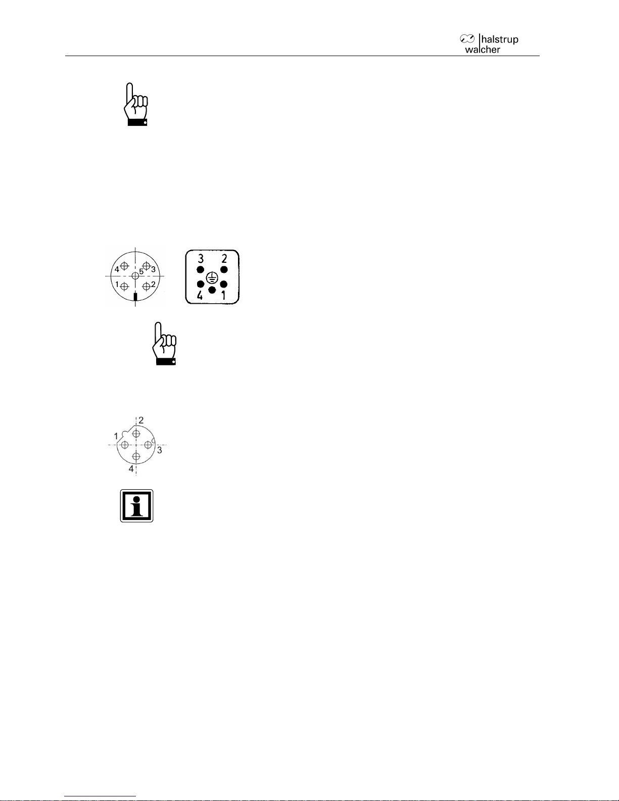
2.3 Pin assignment
For the supply voltage either a Binder series 713/763 (A-coded) round, 5-pin plug for PSE and
PSS devices or a 5-pin Harting plug with protective sleeve (HAN4A) for the PSE34xx devices
is located in the housing cover of the PSx3xxSE.
Two round 4-pin sockets, Binder series 825 (D-coded) are provided for connection to the bus.
2.3.1 Supply voltage connector
1. +24V motor
2. ground (motor)
3. +24V control unit
4. ground (control unit)
5. housing/pressure balance
To prevent the ingression of fluids into the PSW-housing during
cooldown, use a special cable with an airtube for pressure
balancing of your PSW.
2.3.2 Sockets for the bus
1. TD+ (WH/GN, white/green)
2. RD+ (WH/OG, white/orange)
3. TD- (GN, green)
4. RD- (OG, orange)
Due to the use of 4-pin sockets, only four-wire cables should be used.
2.3.3 Electrical grounding
Next to the connecting plugs there is a M4 stud bolt. It is recommended to connect the
positioning system with a cable as short as possible to the machine base. The minimum wire
cross section therefor is 1.5mm².
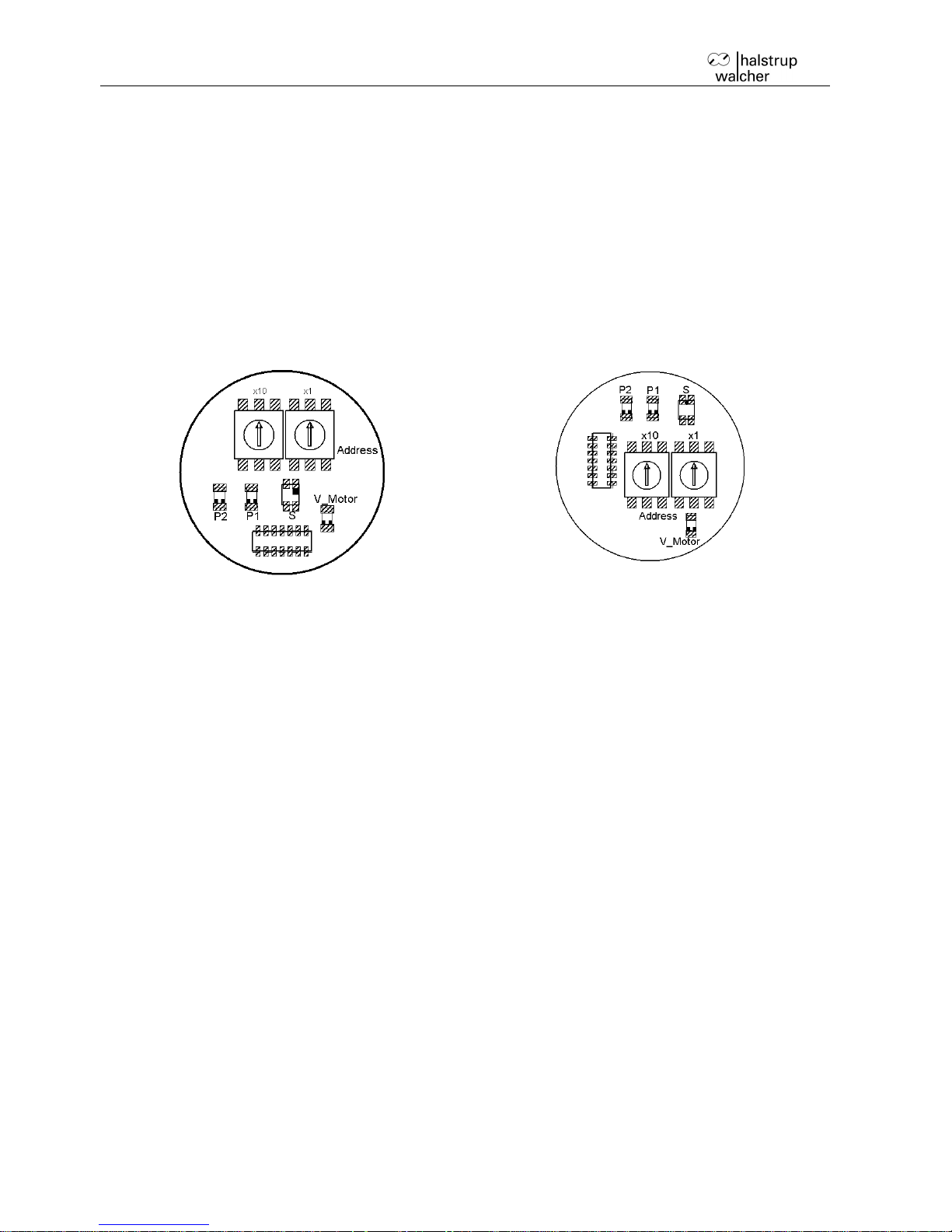
2.4 Setting the device address
In its delivery state, the PSx3xxSE has the address 1. A different address can be assigned
using the parameter S-0-1040 or via the optional address switches. If the switches are resting
in the position 00 or not available, the address is set using S-0-1040. The change in address is
saved automatically and therefore continues to be available after the device is restarted.
If you set the address using the switches (i.e. switches set to > 00) you cannot change this
value using the bus.
Page 7
Instruction Manual PSx3xxSE
7
2.5 LEDs and address switches
The following LEDs are located under the transparent sealing plug:
P1/P2: Green link LEDs for ports 1 and 2
S: sercos LED (see sercosIII specifications)
V-Motor: The LED is illuminated yellow when power is available to the motor.
OFF Motor power supply is too high or low
ON Motor power supply ok
flashing Motor power supply ok, PSx in delivery state
Address switch:
The rotary switches indicate the tens and ones places of the address selected. If the switches
are resting in the position 00 or are not available, the address is set using S-0-1040.
The delivery setting is 00, the PSE reports to the bus with the address 1.
If you set the address using the switches (i.e. switches set to > 00) you cannot change this
value using the bus.
2.6 sercosIII cycle data
The IO-profile is used with a fixed configuration (SCP_FixCFG). When configuring the
connections, you must be aware of the following:
S-0-1050.0.x are the settings for the AT (producer)
S-0-1050.1.x are the settings for the MDT (consumer)
The command and/or status bytes 'Connection Control', 'Positioning Control' and 'Producer
RTB word container' are initialised with 0 during the change from CP3 to CP4.
2.6.1 Master to PSx3xxSE (MDT)
Bit
Byte
Meaning
Corresponding IDN
0-15
0-1
Connection control
S-0-1050.1.08
16-31
2-3
I/O Control
S-0-1500.00.01
32-47
4-5
Positioning control
S-0-0346
48-79
6-9
Positioning command value
S-0-0282
Page 8

Instruction Manual PSx3xxSE
8
Connection Control
Bit 15-12: Counter
Bit 1: New Data
Bit 0: Producer ready
A run command will only accepted if this bit is set.
I/O Control
Bit15: Output operation state
A run command will only accepted if this bit is set.
Positioning control (control word)
Bit 2-1: Positioning modes
00: Positioning Drive moves to the transferred target value
01: Jogging + Drive moves to the upper limit switch
10: Jogging - Drive moves to the lower limit switch
11: Positioning Halt Drive brakes with the specified deceleration ramp
(can also be used in jogging mode)
Bit 0: Toggle
Must be toggled if a run command is to be accepted.
2.6.2 PSx3xxSE to Master (AT)
Bit
Byte
Meaning
Corresponding IDN
0-15
0-1
Connection control
S-0-1050.0.08
16-31
2-3
I/O status
S-0-1500.00.02
32-47
4-5
Producer RTB word container
S-0-0144
48-63
6-7
Torque feedback value
S-0-0084
64-95
8-11
Velocity feedback value 1
S-0-0040
96-127
12-15
Position feedback value 1
S-0-0051
Connection Control
Bit 15-12: Counter
Bit 1: New data
Bit 0: Producer ready
I/O status
Bit 15: Outputs ready to operate
is set as soon as bit 15 is set in the I/O control
Bit 14: Inputs valid
always 1
Bit 13: Error of resource I/O (C1D)
Error code is in S-0-0390 and diagnosis text in S-0-0095
Bit 12: Warning of resource I/O (C2D)
Error code is in S-0-0390 and diagnosis text in S-0-0095
Producer RTB word container (status word)
Bit 3: Positioning halt
Drive was stopped (by 'positioning halt' command in the control word)
Bit 2: In position (S-0-0336, bit 0)
Drive is within the positioning window
Bit 1: Status command value processing (S-0-0135, bit 3)
Drive is running
Bit 0: Takeover positioning command value (S-0-0419, bit 0)
Accept target value (is toggled)
Page 9

Instruction Manual PSx3xxSE
9
2.7 Parameters
2.7.1 Read only parameters
Name,
designation
IDN
Function
Unit
Byte count/ data
type
Actual rpm
S-0-0040
Current rpm
rpm
4 /
signed decimal
Actual position
S-0-0051
Current position
*
4 /
signed decimal
Actual torque
S-0-0084
Current torque value
cNm
2 /
signed decimal
In position
S-0-0336
Drive is in the positioning
window
-
2 /
binary
Motor supply
voltage
S-0-0380
Current supply voltage for
the motor
V
2 /
unsigned decimal
Temperature
S-0-383
Internal temperature of the
device
°C
2 /
unsigned decimal
Error text
S-0-0095
Error in text form
-
Full text
Diagnosis code
S-0-0390
Code for errors and/or
warnings (see Section 0)
-
4 /
hexadecimal
Vendor code
S-0-1300.0.3
sercosIII Vendor code (10)
-
2 /
unsigned decimal
Device type
S-0-1300.0.5
PSE3xx-xx bzw.
PSE3xxVG-xx
-
Full text
Software version
S-0-1300.0.9
x.xx
-
Full text
Serial number
S-0-1300.0.12
Device serial number
-
Full text
Production date
S-0-1300.0.13
YYYY-MM-DDTHH:MM:SSZ
-
Full text
Maximum torque
P-0-0084
Maximum torque value
during the last run, not valid
in the acceleration and
deceleration phase
cNm
2 /
signed decimal
Control unit
voltage
P-0-0380
Current supply voltage for
control unit
V
2 /
unsigned decimal
* The units are dependent on the scale (S-0-0079 and P-0-0079).
Page 10

Instruction Manual PSx3xxSE
10
2.7.2 Writable parameters
Name,
designation
IDN
Function
Byte
/
Type
Upper limit
S-0-0049
Maximum permitted target position
Unit: *
Min.: lower limit
Max.: positioning range – 3 rotations
Default setting: 101200
Changes only possible when at a standstill
4 /
sd
Lower limit
S-0-0050
Minimum permissible target position
Unit: *
Min.: positioning range – 253 rotations
Max.: upper limit
Default setting: 1200
Changes only possible when at a standstill
4 /
sd
Referencing of
the position
S-0-0052
Writing causes the current position to be "referenced" onto
the transferred value The limit switch and the positioning
range are also shifted. The difference is found in S-0-0175.
Unit: *
Min./Max.: Any desired value
Default setting: 0
Changes only possible when at a standstill
4 /
sd
Direction of
rotation
S-0-0055
When looking at the output shaft:
16: clockwise
23: counter clockwise
Default setting: 16
Changes only possible when at a standstill
2 /
bin
Positioning
window
S-0-0057
Permissible difference between target and actual values for
the "in position" bit (S-0-0336)
Unit: *
Min.: 1*
Max.: 100*
Default setting: 2
Changes only possible when at a standstill
4 /
ud
Loop length
S-0-0058
Number of increments, which the drive runs to a target in a
specified direction.
Run without loop with value 0
Unit: *
Min.: -400*
Max.: 400*
Default setting: -250
Changes only possible when at a standstill
4 /
sd
Scale for
positional data
S-0-0079
Increments per revolution, e.g. spindle pitch 1.5 mm with
resolution 1/100 mm 150
Min.: 1
Max.: 10000
Default setting: 400
Changes only possible when at a standstill
4 /
ud
Maximum
torque
S-0-0092
Max. permissible torque during the run
Unit: cNm
Default setting: **
2 /
ud
Page 11

Instruction Manual PSx3xxSE
11
Name,
designation
IDN
Function
Byte
/
Type
Drag error
S-0-0159
Max. drag error before a C2D warning is generated
Monitoring deactivated with 0.
Unit: *
Min.: 0
Max.: 1000*
Default setting: 0
4 /
ud
Reference
value
S-0-0175
Correction factor for the target, actual and limit switch
values
Unit: *
Min./Max.: Any desired value
Default setting: 0
Changes only possible when at a standstill
4 /
sd
Target rpm
S-0-0259
Rpm to be used for positioning runs
Unit: rpm
Min./Max.: **
Default setting: **
4 /
sd
Acceleration
S-0-0260
Acceleration ramp
Unit: rotations/(min * sec)
Min./Max.: **
Default setting: **
4 /
sd
Positioning
range
S-0-0278
Definition of the positioning range relative to the absolute
value encoder
Unit: *
Min.: actual position + 3 rotations
Max.: actual position + 253 rotations
Default setting: 102400
Changes only possible when at a standstill
4 /
sd
Target value
S-0-0282
Specified target position (can be written using SVC in CP24 ), stop by writing the same target value once again
Unit: *
4 /
sd
Deceleration
S-0-0359
Deceleration ramp
Unit: rotations/(min * sec)
Min./Max.: **
Default setting: **
4 /
sd
Holding torque
S-0-0533
Holding torque at standstill
Unit: cNm
Min.: 0
Max.: **
Default setting: **
4 /
sd
Maximum startup torque
S-0-0822
Max. permissible torque in the start-up phase
Unit: cNm
Min./Max.: **
Default setting: **
2 /
ud
Time for startup torque
S-0-0823
Time in which the start-up torque applies
Unit: msec
Min.: 10
Max.: 1000
Default setting: 200
2 /
ud
Page 12

Instruction Manual PSx3xxSE
12
Name,
designation
IDN
Function
Byte
/
Type
Address
S-0-1040
sercosIII address
Min.: 1
Max.: 511
Default setting: 1
2 /
ud
Extended scale
for positional
data
P-0-0079
Used in combination with S-0-0079 to set "unlevel"
resolutions
Min.: 1
Max.: 10000
Default setting: 400
Changes only possible when at a standstill
4 /
ud
Drag error
correction factor
P-0-0159
Drag error correction is deactivated with the value 0.
Min.: 0
Max.: 10
Default setting: 0
Changes only possible when at a standstill
2 /
ud
Holding torque
at completion of
run
P-0-0822
Holding torque at completion of run
Unit: cNm
Min.: 0
Max.: **
Default setting: **
2 /
ud
Time for holding
torque at
completion of
run
P-0-0823
Time for holding torque at completion of run
Unit: cNm
Min.: 0
Max.: **
Default setting: **
2 /
ud
Adjustment
release
P-0-0900
Adjustment with value = 1 (only for PSE without brake)
Min.: 0
Max.: 1
Default setting: 0
2 /
ud
* * The units and/or values are dependent on the scale (S-0-0079 and P-0-0079).
** The value depends on the type of device (see following table).
Page 13

Instruction Manual PSx3xxSE
13
2.7.3 Table of type-dependent values
Device type
PSE and PSS
301-x
311-x
302-x
312-x
305-x
315-8
322-14
332-14
325-14
335-14
Name, designation
IDN
Range of values
Delivery state
Max. torque
S-0-0092
2..125
100
10..250
200
50..600
500
10..250
200
20..500
400
Target rpm
S-0-0259
15..230
230
10..150
150
3..70
70
20..200
170
10..100
85
Acceleration
S-0-0260
97..600
600
50..400
400
23..130
130
97..525
525
50..260
260
Delay
S-0-0359
97..600
600
50..400
400
23..130
130
97..525
525
50..260
260
Holding torque
S-0-0533
0..90
30
0..150
50
0..300
100
0..100
35
0..200
70
Start-up torque
S-0-0822
2..125
125
10..250
250
50..600
600
10..250
250
20..500
500
Holding torque at
completion of run
P-0-0822
0..180
60
0..300
100
0..600
200
0..200
70
0..400
140
Device type PSW
301-x
311-x
302-x
312-x
305-x
315-8
322-14
332-14
325-14
335-14
Name, designation
IDN
Range of values
Delivery state
Max. torque
S-0-0092
2..125
100
10..250
200
50..600
500
10..250
200
20..500
400
Target rpm
S-0-0259
15..180
180
10..125
125
3..60
60
20..150
125
10..80
60
Acceleration
S-0-0260
97..600
600
50..400
400
23..130
130
97..525
525
50..260
260
Delay
S-0-0359
97..600
600
50..400
400
23..130
130
97..525
525
50..260
260
Holding torque
S-0-0533
0..90
30
0..150
50
0...300
100
0..100
35
0..200
70
Start-up torque
S-0-0822
2..125
125
10..250
250
50..600
600
10..250
250
20..500
500
Holding torque at
completion of run
P-0-0822
0..180
60
0..300
100
0..600
200
0..200
70
0..400
140
Page 14

Instruction Manual PSx3xxSE
14
Device type PSE
3110-14
3125-14
3410-14
3418-14
Name, designation
IDN
Range of values
Delivery state
Max. torque
S-0-0092
100..1200
1000
250..3000
2500
200..1200
1000
500..2000
1800
Target rpm
S-0-0259
1..30
30
1..12
12
10..100
100
10..90
90
Acceleration
S-0-0260
9..50
50
4..20
20
20..350
350
10..315
315
Delay
S-0-0359
9..50
50
4..20
20
20..350
350
10..315
315
Holding torque
S-0-0533
0..600
200
0..1250
450
0..300
200
0..450
300
Start-up torque
S-0-0822
100..1200
1200
250..3000
3000
200..1200
1200
500..2000
2000
Holding torque at
completion of run
P-0-0822
0..1200
400
0..2500
900
0..600
400
0..900
600
2.7.4 Commands
Name, designation
IDN
Function
Delete error
S-0-0099
Deletes the C1D error
Load default settings
S-0-0262
The default settings are loaded. In order to save these
permanently, you must subsequently execute S-00264
Save settings
S-0-0264
Saves the parameter in EEPROM
2.8 Error messages
Errors (C1D) and warnings (C2D) are reported using bits 13 and 12 in the I/O status. The
diagnosis code is stored in S-0-0390 and the diagnosis text in S-0-0095.
2.8.1 Error (C1D)
The sercos LED is illuminated red when an error occurs.
When an error occurs during the run, the run is aborted. No further run commands will be
accepted until the error is deleted. Errors are deleted using IDN S-0-0099. If the error
continues, the error message will be displayed again.
The type of error can be found in the diagnosis code (S-0-0390).
0xC00F2019: Internal device temperature exceeds specified limit.
0xC00F2026: Motor voltage too low (voltage < 17.5V).
0xC00F2055: Obstruction (extreme difficulty running, insufficient torque).
0xC00F8022: Error in calculating/determining the absolute position.
This error cannot be deleted. If necessary, restart drive.
0xC00F8025: Motor voltage too high (voltage > 30V).
0xC00F8028: Motor current too high.
0xC10F6320: Incorrect parameters (error in loading or saving).
This error cannot be deleted. Restart the drive and, if the error continues, load the default
settings with S-0-0262.
Page 15

Instruction Manual PSx3xxSE
15
2.8.2 Warnings (C2D)
A warning does not result in a run being aborted. Run commands continue to be accepted
when warnings are active. The drive issues the following warnings (S-0-0390):
0xC00E2028: Drag error (see Section 3.4)
A new run command deletes this warning.
0xC00E2053: Invalid target value, target value lies outside the permissible positioning range.
A new run command deletes this warning.
0xC00E6043: Upper limit exceeded.
Warning is deleted as soon as the drive is within the permissible positioning range.
0xC00E6044: Lower limit exceeded.
Warning is deleted as soon as the drive is within the permissible positioning range.
3 Special features
3.1 Positioning
To perform a positioning run, the control word (positioning control) must be written as follows
in the MDT: bit 2-1 = 00 and bit 0 must be toggled. When the run command has been
successfully accepted, the bit 0 in the status word (Producer RTB word container) is toggled in
the AT.
Here are the responses in various situations:
New target value during a run
The new target position is accepted immediately. If a change of direction is required, the drive
brakes using the set deceleration ramp and then approaches the new target value.
Stop command
To perform a stop command, the control word (positioning control) is written as follows in the
MDT: bit 2-1 = 11 and bit 0 must be toggled.
Stop command during a run:
The drive brakes using the maximum possible deceleration ramp.
There will be no readjustment of the position (see also readjustment P-0-0900).
Bit 3 (positioning halt) in the status word (Producer RTB word container) will be set.
Stop command during standstill:
Bit 2 (in position) in the status word (Producer RTB word container) will be set to 0.
There will be no readjustment of the position (see also readjustment P-0-0900).
Toggling bit 0 of the control word (positioning control) in the MDT leads to
the generation of a run command in the drive even if the drive is already at
the target value because the internal resolution is higher. Constant toggling
of bit 0 must therefore be avoided.
Runs, which involve a run to an obstruction (e.g. reference runs to a block),
may only be started with reduced torque (max. run torque < 10% of
nominal torque).
Underwater usage of the PSW is not allowed.
Page 16

Instruction Manual PSx3xxSE
16
3.1.1 Positioning sequence with loop
The loop length (S-0-0058) has the effect of ensuring that a target value is always approached
from the same direction. This allows you, for example, to eliminate the lash in a driven spindle.
The diagram below illustrates the function of the loop length:
If the target value is above the current position (actual value 1) and the loop length is > 0, the
drive runs past the target value by the specified loop length (run 1a) and then runs to the
target value (run 1b).
If the target value is below the current position and the actual value (actual value 2) is outside
the loop length, the drive approaches the target value directly (run 2).
If you wish to approach the position from the left, the loop length must be < 0.
It is not possible to perform a positioning run to the upper limit (S-0-0049)
with a loop length > 0 because the drive would have to run past the upper
limit in order to do so. The same applies to the lower limit (S-0-0050) with a
loop length < 0.
3.1.2 Positioning sequence without loop
Positioning runs from both directions are possible without a loop if the loop length (S-0-0058)
is set to 0. This does NOT eliminate any lash present in the spindle. The PSx3xxSE internal
gear backlash does not play a role in this case, as position data are acquired directly at the
output shaft.
3.2 Speed, acceleration and delay
The target speed from S-0-0259, acceleration from S-0-0260 and delay from S-0-0359 apply
for all runs. As the drive approaches the target at the end of the run, the delay is successively
reduced in order to ensure a harmonious transient response.
If a stop command is executed, the drive brakes with the maximum possible deceleration
ramp.
3.3 Response if the drive encounters an obstacle or is turned manually
If during a run the achievable rate of speed falls below the threshold parameter (30% of the
target speed) for longer than 200 ms, the instrument registers an obstacle, aborts the run and
a C1D error message is generated (diagnosis code: 0xC00F2055). The drive then stands still
with the set holding torque (S-0-0533). A new run command will only be accepted when the
error has been deleted (see Section 0).
If, when the drive is at a standstill, it is pushed out of the positioning window, the bit 'In
Position' (see Section 2.6.2) will be deleted. If readjustment is active (S-0-0900), the drive will
return to the target value.
Page 17

Instruction Manual PSx3xxSE
17
3.4 Drag error
3.4.1 Monitoring
During a positioning run, the instrument compares the computed target position with the
current actual value. If the difference is greater than the value "drag error" (S-0-0159), a
warning (C2D) is generated (diagnosis code: 0xC00E2028). This applies in particular if the
target speed cannot be achieved due to external influences (required torque, motor voltage too
low). Monitoring of the drag error can be deactivated by setting S-0-0159 to 0.
3.4.2 Correction
The drag error correction can be activated with P-0-0159. The target rpm is increased or
reduced by the specified factor proportionally to the drag error. It is recommended that you set
the parameter to 4.
3.5 Readjustment
When P-0-0900 is set to the value 1, the drive performs a readjustment if it is pushed out of
the positioning window after a run has been completed. If the loop length (S-0-0058) is not
equal to 0, the drive will only readjust if it is pushed out of position in the direction of the loop. If
the loop length = 0, the drive will readjust in both directions.
If a stop command is sent, the drive will only readjust when a new run command is sent.
This function is only available for drives without brake.
3.6 Absolute measuring system
The PSx3xxSE actuator includes an absolute measuring system capable of covering a range
of 256 rotations. In order to prevent an overrun if the drive is rotated by an external force when
it is switched off, the drive can be positioned in a range of 250 rotations. The three lower and
upper rotations of the measurement range are therefore blocked.
Removal of the supply voltage to the motor has no effect on the internal
measurement system.
3.6.1 Positioning range (S-0-0278)
S-0-0278 is used to map the desired positioning range onto the physical range of the machine.
In the delivery state, the drive is at position 51200, the upper limit switch is set to 101200 and
the lower limit switch is set to 1200, yielding a positioning range of ±125 rotations (±50000
increments). If the desired positioning range does not exceed ±125 rotations, none of the
steps described below are required to set the range.
The following two options are available to allow you to realise any desired positioning run
distances independently of the run distance set by the mounting orientation of the
measurement system (physical positioning range):
1. Bring the axle to be moved (e.g. a spindle) into the desired position, run the drive to the
appropriate position with the adjustable collar open and then close the adjustable collar.
Examples:
Bring the axle to be positioned into the mid-position, run the drive to the mid-position (position
51200) with the adjustable collar open, then close the adjustable collar. The drive can now run
125 rotations in both directions (default ±50000 increments).
Page 18

Instruction Manual PSx3xxSE
18
Bring the axle to be positioned all the way to the left (or bottom), run the drive without a loop to
the smallest position (position 1200) and with the adjustable collar open, and then close the
adjustable collar. The drive can now run 250 rotations to the right (or top) (default ±100000
increments).
Bring the axle to be positioned all the way to the right (or top), run the drive to the largest
position (position 101200) with the adjustable collar open, then close the adjustable collar. The
drive can now run 250 rotations to the left (or bottom) (default ±100000 increments).
2. Mount the drive in the required position on the axle, close the adjustable collar, then
adjust the positioning range using S-0-0278. The parameter sets the upper end of the
positioning range. Default setting: upper end at +256 rotations (position 102400). If, after
mounting the drive, the positioning range does not match the currently displayed position, you
can select the positioning range between +3 …+253 rotations from the current position as
required.
Examples:
After mounting the drive, the position 51200 is displayed (this corresponds to the delivery
state). The positioning range should point exclusively to the right (or top) +253 rotations:
Positioning range = actual position + scale * number of rotations
S-0-0278 = S-0-0051 + (400 * S-0-0079 / P-0-0079) * number of rotations
152400 = 51200 + (400 * 400 / 400 ) * 253
After mounting the drive, position 100000 is displayed. However, the positioning range should
point exclusively to the right (or top) +253 rotations:
Positioning range = actual position + scale * number of rotations
S-0-0278 = S-0-0051 + (400 * S-0-0079 / P-0-0079) * number of rotations
201200 = 100000 + (400 * 400 / 400 ) * 253
After mounting the drive, position 2000 is displayed. However, the positioning range should
point exclusively to the left (or bottom) +3 rotations:
Positioning range = actual position + scale * number of rotations
S-0-0278 = S-0-0051 + (400 * S-0-0079 / P-0-0079) * number of rotations
3200 = 2000 + (400 * 400 / 400 ) * 3
The numbers of increments or position values indicated relate to the following settings, which
correspond to the delivery state:
Referencing value (S-0-0175) = 0
Scale for the positional data (S-0-0079 and P-0-0079) = 400
When the positioning range (S-0-0278) is changed, the upper limit is set to the value
(positioning range – 3 rotations * scale) and the lower limit to the value (positioning range –
253 rotations * scale). This gives a total positioning range of 250 rotations.
3.6.2 Scale for the positional data (S-0-0079 and P-0-0079)
These parameters influence the number of increments generated per rotation.
The scale can be calculated using the following formula:
00790
00790*400
P
S
rotation
increments
The most advisable approach is to leave P-0-0079 at 400 and then set the increments/rotation
using S-0-0079.
Examples:
Page 19

Instruction Manual PSx3xxSE
19
The positional data should be scaled in degrees relating to the output shaft:
1 rotation = 360° S-0-0079 = 360; P-0-0079 = 400
The drive is to be operated on a 4mm spindle with a resolution of 1/100 mm:
1 rotation = 4 mm= 400 increments S-0-0079 = 400; P-0-0079 = 400
The drive is to be operated on a 4mm spindle with a resolution of 1/10 mm:
1 rotation = 4 mm= 40 increments S-0-0079 = 400; P-0-0079 = 40
The drive is to be operated on a 2mm spindle with a resolution of 1/100 mm:
1 rotation = 2 mm= 200 increments S-0-0079 = 200; P-0-0079 = 200
The drive is to count 138.23 increments per rotation:
1 rotation = 138.23 increments S-0-0079 = 320; P-0-0079 = 926
When you change the scale for the positional data, the actual value, the referencing value, the
positioning range, the upper and lower limits, the positioning window and the loop length are
recalculated.
3.6.3 Direction of rotation (S-0-0055)
The direction of rotation allows you to specify in which direction the drive should rotate during
runs to larger target values.
When looking at the output shaft, the following values are possible:
16: clockwise
23: counter clockwise
When you change the direction of rotation (S-0-0055), the referencing value (S-0-0175), the
positioning range (S-0-0278) and the upper and lower limits (S-0-0049 and S-0-0050) are set
to the delivery state.
3.6.4 Referencing (S-0-0175) and/or (S-0-0052)
Using the referencing value (S-0-0175) you can shift the whole range of values. There are two
ways of setting the referencing value:
Directly – by writing the referencing value in S-0-0175.
Indirectly – by writing a position value in S-0-0052. This allows any actual value to be assigned
to the current actual value. The resulting difference is then the referencing value (in S-0-0175).
A change to the referencing value automatically shifts the actual value, positioning range and
the upper and lower limits by the same value.
3.6.5 Setting parameters without automatic adjustment
If the user wants to avoid any automatic adjustment of values when setting the parameters for
the drive, the optimum order for sending the parameters is as follows:
Direction of rotation (S-0-0055)
Scale for the positional data (S-0-0079)
Extended scale for the positional data (P-0-0079)
Referencing value (S-0-0175) and/or referencing of the position (S-0-0052)
Positioning range (S-0-0278)
Upper limit (S-0-0049)
Lower limit (S-0-0050)
Positioning window (S-0-0057)
Loop length (S-0-0058)
In order to save the settings permanently in the EEPROM, you must then use S-0-0264 (see
Section 2.7.4).
Page 20

Instruction Manual PSx3xxSE
20
4 Technical data
4.1 Ambient conditions
ambient temperature
0 °C to +45 °C
storage temperature
-10 °C to +70 °C
shock resistance according to
DIN IEC 68-2-27
50 g 11 msec
resistance to vibration
according to DIN IEC 68-2-6
10 Hz to 55 Hz 1.5 mm
55 Hz to 1000 Hz 10 g
10 Hz to 2000 Hz 5 g
EMC standards
CE
conformity
CE declaration of conformity available upon request
protection class
PSE
IP 54
PSS
IP 65
PSW
IP 66 (in operation)
IP 68 (at standstill)
duty cycle
Device model
Duty cycle in
%
Base time in sec.
PSE34xx
PSE30xx to 33xx
PSS
PSW
20
30
20
20
300
300
600
600
4.2 Electrical data
Nominal power output
PSx30xSE, PSx31xSE,
PSE31xxSE
25 W with 30 % OT
PSx32xSE, PSx33xSE
35 W with 30 % OT
PSE34xxSE
100 W with 20 % OT
Supply voltage
24 VDC ±10 % (supply voltages for motor and control
unit are galvanically separated)
Recommendation: Use a regulated power adapter
Nominal current, control unit
0.15 A
Nominal current, motor
PSx30xSE, PSx31xSE,
PSE31xxSE
2.2 A
PSx32xSE, PSx33xSE
3.0 A
PSE34xxSE
7.8 A
Positioning resolution
0,9°
Positioning accuracy
0.9°
Absolute value acquisition
Optical - magnetic
Page 21

Instruction Manual PSx3xxSE
21
4.3 Physical data
Positioning range
250 usable rotations, no mechanical limits
measuring system has a span of 256 turns, minus 3
turns security stock at upper and lower range limit
torsional rigidity
(angle of rotation when
switching from operation
without backlash to maximum
torque)
max. 0.2°
gear backlash
(without spindle
compensation run)
max. 0.5°
Spindle lash compensation
Automatic reference loop after every positioning run
(may be activated or deactivated)
Output shaft
PSE30xSE-8,
PSE31xSE-8
8H9 hollow shaft with
adjustable collar
PSE30xSE-14,
PSE31xSE-14,
PSE32xSE, PSE33xSE
14H7 hollow shaft with
adjustable collar
PSE31xxSE,
PSE34xxSE
14H7 hollow shaft with
clamp and feather key
PSS3xxSE-8
PSW3xxSE-8
8H9 hollow shaft with
adj. collar or
8h8 solid shaft
PSS3xxSE-14
PSW3xxSE-14
14H7 hollow shaft with
adj. collar or
14h8 solid shaft
recommended diameter of
the spindle head
according to the hollow shaft diameter with an
interference fit of h9
Maximum radial force
40 N
Maximum axial force
20 N
Dimensions (l x w x h)
see catalog data on our website
Weight (approx.)
PSx30xSE-8
650 g
PSx30xSE-14, PSx32xSE
1200 g
PSx31xSE-8
700 g
PSx31xSE-14, PSx33xSE
700 g
PSE31xxSE
1200 g
PSE34xxSE
1900 g
For additional specifications and dimension drawings, please visit our website at
http://www.halstrup-walcher.de/en/produkte/positioniertechnik/positioniersysteme/index.php
7100.005054G_PSx3xxSE.doc 03/2017Ed
Page 22

Instruction Manual PSx3xxSE
22
 Loading...