

Page 1
Assembly instructions
halstrup-walcher GmbH
Stegener Straße 10
79199 Kirchzarten, GERMANY
Tel. +49 (7661) 39 63-0
info@halstrup-walcher.de
www.halstrup-walcher.de
© 18.03.2019, Kö
7100.006194 PS17 Assembly instructions
1 2 3
4
5
6a
6b
PS17 Differential pressure transmitter
PS 17 Differential pressure transmitter
The PS17 is a stationary differential pressure transmitter used
for recording positive and negative differential pressures and
converting them into electrical signals.
The device is designed for use in cleanrooms, machines, filter
technology and heating, ventilation and air-conditioning systems
(HVAC). It is used to measure the differential pressure of nonaggressive and non-combustible gases up to 10 kPa.
The device may only be used in the allowed measuring range
(see type label).
Symmetrical and asymmetrical measurement ranges can be
measured with the piezoresistive pressure transmitter.
Models
The device is available in different models:
- With one fixed measurement range or
toggling between 4 different measurement ranges
- 3 supply connection options:
a. 24 VAC / DC (with reverse polarity protection)
b. 15.. 32 VDC (2-wire)
c. 24 VDC (with galvanic separation)
- 3 electrical connection options:
a. 2 cable glands M16
b. 1 cable gland M20 (not for version with relay)
c. 1 connector M12 (not for version with relay)
- Optional with 3 ½-digit display
- Optional with contact point/relay (not for 2-wire, cable gland
M20 or connector M12)
The time constant and output signal are default settings (see
type label). However, these settings can be configured.
Configure settings
The device has numerous possible settings:
- Adjustment of time constant
- Zero-point calibration of measured values
- Fine adjustment of final value
- Restore factory settings
- Configure output signal
- Adjust measuring range (optional)
- Set relay/switching threshold (optional)
To adjust these functions, please use the detailed operating
instructions at:
www.halstrup-walcher.de/technischedoku.
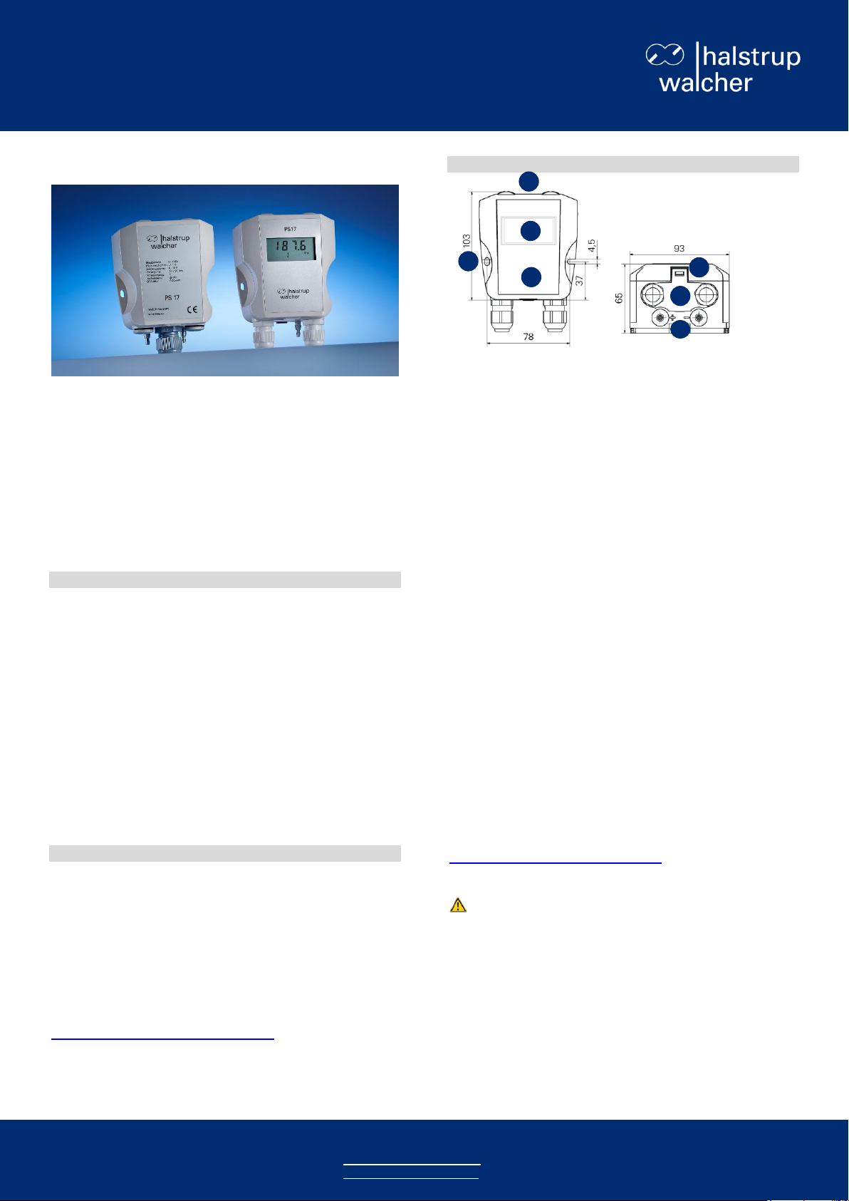
Control units and dimensions of the device
1. Display (optional)
2. Mounting option
- Wall mounting with 2 screws
- Top-hat rail mounting
3. Electrical connection option
- 2 cable glands M16
- 1 cable gland M20
- 1 connector M12
4. Hose connections 4 or 6 mm
5. Flap for opening the housing
6. Type label
a. Version without display
b. Version with display
Safety precautions
These assembly instructions are part of the product. Please read
the instructions carefully, follow our handling instructions and
pay particular attention to the safety precautions. The
instructions should be on hand at all times. Please contact the
manufacturer if you do not understand any parts of these
instructions.
The device has been designed and tested to ensure its safety.
However, it may still be dangerous if used inappropriately.
Always observe the operating requirements indicated on the
type label and in the data sheet – particularly the permissible
supply voltage.
Installation may only be carried out by qualified personnel. The
device requires no maintenance. The device may only be
cleaned from the outside with a damp cloth. The individual
responsible for the electrical connections must be notified
immediately if the device is damaged. In the event of
malfunctions, please consult the detailed operating instructions
at:
www.halstrup-walcher.de/technicaldocu.
Repairs should only be carried out by the manufacturer.
WARNING
Inside the device there may be electrical conductors with a
voltage of 230 V (relay option).
The device must be disconnected from the power supply
and secured before opening!
The device may only be opened and connected to an
electrical power source by qualified personnel.
Page 2
Assembly instructions for differential pressure transmitter PS17
ZWL
2-wire
15 .. 32 VDC
AC/DC
3-/4-wire
24 VAC/DC
VDC
4-wire with
galv. separation
24 VDC
1 2 3 4 5
1 2 3 4 5
1 2 3 4 5
1
+ connection
Inlet for
supply voltage
Inlet for
supply voltage
2
not assigned
Ground for
supply voltage or
output signal
Ground for
supply voltage
3
- connection
Output signal
(voltage/current)
Output signal
(voltage/current)
4
not assigned
Ground for
supply voltage or
output signal
Ground for
output signal
5
Zero-point
calibration input
+24V = active
Zero-point
calibration input
+24V = active
Zero-point
calibration input
+24V based on
ground for output
signal = active
Installing the device
You can mount the device on a top-hat rail or screw it to a wall.
Please observe the recommended mounting position.
Do not place the device too close to heat and
radiation sources.
1. Mounting on a top-hat rail/dismantling
The housing is prepared for mounting on a tophat rail.
1. Place the housing in the desired position with
the upper gap on the top-hat rail.
2. Lock the device in place by pushing it down.
The device is now mounted.
Note: To dismount the device,
use a screwdriver to pull the red
lug down.
2. Wall mounting
The device can be wall-mounted using 2 screws.
1. Prepare the drill holes.
2. Place the device on the wall.
3. Screw the right-hand screw into the wall
first, but don't make it too tight yet.
4. Screw in the left-hand screw.
5. Use the slots for alignment/adjustment.
6. Then tighten all the screws.
The device is now installed on a wall.
1. Loosen the flap with a screwdriver.
2. Fold the cover upwards until it locks in
place and remains open by itself.
The device is now open.
Note: To close the device, carefully push the cover towards the
closing flap of the housing until it locks in place. Make sure that
the device is properly closed to provide IP protection.
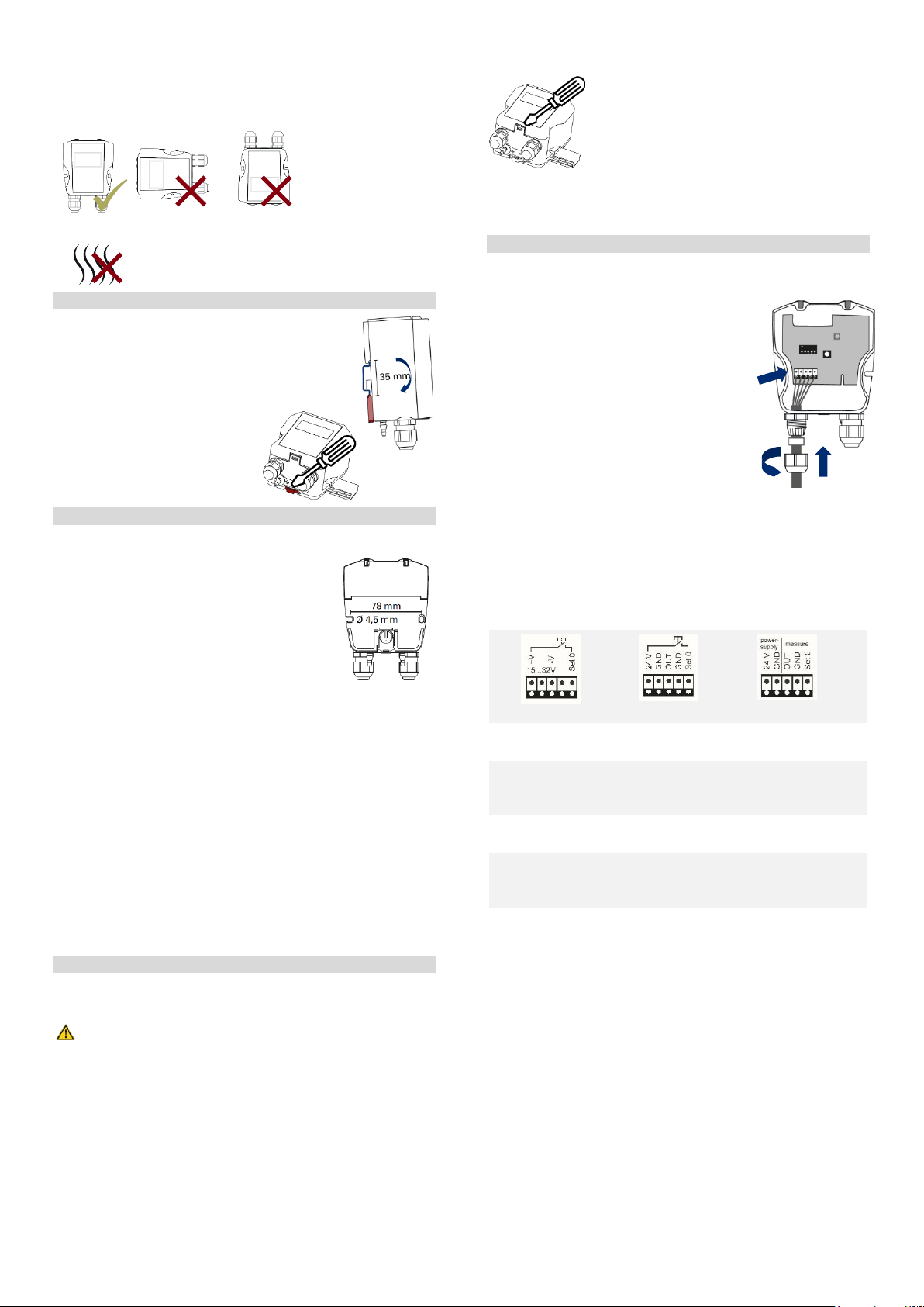
2. Connect supply voltage and output signal
You can connect the supply voltage, output signal and zero-point
calibration input. For devices with cable glands, the cables are
guided through the housing to the terminals.
1. Open the cable glands and thread the
cable in.
2. Guide the cable ends into the housing.
3. The terminals are located at the bottom
left of the circuit board.
4. Connect the cable ends according to
your version (see also connection
diagram in housing cover).
5. Ask your planner whether the digital
zero-point calibration input (Set 0) is
used.
6. Check the connection and close the
cable gland.
Connection diagram of supply options:
Connecting the hoses
You can connect hoses with a 4 or 6 mm inner diameter. Your
planner will instruct you about where to connect what hose.
Connecting to an electrical power
source
To connect the device to an electrical power source, you must
determine which connection version you have. In versions with
cable glands, you must open the housing to connect the device
to the electrical power.
Special versions with M12 supply plugs can be connected with
the prepared mating plugs on site. In this case, your planner will
provide the details.
1. Opening/closing the device
Carefully open the cover of the device to connect it to an
electrical power source.
WARNING
Inside the device there may be electrical conductors with a
voltage of 230 V (relay option).
The device must be disconnected from the power supply
and secured before opening!
The device may only be opened and connected to an
electrical power source by qualified personnel.
© 18.03.2019, Kö - 2 - 7100.006194 PS17 Assembly instructions
The device is now connected.
Outlook: After switching on, the device requires a warm-up
time of approx. 15 minutes until the temperatures of the
electronics and sensor have levelled off. The output signal may
behave unstable during this time.
Page 3

Assembly instructions for differential pressure transmitter PS17
3. Connect relay (optional)
You can connect the optional relay.
WARNING
Inside the device there may be electrical conductors with a
voltage of 230 V (relay option).
The device must be disconnected from the power supply
and secured before opening!
The device may only be opened and connected to an
electrical power source by qualified personnel.
1. The device must be switched off (free
of voltage) and opened
(see 1. Opening/closing the device).
2. Carefully slide the protective cover for
the relay contact to the left. To do this,
use the surface marked with an arrow
(above the pointer).
3. Now you have access
to the relay terminal.
4. Connect the relay’s supply voltage in
accordance with the connection diagram also
located on the circuit board above the
terminal:
5. Use the same procedure as in 2. Connect supply voltage.
6. Carefully slide the cover to the right again until it locks in
place. In doing so, please ensure that all relay connection
cables are under the cover.
The relay is now connected.
Close the device again.
© 18.03.2019, Kö - 3 - 7100.006194 PS17 Assembly instructions
 Loading...