

Page 1
Instruction Manual
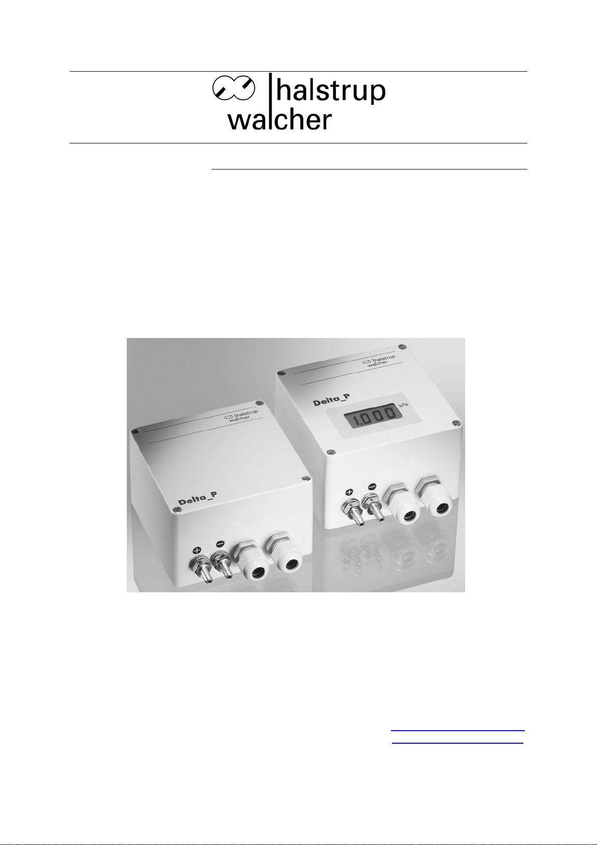
P82R Differential Pressure
Transducer with RootExtracted Characteristic
Curve
Document 7100.003244 Version 1.0 09/2005
halstrup-walcher GmbH
Stegener Straße 10
D-79199 Kirchzarten
Germany
Phone: +49 (0) 76 61/39 63–0
Fax: +49 (0) 76 61/39 63–99
E-Mail: info@halstrup-walcher.com
Internet: www.halstrup-walcher.com
Page 2

P82R Instruction Manual
Table of Contents
1 Safety precautions.............................................................................................................4
1.1 Appropriate use................................................................................................................4
1.2 Shipping, assembly, electrical connections and start-up.................................................4
1.3 Troubleshooting, maintenance, repairs, disposal ............................................................4
1.4 Symbols...........................................................................................................................5
2 Instrument description....................................................................................................... 6
3 Start-up...............................................................................................................................6
3.1 Features.........................................................................................................................6
3.2 Instrument connections..................................................................................................7
3.3 Output signals................................................................................................................8
4 Calibrating the zero point.................................................................................................... 9
5 Setting creep suppression.................................................................................................. 9
6 Troubleshooting................................................................................................................10
7 Technical data..................................................................................................................11
8 Dimension drawings ......................................................................................................... 13
2
Page 3

P82R Instruction Manual
Purpose of instruction manual
This instruction manual describes the features of the P82R differential pressure
transducer and provides guidelines for its use.
Improper use of this instrument or failure to follow these instructions may cause injury
or equipment damage. Every person who uses the device must therefore read the
manual and understand the possible risks. The instruction manual, and in particular
the safety precautions contained therein, must be followed carefully. Contact the
manufacturer if you do not understand any part of this instruction manual.
Handle this manual with care:
• It must be readily available throughout the lifecycle of the instrument.
• It must be provided to any individuals who assume responsibility for operating the
instrument at a later date.
• It must include any supplementary materials provided by the manufacturer.
The manufacturer reserves the right to continue developing this instrument model
without documenting such development in each individual case. The manufacturer
will be happy to determine whether this manual is up-to-date.
Conformity
This instrument corresponds to the state of the art and meets all legal requirements
set forth in EC directives as evidenced by the CE label.
© 2005
The manufacturer owns the copyright to this instruction manual. This manual contains
data, instructions and drawings pertaining to the features and usage of this
instrument; copying this manual in part or in full or distributing it to third parties is
prohibited.
3
Page 4

P82R Instruction Manual
1 Safety precautions
1.1 Appropriate use
In addition to differential pressure data, the P82R differential pressure transducer also
records positive and negative overpressures.
Always observe the operating requirements—particularly the permissible supply
voltage—indicated on the rating plate and in the "Technical data" section of this
manual.
The instrument may only be handled as indicated in this manual. Modifications to the
instrument are prohibited. The manufacturer is not liable for damages caused by
improper use or failure to follow these instructions. Violations of this type render all
warranty claims null and void.
1.2 Shipping, assembly, electrical connections and start-up
Do not close the pressure input ports when shipping, as changes in barometric
pressure could damage instruments with low measuring ranges.
Only technical personnel who are appropriately trained and authorized by the
operator of the facility may assemble the instrument and set up its electrical
connections.
The instrument may only be operated by appropriately trained individuals who have
been authorized by the operator of the facility.
Pressurized air or breath is not to be used for performance tests, as this could
damage instruments with low measurement ranges.
Measurement errors may occur if the instrument is not kept protected from sunlight.
Specific safety precautions are given in individual sections of this manual.
1.3 Troubleshooting, maintenance, repairs, disposal
The individual responsible for the electrical connections must be notified immediately
if the instrument is damaged or if errors occur that cannot be corrected as indicated in
section 6.
This individual must take the instrument out of service until the error has been
corrected and ensure that it cannot be used unintentionally.
Always unplug the power cord before opening the instrument!
This instrument requires no maintenance.
Only the manufacturer may perform repairs that require the housing to be opened.
4
Page 5

P82R Instruction Manual
The electronic components of the instrument contain environmentally hazardous
materials and materials that can be reused. For this reason the instrument must be
recycled in accordance with the environmental guidelines of the jurisdiction in
question once it has been taken permanently out of service.
1.4 Symbols
The symbols given below are used throughout this manual to indicate instances when
improper operation could result in the following hazards:
WARNING! This warns you of a potential hazard that could lead to bodily injury up
to and including death if the corresponding instructions are not followed.
WARNING: This warns you of a potential hazard that could lead to significant
property damage if corresponding instructions are not followed.
INFORMATION: This indicates that the corresponding information is important
for operating the instrument properly.
5
Page 6

P82R Instruction Manual
2 Instrument description
Its root-extracted characteristic curve makes this differential pressure transducer
especially suitable for measuring volume flow in equipment such as air-conditioning
units, fans and ventilation ducts. An optional display allows the operator to read out the
volume flow / flow rate directly on site.
3 Start-up
3.1 Features
Although the P82R pressure transducer is highly robust, it is nevertheless a precision
instrument and should be handled with care. Avoid mounting the instrument in the
direct vicinity of any sources of radiation or heat, such as heaters, as this could result
in measurement errors. Ideally, the instrument should be mounted vertically on a wall
not subject to vibration. Pressure (+) and vacuum (-) ports should be pointing down in
order to prevent any condensation from entering the measurement cell.
When connecting pressure to the transducer, use the following table to ensure that
the sign of the pressure (+ or -) is correct.
Type of pressure Connect pressure to Example
overpressure + input port 0...1 kPa
vacuum - input port 0...- 500 Pa
differential pressure higher pressure at + port
lower pressure at - port
0…125 Pa, e.g. via a differential
pressure transducer (e.g., a
measuring orifice)
6
Page 7

P82R Instruction Manual
3.2 Instrument connections
Fig. 1 (not all components are shown)
Terminal
11
13
11
13
Supply voltage
24/115/230 VAC 50/60 Hz
24/115/230 VAC 50/60 Hz
ground (GND)
+20.5 V...28.5 VDC
Terminal
1
2
3
4
Analog output
0...10 V
ground (GND)
0...20 mA / 4...20 mA
ground (GND)
7
Page 8

P82R Instruction Manual
Observe the required supply voltage (see rating plate) and the connection
diagram located on the housing cover.
The transducer outputs are protected from short circuits. Instruments supplied with
direct current are also protected from reverse polarity.
Connecting the supply voltage to the outputs will destroy the transducer.
3.3 Output signals
voltage output 0...10 V
UVU •= 10
linrad
U
10 V
U
rad
U
lin
0 V 100% p
current output 0...20 mA current output 4...20 mA
ImAI •= 20 mAmAImAI
linrad
I I
20 mA 20 mA
I
rad
0 mA 100 % p 4mA 100 % p
The S1 sliding switch (see fig. 1) allows the operator to toggle between a root-
extracted and linear curve.
root-extracted
linear
S1 switch
I
lin
linrad
I
rad
I
lin
4416 +−•=
8
Page 9

P82R Instruction Manual
Please note:
The LCD will not display the correct value when repositioning the S1 switch
(from root-extracted to linear).
4 Calibrating the zero point
Please remember that it takes roughly 30 to 60 minutes for the pressure
transducer to warm up after it is switched on. The output signal may not
remain stable during this period.
Set the S1 switch to “linear” before calibrating the zero point.
Turn the P5 trimmer (SMU =creep suppression) to the left stop position.
After the pressure transducer has warmed up, the operator may use the P1 or P4
trimmer to calibrate the zero point when current output is available (see figure 1),
taking care that the transducer is not connected to a source of pressure. This may
require having to disconnect the tubing from the pressure ports.
After calibrating the zero point, slide the S1 switch back to “root-extracted ”.
5 Setting creep suppression
U/I
0...10% 100% p
The creep-suppression function suppresses the pressure transducer output, i.e.,
keeps it at “0”, despite any existing pressure. The P5 trimmer can be used to set
creep suppression to a value between 0 and 10% of the measurement range. Use of
the creep-suppression function is advisable for many applications, as the instrument
will otherwise fail to generate reproducible results of a measurement when the flow
rate / volume flow is very low.
Use of the creep-suppression function limits the low end of the transducer
measurement range by 0 … 10%, depending on the settings. The output
signal will be kept at “0” despite any pressure present.
9
Page 10

P82R Instruction Manual
6 Troubleshooting
Error Description Potential Cause Corrective Action
no output signal
output signal is
constant, despite
change in pressure
output signal incorrect
• supply voltage is not
connected
• incorrect supply voltage
• defective fuse
• defective input protection
diode
• defective output protection
diodes
• pressure ports reversed
• creep suppression set too high
• defective output protection
diode
• defective pressure
measurement cell
for current output:
• output loadtoo high
for voltage output:
• connect correct supply voltage
• connect the correct supply voltage
(see rating plate).
• replace the SI1 fuse (Wickmann
model TR5 200 mAT)
• replace D3 (model SM6T33A)
• replace D6 / D7 (model SM6T18A)
• connect pressure as outlined in
section 3. “Mounting”
• Turn the P5 trimmer to the left until
the output signal ≠ 0 V / 0/4 mA
• replace D6 / D7 (model SM6T18A)
• Send the instrument to the
manufacturer for repair
• observe maximum output load of
500 Ω
zero point cannot be
adjusted using P1 / P4
Never use your breath to conduct a performance test, as this could destroy
the measurement cell.
Simple transducer performance test:
Connect tubing to the input port for overpressure. Pinch the tubing between
your index finger and thumb and carefully squeeze any existing air toward the
transducer.
• load resistance too low
defective pressure measurement
cell
• min. load resistance = 5 kΩ
Send the instrument to the
manufacturer for repair
10
Page 11

P82R Instruction Manual
7 Technical data
Measurement data
measurement ranges 0…100 Pa to 0…20 kPa (others available upon request)
overload capacity 5 x the final value of the measurement range
hysteresis <0.1 % of the starting range
warm-up period approx. 30 min.
time required for adjustment approx. 20 ms (up to 5 s available upon request)
deviation from characteristic curve
(starting point setting)
temperature-dependent drift in zero
point
temperature-dependent drift in
measurement range
dead volume
1 % of the starting range, root-extracted curve
0.04%/ K (within the +10°C...+50 °C range)
0.04%/ K (within the +10°C...+50 °C range)
approx. 2000 mm3 (for measurement ranges ≥ 250 Pa)
approx. 9000 mm
3
(for measurement ranges < 250 Pa)
control volume max. 200mm³
max. system pressure 100 kPa
Ambient conditions
medium air, all non-aggressive gases
nominal temperature +10° C to +50° C
operating temperature 0° C to +60° C
storage temperature -10° C to +70° C
relative humidity 0…80 %
EMC standards EN 50081 part 1 and EN 50082 part 1
conformity
Electrical data
declaration of conformity available upon request
power consumption max. 0.9 W
supply voltage 24 VDC +20% / -15%
(smoothed, permissible peak-to-valley ratio = 1000 mV)
230VAC, 115VAC, 24VAC +6 % / -15 %, 50/60 Hz
minimum load resistance R
maximum output load R
B
(optional)
L
RL ≥ 5 kΩ for voltage output
RB = 500 Ω for current output
display 3½ or 4½-place LCD, character height = 13 mm
(optional)
output signal 0 to 10 V, 0 to 20 mA or 4 to 20 mA; ±5 V and ±10 V are
also possible
Physical data
pressure port Ø 6.5 mm for NW5 tubing
(interior tubing diameter = 5 mm)
electrical connections screw terminals for cables up to 2.5 mm2
for power supply
screw terminals for cables up to 1.5 mm
for output signal
2
mounting orientation vertical
(when placing your order, please indicate if a horizontal
11
Page 12

P82R Instruction Manual
orientation is required)
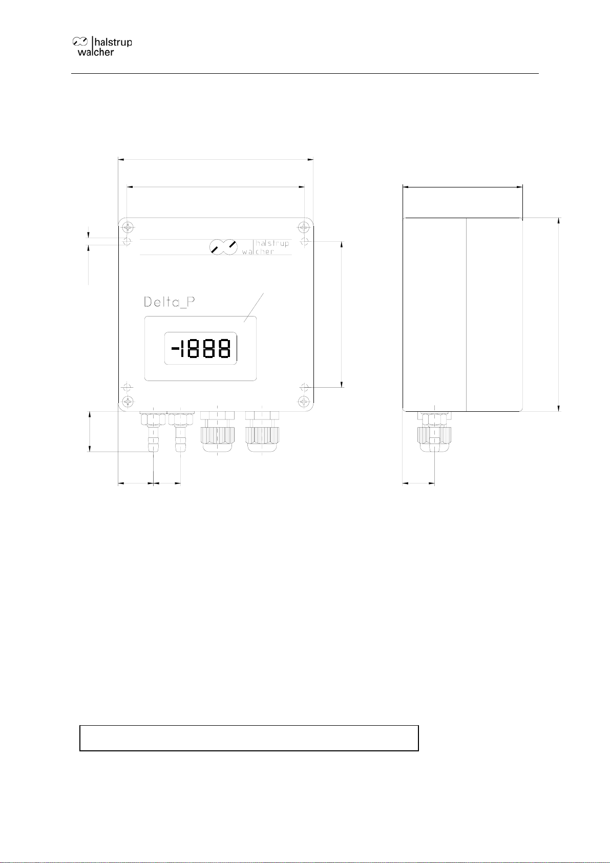
dimensions (w x h x d) 120 x 122 x 75 mm
protection class IP54
weight 0.8 kg
options
Appendix A: Parts in contact with measurement medium
• Beryllium bronze CuBe2 • Araldite CY236 / HY988
• Mu metal (nickel alloy) • Loctite 242e
• Brass CuZn39Pb3 • Carbonyl iron
• Aluminum AlCuMgPb / AlMg3 • KEL (FPM: fluorinated rubber)
• Silicon (tubing) optional: Viton • Vepuran Vu 4457/51
• Crastin (PTBP) • UHU-Plus endfest 300 binder
• 3½-place LCD
• 4½-place LCD
• linearity protocol
• DKD calibration certificate
• output signal attenuation up to 5 s
• silicon-free materials for parts in contact with medium
12
Page 13
P82R Instruction Manual
8 Dimension drawings
122
75
120
Ø4.5
111
Option LCD
90.5
+ -
25
17
22
20
7100.0003244_P82R_eng.doc 12.09.2005 ka/Ze
13
 Loading...